Article

Mechanical Properties Quantification of Steel Fiber-Reinforced Geopolymer Concrete with Slag and Fly Ash

1
Department of Civil Engineering, American University of Sharjah, Sharjah P.O. Box 26666, United Arab Emirates
2
Energy, Water, and Sustainable Environment Research Center, American University of Sharjah, Sharjah P.O. Box 26666, United Arab Emirates
*
Author to whom correspondence should be addressed.
Buildings 2025, 15(19), 3533; https://doi.org/10.3390/buildings15193533
Submission received: 16 August 2025 / Revised: 19 September 2025 / Accepted: 24 September 2025 / Published: 1 October 2025
(This article belongs to the Section Building Materials, and Repair & Renovation)

Abstract

This study examines the influence of steel fiber reinforcement on the mechanical properties of geopolymer concrete incorporating different slag to fly ash binder ratios (75:25, 50:50, and 25:75). Three fiber contents (0%, 1%, and 2%) by volume were used to assess their impact on compressive strength, flexural strength, initial stiffness, and toughness. Compressive tests were conducted at 1, 7, and 28 days, while flexural behavior was evaluated through a four-point bending test at 28 days. The results showed that geopolymer concrete with 75% slag and 25% fly ash experienced the highest compressive strength and modulus of elasticity, regardless of the steel fiber content. The addition of 1% and 2% steel fiber content enhanced the compressive strength by 17.49% and 28.8%, respectively, compared to the control sample. The binder composition of geopolymer concrete plays a crucial role in determining its compressive strength. Reducing the slag content from 75% to 50% and then to 25% resulted in a 15.1% and 33% decrease in compressive strength, respectively. The load–displacement curves of the 2% fiber-reinforced beams display strain-hardening behavior. On the other hand, after the initial crack, a constant increase in load causes the specimen to experience progressive strain until it reaches its maximum load capacity. When the peak load is attained, the curve gradually drops due to a loss in load-carrying capacity known as post-peak softening. This behavior is attributed to steel’s ductility and is evident in specimens 75S25FA2 and 50S50FA2. Concrete with 75% slag and 25% fly ash demonstrated the highest peak load but the lowest ultimate displacement, indicating high strength but brittle behavior. In contrast, concrete with 75% fly ash and 25% slag showed the lowest peak load but the highest displacement. Across all binder ratios, the addition of steel fibers enhanced the flexural strength, initial stiffness, and toughness. This is attributed to the bridging action of steel fibers in concrete. Additionally, steel fiber-reinforced beams exhibited a ductile failure mode, characterized by multiple fine cracks throughout the midspan, whereas the control beams displayed a single vertical crack in the midspan, indicating a brittle failure mode.

1. Introduction

Globally, conventional concrete is one of the most common construction materials due to its affordability and versatility. Conventional concrete also has remarkable mechanical properties, exceptional durability, and maintains its structural integrity after curing [1,2,3]. An average of 11 billion tons of concrete is produced annually [4]. The production of cement, which is a primary constituent material of concrete, is not only depleting the earth’s natural resources but is also contributing to global pollution. More than 1.5 million tons of raw materials and around 1300 kilowatt hours of embodied energy are required to produce a single ton of cement [5,6,7,8]. Moreover, the production of a single ton of Ordinary Portland Cement (OPC) is responsible for emitting nearly an equivalent amount of carbon dioxide (CO2) into the atmosphere. In fact, CO2 released during the production of OPC accounts for 5–7% of the global CO2 emissions [9]. In 2023, global carbon emissions totaled 36.8 billion tons, with cement production contributing approximately 7–8% of this amount [10]. Therefore, it is crucial to adopt alternative sustainable construction materials and binding agents that minimize or eliminate the need for cement [4].
A promising alternative is geopolymer concrete, which omits the use of conventional cement as a binding agent by using industrial by-products as substitutes. Industrial by-products include fly ash (FA), ground granulated blast-furnace slag (GGBS), steel slag, rice husk ash (RHA), metakaolin (MK), and palm oil fuel ash (POFA) [11,12,13]. This results in an eco-friendly material with a low carbon footprint and minimal water usage during geopolymerization [1].
Geopolymer is a composite material formed by the chemical reaction of various solid industrial by-products, such as slag and fly ash, which act as cement-like components, with alkaline activators [14,15,16,17]. This chemical process involves dissolving industrial by-products rich in aluminum and silicon in a strongly alkaline solution, causing the dispersed components to reorganize at the molecular level. As a result, the components precipitate and solidify, forming a durable structure [18]. The adoption of geopolymer concrete has the potential to significantly diminish greenhouse gas emissions by approximately 73% global energy consumption by around 43% [19]. The substantial amount of aggregates forming conventional concrete has a stronger negative influence on the environment compared to the alkaline activators in the GPC. This is because manufacturing aggregates requires significant energy, mainly from the operation of heavy machinery. This energy source emits significant amounts of greenhouse gases, which in turn impact the environment and surrounding freshwater ecosystems. Moreover, the demolition of GPC generates roughly 8.4% less waste than conventional concrete. However, the presence of alkalis in GPC poses significant environmental problems, as they can contaminate soil and groundwater. Therefore, GPC waste should be carefully disposed of [20].
Fly ash is a typical industrial waste utilized in the production of geopolymer concrete. Approximately 363 million tons of fly ash are produced globally, with India being the largest producer, followed by China and the United States [21]. Incorporating fly ash into concrete mixes helps conserve landfill space, reduce both water and energy consumption, and minimize greenhouse gas emissions [22]. Notably, utilizing the total annual supply of fly ash for concrete production is estimated to be equivalent to eliminating approximately 25% of the carbon dioxide emissions produced by vehicles worldwide [23]. Moreover, fly ash-based geopolymers produce 34.6% less greenhouse emissions than OPC. Furthermore, due to its small particle size, fly ash can significantly improve the density and frost resistance of geopolymer concrete, while also reducing its permeability. The American Concrete Institute (ACI) Committee 116R defines fly ash as a “finely divided residue formed by the burning of pulverized coal and collected by the particle treatment system” [24]. This by-product is produced during thermal combustion in power plants and is removed mechanically or using electrostatic precipitators.
GGBS is a by-product of the operation of blast furnaces at high temperature to produce iron [25]. It is generated from a mix of iron ore, coke, and limestone. This results in a molten slag that contains approximately 40% calcium oxide and 30–40% silicon dioxide [25]. In geopolymer concrete, GGBS enhances long-term strength, improves resistance to sulfate attacks and alkali-silica reactions, as well as decreases water demands and reduces permeability [26,27]. The portion of GGBS added, which typically ranges between 5% and 50% affects the characteristics and overall matrix of the geopolymer [5]. GGBS has the potential to replace 35% to 70% of the OPC content in concrete. The glassy particles within GGBS are primarily made up of Q0-type monosilicates, which closely resemble those found in OPC. Table 1 illustrates the standard chemical composition of GGBS, which is closely similar to that of OPC [28]. GGBS enhances the mechanical strength, setting time, and microstructure density of the geopolymer. This is achieved through the formation of Calcium-Alumino-Silicate-Hydrate (C-A-S-H) gel when GGBS undergoes alkali activation [29,30,31].
The activator solution also has a significant impact on the geopolymer produced. Reactions occur at a significantly higher rate when the alkaline activator is composed of soluble silicates, specifically sodium silicate or potassium silicate, as opposed to when only alkaline hydroxides are utilized. Xu et al. [32] demonstrated that incorporating a sodium silicate solution into a sodium hydroxide solution substantially enhances the interaction between the source material and the activating solution [32]. Similarly, Duchesne et al. [33] concluded that the presence of NaOH in the activating solution accelerates the reaction rate, resulting in a gel that has a less smooth texture and a higher concentration of sodium and aluminum [33].
Compared to conventional concrete, geopolymer concrete has enhanced compressive strength, increased resistance to fire, and high durability. However, the brittle nature of geopolymer concrete and its low elastic modulus limit its application in various areas. To overcome this problem, fibers are frequently added to the geopolymer. Steel fibers, polyvinyl alcohol fibers, polypropylene fibers, nylon fibers, carbon fibers, glass fibers, and various natural fibers are all suitable for this purpose. Steel fibers are the ideal material due to their high elastic modulus and considerable fracture strain [34,35,36,37,38,39]. The addition of steel fibers has been found to improve several mechanical properties of geopolymer concrete, including toughness, ductility, fatigue resistance, and overall mechanical strength [30,39,40,41,42]. Fibers are essential in reducing the propagation of cracks in geopolymer concrete, primarily through their bridging action. This bridging effect significantly enhances the overall resistance of the material by mitigating stress concentration at the crack site. During crack propagation, debonding initially occurs. Whereas the weakening of the bond strength at the interface results in a loss of adhesion. Then, fiber is pulled, affecting the material’s behavior under stress [43]. Incorporating fibers into geopolymer concrete improves its mechanical characteristics and durability, but only up to a specific optimal fiber content, known as volume fraction. The volume fraction is the proportion of the geopolymer’s overall volume that the fibers occupy. An excessive amount of fibers can introduce voids into the concrete matrix; therefore, the volume fraction should be thoroughly studied [43]. Guo et al. [44] investigated the influence of polypropylene, basalt, and steel fibers on the mechanical properties of fly ash–steel slag geopolymers. Optimal contents of 0.2% polypropylene, 0.3–0.4% basalt, and 0.4–0.5% steel fibers increased 28-day compressive and flexural strengths, with steel fibers giving the highest overall strength. SEM analysis showed that fibers reduce stress concentrations, prevent crack propagation, and absorb energy, while also refining the pore structure. Fares et al. [45] performed a cost analysis on mixes incorporating recycled rubber steel fibers and normal steel fibers. Results showed that recycled tire steel fibers are more economical than normal straight steel fibers, costing roughly one-third per kilogram. When considering practical mixes, incorporating 2.5% of hybrid recycled tire steel fibers and normal steel fibers offers approximately 40% cost savings compared to the same mix with 1.3% normal steel fibers. This can provide a more cost-effective approach without compromising performance.
Scaling the use of geopolymers into structural components is essential and has been studied by several researchers. Zuaiter et al. [46] investigated the shear behavior of slag/fly ash-based geopolymer concrete beams reinforced with glass fibers and compared them to beams with and without conventional steel stirrups. The study showed that conventional steel stirrups increased shear strength by 46–95%, while glass fiber alone improved shear resistance by 20–46%. Increasing the glass fiber content beyond 1% did not significantly enhance performance; however, hybrid glass fiber combinations outperformed single-type fibers. The use of fibers can enhance the flexural and shear performance of structural elements. Hybrid fibers have the best influence on structural components due to their ability to propagate cracks at the macro and micro levels [46]. While most research on geopolymer concrete (GPC) focuses on compressive strength under monotonic loading, its behavior under cyclic loads is equally essential. Hutagi et al. [47] investigated geopolymer concrete under repeated loading and developed analytical models for its cyclic stress–strain behavior. Tests were conducted on concrete grades with compressive strengths of 40, 50, and 60 megapascals. Envelope curves under cyclic loading matched those under monotonic loading, while higher-strength mixes exhibited higher stability point stress ratios. The average strains were 0.00299, 0.003, and 0.0031, and the average stresses were 47.20, 56.98, and 63.63 megapascals for the 40, 50, and 60 megapascals mixes, respectively. Analytical equations fit the experimental data well, with the peak of the stability point curve defining the maximum permissible stress. A factor of safety of 1.2 is recommended, slightly below the IS code value of 1.5.
Numerous studies have investigated the influence of incorporating steel fibers into geopolymers of a given binder composition, reporting improvements in mechanical strength, toughness, and durability [14,34,39,40,48,49,50,51,52,53,54,55]. These investigations explored fatigue resistance, fracture mechanics, high-temperature stability, mechanical behavior under monotonic and cyclic loading conditions, and microstructural development with age. Despite these considerable efforts, the majority of such experiments used a fixed fly ash/slag blend or a slag-based or fly ash-based binder matrix. On the other hand, the effect of different slag and fly ash proportions in the binder on the behavior of steel fiber-reinforced geopolymer concrete has received little attention. This relationship must be investigated because the composition of the binder affects the geopolymerization process, which in turn influences the microstructure and the overall properties of the geopolymer.
This study will focus on examining how different volume fractions of 13 mm steel fibers impact the overall mechanical properties of geopolymer concrete with varying GGBS/FA binder ratios. Addressing this gap will provide valuable insights into the behavior of steel fiber-reinforced geopolymer concrete, offering a sustainable and promising alternative to steel fiber-reinforced conventional concrete with comparable or even superior mechanical performance.

2. Materials and Methods

2.1. Materials

The geopolymer binding materials used in this study included ground granulated blast furnace slag (referred to as slag) and fly ash. The slag was sourced locally from Al Ain Cement Factory in Al Sanaya, Al Ain, United Arab Emirates, while the fly ash was obtained from Ashtech India Pvt. Ltd. in Mumbai, India. Ashtech Ltd. Slag was predominantly made up of calcium oxide (CaO) and silica (SiO2), whereas fly ash mainly consisted of silica (SiO2) and alumina (Al2O3).
The alkaline activator solution was created by mixing sodium silicate (SS) and sodium hydroxide (SH). The SS solution, grade N, had a chemical composition of 26.3% SiO2, 10.3% Na2O, and 63.4% H2O. The SH solution was prepared by dissolving 97% pure SH flakes in a specific amount of water to achieve a molarity of 14 M, as recommended in previous studies. To ensure the proper workability of fresh geopolymer concrete, a polycarboxylic ether-based superplasticizer (SP) and additional water were added to the mix.
The Steel fibers are added to the mix at volume percentages of 1% and 2% to investigate their influence on the mechanical properties. The quantity of steel fibers is calculated by multiplying the volume percentage by the total binder quantity. The steel fibers were added gradually during mixing to prevent balling. Continuous observation confirmed that they were uniformly distributed within the matrix, with no visible clustering in either the fresh mix or the hardened specimens. Steel fibers are widely used in concrete because of their high tensile strength and elasticity, with values that can reach up to 2.2 GPa and 200 GPa, respectively. When added to concrete, steel fibers enhance its tensile and flexural strengths, enabling it to withstand greater strains, absorb more energy, and resist cracking, even under high temperatures. Steel fibers can be produced in various forms, such as straight, crimped, or hooked, and are available in different cross-sectional shapes, including circular, rectangular, or square [14]. The type used in this research study has a length of 13 mm and a diameter of 0.75 mm. It is coated with brass to enhance corrosion resistance.

2.2. Mix Proportioning

The mixture proportions for the geopolymer concrete mixes are provided in Table 2. The mix design used in this study was initially based on the procedure reported by Zuaiter et al. [56]. Additional trials were then conducted to adjust the proportions using locally available materials, ensuring optimal workability and performance. The control mixes were designed to exceed a cube compressive strength of 30 MPa and achieve a slump of 150 mm. The other mixes were similar to the control mix but varied in terms of the steel fiber volume fraction, type, and combinations. The binder was composed of slag and fly ash in a 3:1 ratio. Previous studies have shown that this blend performs better than others due to the presence of both calcium aluminosilicate hydrate (C-A-S-H) and sodium aluminosilicate hydrate (N-A-S-H) gels. For all mixes, the dune sand content was fixed at 725 kg/m3, the coarse aggregates at 1210 kg/m3, the sodium silicate to sodium hydroxide ratio at 1.5, the sodium hydroxide molarity at 14 M, and the superplasticizer content at 7.5 kg/m3 (2.5% of the binder mass). Previous research reported that high NaOH concentrations promote the formation of denser C–(A)-S–H and N–A–S–H gels, particularly in GGBS-rich blends where calcium-driven reactions are dominant [56]. Concentrations exceeding 14–16 M, however, have been associated with reduced workability and the presence of unreacted alkali. Therefore, the authors decided to use 14 M NaOH to have an optimal balance between dissolution efficiency and matrix stability [56]. An additional water content of 75 kg/m3 was added to improve workability, as recommended in previous studies. The physical properties of the steel fibers used in the geopolymer concrete mixes are reported in Table 3. Steel fibers were incorporated into the geopolymer concrete at varying volume fractions of 1% and 2% to investigate their effect by comparing the performance of fiber-reinforced cubes and prisms with that of the control ones.
The geopolymer concrete mixes were prepared and cast under standard laboratory conditions, with a temperature of 23 ± 2 °C and relative humidity of 50 ± 5%. First, the sodium hydroxide flakes were mixed with a specific amount of water to achieve a molarity of 14 M for the sodium hydroxide solution. Once the sodium hydroxide solution reached room temperature, it was combined with sodium silicate. The heat generated from the newly formed alkali-activated solution was allowed to dissipate overnight. The AAS was then mixed with additional water and superplasticizer before being poured gradually onto the dry ingredients (slag, fly ash, coarse aggregates, and dune sand). The mixture was blended for an additional three minutes to achieve a homogeneous and uniform consistency. The fresh geopolymer concrete was then cast into 100 mm cubes and 150 × 150 mm × 500 mm prisms, which were compacted on a vibrating table for 10 s. The geopolymer samples were covered with a plastic sheet for 24 h, after which they were demolded and left under ambient conditions until they reached the testing age. The study matrix is displayed in Table 4. The sample IDs chosen in this study represent the binder and fiber content of the mix, as these are the two variables being investigated. S refers to slag, FA refers to fly ash, C to control, and 1 and 2 for the steel fiber percentage. For example, the 75S25FAC mix consists of 75% slag, 25% fly ash, and 0% fibers (control mix), whereas 75S25FA1 contains 75% slag, 25% fly ash, and 1% steel fiber. The other samples follow the same pattern. For each mix design, a total of six specimens were cast: three cubes for compressive testing and three prisms for flexural testing, a total of 27 cubes and 27 prismatic beams across all mixes. Reported values in the following sections represent the average of the three measurements.

3. Testing Procedures

3.1. Compressive Strength

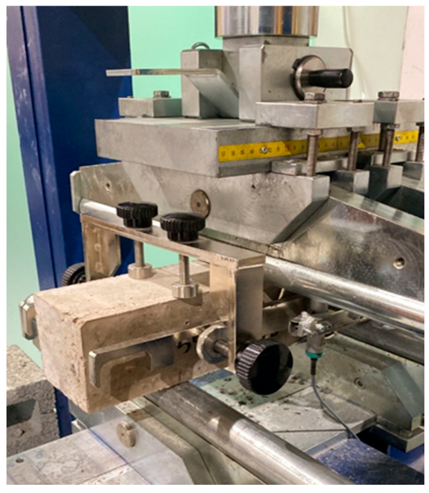
ASTM C39 [57] was followed to evaluate the compressive strength of the geopolymer concrete. The procedure is seen in Figure 1, whereas cube specimens measuring 100 mm × 100 mm × 100 mm were tested with a compression machine rated at 2000 kN. Tests were conducted at 1, 7, and 28 days of curing, with a constant displacement-controlled loading rate of around 0.2 mm/min applied until failure. This enables the assessment of both early-age and long-term strength development in relation to the concrete’s composition.

3.2. Flexural Strength

Prismatic concrete beams with a cross-section of 150 × 150 mm and a span of 500 mm were tested under four-point bending in accordance with ASTM C1609/C1609M [58]. The tests were performed using a servo-controlled machine that applied a constant displacement rate of 0.2 mm/min as displayed in Figure 2. Loading continued until the beam displacement exceeded the minimum limit specified by the standard, defined as L/150. This procedure enabled the evaluation of flexural strength and cracking behavior, which, in turn, enhances the compressive strength.

4. Results and Discussion

4.1. Compressive Behavior

4.1.1. Compressive Strength

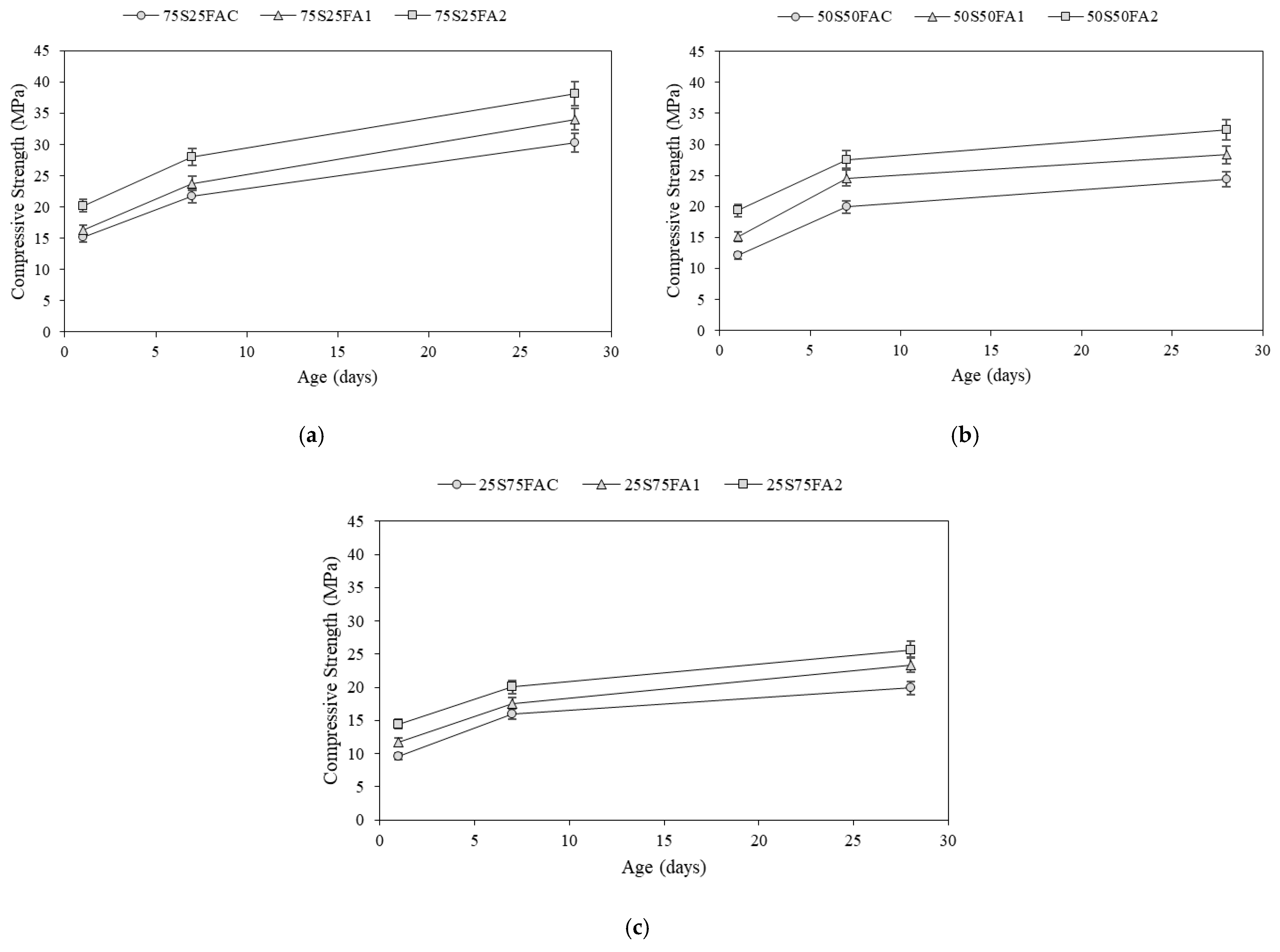
The compressive strength of the specimens varies based on the binder composition and steel fiber content. The steel fiber content in the geopolymer significantly affects the specimen’s compressive strength. As seen in Figure 3 and further detailed in Table 5, there is a positive relationship between the amount of steel fiber in the geopolymer mixture and the mechanical properties of the mixture itself. Whereas, as the steel fiber content in the geopolymer mixture increases, so does the compressive strength, which increases with the mixture’s age and the modulus of elasticity. This trend is observed in all the combinations, regardless of the proportions of slag and fly ash used. However, the mixture containing 75% slag and 25% fly ash achieves the highest compressive strength, irrespective of the steel quantity added. Yet, as the steel fiber content increases from 0% to 1% to 2%, the compressive strength of the sample rises from 30.23 MPa to 33.99 MPa and finally to 38.15 MPa. Similarly, in the mixtures containing equal amounts of slag and fly ash, the compressive strength increases from 24.33 MPa to 28.32 MPa and eventually to 32.39 MPa as the steel fiber content increases from 0% to 1% and then to 2%. Furthermore, mixtures containing 25% slag and 75% fly ash exhibit similar improvements; the compressive strength increases from 19.89 MPa to 23.38 MPa and then to 25.62 MPa with increasing steel fiber content. The increase in compressive strength is due to the steel fiber’s high elastic modulus, fracture strain, and bridging action. Steel fibers increase the compressive strength of materials by effectively bridging cracks and dispersing energy during pullout [1]. As the bond between the steel fibers and the surrounding matrix weakens during the initial stage of crack propagation, the fiber eventually undergoes pullout, where it is gradually extracted from the matrix under applied stress. This pullout action helps dissipate energy and effectively slow down crack propagation, thereby increasing the compressive strength. A previous study by Nakum et al. [59] investigated the microstructure of steel fiber-reinforced geopolymer concrete. Compared to the plain geopolymer concrete matrix, SEM analysis showed that geopolymer concrete with 1% steel fibers exhibited narrower cracks under applied load. This indicates that steel fibers were effective in restricting the progression of cracks in the matrix. Additionally, the SEM micrographs revealed a strong bond between the steel fibers and the matrix, indicating effective load transfer between the two components. However, the addition of steel fibers to geopolymer concrete can have a detrimental impact on workability. Nakum et al. [59] reported that incorporating steel fibers in greater quantities (>0.5%) hinders flowability and workability. When the percentage of steel fibers increased from 0% to 0.5% and from 0.5% to 1.0%, the slump flow was reduced by 6.40% and 11.61%, respectively.
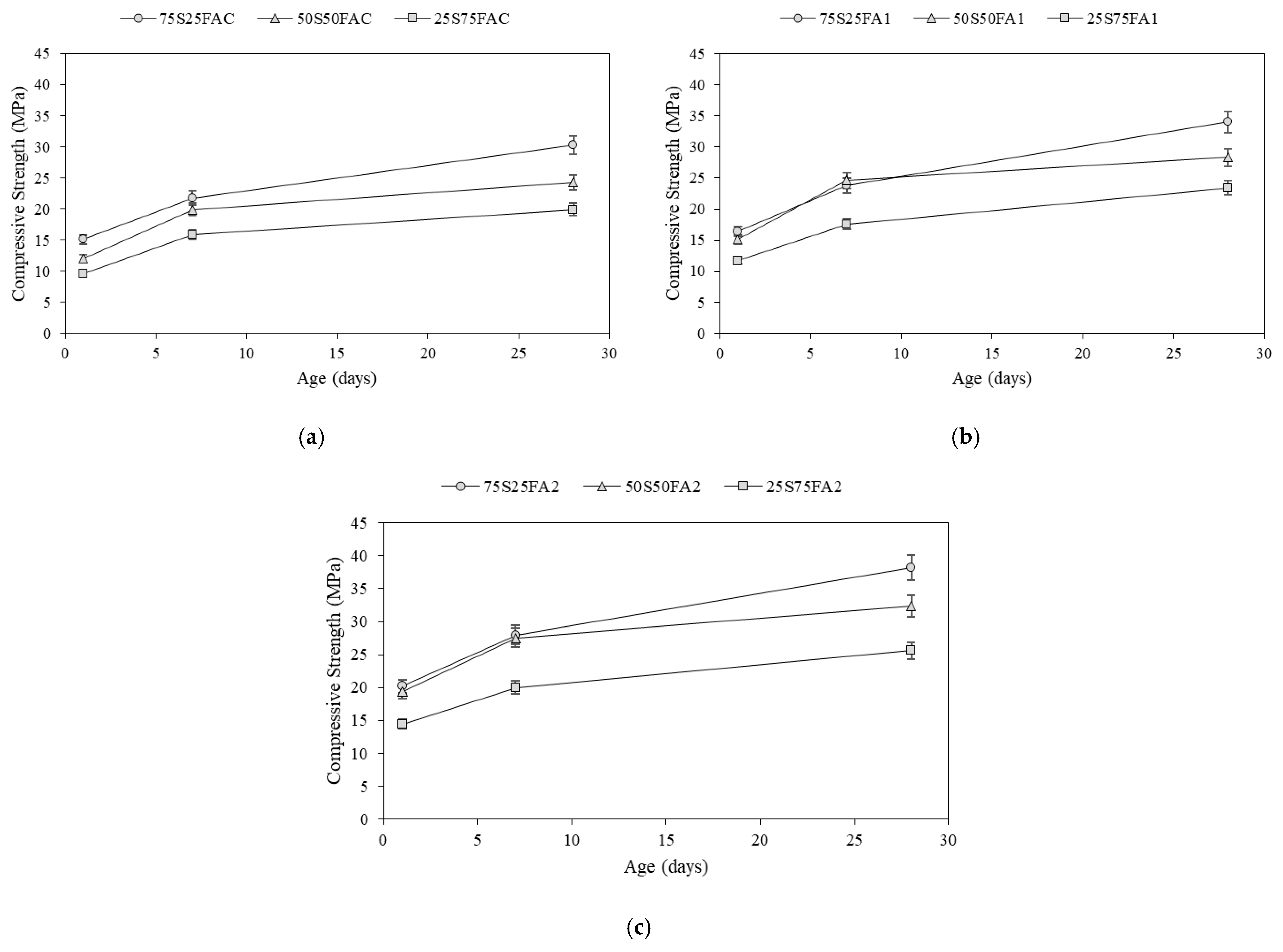
The binder composition has a significant effect on the development of compressive strength, as illustrated in Figure 4. Among the samples tested, those with the highest slag composition exhibited the greatest compressive strength. Specifically, Figure 4a shows that in the absence of steel fibers, sample 75S25FAC achieved a compressive strength of 30.23 MPa in 28 days. In comparison, samples 50S50FAC and 25S75FAC also achieved lower compressive strengths across different fiber contents. For example, specimen 75S25FA1 achieved a 28-day compressive strength of 33.99 MPa, which was higher than the strengths of 28.32 MPa for 50S50FA1 and 23.38 MPa for 25S75FA1, as shown in Figure 4b. The sample with the highest steel fiber volume fraction, at 2% displayed in Figure 4c, also followed this pattern: 75S25FA2 achieved a 28-day compressive strength of 38.15 MPa, which decreased to 32.39 MPa when the slag content was reduced and the fly ash content increased in sample 50S50FA2. Further reduction in slag volume by 25%, accompanied by a 25% increase in fly ash in sample 25S75FA2, resulted in a further decrease in compressive strength to 25.62 MPa at 28 days. Overall, the results demonstrate that increasing the proportion of slag in the binder mixture enhances the compressive strength, whereas reducing the slag content and replacing it with fly ash tends to decrease the compressive strength. This relationship is due to the slag’s reactive nature, which interacts with the activator to produce a C-A-S-H gel, thereby increasing the geopolymer’s compressive strength. Moreover, slag also reduces the material’s total porosity and minimizes the presence of voids. This densification process further increases the geopolymer’s compressive strength. On the other hand, fly ash’s pozzolanic nature decreases its tendency to react with water and the activator, resulting in slower strength development and a lower compressive strength at 28 days [60]. The type of alkaline activator utilized has a significant impact on the mechanical and thermal properties of geopolymer concretes. Rocha [61] reported a higher elastic modulus and enhanced thermal stability at high temperatures for geopolymers activated with potassium silicate compared to those activated with sodium silicate.
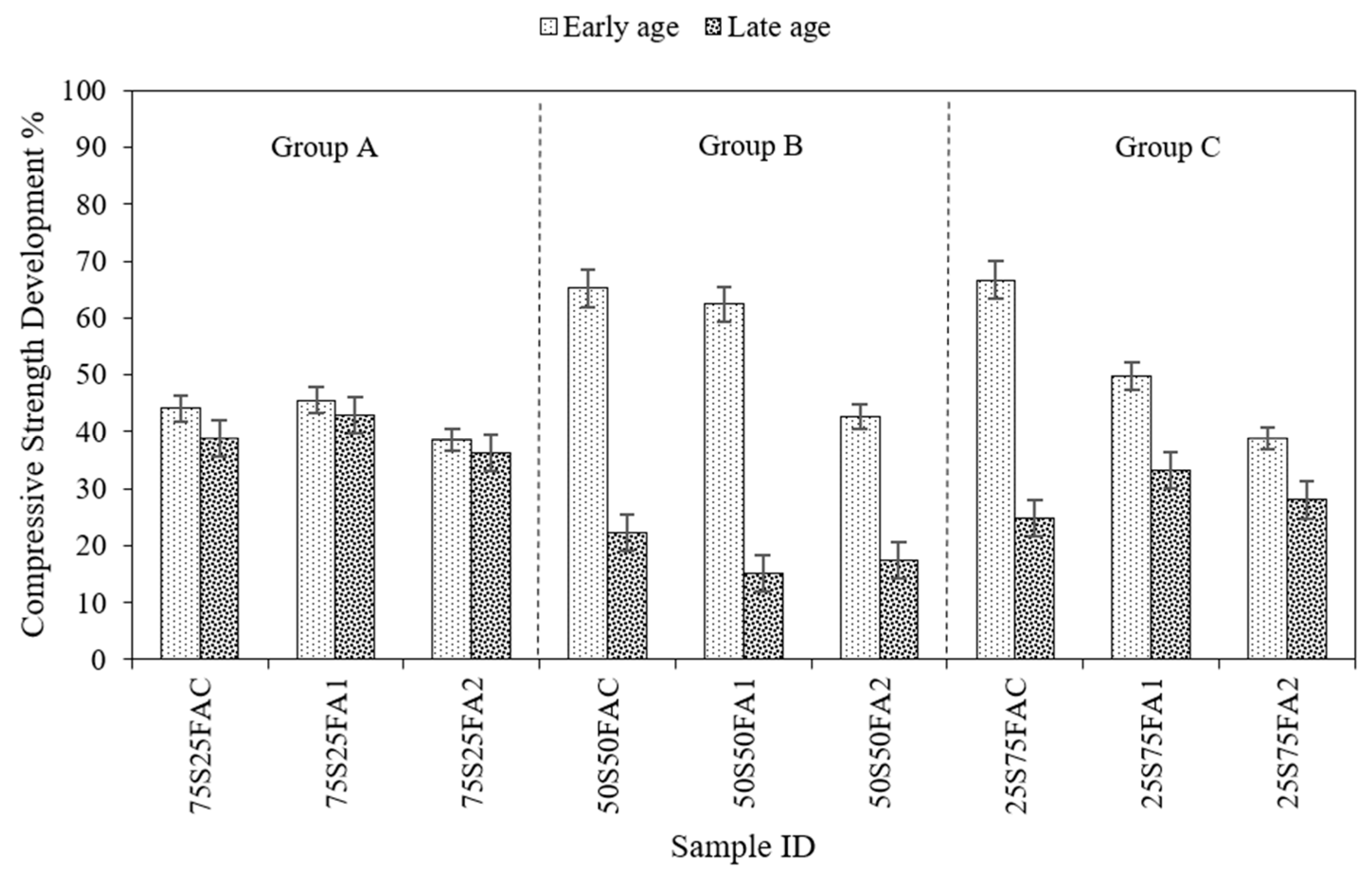
Figure 5 compares early age compressive strength development with late age compressive strength development, highlighting the rate at which the material continues to gain strength over time. Here, early-age compressive strength development refers to the increase in strength that occurs within the first 7 days of curing, while late-age compressive strength development refers to the continued strength gain that occurs beyond 28 days. This distinction highlights both the initial reactivity of the binder system and its long-term performance. The data is divided into three distinct groups based on the binder composition. The geopolymer in Group A is composed of 75% slag and 25% fly ash. In Group B, the geopolymer is composed of 50% slag and 50% fly ash. Finally, the geopolymer in group C is 25% slag and 75% fly ash. Within each group, there are three mixes based on the steel fiber content: 0, 1, and 2%. Geopolymer in Group A, with the largest slag content, exhibits the lowest rate of strength development at early ages and the highest rate of strength development at late ages. Yet, samples in group A exhibit the lowest difference between early-age and late-age compressive strength development. For instance, the percentage difference for compressive strength development in sample 75S25FAC is less than 10%. This is because slag interacts with the activator over an extended period, continuously increasing the geopolymer’s compressive strength. Additionally, the amorphous calcium silicates in the slag only partially react during the early stages of curing. However, these silicates react over time to produce more C-A-S-H gel, thereby increasing the geopolymer’s compressive strength [60,62]. This is consistent with much of the existing research literature. According to [63,64,65,66,67], amorphous calcium silicates present in the slag partially react in the initial stages of curing only. These reactions do not come to an abrupt halt and continue for a very long period. With time, the amorphous calcium silicates gradually react with the surrounding environment, developing calcium-alumino-silicate hydrate (C-A-S-H) gel. This ongoing chemical reaction is responsible for the formation of the material’s microstructure, resulting in increased strength and toughness of the geopolymer.
On the other hand, geopolymer in group C, with the largest fly ash content, exhibits the highest early-age compressive strength development but the lowest late-age compressive strength development, resulting in a significant gap between the early and late-age compressive strength development. Due to the low calcium content in fly ash, fly ash-based geopolymers do not gain strength for a long time, resulting in late-age compressive strength development being significantly lower than at early age. For example, the late age compressive strength development of sample 50S50FA1 is nearly 40% less than that of the early age. The behavior of alkali-activated binders depends on their pore structure. Slag-based binders produce C-A-S-H gels, which in turn create a fine pore network. Fly ash-based binders produce N-A-S-H gel, which produces a coarse pore structure. When fly ash and slag are combined, both types of gel form, which in turn influences the overall pore structure and properties of the binder. Due to their different pore structures, porosity measurements of slag-based binders are less than those of fly ash-based binders [68].

4.1.2. Failure Modes

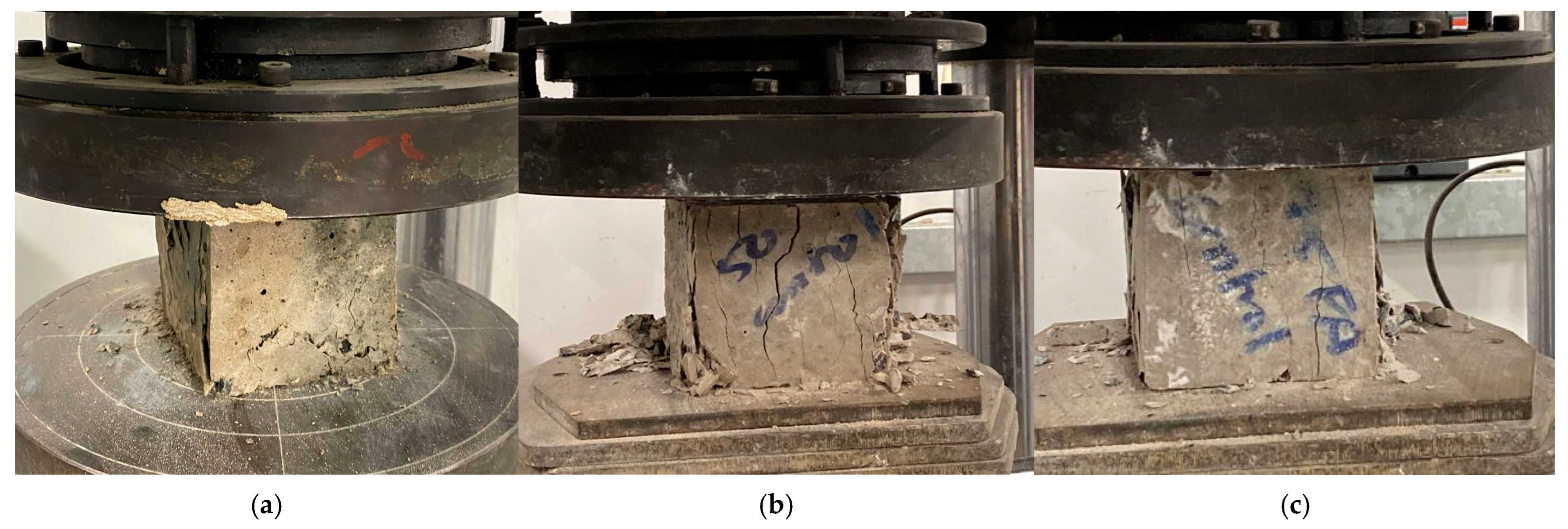
A complex interaction between fiber reinforcement, binder mix, and microstructural integrity controls the compressive strength failure modes of cementitious composites. Under uniaxial compression, geopolymer concrete specimens with varying steel fiber concentrations and slag-to-fly ash ratios exhibited distinct failure behaviors. The mechanical integrity of the matrix and the fibers’ capacity to bridge cracks and postpone eventual failure have an impact on these modes. Figure 6 shows that control specimens in all groups exhibited brittle failure modes, which are characterized by widespread cracking with material ejection from the surface and clearly defined diagonal or vertical shear planes. The 50S50FAC sample, for instance, exhibited a crushing failure along a clearly defined diagonal plane. These control mixes’ low compressive strength values support the unreinforced matrix’s poor capacity to bridge cracks.
The failure behavior of the specimens was considerably changed by the addition of 1% steel fibers. More dispersed cracking and less severe material ejection were observed in samples like 75S25FA1 and 50S50FA1. Fiber bridging increased energy dissipation and fracture propagation, resulting in the development and slow propagation of numerous fine cracks rather than a single dominant shear plane. Additionally, as shown in Figure 7, the higher fiber content leads to more ductile compressive failure modes and improves the post-peak load-carrying capacity. Figure 8 illustrates how the failure patterns become more progressive and ductile at 2% fiber volume. Specimens like 75S25FA2 and 50S50FA2 showed high crack density but maintained core integrity, with less explosive fracture. This behavior is characteristic of highly fibered mixes where fibers provide lateral restraint, improving load redistribution and suppressing brittle fracture. Binder composition also played a crucial role. Group A specimens consistently had higher compressive strength and more cohesive cracking, indicating better matrix density and fiber–matrix interfacial bonding. The denser, slag-rich matrix likely resulted in a more consistent stress distribution and increased crack resistance. However, Group C specimens, such as 25S75FAC and 25S75FA1, showed comparatively weaker matrix-fiber bonding and increased brittleness, as seen by widespread cracking and some surface spalling. This suggests that a high fly ash component could slow down geopolymerization and weaken the composite’s early-age strength, increasing its susceptibility to unstable fracture.

4.2. Flexural Behavior

4.2.1. Load–Displacement Responses

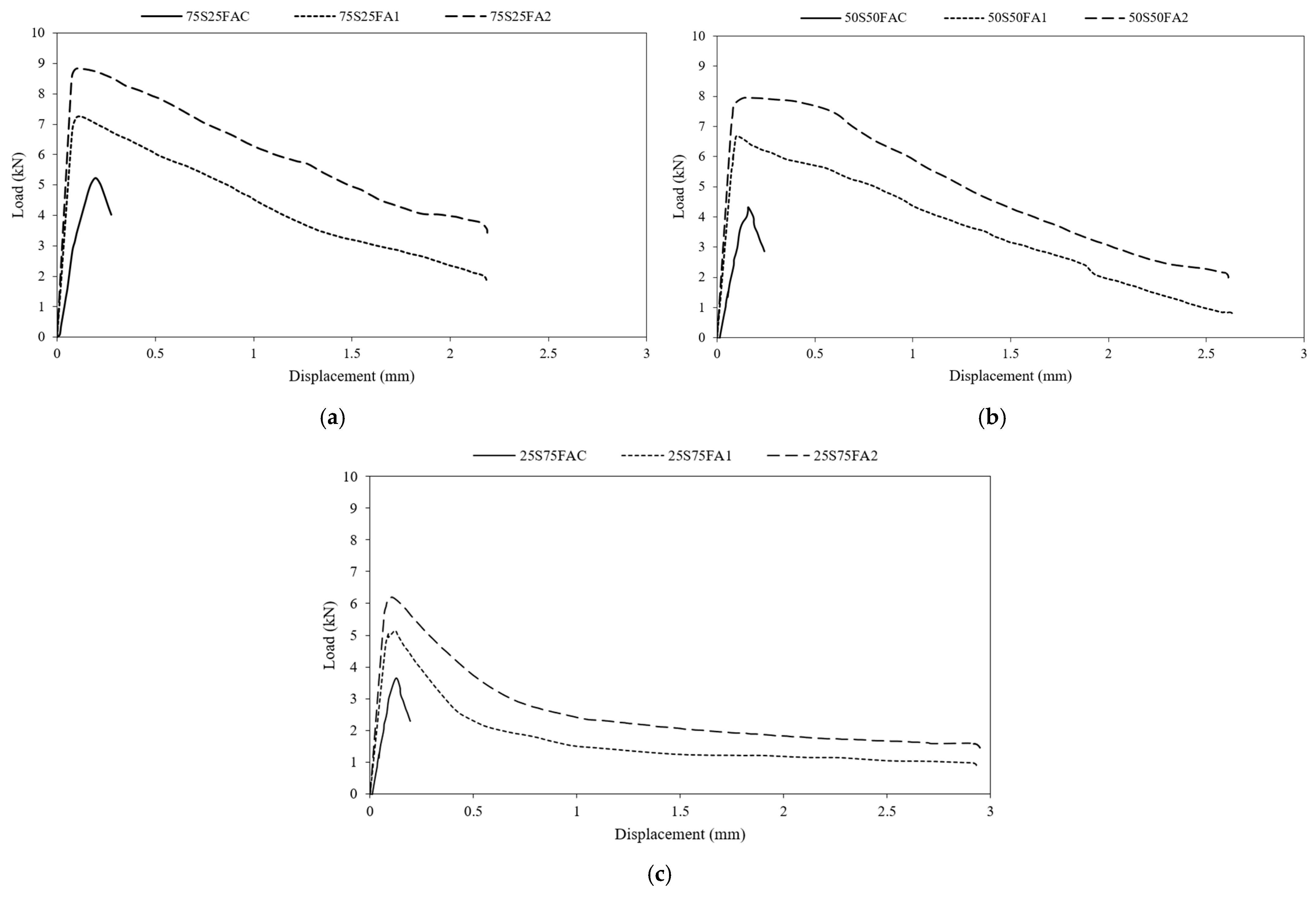
In all groups, the addition of steel fibers significantly increases flexural capacity. The peak loads and their respective ultimate displacements experienced by all beams are summarized in Table 6. In Group A, the control beams failed at about 5.2 kN, whereas beams with 1% and 2% fibers reached roughly 7.25 kN and 8.82 kN, respectively, marking an increase of 40–70%. Ultimate displacement also increased from 0.27 mm for control specimens to 2.2 mm for specimens with 1–2% fiber volume, indicating a greatly enhanced deformation capacity. In practical terms, a higher fiber content yields a more ductile response, which means that the fiber-reinforced specimens sustained large displacements under high loads, whereas the control beam snapped shortly after reaching peak. Group B specimens follow a similar trend. The control beam broke at only 4.31 kN, whereas the addition of 1% and 2% fiber content increased the peak to 6.67 kN and 7.95 kN, respectively. The ultimate displacement rose dramatically from 0.24 mm for the control specimens to 2.6 mm for those with fibers, representing an over tenfold increase in displacement. Thus, as in Group A, adding fibers greatly enhances the flexural capacity and ductility. The 1% fiber mix already carries most of the gain; 2% gives a modest further increment. Group C again shows the same trend of fiber enhancement. Peak load rises from 3.65 kN for control beams, to 5.12 kN for 1% fiber, and 6.22 kN for 2% fiber, an increase of 40% and 70%. Remarkably, ultimate displacement jumps from only 0.19 mm for control to 2.9 mm for beams reinforced with fibers, marking a more than 15-fold increase. This indicates that the fibers’ impact on ductility is especially remarkable in the weaker fly ash matrix, as the control mix was extremely brittle; however, the addition of 2% fiber gives it a substantial displacement capacity. The proportional gains in ductility and energy absorption appear most prominent in this group.
All load–displacement curves start with an initial linear segment up to the first crack, as shown in Figure 9. The control slag-rich beam in Group A cracks at a low displacement of 0.27 mm and then drops sharply in load, exhibiting brittle failure. In contrast, the 1% and 2% fiber beams crack at higher loads and then exhibit a more gradual post-peak softening. The curves for fiber-reinforced specimens exhibit a pronounced tail after the peak, as the load decreases slowly over several millimeters of displacement following the first crack. This tail is especially evident at 2% fiber, where the beam carries nearly half its peak load even at large displacements. This behavior reflects strain-hardening or multiple-cracking action; steel fibers bridge the cracks as they form, allowing the beam to continue carrying load while the cracks widen. Steel fibers enable geopolymer to become more ductile by bridging and preventing internal cracking from developing, thereby promoting the formation of a series of small cracks that extend throughout the structure rather than the material failing abruptly along a single large crack. By releasing more energy prior to failure, this tendency increases the overall toughness and resistance of the material [14,50,69].
The control beams in Group B exhibit a linear response up to a brittle peak at low displacement, followed by an abrupt drop in load. In contrast, the 1% and 2% fiber beams crack at higher loads and then descend into a long, low-slope branch. The 2% fiber curve notably features a flat tail from approximately 1 mm to 9 mm displacement, indicating significant residual capacity after the peak. This means the fiber-reinforced beams develop multiple small cracks rather than one large fracture. Early behavior, below 0.2–0.3 mm, is elastic in all cases; however, beyond the first cracking, the fiber mixes exhibit much slower strength decay. In Group C, the control beam cracks early and collapses almost immediately. With 1% and 2% fibers, the beams crack at higher loads but then show a very gradual softening branch. The 2% fiber curve is particularly flat after a 1 mm displacement, sustaining approximately 60% of the peak load. The elastic response is nearly identical for all mixes, but the fiber-reinforced curves do not drop off sharply; instead, they exhibit a long tail of slowly declining load. This is clear evidence of extensive fiber pullout and multiple cracking.
Across all three binder compositions, the inclusion of steel fibers significantly enhanced crack resistance and energy absorption. In unreinforced specimens, cracks formed early and propagated rapidly, resulting in brittle failure. With 1% and 2% fiber additions, the concrete developed multiple fine cracks instead of a single dominant one, as the fibers bridged the crack faces and redistributed tensile stresses. This bridging action delayed crack widening and allowed the beams to sustain load beyond the initial failure point, leading to a more ductile response. The area under the load–displacement curve, an indicator of energy absorption, increased substantially with fiber content, especially in the 2% mixes. Notably, Group C, though weakest in base matrix strength, showed the most significant proportional gains in ductility, highlighting the compensatory effect of fibers in brittle matrices.

4.2.2. Flexural Strength

The flexural strength behavior of geopolymer concrete specimens varied significantly across binder compositions and steel fiber contents. The flexural strength values were computed using the standard formula:
f = P L b d 2 ,
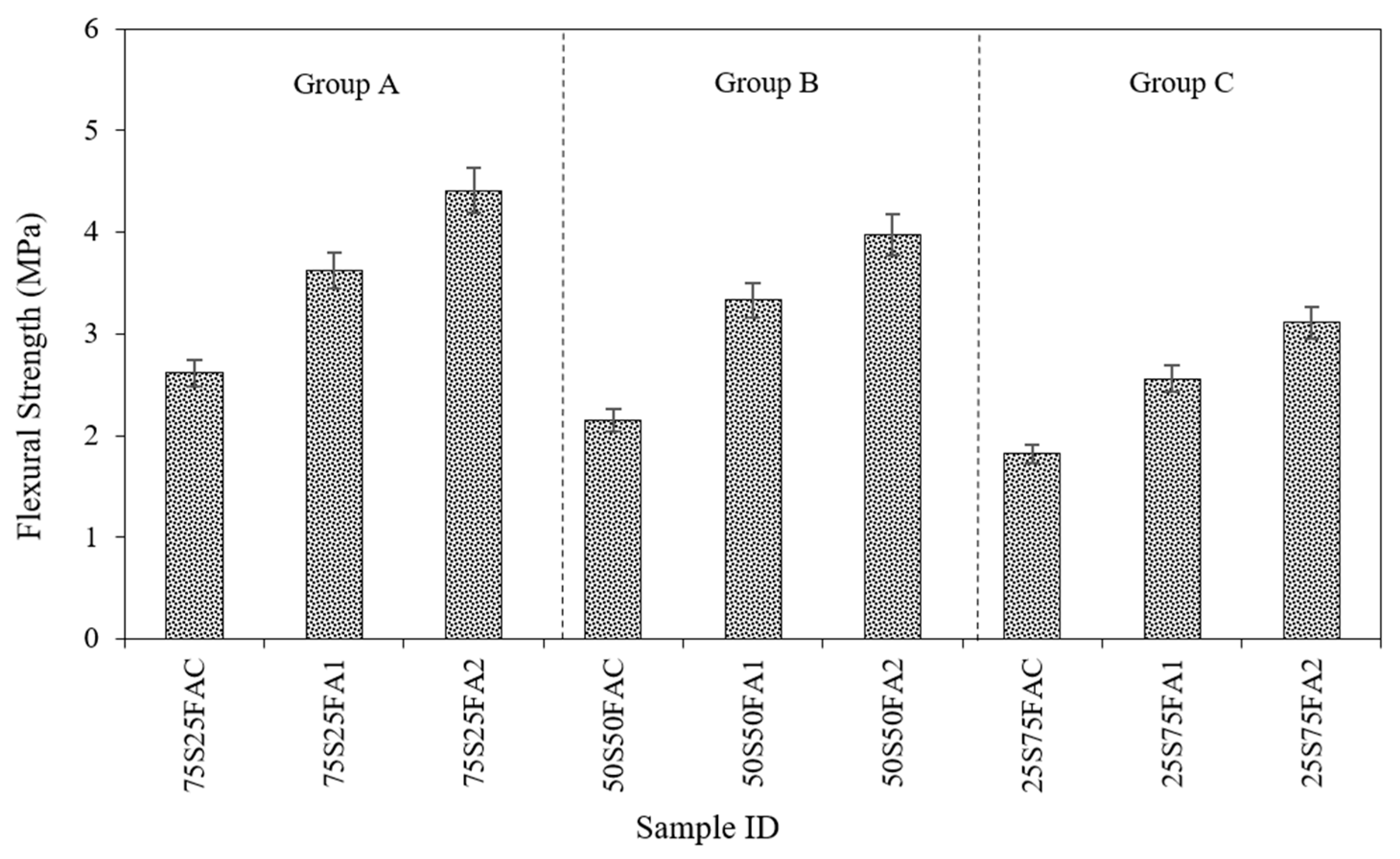
where P is the peak load from the flexural test, L is the span length, b is the width of the beam, and d is its depth. These calculated values represent the bending capacity of each beam at 28 days, enabling a comparative assessment across different binder compositions and fiber volumes. In general, an increase in steel fiber volume resulted in a notable improvement in flexural strength across all binder groups, although the extent of enhancement and the base strength level depended heavily on the slag-to-fly ash ratio. Group A demonstrated the highest flexural strength among all groups. The control sample reached 2.62 MPa, which increased substantially to 3.63 MPa at 1% fiber and peaked at 4.41 MPa with 2% fiber, as shown in Table 7. The first 1% fiber provided a larger incremental gain than the second 1%. This trend reflects the well-known crack-bridging action of steel fibers, where the initial addition of fibers dramatically increases toughness and splits forces across microcracks. Furthermore, the absolute increase from 0% to 2% fiber was 1.80 MPa, reflecting a strong positive influence of fiber reinforcement. This group benefited from the high slag content, which likely contributed to a denser and more cohesive matrix, allowing the steel fibers to perform effectively in bridging cracks and enhancing tensile resistance. Group B displayed a similar trend, though with slightly lower values compared to Group A. The control mix reported a compressive strength of 2.16 MPa, which improved to 3.34 MPa at 1% fiber and 3.98 MPa at 2% fiber. The increase from 0% to 2% was 1.83 MPa, closely matching the improvement seen in Group A, although the final values remained marginally lower. This suggests that while steel fibers provide consistent improvement, the matrix’s initial strength, influenced by binder composition, still governs the overall performance ceiling. Group C showed the lowest baseline and demonstrated the most significant improvement in flexural strength. The control specimen achieved only 1.83 MPa, increasing to 2.56 MPa with 1% fiber and reaching 3.11 MPa at 2% fiber. While the trend of increasing strength with fiber content was still evident, the total gain of 1.28 MPa from 0% to 2% was less than that of the other groups. This likely reflects the lower reactivity and slower strength development associated with a high fly ash content, resulting in a weaker matrix that limits the effectiveness of fibers. Across all groups, the enhancement from 0% to 1% fiber consistently produced a larger gain in flexural strength compared to the increase from 1% to 2%. This suggests that the first increment of fibers has the most substantial impact on crack resistance and load distribution. In summary, Group A outperformed the others at all fiber levels, indicating that a stronger matrix enhances the effectiveness of fiber reinforcement. Group C remained the weakest, both at baseline and after the addition of fiber. The variation in results is further evident from the bar graphs in Figure 10. These results underscore the importance of binder composition in establishing base strength, while fiber reinforcement acts as a significant strength enhancer, particularly when supported by a denser and more reactive matrix.

4.2.3. Initial Stiffness

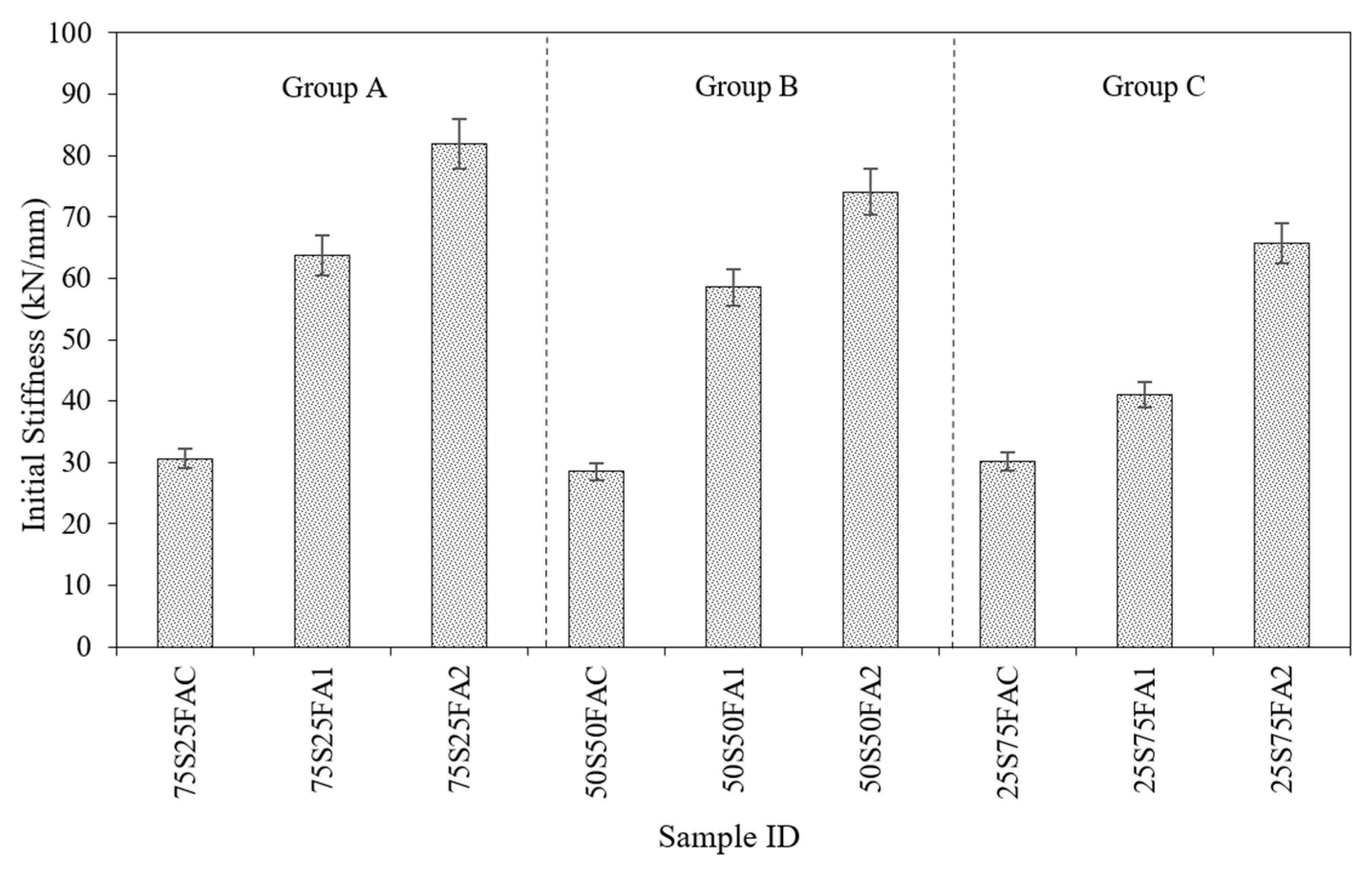
Initial stiffness is defined as the slope of the linear-elastic portion of the load–displacement curve, typically obtained from four-point bending tests. It represents the beam’s resistance to deformation under small loads, before any cracking occurs. In this study, the initial stiffness was calculated in units of kN/mm, using the tangent to the initial straight segment of each beam’s load–displacement response. In cementitious or geopolymer composites, higher initial stiffness typically indicates a denser, more cohesive matrix and effective fiber engagement in the elastic phase. In Group A, the control mix had an initial stiffness of 30.64 kN/mm, as shown in Table 8. With 1% fiber, stiffness rose sharply to 63.73 kN/mm, and further increased to 81.88 kN/mm at 2% fiber. This represents an increase of over 167% from 0% to 2%, indicating that steel fibers substantially improve the elastic-phase rigidity, likely due to enhanced microcrack control and improved load distribution. The control mix of Group B exhibited the lowest baseline stiffness, at 28.52 kN/mm. Adding 1% fiber increased stiffness to 58.55 kN/mm, and 2% fiber yielded 74.11 kN/mm. The trend mirrors that of Group A, with a steep rise from 0% to 1%, followed by a smaller but significant increase at 2%. The percentage increase from 0% to 2% fiber is approximately 160%. In Group C, the control sample had a stiffness of 30.19 kN/mm, which is comparable to that of Group A. However, the increase with fiber addition was more gradual, 40.99 kN/mm at 1% and 65.77 kN/mm at 2%. Unlike A and B, where the most significant jump occurred at the first fiber increment, Group C exhibited a larger relative gain between 1% and 2%, indicating that higher fiber content was needed to improve stiffness in the more fly ash-rich matrix noticeably.
When comparing the control mixes of all groups, the stiffness values are similar: 30.64 kN/mm for Group A, 28.52 kN/mm for Group B, and 30.19 kN/mm. The slight differences suggest that the binder ratio alone has a limited impact on initial stiffness in the absence of fibers. At 1% and 2% fiber, however, the influence of binder ratio becomes clearer. For both fiber contents, Group A consistently had the highest stiffness, followed by Group B, then Group C, as clearly seen in Figure 11. This reinforces the idea that slag-rich matrices provide a more effective load transfer medium, allowing the steel fibers to engage more efficiently and restrict early-stage deformations. Thus, steel fibers enhance stiffness by bridging microcracks and sharing tensile loads early in the load cycle. However, their effectiveness is modulated by the matrix’s ability to anchor them, which appears strongest in slag-rich mixes. Besides flexural stiffness, long-term creep and drying shrinkage are key factors affecting the serviceability of fiber-reinforced geopolymer composites. Studies on fly ash-based geopolymer concrete show that drying shrinkage remains low over time, typically below 400 microstrain after one year [70]. The basic mean creep, measured as the ratio of creep strain to elastic strain under sustained loading, was found to be up to 45 percent lower in steam-cured geopolymer concrete compared to equivalent 40 MPa ordinary Portland cement concrete. These findings indicate that geopolymer matrices exhibit reduced load-dependent deformations, and the inclusion of fibers can further enhance dimensional stability by limiting crack formation and distributing stress more evenly [70].

4.2.4. Toughness

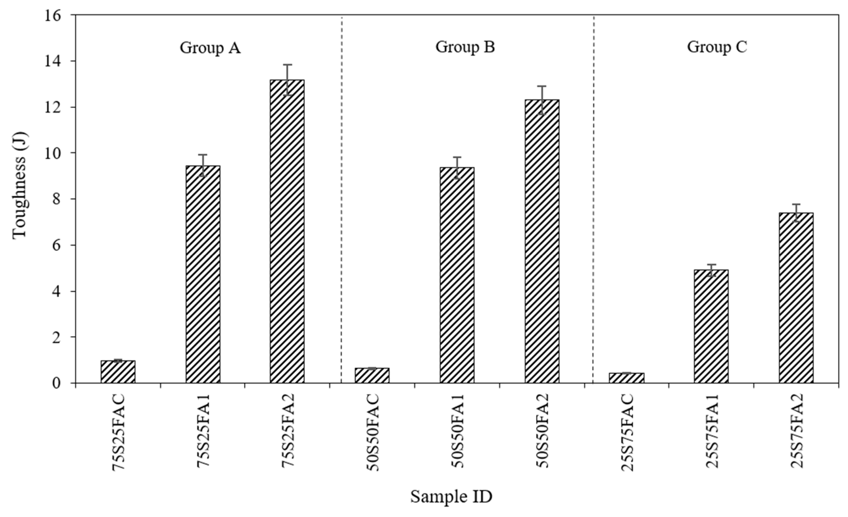
Toughness, in the context of flexural testing, refers to the total energy absorbed by a specimen before failure, which is quantified as the area under the load–displacement curve. It is a direct indicator of a material’s capacity to resist fracture and sustain deformation after cracking. Tougher materials can absorb more energy through mechanisms such as crack bridging, fiber pullout, and post-crack ductility. In this study, toughness was obtained according to ASTM C1018, which is the area under the curve up to a deflection of L/150, where L is the clear prism length. The calculated toughness values of all beams are summarized in Table 9. As seen in Figure 12, group A exhibited the highest toughness among all groups at every fiber content level. The control sample showed a low toughness of 0.96 J, typical of brittle fracture in plain geopolymer concrete. With 1% steel fiber, toughness jumped to 9.45 J, and at 2% fiber, it further increased to 13.18 J, representing a 39.5% gain over the 1% mix. These increases are attributed to fiber bridging and post-crack load transfer, which prolong deformation and absorb more energy. This trend confirms that even moderate fiber addition can greatly enhance toughness. Steel fibers enhance the flexural toughness of geopolymer by facilitating the development of a large number of fine cracks, thereby changing the mode of failure from brittle to ductile. This enables the geopolymer to resist higher loads after cracking and absorb more energy during the development of cracks and post-peak load, thus increasing its overall toughness and durability [71,72,73]. Group B also experienced significant improvements in toughness. The control sample had the lowest initial toughness of 0.64 J, increasing to 9.36 J at 1% fiber and to 12.87 J at 2%, a 37.5% increase from 1%. Interestingly, the 2% fiber mix in this group approached the toughness of Group A’s 2% specimen, indicating that the 50/50 binder may offer an optimal balance between strength and ductility. This further suggests that an intermediate slag content can provide sufficient matrix integrity to work with steel fibers for energy absorption. Group C began with the lowest initial toughness of 0.438 J. At 1% fiber, toughness rose to 4.91 J, and at 2% fiber, it reached 7.40 J, a 50.7% gain over the 1% mix. While absolute values are lower than in other groups, the relative improvements are significant. This confirms that even in fly ash–rich, low-reactivity binders, fiber reinforcement can substantially boost post-crack energy absorption. However, the reduced matrix strength likely limits the full potential of the fiber–matrix interaction, particularly in terms of anchorage and crack-bridging effectiveness. In all groups, the addition of steel fibers significantly increases toughness by enhancing energy absorption through crack bridging and post-crack load retention. As fibers pull out, they consume energy and maintain load capacity, yielding a much more ductile response. These observations highlight significant gains in toughness with fibers. Overall, Group B’s balanced binder achieved the highest toughness at each fiber level, while Group C’s low-slag mix was weakest, reflecting the interplay of binder strength and fiber toughening.

4.2.5. Failure Modes

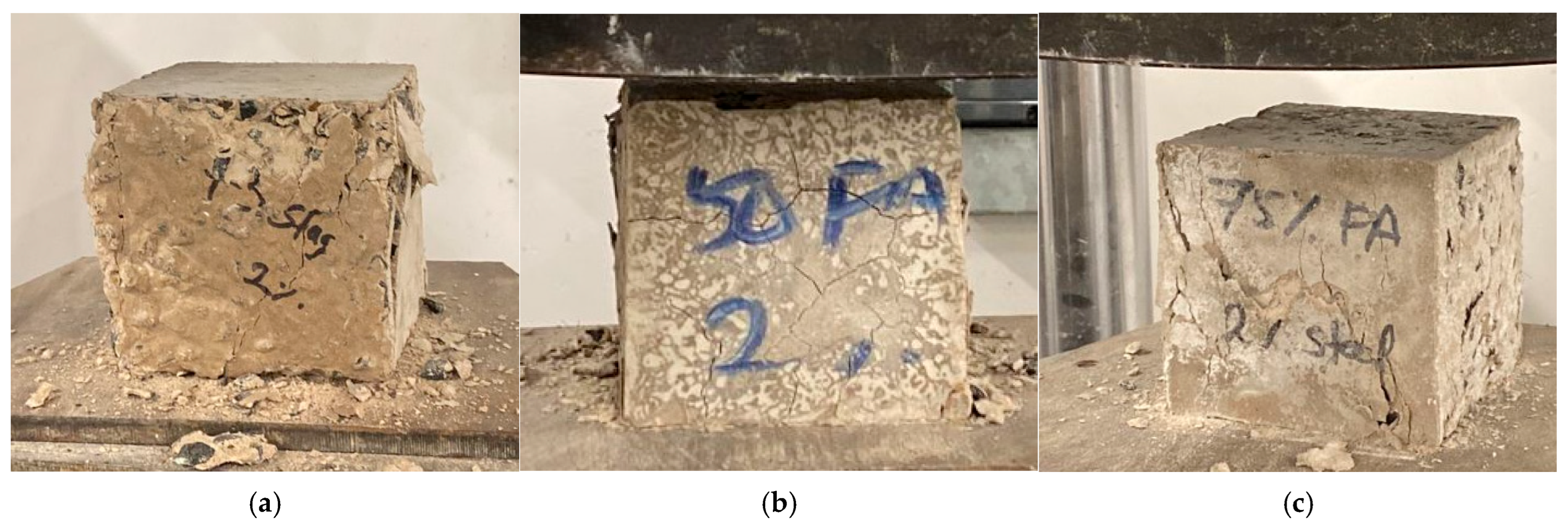
Binder composition and the volume fraction of steel fibers directly influence the failure mode of the beams under bending, transitioning from brittle fracture to ductile cracking as the mix and reinforcement vary. Regardless of binder composition, control beams experienced brittle flexural splitting. Under flexural loading, these specimens exhibit a single, dominant vertical crack at the tensile face of the midspan that propagates through the depth of the beam, shown in Figure 13, leading to a sudden break with no significant post-peak load resistance. The controls of Group A have higher stiffness and strength, causing them to fail explosively once cracking initiates. Group C specimens, while weaker, show slightly more displacement at failure but still fail in a single-crack brittle manner. This concludes that unreinforced geopolymer concrete lacks tensile ductility and fails by splitting-type fracture due to low strain capacity in tension. The lack of post-crack load resistance or energy dissipation is typical of unreinforced geopolymer matrices, which generally possess low tensile capacity. While the balanced binder ratio may offer improved workability and moderate compressive strength, it alone is insufficient to prevent brittle fracture in the absence of fibers.
When steel fibers are added, the failure mode transitions significantly. Instead of one dominant crack, the tensile region forms multiple fine vertical cracks shown in Figure 14a,b, spaced across the midspan, each partially opened and bridged by fibers. This phenomenon is referred to as multi-cracking with fiber bridging and is the hallmark of ductile flexural failure in fiber-reinforced cementitious or geopolymer concretes. Fibers hinder crack propagation and carry tensile stress across cracks through pullout or partial rupture, allowing for stable crack growth and post-peak load-carrying capacity. The degree of multi-cracking improves with higher slag content and higher fiber volume, resulting in increased energy absorption and enhanced crack control. In Group C, specimens reinforced with 1% and 2% fiber exhibit a unique hybrid failure mode, where one or two dominant vertical cracks open significantly, as shown in Figure 14c, but are still held together by the fibers. Concrete spalls at the edges, and the crack widens considerably. This reflects a localized ductile fracture, where fiber bridging is present but not sufficient to induce multiple cracking across the span. This is common in matrices with lower stiffness and tensile strength, where crack localization occurs earlier, and fibers undergo concentrated pullout over a few zones rather than distributing across multiple cracks. The fiber–matrix interaction here delays failure and improves energy absorption, but the lack of distributed cracking limits toughness compared to more balanced binder systems.

5. Conclusions

The study examined the impact of steel fibers and various binder compositions on the structural integrity and mechanical properties of geopolymer concrete. The experimental program included conducting compressive strength tests at various curing ages: 1 day, 7 days, and 28 days, to evaluate the early and late-age performance of geopolymer concrete. Furthermore, the flexural behavior of the specimens was investigated using four-point bending tests to analyze their ability to resist bending stresses, as well as crack initiation and propagation under load. The experimental results revealed the following conclusions:
  • Increasing steel fiber content from 0% to 1% to 2% increases the compressive strength and modulus of elasticity, regardless of the slag to fly ash ratio. This is because steel fibers bind cracks together and prevent their rapid spread. Throughout the pullout process, the fibers absorb energy, reducing crack formation and increasing the material’s strength.
  • Binder composition plays a role in the development of compressive strength in geopolymers. Samples with higher slag content show greater compressive strength compared to those with more fly ash. This is due to slag’s higher reactivity, which forms a strength-contributing C-A-S-H gel and reduces porosity. In contrast, fly ash reacts more slowly and less effectively with the activator, resulting in lower strength development.
  • Mixtures with more slag exhibit minimal differences between early and late-age compressive strength development. This is owing to slag’s prolonged reactivity and long-term production of C-A-S-H gel. In contrast, mixtures with more fly ash exhibit a significant difference in compressive strength development between early and late ages, primarily due to the low calcium concentration in fly ash, which reduces reactivity and strength development.
  • Increasing steel fiber volume from 0% to 2% consistently improved both compressive and flexural strength across all binder ratios. For example, in the 75S25FA group, compressive strength increased by 28.8% and flexural strength by 70.4% with 2% fiber addition compared to the control.
  • At constant fiber content, increasing slag content enhanced strength performance. For example, at 2% fiber, compressive strength increased from 25.62 MPa for 25S75FA2 to 38.15 MPa for 75S25FA2, while flexural strength rose from 12.81 MPa to 19.08 MPa.
  • The most significant strength gains were observed when high slag content was combined with fiber reinforcement, indicating a synergistic effect. The 75S25FA2 sample achieved the highest compressive and flexural strengths, emphasizing the importance of both a reactive binder and fiber bridging action.
  • Steel fibers significantly enhanced crack resistance, flexural strength, stiffness, and toughness across all binder compositions by bridging cracks; mixes with 75% slag consistently outperformed other mixes, indicating that stronger matrices enable more effective fiber engagement, while mixes with 75% fly ash remained the weakest even after fiber addition due to reduced matrix-fiber interaction and lower strength.
Although slag-rich concretes produce the highest results, the process required to produce and extract slag consumes high energy levels, generates significant greenhouse gas emissions, and incurs high costs. These factors can substantially reduce the potential environmental benefits of geopolymer concrete, challenging its sustainability compared to conventional materials. The absence of standardized testing methods and quality control for geopolymer concretes hinders their application in fields. Existing research evaluated the influence of binder composition, activator concentration, and curing methods. However, the performance of geopolymer concrete depended on the methods adopted by each study. To ensure consistent performance on site, standards and codes should be developed for geopolymer concrete. Additionally, the adoption of geopolymer concrete in site applications poses safety challenges due to the highly alkaline activators. Standards regarding safety should outline guidelines for handling chemicals safely on construction sites, which may require special equipment and trained workers.
This study examines the mechanical behavior of geopolymer concrete with varying steel fiber concentrations and different slag-to-fly ash ratios. The inconsistent chemical composition and quality of industrial by-products are limitations of this work, as they affect the consistency of the results. Additionally, the study focuses on straight steel fibers and excludes the effects of other fiber types, such as glass or synthetic fibers, as well as fiber geometry, length, and orientation, all of which may affect the geopolymer’s behavior. Moreover, the geopolymer’s lifespan and durability are uncertain in various environmental conditions, as its long-term performance under harsh conditions, such as freeze–thaw cycles, chemical attacks, or extreme temperatures, has not been thoroughly analyzed. A future research direction would be to investigate the impact of various fiber types and geometries on geopolymers under diverse environmental conditions. Additionally, compare the sustainability and environmental footprint of geopolymer concrete with that of conventional concrete by conducting in-depth life cycle assessments.

Author Contributions

Conceptualization, A.T., R.A. and M.A.; methodology, A.T., R.A. and M.A.; software, R.A.; validation, R.A.; formal analysis, R.A. and H.Z.; investigation, R.A., H.Z., D.E., A.T. and M.A.; resources, R.A., H.Z., D.E., A.T. and M.A.; data curation, R.A., H.Z. and D.E.; writing—original draft preparation, R.A., H.Z. and D.E.; writing—review and editing, A.T. and M.A.; visualization, R.A., H.Z. and D.E.; supervision, A.T. and M.A.; project administration, A.T. and M.A.; funding acquisition, A.T. and M.A. All authors have read and agreed to the published version of the manuscript.

Funding

This research was financially supported by the Open Access Program (OAP) at the American University of Sharjah (AUS).

Data Availability Statement

The raw data supporting the conclusions of this article will be made available by the authors on request.

Acknowledgments

The authors greatly appreciate financial support from AUS. This paper represents the opinions of the authors and does not mean to represent the position or opinions of AUS.

Conflicts of Interest

The authors declare no conflicts of interest.

References

  1. Zhang, P.; Wang, J.; Li, Q.; Wan, J.; Ling, Y. Mechanical and fracture properties of steel fiber reinforced geopolymer concrete. Sci. Eng. Compos. Mater. 2021, 28, 299–313. [Google Scholar] [CrossRef]
  2. AlHamaydeh, M.; Amin, F. Axial Load-Bending Moment (P-M) Interaction of Geopolymer Fiber-Reinforced Concrete Slender Columns Reinforced with Steel, Glass Fiber-Reinforced Polymer, or Hybrid Double Layer. ACI Struct. J. 2024, 121, 63–73. [Google Scholar] [CrossRef]
  3. AlHamaydeh, M.; Amin, F. Data for Interaction Diagrams of Geopolymer FRC Slender Columns with Double-Layer GFRP and Steel Reinforcement. Data 2021, 6, 43. [Google Scholar] [CrossRef]
  4. Islam, A.; Alengaram, U.J.; Jumaat, M.Z.; Ghazali, N.B.; Yusoff, S.; Bashar, I.I. Bashar, Influence of steel fibers on the mechanical properties and impact resistance of lightweight geopolymer concrete. Constr. Build. Mater. 2017, 152, 964–977. [Google Scholar] [CrossRef]
  5. Amran, Y.H.M.; Alyousef, R.; Alabduljabbar, H.; El-Zeadani, M. Clean production and properties of geopolymer concrete; A review. J. Clean. Prod. 2020, 251, 119679. [Google Scholar] [CrossRef]
  6. Rajini, B.; Sashidhar, C. Prediction mechanical properties of GGBS based on geopolymer concrete by using analytical method. Mater. Today Proc. 2019, 19, 536–540. [Google Scholar] [CrossRef]
  7. Lee, W.H.; Wang, J.H.; Ding, Y.C.; Cheng, T.W. A study on the characteristics and microstructures of GGBS/FA based geopolymer paste and concrete. Constr. Build. Mater. 2019, 211, 807–813. [Google Scholar] [CrossRef]
  8. Bouaissi, A.; Li, L.Y.; Abdullah, M.M.A.B.; Bui, Q.B. Mechanical properties and microstructure analysis of FA-GGBS-HMNS based geopolymer concrete. Constr. Build. Mater. 2019, 210, 198–209. [Google Scholar] [CrossRef]
  9. Gopalakrishna, B.; Dinakar, P. Mix design development of fly ash-GGBS based recycled aggregate geopolymer concrete. J. Build. Eng. 2022, 63, 105551. [Google Scholar] [CrossRef]
  10. Trivedi, S.S.; Ansari, F.; Das, B.; Barbhuiya, S. Effect of CO2 curing on phase compositions of nano silica blended cementitious mortar partially replaced with carbonated recycled fine aggregates. Constr. Build. Mater. 2025, 491, 142789. [Google Scholar] [CrossRef]
  11. Alnahhal, M.F.; Alengaram, U.J.; Jumaat, M.Z.; Alqedra, M.A.; Mo, K.H.; Sumesh, M. Evaluation of Industrial By-Products as Sustainable Pozzolanic Materials in Recycled Aggregate Concrete. Sustainability 2017, 9, 767. [Google Scholar] [CrossRef]
  12. Sumesh, M.; Alengaram, U.J.; Jumaat, M.Z.; Mo, K.H.; Alnahhal, M.F. Incorporation of nano-materials in cement composite and geopolymer based paste and mortar—A review. Constr. Build. Mater. 2017, 148, 62–84. [Google Scholar] [CrossRef]
  13. Sharmin, A.; Alengaram, U.J.; Jumaat, M.Z.; Yusuf, M.O.; Kabir, S.M.A.; Bashar, I.I. Influence of source materials and the role of oxide composition on the performance of ternary blended sustainable geopolymer mortar. Constr. Build. Mater. 2017, 144, 608–623. [Google Scholar] [CrossRef]
  14. Zheng, Y.; Zhang, W.; Zheng, L.; Zheng, J. Mechanical properties of steel fiber-reinforced geopolymer concrete after high temperature exposure. Constr. Build. Mater. 2024, 439, 137394. [Google Scholar] [CrossRef]
  15. Markou, G.; AlHamaydeh, M. 3D Finite Element Modeling of GFRP-Reinforced Concrete Deep Beams without Shear Reinforcement. Int. J. Comput. Methods 2018, 15, 1850001. [Google Scholar] [CrossRef]
  16. AlHamaydeh, M.; Orabi, M.A. Experimental quantification of punching shear capacity for large-scale GFRP-reinforced flat slabs made of synthetic fiber-reinforced self-compacting concrete dataset. Data Brief 2021, 37, 107196. [Google Scholar] [CrossRef]
  17. Zuaiter, M.; Khalil, A.; Elkafrawy, M.; Hawileh, R.; AlHamaydeh, M.; Ayman, A.; Kim, T.-Y. Effect of blending GGBS and silica fume on the mechanical properties of geopolymer concrete. Sci. Rep. 2025, 15, 9091. [Google Scholar] [CrossRef] [PubMed]
  18. Abdullah, M.M.A.; Hussin, K.; Bnhussain, M.; Ismail, K.N.; Ibrahim, W.M.W. Mechanism and Chemical Reaction of Fly Ash Geopolymer Cement—A Review. Int. J. Pure Appl. Sci. Technol. 2011, 6, 35–44. [Google Scholar]
  19. Juenger, M.C.G.; Winnefeld, F.; Provis, J.L.; Ideker, J.H. Advances in alternative cementitious binders. Cem. Concr. Res. 2011, 41, 1232–1243. [Google Scholar] [CrossRef]
  20. Danish, A.; Ozbakkaloglu, T.; Mosaberpanah, M.A.; Salim, M.U.; Bayram, M.; Yeon, J.H.; Jafar, K. Sustainability benefits and commercialization challenges and strategies of geopolymer concrete—A review. J. Build. Eng. 2022, 58, 105005. [Google Scholar] [CrossRef]
  21. Gollakota, A.R.K.; Volli, V.; Shu, C.M. Progressive utilisation prospects of coal fly ash: A review. Sci. Total Environ. 2019, 672, 951–989. [Google Scholar] [CrossRef]
  22. Talakokula, V.; Vaibhav; Bhalla, S. Non-Destructive Strength Evaluation of Fly ash Based Geopolymer Concrete Using Piezo Sensors. Procedia Eng. 2016, 145, 1029–1035. [Google Scholar] [CrossRef]
  23. Poudenx, P. The effect of transportation policies on energy consumption and greenhouse gas emission from urban passenger transportation. Transp. Res. Part A Policy Pract. 2008, 42, 901–909. [Google Scholar] [CrossRef]
  24. World Academy of Science, Engineering and Technology. 116R-90 ACI, Cement and Concrete Terminology; World Academy of Science, Engineering and Technology: Istanbul, Turkey, 2000. [Google Scholar]
  25. Suresh, D.; Nagaraju, K. Ground Granulated Blast Slag (GGBS) in Concrete—A Review. J. Mech. Civ. Eng. 2015, 12, 76–82. [Google Scholar] [CrossRef]
  26. Castel, A.; Foster, S.J. Bond strength between blended slag and Class F fly ash geopolymer concrete with steel reinforcement. Cem. Concr. Res. 2015, 72, 48–53. [Google Scholar] [CrossRef]
  27. AlHamaydeh, M.; Amin, F.M. Strength curve data for slender geopolymer concrete columns with GFRP, steel and hybrid reinforcement. Data Brief 2021, 39, 107589. [Google Scholar] [CrossRef]
  28. Saraya, M.E.S.I. Study physico-chemical properties of blended cements containing fixed amount of silica fume, blast furnace slag, basalt and limestone, a comparative study. Constr. Build. Mater. 2014, 72, 104–112. [Google Scholar] [CrossRef]
  29. Hao, W.; Zhu, Z. Effect of Synthetic Pregelatinized Starch-Modified C-S-H Particles on the Chemical Structure of C-A-S-H Generated from GGBS. Materials 2023, 16, 5736. [Google Scholar] [CrossRef]
  30. AlHamaydeh, M.; Orabi, M.A. Punching Shear Behavior of Synthetic Fiber–Reinforced Self-Consolidating Concrete Flat Slabs with GFRP Bars. J. Compos. Constr. 2021, 25, 04021029. [Google Scholar] [CrossRef]
  31. AlHamaydeh, M.; Awera, Y.; Elkafrawy, M. Axial Compressive Behavior of Slender Circular Columns Made of Green Concrete and Double Layers of Steel and GFRP Reinforcement. J. Compos. Constr. 2023, 27, 04023050. [Google Scholar] [CrossRef]
  32. Xu, H.; Van Deventer, J.S.J. Ab initio calculations on the five-membered alumino-silicate framework rings model: Implications for dissolution in alkaline solutions. Comput. Chem. 2000, 24, 391–404. [Google Scholar] [CrossRef]
  33. Duchesne, J.; Duong, L.; Bostrom, T.; Frost, R. Microstructure Study of Early In Situ Reaction of Fly Ash Geopolymer Observed by Environmental Scanning Electron Microscopy (ESEM). Waste Biomass Valorization 2010, 1, 367–377. [Google Scholar] [CrossRef]
  34. Shaikh, F.U.A.; Hosan, A. Mechanical properties of steel fibre reinforced geopolymer concretes at elevated temperatures. Constr. Build. Mater. 2016, 114, 15–28. [Google Scholar] [CrossRef]
  35. Qin, Y.; Zhang, X.; Chai, J. Damage performance and compressive behavior of early-age green concrete with recycled nylon fiber fabric under an axial load. Constr. Build. Mater. 2019, 209, 105–114. [Google Scholar] [CrossRef]
  36. Qin, Y.; Li, M.; Li, Y.; Ma, W.; Xu, Z.; Chai, J.; Zhou, H. Effects of nylon fiber and nylon fiber fabric on the permeability of cracked concrete. Constr. Build Mater. Constr. Build. Mater. 2021, 274, 121786. [Google Scholar] [CrossRef]
  37. Qin, Y.; Zhang, X.; Chai, J.; Xu, Z.; Li, S. Experimental study of compressive behavior of polypropylene-fiber-reinforced and polypropylene-fiber-fabric-reinforced concrete. Constr. Build. Mater. 2019, 194, 216–225. [Google Scholar] [CrossRef]
  38. Wang, L.; He, T.; Zhou, Y.; Tang, S.; Tan, J.; Liu, Z.; Su, J. The influence of fiber type and length on the cracking resistance, durability and pore structure of face slab concrete. Constr. Build. Mater. 2021, 282, 122706. [Google Scholar] [CrossRef]
  39. Mohamed, O.; Zuaiter, H. Fresh Properties, Strength, and Durability of Fiber-Reinforced Geopolymer and Conventional Concrete: A Review. Polymers 2024, 16, 141. [Google Scholar] [CrossRef]
  40. Zheng, J.; Qi, L.; Zheng, Y.; Zheng, L. Mechanical properties and compressive constitutive model of steel fiber-reinforced geopolymer concrete. J. Build. Eng. 2023, 80, 108161. [Google Scholar] [CrossRef]
  41. Choi, J.S.; Lee, H.J.; Yuan, T.F.; Yoon, Y.S. Mechanical and shrinkage performance of steel fiber reinforced high strength self-compacting lightweight concrete. Cem. Concr. Compos. 2023, 144, 105296. [Google Scholar] [CrossRef]
  42. Tran, T.T.; Pham, T.M.; Hao, H. Experimental and analytical investigation on flexural behaviour of ambient cured geopolymer concrete beams reinforced with steel fibers. Eng. Struct. 2019, 200, 109707. [Google Scholar] [CrossRef]
  43. Akeed, M.H.; Qaidi, S.; Ahmed, H.U.; Faraj, R.H.; Mohammed, A.S.; Emad, W.; Tayeh, B.A.; Azevedo, A.R.G. Ultra-high-performance fiber-reinforced concrete. Part IV: Durability properties, cost assessment, applications, and challenges. Case Stud. Constr. Mater. 2022, 17, e01271. [Google Scholar] [CrossRef]
  44. Guo, X.; Pan, X. Mechanical properties and mechanisms of fiber reinforced fly ash–steel slag based geopolymer mortar. Constr. Build. Mater. 2018, 179, 633–641. [Google Scholar] [CrossRef]
  45. Fares, G.; Alsaif, A.; Alhozaimy, A. Hybridization and cost-performance analysis of waste tire steel fibers into high-volume powdered scoria rocks-based ultra-high performance concrete. J. Build. Eng. 2023, 72, 106568. [Google Scholar] [CrossRef]
  46. Zuaiter, M.; El-Hassan, H.; El-Maaddawy, T. Shear behavior of glass fiber-reinforced slag-fly ash blended geopolymer concrete beams. Constr. Build. Mater. 2025, 466, 140331. [Google Scholar] [CrossRef]
  47. Hutagi, A.; Khadiranaikar, R.; Zende, A.A. Behavior of geopolymer concrete under cyclic loading. Constr. Build. Mater. 2020, 246, 118430. [Google Scholar] [CrossRef]
  48. Su, J.; Mao, J.; Zhou, B.; Zhang, W.; Wang, L.; Mu, C. Dynamic compressive mechanical properties of fibre-reinforced geopolymer concrete. Case Stud. Constr. Mater. 2025, 22, e04268. [Google Scholar] [CrossRef]
  49. Chen, C.; Zhang, X.; Hao, H.; Sarker, P.K. Experimental and numerical study of steel fibre reinforced geopolymer concrete slab under impact loading. Eng. Struct. 2024, 322, 119096. [Google Scholar] [CrossRef]
  50. Maganty, S.T.; Subramaniam, K.V.L. Efficiency of steel fibers in geopolymer and Portland cement concrete: Comparative evaluation of fiber bonding and crack bridging stress. Cem. Concr. Compos. 2025, 159, 105988. [Google Scholar] [CrossRef]
  51. Farhan, K.Z.; Johari, M.A.M.; Demirboğa, R. Evaluation of properties of steel fiber reinforced GGBFS-based geopolymer composites in aggressive environments. Constr. Build. Mater. 2022, 345, 128339. [Google Scholar] [CrossRef]
  52. Sukontasukkul, P.; Intarabut, D.; Phoo-Ngernkham, T.; Suksiripattanapong, C.; Zhang, H.; Chindaprasirt, P. Self-compacting steel fibers reinforced geopolymer: Study on mechanical properties and durability against acid and chloride attacks. Case Stud. Constr. Mater. 2023, 19, e02298. [Google Scholar] [CrossRef]
  53. da Silva, A.C.R.; Almeida, B.M.; Lucas, M.M.; Cândido, V.S.; da Cruz, K.S.P.; Oliveira, M.S.; de Azevedo, A.R.G.; Monteiro, S.N. Fatigue behavior of steel fiber reinforced geopolymer concrete. Case Stud. Constr. Mater. 2022, 16, e00829. [Google Scholar] [CrossRef]
  54. Gomes, R.F.; Dias, D.P.; de Andrade Silva, F. Determination of the fracture parameters of steel fiber-reinforced geopolymer concrete. Theor. Appl. Fract. Mech. 2020, 107, 102568. [Google Scholar] [CrossRef]
  55. Al-Majidi, M.H.; Lampropoulos, A.; Cundy, A.B. Steel fibre reinforced geopolymer concrete (SFRGC) with improved microstructure and enhanced fibre-matrix interfacial properties. Constr. Build. Mater. 2017, 139, 286–307. [Google Scholar] [CrossRef]
  56. Zuaiter, M.; El-Hassan, H.; El-Maaddawy, T.; El-Ariss, B.; Maherzi, W.; Zuaiter, M.; El-Hassan, H.; El-Ariss, B. Properties of Slag-Fly Ash Blended Geopolymer Concrete Reinforced with Hybrid Glass Fibers. Buildings 2022, 12, 1114. [Google Scholar] [CrossRef]
  57. ASTM C39/C39M-20; Standard Test Method for Compressive Strength of Cylindrical Concrete Specimens. ASTM International: West Conshohocken, PA, USA, 2020.
  58. ASTM C1609/C1609M-20; Standard Test Method for Flexural Performance of Fiber-Reinforced Concrete (Using Beam with Third-Point Loading). ASTM International: West Conshohocken, PA, USA, 2020.
  59. Nakum, A.V.; Arora, N.K. Fresh and mechanical characterization of fly ash/slag by incorporating steel fiber in self-compacted geopolymer concrete. Constr. Build. Mater. 2023, 368, 130481. [Google Scholar] [CrossRef]
  60. Waqas, R.M.; Butt, F.; Zhu, X.; Jiang, T.; Tufail, R.F. A Comprehensive Study on the Factors Affecting the Workability and Mechanical Properties of Ambient Cured Fly Ash and Slag Based Geopolymer Concrete. Appl. Sci. 2021, 11, 8722. [Google Scholar] [CrossRef]
  61. Rocha, T.D.S.; Dias, D.P.; França, F.C.C.; Guerra, R.R.D.S.; Marques, L.R.D.C.D.O. Metakaolin-based geopolymer mortars with different alkaline activators (Na+ and K+). Constr. Build. Mater. 2018, 178, 453–461. [Google Scholar] [CrossRef]
  62. Li, W.; Liang, B.; Yue, J. Mechanical Properties of Slag-Based Geopolymer Grouting Material for Homogenized Micro-Crack Crushing Technology. Appl. Sci. 2023, 13, 8353. [Google Scholar] [CrossRef]
  63. Li, Z.; Lu, T.; Liang, X.; Dong, H.; Ye, G. Mechanisms of autogenous shrinkage of alkali-activated slag and fly ash pastes. Cem. Concr. Res. 2020, 135, 106107. [Google Scholar] [CrossRef]
  64. Kang, X.; Tian, Z.; Choi, C.E.; Ye, H. Reaction mechanisms of one-part and two-part slag-based binders activated by sodium carbonate and lime. Cem. Concr. Compos. 2025, 159, 105992. [Google Scholar] [CrossRef]
  65. Fernández-Jiménez, A.; Puertas, F. Alkali-activated slag cements: Kinetic studies. Cem. Concr. Res. 1997, 27, 359–368. [Google Scholar] [CrossRef]
  66. Caron, R.; Patel, R.A.; Dehn, F. Activation kinetic model and mechanisms for alkali-activated slag cements. Constr. Build. Mater. 2022, 323, 126577. [Google Scholar] [CrossRef]
  67. Liu, B.; Zhuang, K.; Li, D.; Fang, Y.; Pan, G. Understanding the early reaction and structural evolution of alkali activated slag optimized using K-A-S-H nanoparticles with varying K2O/SiO2 ratios. Compos. B Eng. 2020, 200, 108311. [Google Scholar] [CrossRef]
  68. Mohamed, O.A.; Zuaiter, H.A.; Najm, O. Shrinkage characteristics of sustainable mortar and concrete with alkali-activated slag and fly ash Binders: A focused review. Mater. Today Proc. 2024. [Google Scholar] [CrossRef]
  69. Gümüş, M.; Bayrak, H.; Aydın, A.C. Fracture evaluation of recycled steel fiber-reinforced geopolymers with varying compressive strength. Structures 2024, 70, 107874. [Google Scholar] [CrossRef]
  70. Sagoe-Crentsil, K.; Brown, T.; Taylor, A. Drying shrinkage and creep performance of geopolymer concrete. J. Sustain. Cem. Based Mater. 2013, 2, 35–42. [Google Scholar] [CrossRef]
  71. Sukontasukkul, P.; Pomchiengpin, W.; Songpiriyakij, S. Post-crack (or post-peak) flexural response and toughness of fiber reinforced concrete after exposure to high temperature. Constr. Build. Mater. 2010, 24, 1967–1974. [Google Scholar] [CrossRef]
  72. Li, J.J.; Wan, C.J.; Niu, J.G.; Wu, L.F.; Wu, Y.C. Investigation on flexural toughness evaluation method of steel fiber reinforced lightweight aggregate concrete. Constr. Build. Mater. 2017, 131, 449–458. [Google Scholar] [CrossRef]
  73. Liang, L.; Wang, Q.; Shi, Q. Flexural toughness and its evaluation method of ultra-high performance concrete cured at room temperature. J. Build. Eng. 2023, 71, 106516. [Google Scholar] [CrossRef]
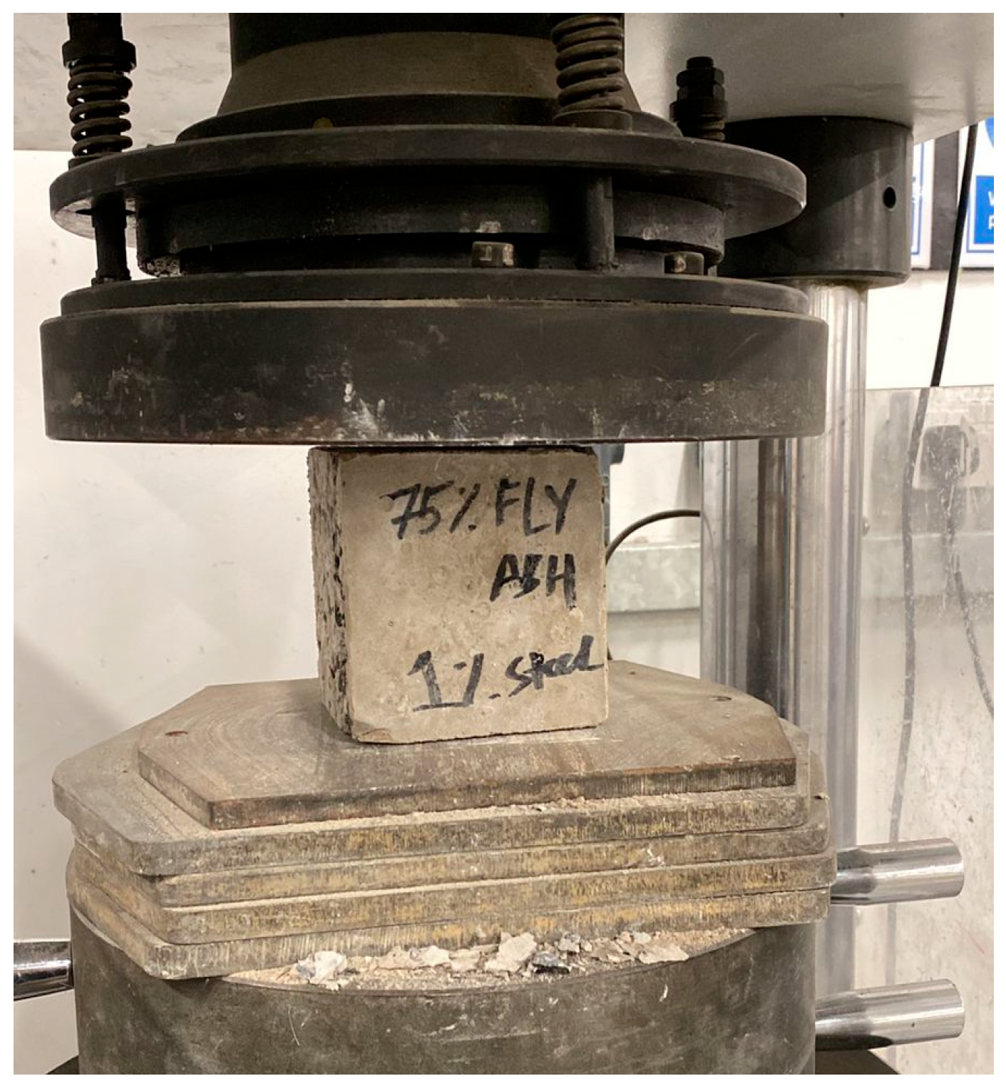
Figure 1. Compressive strength test setup.
Buildings 15 03533 g001
Figure 2. Flexural strength test setup.
Buildings 15 03533 g002
Figure 3. The effect of fiber content on compressive strength development: (a) Samples 75S25F; (b) Samples 50S50F; (c) Samples 25S75F.
Buildings 15 03533 g003
Figure 4. The effect of binder composition on compressive strength development: (a) Control Samples; (b) Samples Reinforced with 1% Steel Fiber; (c) Samples Reinforced with 2% Steel Fiber.
Buildings 15 03533 g004
Figure 5. Compressive strength development expressed as percentage gain at each curing interval.
Buildings 15 03533 g005
Figure 6. Failure modes of control cubes (a) 75S25FAC, (b) 50S50FAC, (c) 25S75FAC.
Buildings 15 03533 g006
Figure 7. Failure modes of 1% fiber reinforced cubes (a) 75S25FA1, (b) 50S50FA1, (c) 25S75FA1.
Buildings 15 03533 g007
Figure 8. Failure modes of 2% fiber reinforced cubes (a) 75S25FA2, (b) 50S50FA2, (c) 25S75FA2.
Buildings 15 03533 g008
Figure 9. Load–displacement responses for 28 days: (a) Samples 75S25F; (b) Samples 50S50F; (c) Samples 25S75F.
Buildings 15 03533 g009
Figure 10. Flexural Strength of prismatic beams at 28 days.
Buildings 15 03533 g010
Figure 11. Initial Stiffness of prismatic beams.
Buildings 15 03533 g011
Figure 12. Toughness of prismatic beams.
Buildings 15 03533 g012
Figure 13. Failure modes of control prismatic beams (a) 75S25FAC, (b) 50S50FAC, (c) 25S75FAC.
Buildings 15 03533 g013
Figure 14. Failure modes of fiber reinforced prismatic beams (a) 75S25FA, (b) 50S50FA, (c) 25S75FA.
Buildings 15 03533 g014
Table 1. Chemical components of slag, fly ash, and dune sand.
Oxide CompoundSlagFly AshDune Sand
Silicon dioxide, SiO2 (%)34.74864.9
Calcium oxide, CaO (%)423.314.1
Aluminum oxide, Al2O3 (%)14.423.13
Ferric oxide, Fe2O3 (%)0.812.50.7
Magnesium oxide, MgO (%)6.91.51.3
Loss on ignition, LOI (%)1.11.1-
Others (%)1.110.516
Values are in percentages.
Table 2. Physical properties of slag, fly ash, and dune sand.
Physical PropertiesSlagFly AshDune Sand
Specific gravity2.72.322.77
Uniformity coefficient2.869.11.47
Curvature coefficient0.711.451.09
Table 3. Physical properties of steel fibers.
Length (mm)Density (g/cm3)Elastic Modulus (GPa)Tensile Strength (MPa)Elongation
at Failure (%)
Melting
Temperature (°C)
137.882002.22.322.77
Table 4. Study Matrix.
GroupSample IDSlag (kg/m3)Fly Ash (kg/m3)Dune Sand (kg/m3)Coarse Aggregates (kg/m3)Sodium Silicate (kg/m3)Sodium Hydroxide (kg/m3)Super
Plasticizer (kg/m3)
Fiber Quantity (kg/m3)Fiber Length (mm)Fiber Geometry
WaterSH Flakes
A75S25FAC2257572512109938.9427.067.5013Straight
75S25FA12257572512109938.9427.067.5313Straight
75S25FA22257572512109938.9427.067.5613Straight
B50FA50SC15015072512109938.9427.067.5013Straight
50FA50S115015072512109938.9427.067.5313Straight
50FA50S215015072512109938.9427.067.5613Straight
C25S75FAC7522572512109938.9427.067.5013Straight
25S75FA17522572512109938.9427.067.5313Straight
25S75FA27522572512109938.9427.067.5613Straight
The quantity of fibers is taken as a percentage of the total binder content.
Table 5. Compressive strength results.
GroupSample IDAverage Compressive Strength (MPa) at 1 DayAverage Compressive Strength (MPa) at 7 DaysAverage Compressive Strength (MPa) at 28 Days
A75S25FAC15.1221.7830.23
75S25FA116.3423.7934.02
75S25FA220.2228.0038.15
B50S50FAC12.0419.9024.33
50S50FA115.1324.5728.32
50S50FA219.3427.5732.39
C25S75FAC9.5615.9319.90
25S75FA111.7317.5623.38
25S75FA214.4220.0125.62
Table 6. Peak load of prismatic beams at 28 days.
GroupSamplePeak Load (kN)Ultimate Displacement (mm)
A75S25FAC5.230.27
75S25FA17.252.18
75S25FA28.822.19
B50S50FAC4.310.24
50S50FA16.672.6
50S50FA27.952.59
C25S75FAC3.650.19
25S75FA15.122.81
25S75FA26.222.9
Table 7. Flexural strength values.
GroupSampleFlexural Strength (MPa)
A75S25FAC2.615
75S25FA13.625
75S25FA24.41
B50S50FAC2.155
50S50FA13.335
50S50FA23.975
C25S75FAC1.825
25S75FA12.56
25S75FA23.11
Table 8. Initial stiffness values.
GroupSampleInitial Stiffness (kN/mm)
A75S25FAC30.64
75S25FA163.73
75S25FA281.88
B50S50FAC28.524
50S50FA158.545
50S50FA274.11
C25S75FAC30.187
25S75FA140.989
25S75FA265.767
Table 9. Toughness values.
GroupSampleToughness (J)
A75S25FAC0.96
75S25FA19.45
75S25FA213.18
B50S50FAC0.64
50S50FA19.36
50S50FA212.869
C25S75FAC0.438
25S75FA14.91
25S75FA27.4
Disclaimer/Publisher’s Note: The statements, opinions and data contained in all publications are solely those of the individual author(s) and contributor(s) and not of MDPI and/or the editor(s). MDPI and/or the editor(s) disclaim responsibility for any injury to people or property resulting from any ideas, methods, instructions or products referred to in the content.