Article

Theoretical Method for Calculating the Second-Order Effect and Reinforcement of Reinforced Concrete Box Section Columns

1
Department of Standardization Engineering, Yibin University, Yibin 644000, China
2
Department of Faculty of Civil Engineering and Mechanics, Kunming University of Science and Technology, Kunming 650093, China
*
Author to whom correspondence should be addressed.
Buildings 2025, 15(19), 3528; https://doi.org/10.3390/buildings15193528
Submission received: 2 April 2025 / Revised: 2 May 2025 / Accepted: 7 May 2025 / Published: 1 October 2025
(This article belongs to the Special Issue Trends and Prospects in Civil Engineering Structures)

Abstract

Calculating the second-order effect and reinforcement of reinforced concrete box section columns has geometric nonlinearity and material nonlinearity. It requires integration and iterative solutions and is inconvenient in practical applications; moreover, China’s “Code for Design of Concrete Structures” (GB 50010-2010) uses the same formula as that for rectangular sections when calculating geometric nonlinearity. To find out a calculation method by hand that is specific to box-shaped sections and does not require iterative procedures, the theoretical derivation is adopted and divided into two gradations: (1) in terms of cross-section: using strain as the known variable to solve the internal force, thus solving the calculation problem of the bearing capacity of the cross-section; (2) in terms of members, the model column method can be used to solve the calculation problem of second-order effects of members. Finally, nomograms that can calculate the second-order effect and reinforcement of columns without iterative calculation are drawn, which contain five parameters, namely first-order bending moment, axial force, curvature, slenderness ratio, and the mechanical ratio of reinforcement. One of the nomograms corresponds to the cross-section resistance, and the other corresponds to the balance of internal resistance and external effect. Compared with the GB 50010-2010, the differences in the total bending moment and reinforcement ratio are within 10% and 20%, respectively. Compared with the numerical calculation results, the remaining examples are within 10% under normal load conditions.

1. Introduction

Columns are generally under the combined effect of axial force and bending moment. Calculating the bearing capacity and the reinforcement of a column has dual nonlinearity of geometry and material [1,2], and iterative calculation is required. Reinforced concrete box section (RCBS) members have excellent mechanical properties and are widely used in engineering construction. The formulas of I-shaped section capability calculation in GB 50010-2010 [3] can be used to calculate the reinforcement of RCBS approximately, which is necessary to judge the size of the eccentricity and is calculated based on the theory of a rectangular stress block of concrete.
Current research has developed analytical and numerical approaches to assess structural performance under complex loading. Studies [4,5] established methods for calculating the ultimate strength of concrete sections under biaxial bending, while another approach [6] streamlined surface integral computations for heterogeneous materials. Despite progress, analytical solutions for cross-sectional capacity under combined loads remain limited [7]. Second-order effects and load-path dependencies necessitate improved design models. Experimental evidence [8] from biaxial tests on reinforced concrete columns highlights discrepancies in capacity under bidirectional versus unidirectional loading. An iterative method [9] for slender column strength prediction requires computational refinement. Cyclic loading tests [10,11] further provide critical hysteretic data for validating load–displacement models, yet a gap persists in integrating these findings into efficient analytical frameworks. The methodologies employed for evaluating the ultimate bearing capacity of slender reinforced concrete (RC) columns are constrained by the limitations of experimental data and the scope of parameters involved [12]. Research focused on the deformation capacity of RC columns under specific loading conditions [13] remains inadequate for columns with large slenderness ratios, and the applicability of associated formulas is restricted. While theoretical/numerical procedures for analysing columns with arbitrarily shaped cross-sections [14] and computational methods for columns with arbitrarily polygonal cross-sections [15] are effective, they are limited to cross-sectional calculations and do not account for second-order effects in columns. The damage model for circular-section cantilever RC bridge piers [16] exhibits limited applicability. The analytical methods for interaction diagrams of ultimate bearing capacity in circular-section RC columns [17], design charts for biaxial bending in rectangular RC columns [18], computational methods for second-order effects in slender circular-section RC columns [19], research on the axial compression performance of high-strength steel-reinforced concrete short columns [20], and section resistance analysis of RC members based on Eurocode 2 [21] all fall short of achieving the objective of determining column reinforcement without iterative solutions. The analytical solution and calculation method by hand for the relationship between bearing capacity and deformation considering the second-order effect of box columns has not been found. Therefore, it is still necessary to directly calculate the second-order bending moment and reinforcement of the member by hand without iteration. In addition to providing a quick initial solution in the preliminary design, it can also serve as a verification tool for software calculation and numerical calculation.
In this paper, the “strain method” is used to solve the cross-sectional internal resistance [22]. A precise algorithm for calculating the ultimate curvature of a cross-section has been proposed. Assuming that the deflection curve of the member is a quadratic parabola, a simplified formula for calculating the ultimate curvature is proposed, and a nomogram for calculating the second-order bending moment of the member is drawn. Nomograms enable direct hand calculations of the total bending moment and reinforcement requirements for box-section columns based solely on applied loads, eliminating the need for moment amplification factors derived from rectangular-section assumptions or iterative computational procedures.

2. Calculation of Cross-Sectional Internal Force

2.1. Basic Assumptions

To obtain the analytical calculation formula for the cross-sectional bearing capacity (normal relative force and bending moment), the following assumptions were adopted: (1) cross-sections remain plane after deformation, (2) the tensile strength of concrete is ignored, (3) there is a good bond between concrete and reinforcing steels, (4) the shear deformation is neglected, (5) the shrinkage and creep of concrete are neglected, (6) the influence of rotational capacity on ultimate resistance is neglected.

2.2. Constitutive Relationship

The constitutive relationship of concrete and reinforcing steels in GB 50010-2010 [3] is shown in Figure 1.
The mathematical expressions are:
σ s d = f y d ε s d < ε y d E s ε s d ε s d ε y d f y d ε s d > ε y d
σ c d = f c d ( 1 ( 1 ε c d 2.0 ) 2 ) 0 > ε c d > 2.0 f c d 2.0 ε c d 3.3
In Equation (1), ε s d and σ s d are strain and stress of steel, respectively. ε y d and f y d are design yield strength and yield strain of the steel, respectively. E s is the elastic modulus of elasticity of the reinforcing steels. The stress and strain are positive in tension and negative in compression in this study.
In Equation (2), ε c d , σ c d and f c d are the concrete strain and stress, and the design compressive strength of concrete, respectively. The strain of 10‰ is the ultimate tensile strain of steel reinforcement specified in GB 50010-2010, while the strain of 3.3‰ is the ultimate compressive strain of concrete.
The different stress–strain relationships of materials will affect the formula for cross-sectional bearing capacity and affect the final calculation nomogram, meaning that one material constitutive relationship corresponds to one nomogram. Nomograms in this article apply to the concretes of C50 and below.

2.3. Cross-Sectional Strain Region and Geometric Relationship of the Section

The strain method indicates that if the strain of the cross-section is known, the corresponding stress of the cross-section can be calculated by Equations (1) and (2). Therefore, if the ultimate strain of the section is known, the ultimate bearing capacity of the cross-section can be accurately calculated. The ultimate strain of a cross-section means that the concrete or reinforcing steels at some position in the cross-section reach the ultimate strain regulated in GB 50010-2010, which can be divided into 5 regions, as shown in Figure 2.
The characteristics depicted in Figure 2 are outlined as follows:
(1)
As shown in the box-shaped cross-section in Figure 2a, the black circular dots represent the steel reinforcement bars, and the gray areas indicate the concrete.
(2)
Region 1: The neutral axis descends from an infinite position above the cross-section to the upper edge thereof. The stress state undergoes a transformation from uniformly distributed tension to tension with minor eccentricity. At the left boundary of the region, the strain distribution manifests as uniform tension, wherein the strain values of all reinforcing steels attain a specific magnitude ε s 2 = 10 .
(3)
Region 2, 3, and 4: A portion of the cross-section experiences compressive stresses, with the neutral axis migrating into the cross-section and progressively descending from the upper edge to the lower edge. The load scenarios transition sequentially from tension with minor eccentricity to tension with substantial eccentricity, pure bending, compression with substantial eccentricity, and compression with a minor eccentricity, successively.
(4)
Region 5: The right boundary line of Region 4 concurrently serves as the boundary line for Region 5. It rotates counterclockwise around point A to the vertical position (point A can be calculated from the geometric relationship between the upper and lower edge strains of the right boundary line of Region 4). The entire cross-section is subjected to compressive stresses; the neutral axis moves from the bottom of the cross-section to an infinite position below it. The load cases transition from compression with a minor eccentricity to uniform compression.
(5)
Strain Continuity and Load Transition: The strain changes continuously from Region 1 to Region 5, and the corresponding load cases also gradually transition.
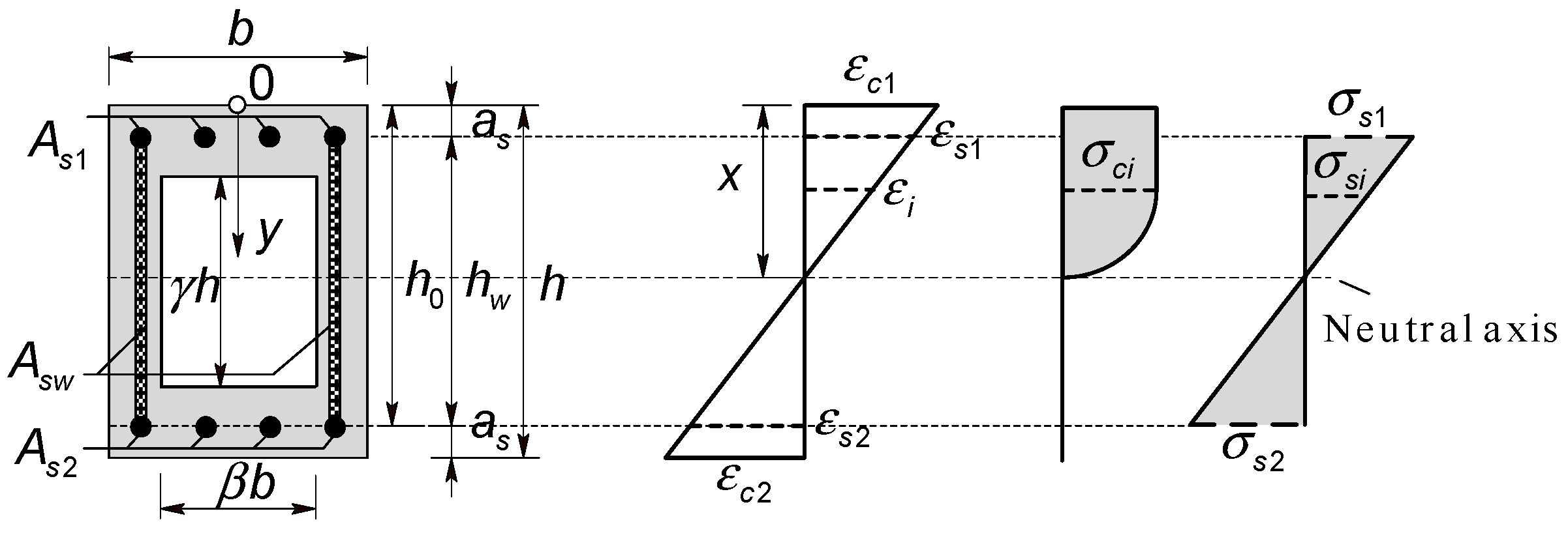
According to the strain and geometric relationship of the cross-section, Figure 3 can be drawn, and Figure 3 can be used as one of the bases for deriving formulas for calculating the internal force of the cross-section. As shown in Figure 3, under the bending moment generated by uniaxial loading, the neutral axis of the cross-section is horizontal.
Due to the different constitutive relationship between reinforcing steels and concrete, when calculating the internal force of the cross-section, it should be divided into two parts: concrete and reinforcing steels.
Knowing the strain of the cross-section edges ( ε c 1 and ε c 2 ), the strain at any depth of the cross-section ( ε i ) can be calculated, thus the stress of concrete at any depth of the cross-section ( σ c i ) and internal force of concrete of the cross-section can be calculated.
To obtain a convenient calculation, the depth of the concrete compression zone can be obtained from the geometric relationship (as shown in Figure 3):
x = ε c 1 ε c 1 ε c 2 h
The strain at any depth of the cross-section can be computed:
ε i = x y x ε c 1

2.4. Internal Force Calculation of Concrete

Substituting Equation (4) into Equation (2), the stress σ c i of the concrete at any depth of the cross-section can be calculated, and the axial force N c and the bending moment M c of the concrete can be computed by integrating the stress σ c i along the cross-section depth y :
N c = 0 x σ c i b ( y ) d y M c = 0 x σ c i b ( y ) ( y h 2 ) d y
Equation (5) is related to cross-section parameters, where the cross-section width varies with the cross-section depth y: b ( y ) = b     y h ( 1 γ ) / 2 ; y h ( 1 + γ ) / 2 β b   h ( 1 γ ) / 2 < y < h ( 1 + γ ) / 2 . It can become more versatile by turning Equation (5) into a dimensionless one so the normal relative force n c and dimensionless bending moment m c of concrete can be calculated:
n c = N c b h f c m c = M c b h 2 f c

2.5. The Internal Force Calculation of Reinforcing Steels

According to the characteristics of the distribution of reinforcing steels, the reinforcing steels can be divided into two parts to calculate the internal force: the upper and lower edges, and the webs.
(1)
The upper and lower edges: ignoring the influence of the size of the reinforcing steel, the strain at the centre of the reinforcing steels ( ε s 1 and ε s 2 ) can be calculated as follows based on Figure 3:
ε s 1 = x a s x ε c 1
ε s 2 = x ( h a s ) x ε c 1
Substituting Equations (7) and (8) into Equation (1), the stresses σ s 1 and σ s 2 of the reinforcing steels can be obtained. Then, the axial force N s f and the bending moment M s f of the reinforcing steels can be calculated:
N s f = A s 1 σ s 1 + A s 2 σ s 2 M s f = ( A s 1 σ s 1 A s 2 σ s 2 ) ( a s h 2 )
(2)
The webs: to simplify the calculation, the scattered reinforcing steels are simplified into reinforcing steel strips with the same area as the original reinforcing steels, as shown in Figure 3. The per unit length area of the reinforcing steel strips can be written as follow:
A ¯ s w = A s w h 2 a s
Substituting Formula (4) into Formula (1) to calculate the stress of the reinforcing steels at any depth in the cross-section ( σ s i ), the axial force N s w and the bending moment M s w of the reinforcing steels can be computed by integration:
N s w = a s h a s σ s i A ¯ s w d y M s w = a s h a s σ s i A ¯ s w ( y h 2 ) d y
Total force N s and bending moment M s of reinforcing steels:
N s = N s f + N s w M s = M s f + M s w
By making Equation (12) dimensionless, the normal relative force n s and the dimensionless bending moment m s of all the reinforcing steels can be calculated:
n s = N s b h f c m s = M s b h 2 f c

2.6. Calculation of the Full Cross-Section Resistance

The dimensionless internal force of the full cross-section is the sum of the internal forces of concrete and reinforcing steels:
n = n c ( ε c 1 , ε c 2 ) + n s ( ε c 1 , ε c 2 , ω ) m = m c ( ε c 1 , ε c 2 ) + m s ( ε c 1 , ε c 2 , ω )
In Equation (14), the ω represents the total mechanical ratio of reinforcement of the cross-section, and it can be written as follows:
ω = ω s 1 + ω s 2 + ω s w = A s 1 f y d + A s 2 f y d + A s w f y d b h f c d
As shown in Figure 3, the factors in the examples and diagrams in this article are taken as the following: γ = β = 0.6 , a s = 0.1 h , A s w = 2 A s 1 = 2 A s 2 .

2.7. Relationship Between the Mechanical Ratio of Reinforcement and Dimensionless Ultimate Eccentricity

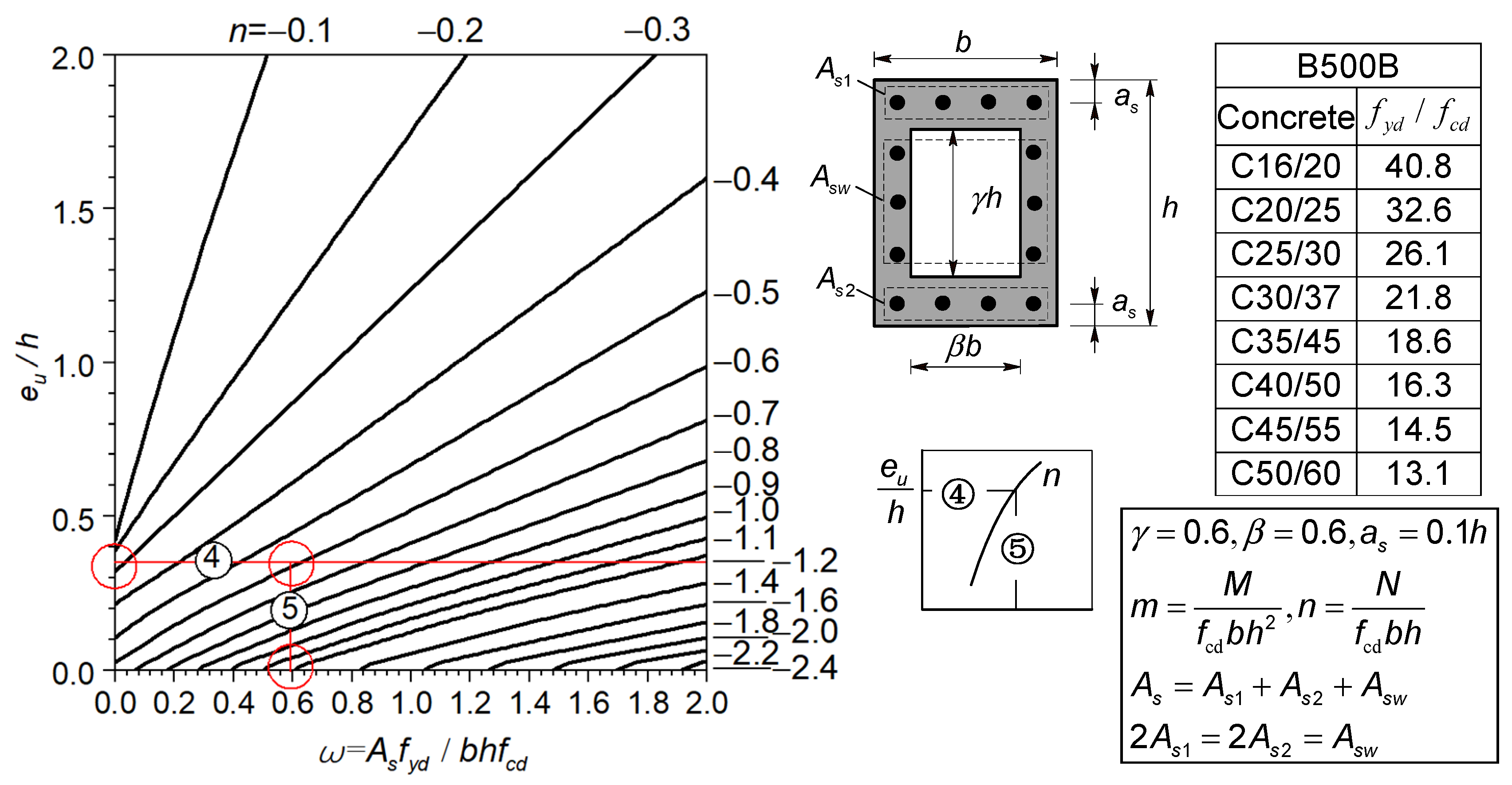
The two equations in Equation (14) are both nonlinear equations, and the independent variables connecting the two equations are ε c 1 , ε c 2 , and ω . Calculating the dimensionless ultimate bending moment m u when n is known is performed using the first equation of Equation (14) to find the ultimate strains ( ε c 1 and ε c 2 ) that satisfy the characteristics shown in Figure 2. Substituting the strains ( ε c 1 and ε c 2 ) into the second equation of Equation (14), the m u can be found. The calculation results are plotted in Figure 4, with the relative dimensionless ultimate eccentricity ( e u / h = m u / n ) as the abscissa.
In Figure 4, it can be intuitively deduced that e u / h has a positive linear relationship with the cross-sectional mechanical ratio of reinforcement ω . When ω is the same, the smaller n is, the larger the allowable e u / h is. When the e u / h is the same and n increases, the required ω increases. Figure 4 reflects the relationship between the bearing capacity ( n and m u ) of the cross-section and ω , which is part of the nomograms for column reinforcement calculation.

2.8. Relationship Between Normal Relative Force and Dimensionless Ultimate Curvature

The crux of coupling material nonlinearity with geometric nonlinearity lies in characterizing the linkage between cross-sectional internal force distribution and the resultant member deflection, where the latter is inherently governed by the geometric distortions of individual cross-sections. The deformation of a cross-section can be expressed by the cross-section curvature Φ . According to the geometric relationship of cross-sections, as shown in Figure 3, the cross-section curvature Φ  can be calculated by Equation (16) when the deformation is small.
Φ = ε c 2 ε c 1 h
Dimensionless curvature can be expressed by Equation (17):
ϕ = Φ h = ε c 2 ε c 1
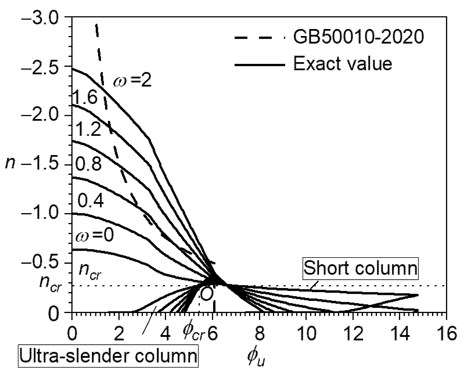
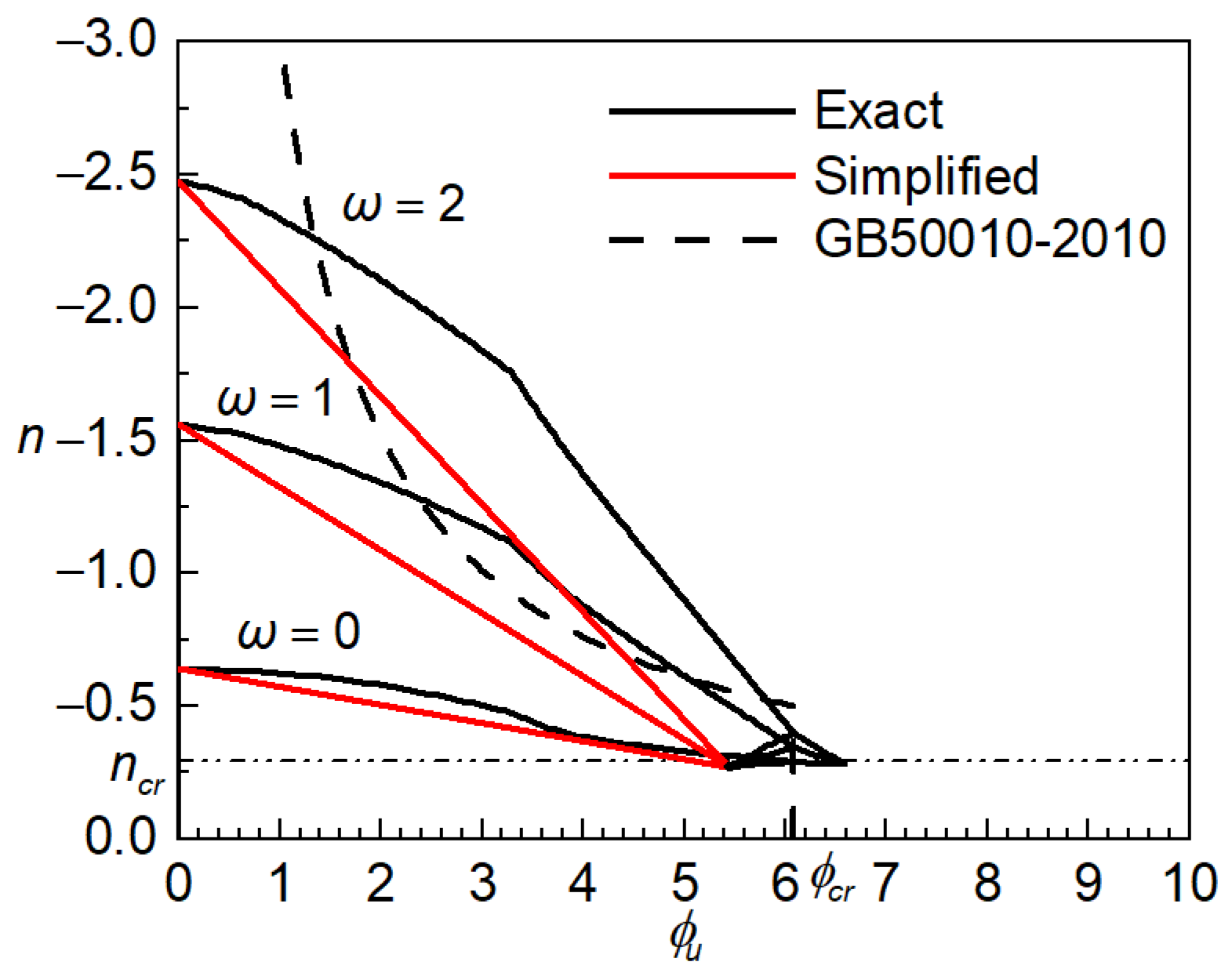
Given different values of ω , we substitute the strain ( ε c 1 and ε c 2 ) included in the ultimate strain state as shown in Figure 2 into Equation (17) to calculate dimensionless ultimate curvature ϕ u , then substitute the strain ( ε c 1 and ε c 2 ) into the first equation of Equation (14) to obtain n so that the curves of short columns in Figure 5 can be drawn. For slender columns, the yield strain of reinforcing steels is adopted as the ultimate strain for tension-side reinforcement. The subsequent calculation procedure remains identical to the preceding analysis, and the resultant load-deformation responses correspond to the curves for slender columns depicted in Figure 5. The relationship between n and ϕ u in GB 50010-2010 is calculated by Equation (18) and is shown in Figure 5 too.
ϕ u = 0.5 n ( ε y d 1.25 ε c u 1 a s / h )
where ε c u = 3.3 is the concrete ultimate compressive strain.
The intersection point O in Figure 5 indicates that the reinforcing steels on the upper and lower edges of the cross-section have become yielding at the same time ( ε s 1 = ε y d ,   ε s 2 = ε y d ), and that n is not related to ω at this time. The current curvature is called the critical curvature ϕ c r :
ϕ c r = 2 ε y d / ( 1 2 a s / h )
The values of ε c 1 and ε c 2 can be determined by the cross-sectional geometric relationship in Figure 3, and the corresponding normal relative force n c r = 0.27 can be obtained by substituting ε c 1 and ε c 2 into the first equation of Equation (14).

3. Simplified Calculations of the Second-Order Effect of Columns (In Terms of Members)

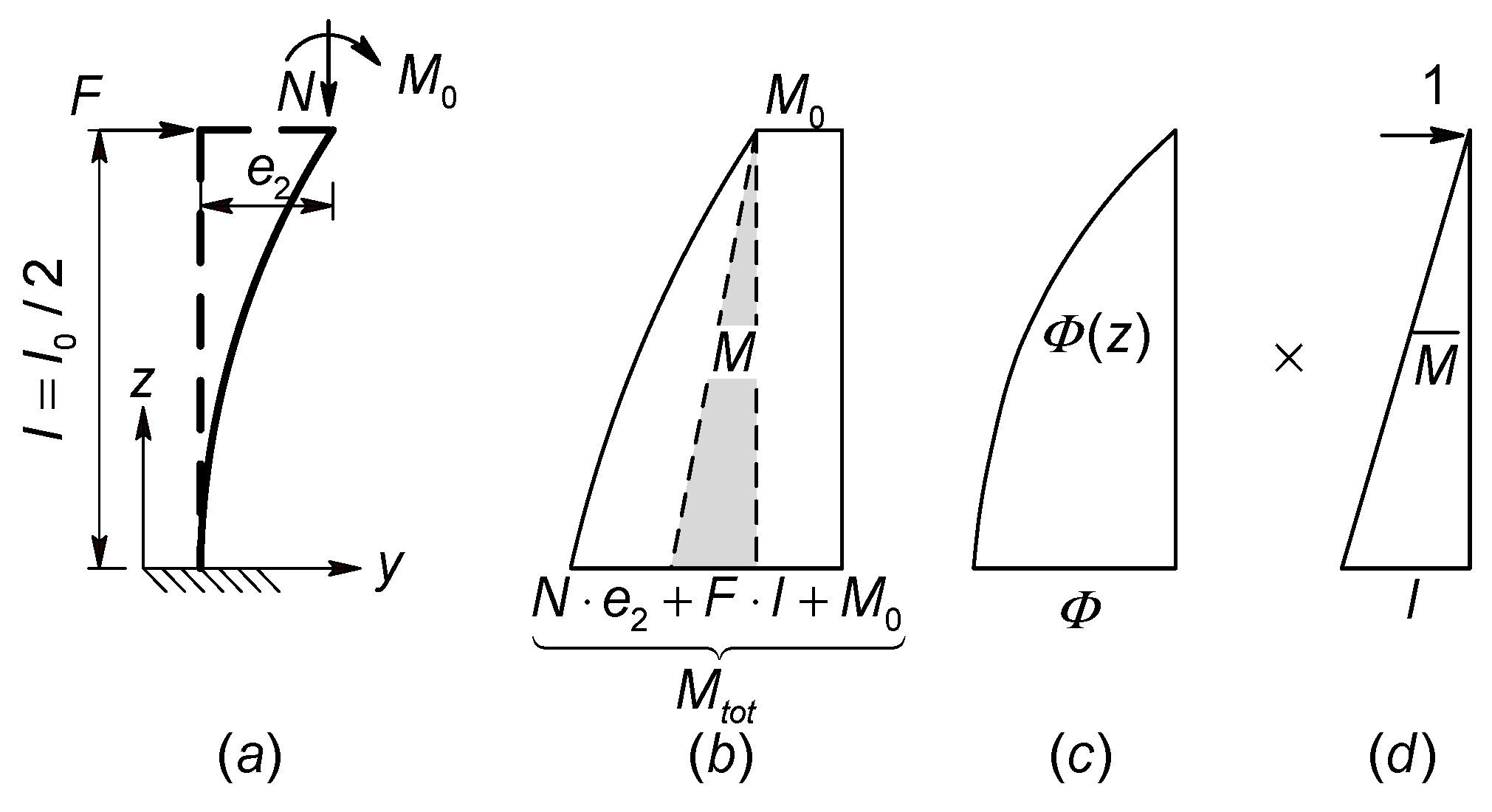
The second-order bending moment effects in columns are analysed using the model column method, which establishes a simplified mechanical model to capture the geometric nonlinearity induced by axial–flexural coupling in slender structural members. Corresponding to the load applied on the section, the model column is also subjected to uniaxial loading. An axial force N , a lateral force F , and a bending moment M 0 are applied to the cantilever column, where the effective length of the cantilever column is l 0 = 2 l and e 2 is the second-order eccentricity, as shown in Figure 6a. The maximum bending moment of the column is at the fixed end, and the fixed end cross-section will reach the ultimate strength first. The fixed-end bending moment M t o t caused by the load is the sum of the first-order bending moment ( M 1 = F l + M 0 ) and the second-order bending moment ( M 2 = N e 2 ) , as shown in Figure 6b.
Owing to the mutual coupling of geometric and material nonlinearities, accurate evaluation of the column’s second-order bending moment necessitates an iterative segmented analysis. During each iteration, the stiffness ( E I ) of individual column segments is dynamically updated based on the current state of deformation and stress. The total deflection curve, accounting for second-order effects, is obtained only after convergence of the iterative process. However, since the reinforcement layout within the cross-section remains undetermined, the initial stiffness ( E I ) values required for iterative analysis cannot be directly computed. We can only start with the deflection of the column and make two simplifications during the calculation: (1) Assume that the curvature ( Φ ( z ) = M t o t ( z ) E I ( z ) ) of the column is distributed as a quadratic parabola [3,23,24]. (2) Assume that the curvature of the fixed end cross-section is Φ , as shown in Figure 6c.
The end restraint conditions of frame columns are reflected in the effective length of the columns [25]. The effective length ( l 0 = 2 l ) of the cantilever column is known, a transverse unit force is applied to the free end of the cantilever column, and the bending moment distribution along the length of the column is shown in Figure 6d. By using the moment area method, e 2 can be obtained:
e 2 = Φ ( Z ) M ¯ d Z 2 3 l Φ 5 8 l = 5 48 Φ l 0 2
Thus, the second-order total bending moment M t o t can be calculated:
M t o t = M 1 + N e 2 = F l + M 0 + 5 48 N Φ l 0 2
The dimensionless total eccentricity e t o t h is:
e t o t h = M t o t N h = M 1 N h + e 2 h = e 1 h First   order + 5 48 l 0 h 2 Second   order ϕ
The dimensionless total bending moment m t o t can then be calculated:
m t o t = n e t o t h = n e 1 h First   order + 5 48 n l 0 h 2 Second   order ϕ
It can be seen from Equations (22) and (23) that the key to solving the dimensionless total eccentricity and bending moment of the column is ϕ , which corresponds to the bearing capacity of the cross-section.
Because any column can be isolated from the structure and become a single independent column based on the effective length [24,25], Equations (22) and (23) can have universal application, which can be used to calculate the second-order deflection and second-order bending moment caused by the P Δ and P δ effects of any column in the structure, because the magnitude of P Δ and P δ effects are both reflected in the different effective lengths.

4. Equilibrium of Internal Resistance and External Effect

4.1. The Equilibrium of the Second-Order Bending Moment of the Member and the Internal Force of the Cross-Section

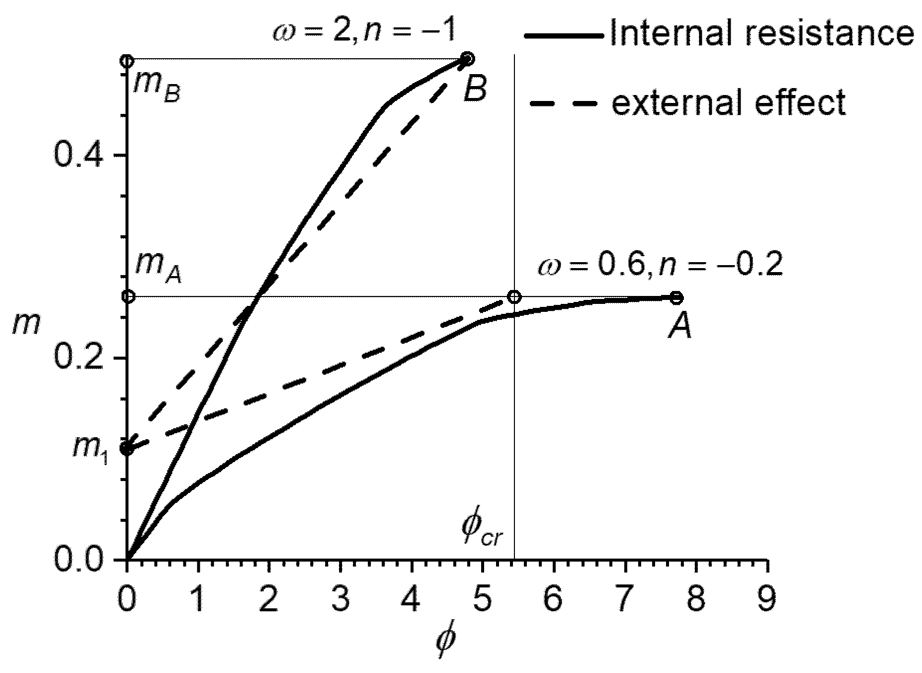
Taking a short column as an example where the values of n and ω are known, ϕ u can be calculated with the steps presented in Section 2.8: letting the value of ϕ increase from 0 to ϕ u , the strains ( ε c 1 and ε c 2 ) corresponding to each ϕ can be calculated by the first equation of Equation (14), then substituting the strains ( ε c 1 and ε c 2 ) into the second equation of Equation (14) can be used to calculate m . Thereby the curves of the relationship between m and ϕ can be drawn in Figure 7, which represents the internal resistance. From Equation (23), the curves of the relationship between m t o t and ϕ in Figure 7 can be drawn, which represents the external effect.
In Figure 7, when the absolute value of n is small, such as n = 0.2 , ϕ u is greater than ϕ c r . After ϕ exceeds ϕ c r , the rate at which the slope of the thick solid line decreases accelerates, indicating the bending stiffness of the cross-section decreases sharply. In this case, let ϕ = ϕ c r in Equation (23) to calculate m t o t . When the absolute value of n is large, such as n = 1 , ϕ u is less than ϕ c r . At this time, let ϕ = ϕ u in Equation (23) to calculate m t o t . Overall, m t o t = m u is always taken as the equilibrium point in any situation, such as points A and B.

4.2. Simplification of Dimensionless Ultimate Curvature

The equilibrium point of internal resistance and external effect is related to ϕ u , and it can be found in Figure 5 that ϕ u varies nonlinearly with n . To simplify calculation, let ϕ u change linearly with n , as shown in Figure 8.
Simplified ϕ u can be calculated by Equation (24):
ϕ u = n u n n u n c r ϕ c r         n n c r ϕ c r                                       n > n c r
where n u is the maximum normal relative force that the cross-section can sustain without bending moment. Since the limit strain value for axial compression of the section specified in GB50010-2010 is −2.0‰, it means that at this time, the strain of any position in the cross-section is −2.0‰, hence the value of n u can be calculated by the following formulas:
n u = ω 1     ε y 2 2 ω ε y 1     ε y > 2  
With the simplified calculation expression of ϕ u shown in Equation (24), the m t o t at the fixed end of the column can be calculated by substituting the ϕ = ϕ u that was calculated using Equation (24) into Equation (23).

4.3. Error Analysis of Calculating Column Bearing Capacity with Simplified Ultimate Curvature

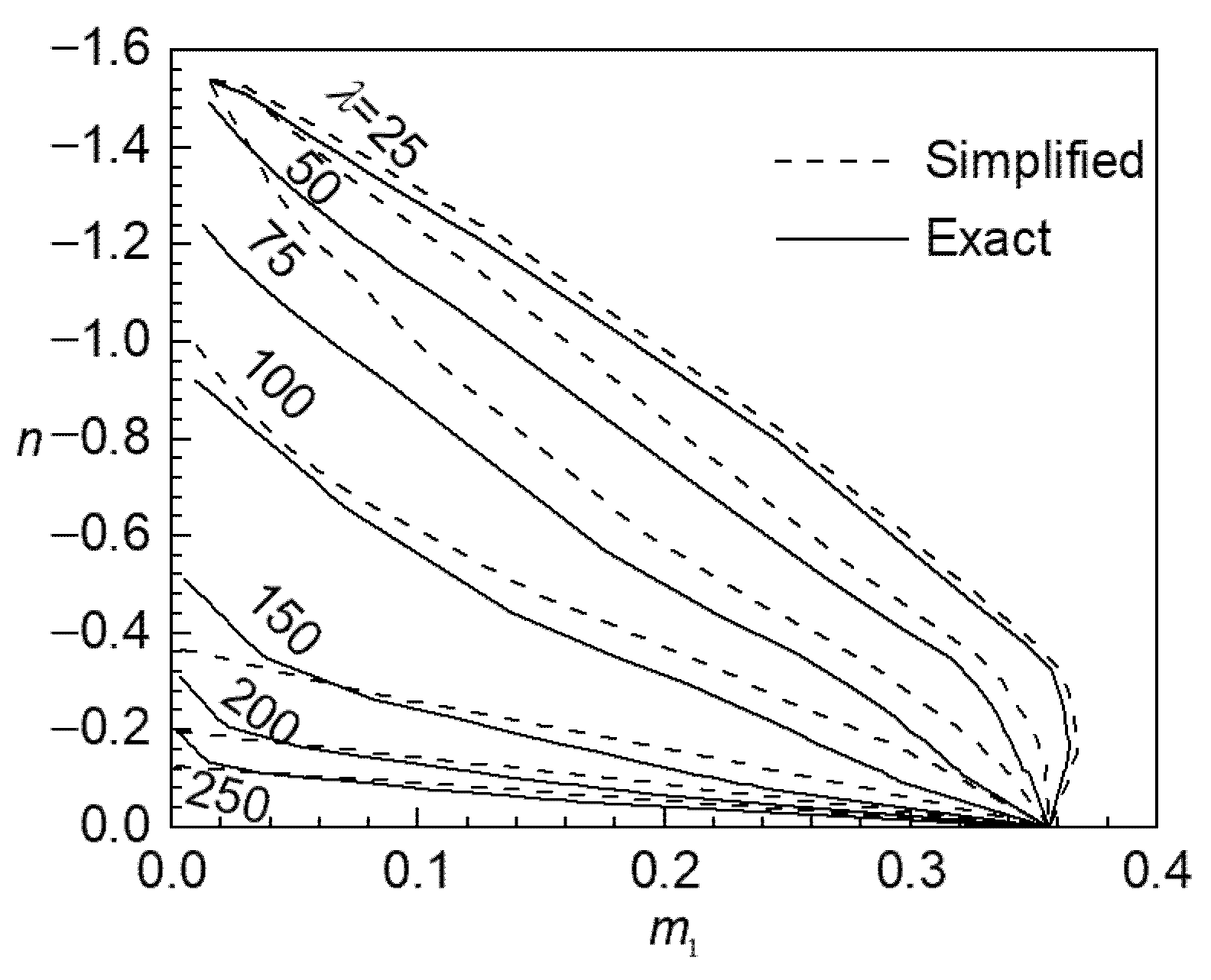
Letting ω = 1 , n u can be obtained by Equation (25): let the first-order eccentricity e 1 increase from 0 to 3 h in steps of 0.01 whilst the slenderness ratio λ of the column is fixed. The simplified value of ϕ u calculated by Equation (24) is substituted into Equation (23) to calculate the m t o t of the column. The exact calculation results of m t o t are obtained through the conjugate beam method based on the analytical relationship of m ϕ [25]. The convergence criterion is based on the deformation convergence of the member. Specifically, during program calculation, convergence is indicated when the ratio of the deflection difference of the corresponding column between two consecutive iterations to the total deflection is less than 1‰. Finally, the corresponding n and first-order bending moment m 1 = n e 1 when m t o t = m u can be found by the dichotomy. The curves of the relationship between n and m 1 corresponding to the two values of ϕ u in Figure 9 can be drawn.
It is shown in Figure 9 that λ 25 . The difference between the two methods is very small, and the second-order effect of the component is small; when λ > 25 , there is little difference between the two methods, and when the eccentricity approaches 0, the maximum difference in bearing capacity can reach 30%. However, there are almost no such load cases, and the remaining examples are relatively close, being within 10%. In actual engineering, when the accuracy requirements are not strict, the simplified ultimate curvature can be used for calculation.

5. Nomograms for Calculating the Mechanical Ratio of Reinforcement and Second Effect of Columns

5.1. Drawing Method of the Nomogram

The calculation problems of resistance and second-order effect of columns are solved below, respectively.
(1)
The slope of the external effect line in Figure 7 can be obtained by Equation (23):
k c = 5 48 n ( l 0 h ) 2
Add a coordinate axis to the right side of the nomogram so that the slope k c can be directly derived from the known n l 0 h . If we let ϕ x = 0.006 be the abscissa of the coordinate axis, then the ordinate of the coordinate axis is:
y = 5 48 ϕ x n ( l 0 h ) 2
Equation (23) shows that the external effect is related to ϕ , e 1 , n and l 0 / h of the column. When e 1 , n , and l 0 / h are known, the slope k c of the straight line representing the external effect is calculated by Equation (26), and the value of ϕ corresponding to the final deflection of the column depends on the internal resistance of the cross-section.
(2)
The part of internal resistance: each value of n is selected from −0.1 to −2.4 and is fixed, then we let ω increase from 0 to 2 with the steps of 0.01, thus m u of the cross-section can be calculated with calculation methods presented in Section 2.6, and the simplified dimensionless ultimate curvature ϕ u can be calculated by Equation (24). Curves can be drawn with ϕ u as the abscissa and m u as the ordinate, as shown in Figure 10.
The equilibrium point means that m t o t of the column is equal to m u of the cross-section. Because the dimensionless ultimate eccentricity e u / h of the cross-section corresponds to ω , a simple conversion ( e u / h = m u / n ) is finished, and we substitute e u / h into Figure 4 to calculate the mechanical ratio of reinforcement ω of the column.

5.2. The Specific Steps of Using the Nomograms

The value of m t o t can be found by checking Figure 10 according to the known values of n , the first-order eccentricity e 1 / h , and the slenderness ratio l 0 / h , which is equal to the m u of the cross-section. Then, checking Figure 4 from known n and e u / h = m u / n , ω of the column is obtained. The detailed method is as follows:
(1)
Compute l 0 / h , m 1 , n and e 1 / h according to the known load and component size.
(2)
Draw line ① by known n l 0 h ;
(3)
Draw line ② by making the parallel line of line ① through m 1 ;
(4)
Draw a horizontal line ③ through the intersection point of line ② and the known n curve to find the value of m t o t ;
(5)
Calculate e u / h using the following equations: m u = m t o t , e u / h = m u / n ;
(6)
Draw horizontal line ④ by known e u / h ;
(7)
Draw a vertical line ⑤ through the intersection point of line ④ and the known n curve to the abscissa to find ω .

5.3. Comparison of Nomograms and GB 50010-2010

Some specific examples are analysed to verify the feasibility of the nomograms. It is known that for a box-shaped cross-section-reinforced concrete column, the thickness of the longitudinal reinforcing steels protection layer is a s = a s = 0.1 h , HRB500 grade reinforcing steels is adopted ( f y = 435   N / mm 2 ), the elastic modulus is E s = 2 × 10 5   N / mm 2 , and the yield strain is ε y = 2.175 . The grade of concrete is C 30 ( f c = 14.3   N / mm 2 ), and the cross-section height and width are h = 600   mm and b = 400   mm , respectively. The effective length of the column is l 0 = 12   m   ( l 0 / h = 20 ) . Axial compression force is N = 2000   kN , and the first-order bending moment is M 1 = 240   kN m .
(1)
Calculate using the nomograms
First-order dimensionless eccentricity is:
e 1 h = M 1 N h = 240 × 10 6   N mm 2000 × 10 3 N × 600 mm = 0.20
Normal relative force is:
n = N b h f c = 2000 × 10 3   N 400   mm × 600   mm × 14.3 N / mm 2 = 0.58
Dimensionless first-order bending moment is:
m 1 = n e 1 h = 0.12
In Figure 10, line ① can be drawn by connecting the origin and n l 0 h = 15.27 , line ② can be drawn by making a parallel line of line ① through m 1 = 0.12 , line ③ can be drawn by making a horizontal line at the intersection of line ② and the n = 0.58 curve (interpolation method), and then m t o t = m u = 0.20 and e u / h = m u / n = 0.35 can be computed. In Figure 4, line ④ can be drawn using the known e u / h , line ⑤ can be drawn by drawing a perpendicular line at the intersection of line ④ and the n = 0.58 curve (interpolation method), then ω = 0 . 59 can be found, and the area of all the reinforcing steels is calculated using the following:
A s = ω b h f c f y = 0.59 × 400   mm × 600   mm × 14.3   N / mm 2 435   N / mm 2   =   4684   mm 2
The total moment is:
M t o t = m t o t b h 2 f c = 0.203 × 400   mm × ( 600   mm ) 2 × 14.3   N / mm 2 = 418   kN m
(2)
Calculate using GB 50010-2010
To calculate the design value of the second-order bending moment of the column in accordance with GB 50010-2010, the adjustment coefficient of the eccentricity of the column is:
C m = 0.7 + 0.3 M 1 M 2 = 1.0
The curvature correction factor is:
ζ c = 0.5 b h f c N = 0.86
The bending moment increase factor is:
η n s = 1 + ζ c h 0 1300 ( M N + e a ) ( l 0 h ) 2 = 1 + 0.86 × 540   mm 1300 × ( 240 2000 × 10 3 + 20 )   mm 20 2 = 2.01
The design value of the total bending moment can be calculated as follows:
M t o t = C m η n s M 1 = 485   kN m
The box-shaped cross-section reinforcement can be approximately solved by the calculation formulas of the I-shaped cross-section in GB 50010-2010. The formulas applicable to the concrete strength grade not exceeding C50 and after the conversion according to the variables indicated in Figure 3 are as follows:
N f c d ξ β b h 0 + ( b β b ) ( 1 γ ) h 2 + f y d A s 1 σ s A s 2 + N s w N e f c ξ ( 1 0.5 ξ ) β b h 0 2 + ( b β b ) ( 1 γ ) h 2 ( h 0 ( 1 γ ) h 4 ) + f y d A s 1 ( h 0 a s ) + M s w
where N s w and M s w are:
N s w = ( 1 + ξ 0.8 0.4 h w / h 0 ) f y d A s w M s w = 0.5 ( ξ 0.8 0.4 h w / h 0 ) 2 f y d A s w h w
where ξ is the compression zone depth ratio of the cross-section, γ = β = 0.6 , a s = 0.1 h , ω s w = ω s f , and A s w = 2 A s 1 = 2 A s 2 . If only ξ and the total reinforcement area ( A s = A s 1 + A s 2 + A s w ) is unknown, then A s can be obtained by solving Equations (28) and (29): A s   =   4251   mm 2
(3)
Comparison of the two methods
According to the above calculation results, the ratio of reinforcement calculated by GB 50010-2010 and nomograms is 0.91, and the ratio of the total bending moment is 1.16. To compare the calculation results of the two methods under different load cases, the cross-section parameters are unchanged, and each load is different. The results of the total moment and the reinforcement area calculated by the two methods are shown in Table 1.
(1)
The dimensionless ultimate curvature ϕ u calculated by GB 50010-2010 is only related to the normal relative force. When n n c r , the simplified ultimate curvature values calculated by GB 50010-2010 and the nomograms are both fixed values, as shown in Figure 8. At this time, the values of m t o t calculated by the two methods are very close. In examples 1 and 2, the difference is within 6%. As the m 1 increases, the difference in m t o t decreases, while the difference in A s increases.
(2)
In Example 3, the difference in m t o t and A s calculated by the two methods is 5% and −12%, respectively. Although the ϕ u and m t o t calculated by GB 50010-2010 are larger than that calculated by nomograms, the A s calculated by GB 50010-2010 is smaller than those calculated by nomograms. It shows that the difference between the two methods is reflected in the value of ϕ u and m t o t of the column, and also in the internal force calculation of the cross-section.
(3)
Only when the n and m 1 are both small, as in Example 1, is A s as calculated by the nomograms more economical, and, in other cases, it is safer.

6. Conclusions

In the realm of cross-sectional analysis, the strain method, which utilizes the comprehensive constitutive relationship of concrete as stipulated in GB 50010-2010, exhibits exceptional accuracy in computing cross-sectional bearing capacity without the necessity for iteration. It not only accurately determines internal forces under various stress conditions but also clearly defines the relationship between cross-sectional curvature (deformation) and internal force. At the member level, the model column method accounts for both material and geometric nonlinearities when assessing the second-order effect of columns. A novel approach has been introduced specifically for calculating the second-order effect of box-cross-section columns, offering enhanced accuracy compared to the increase coefficient method for rectangular cross-sections. Iterative problems are transformed into dimensionless nomograms, incorporating five influencing factors: first-order bending moment, axial force, curvature, slenderness ratio, and reinforcement mechanical ratio. This method enables the calculation of the column’s second-order bending moment, providing a manual approach for second-order elastoplastic box column design and verification.
Compared to GB 50010-2010, discrepancies in total bending moment and reinforcement ratio are within 10% and 20%, respectively, indicating relative safety. When compared to numerical calculations, the maximum difference in bearing capacity approaches 30% as eccentricity approaches zero; however, such loading cases are rare, with most examples differing by less than 10%.
Despite the study’s advancements, several limitations exist. Firstly, the influence of shear deformation is ignored, potentially introducing inaccuracies in scenarios with significant shear deformation. Secondly, shrinkage and creep effects are not considered, which may limit the methods’ applicability in practical engineering due to their substantial impact on long-term behaviour. Future research should focus on addressing these limitations.

Author Contributions

Conceptualization, D.Z.; methodology, D.Z. and L.L.; validation, L.L. and X.G.; formal analysis, D.Z.; data curation, software, and writing—original draft preparation, L.L.; writing—review and editing, X.G.; Funding, G.C. All authors have read and agreed to the published version of the manuscript.

Funding

The financial supports from the National Natural Science Foundation of China (Grant No. 51668027) and Yibin University Pre-research Project (Grant No. 2021YY09) are gratefully acknowledged.

Data Availability Statement

All calculated data have been plotted into graphs/charts. Should you require specific data points, please contact the author via email.

Acknowledgments

The research described in this paper was financially supported by the National Natural Science Foundation of China and Yibin University Pre-research Project.

Conflicts of Interest

The authors declare no conflicts of interest. The funders had no role in the design of the study; in the collection, analyses, or interpretation of data; in the writing of the manuscript; or in the decision to publish the results.

List of Abbreviations

A s Total reinforcement area
A s 1 Total area of upper reinforcement
A s 2 Total area of lower reinforcement
A s w The total area of the web reinforcing steel strips
A ¯ s w The per unit length area of the web reinforcing steel strips
a s Distance between the longitudinal reinforcement force point and the near edge of the section
b The width of the cross-section
E s Elastic modulus of reinforcement
E I Flexural rigidity of section
e 1 First-order eccentric distance
e 2 Second-order eccentric distance
e tot Total eccentric distance
e u Ultimate eccentric distance
F Lateral concentrated force
f c d Design compressive strength of concrete
f y d Design tensile (compressive) strength of reinforcement
h The height of the cross-section
h w The height of the web reinforcing steel strips
h 0 Effective height of the cross-section
k c Simplified slope of the external action curve
l Length of column
l 0 Effective length of column
M Total bending moment distributed along the length of the member
M 1 First-order bending moment
M 2 Second-order bending moment
M c Bending moment of concrete
M s Bending moment of reinforcing steel
M s f Bending moment of reinforcing steel at the upper and lower edges
M s w Bending moment of the web reinforcing steel strips
M t o t Maximum bending moment distributed along the length of the member
M u Ultimate bending moment of the cross-section
m Dimensionless bending moment ( = M / ( f c d b h ) )
m 1 Dimensionless first-order bending moment
m 2 Dimensionless second-order bending moment
m c Dimensionless bending moment of concrete
m s Dimensionless bending moment of reinforcing steel
m t o t Dimensionless maximum bending moment distributed along the length of the member
m u Dimensionless ultimate bending moment
N Axial force
N c Axial force of concrete
N s Axial force of reinforcing steel
N s f Axial force of reinforcing steel at the upper and lower edges
N s w Axial force of the web reinforcing steel strips
N u Ultimate axial force
n Dimensionless axial force/axial tension ratio/axial compression ratio ( = N / ( f c d b h ) )
n c Dimensionless resultant force of concrete
n c r Critical dimensionless axial force at strain of ε s 1 = f y d , ε s 2 = f y d
n s The dimensionless resultant force of reinforcement in reinforced concrete section
y Dimensionless deflection coordinate
z Dimensionless length coordinate
γ Geometric parameters of the cross-section: The height ratio between the hollow part and the exterior of the box-shaped cross-section
β Geometric parameters of the cross-section: The width ratio between the hollow part and the exterior of the box-shaped cross-section
ε Strain
ε c d Design compressive strain of concrete
ε c i Concrete strain at any location of cross-section
ε c 1 Upper edge strain of concrete section
ε c 2 Lower edge strain of concrete section
ε i Strain at any location of cross section
ε s d Design compressive strain of reinforcing steel
ε s i Reinforcing steel strain at any location of cross-section
ε s 1 Upper reinforcement strain of reinforced concrete section
ε s 2 Lower reinforcement strain of reinforced concrete section
ε y d Design yield strain of reinforcing steel
λ Slenderness ratio ( = 12 l 0 / h )
σ Stress
σ c d Stress of concrete
σ c 1 Stress of upper concrete in reinforced concrete section
σ c 2 Stress of lower concrete in reinforced concrete section
σ s d Stress of reinforcing steel
σ s 1 Stress of upper reinforcing steel in reinforced concrete section
σ s 2 Stress of lower reinforcing steel in reinforced concrete section
Φ Curvature
Φ Dimensionless curvature ( = Φ h )
Φ c r Critical dimensionless yield curvature at strain of ε s 1 = - ε y d , ε s 2 = ε y d
Φ u Dimensionless ultimate curvature
Φ y d Dimensionless yield curvature
ω Mechanical reinforcement ratio of total reinforcing steel ( = ( A s f y d ) / ( f c d b h ) )
ω s 1 Mechanical reinforcement ratio of upper reinforcing steel ( = ( A s 1 f y d ) / ( f c d b h ) )
ω s 2 Mechanical reinforcement ratio of lower reinforcing steel ( = ( A s 2 f y d ) / ( f c d b h ) )
ω s w Mechanical reinforcement ratio of web reinforcing steel strips ( = ( A s w f y d ) / ( f c d b h ) )

References

  1. Xu, J.; Gong, J. Nonlinear Second-Order Effect of Non-Sway Columns. ACI Struct. J. 2013, 110, 755–765. [Google Scholar]
  2. Babazadeh, A.; Burgueno, R.; Silva, P.F. P-δ Effects on the Plastic Region of RC Bridge Columns: Closed-Form Solution. J. Struct. Eng. 2016, 142, 04016116. [Google Scholar] [CrossRef]
  3. GB 50010-2010; Code for Design of Concrete Structures. China Architecture and Building Press: Beijing, China, 2010.
  4. Dundar, C.; Sahin, B. Arbitrarily shaped reinforced concrete members subject to biaxial bending and axial load. Comput. Struct. 1993, 49, 643–662. [Google Scholar] [CrossRef]
  5. Dündar, C. Concrete box sections under biaxial bending and axial load. Struct. Eng. 1990, 116, 860–865. [Google Scholar] [CrossRef]
  6. Pisani, M.A. A numerical method to analyse compact cross-sections. Comput. Struct. 1996, 59, 1063–1072. [Google Scholar] [CrossRef]
  7. Sousa, J.B.M.; Muniz, C.F.D.G. Analytical integration of cross section properties for numerical analysis of reinforced concrete, steel and composite frames. Eng. Struct. 2007, 29, 618–625. [Google Scholar] [CrossRef]
  8. Qiu, F.; Li, W.; Pan, P.; Qian, J. Experimental tests on reinforced concrete columns under biaxial quasi-static loading. Eng. Struct. 2002, 24, 419–428. [Google Scholar] [CrossRef]
  9. Hong, H.P. Strength of Slender Reinforced Concrete Columns under Biaxial Bending. J. Struct. Eng. 2001, 127, 758–762. [Google Scholar] [CrossRef]
  10. Chang, S.-Y. Experimental Studies of Reinforced Concrete Bridge Columns under Axial Load Plus Biaxial Bending. J. Struct. Eng. 2010, 136, 12–25. [Google Scholar] [CrossRef]
  11. Di Ludovico, M.; Verderame, G.M.; Prota, A.; Manfredi, G.; Cosenza, E. Experimental Behavior of Nonconforming RC Columns with Plain Bars under Constant Axial Load and Biaxial Bending. J. Struct. Eng. 2013, 139, 897–914. [Google Scholar] [CrossRef]
  12. Kwak, H.-G.; Kwak, J.-H. An improved design formula for a biaxially loaded slender RC column. Eng. Struct. 2010, 32, 226–237. [Google Scholar] [CrossRef]
  13. Barrera, A.C.; Bonet, J.L.; Romero, M.L.; Fernández, M. Ductility of slender reinforced concrete columns under monotonic flexure and constant axial load. Eng. Struct. 2012, 40, 398–412. [Google Scholar] [CrossRef]
  14. Dundar, C.; Tokgoz, S.; Tanrikulu, A.K.; Baran, T. Behaviour of reinforced and concrete-encased composite columns subjected to biaxial bending and axial load. Build. Environ. 2008, 43, 1109–1120. [Google Scholar] [CrossRef]
  15. Guan, Z.; Zhang, J.; Li, J. A Robust Computational Method for Ultimate Strength Analysis of Arbitrary Reinforced Concrete and Composite Sections Subjected to Axial Force and Biaxial Bending. Adv. Struct. Eng. 2014, 17, 83–96. [Google Scholar] [CrossRef]
  16. Perdomo, C.; Monteiro, R. Simplified damage models for circular section reinforced concrete bridge columns. Eng. Struct. 2020, 217, 110794. [Google Scholar] [CrossRef]
  17. Laora, R.D.; Galasso, C.; Mylonakis, G.; Cosenza, E. A simple method for N-M interaction diagrams of circular reinforced concrete cross sections. Struct. Concr. 2020, 21, 48–55. [Google Scholar] [CrossRef]
  18. Papanikolaou, V.K.; Sextos, A.G. Design charts for rectangular R/C columns under biaxial bending: A historical review toward a Eurocode-2 compliant update. Eng. Struct. 2016, 115, 196–206. [Google Scholar] [CrossRef]
  19. Klempka, K.; Jędrzejczak, M. Design of Slender Reinforced Concrete Columns of Annular Cross-Section According to the Nominal Curvature Method and the Exact Method. In Proceedings of the 2017 Baltic Geodetic Congress (BGC Geomatics), Gdansk, Poland, 22–25 June 2017; pp. 143–147. [Google Scholar]
  20. Wang, J.; Wang, X.; Duan, Y.; Su, Y.; Yi, X. The Investigation on Mechanical Performances of High-Strength Steel Reinforced Concrete Composite Short Columns under Axial Load. Materials 2022, 15, 329. [Google Scholar] [CrossRef]
  21. Lechman, M. Cross-Sectional Analysis of the Resistance of RC Members Subjected to Bending with/without Axial Force. Materials 2022, 15, 1957. [Google Scholar] [CrossRef]
  22. Zhou, D.H.; Wang, Q.F.; Fan, J.; Gao, Q.X.; Wang, H.Y. A new method for the calculation of reinforcement of concrete: General dimensionless designing diagram. Eng. Mech. 2010, 27, 162–172. [Google Scholar]
  23. Wei, W.; Zhu, A.; Liu, Y.; Bai, S. Design methods of reinforced concrete frame column considering P-δ effect. J. Build. Struct. 2006, 27, 64–71. [Google Scholar]
  24. Wei, W.; Qin, H.P.; Yu, D.J. Design method of multiple-story column considering second-order effect in frame structure. J. Build. Struct. 2018, 39, 135–142. [Google Scholar]
  25. Timoshenko, S.; Goodier, J.N. Theory of Elasticity; Xu, Z.L.; Wang, Y.Z., Translators; People’s Education Press: China, Beijing, 1964. [Google Scholar]
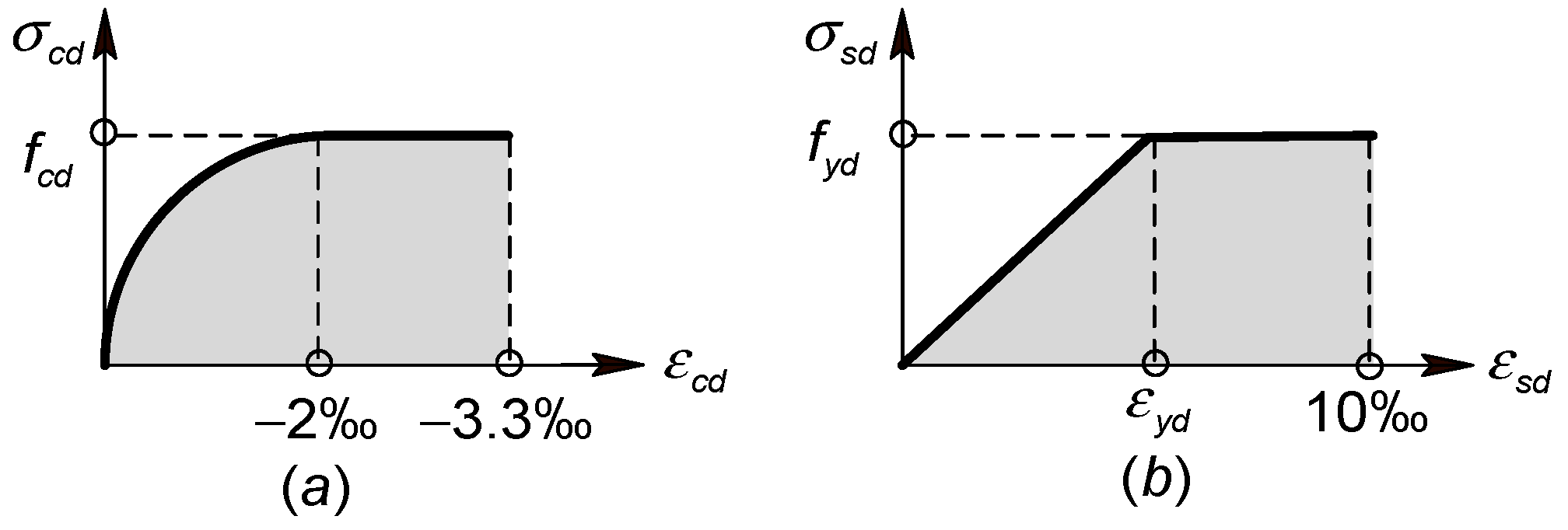
Figure 1. Constitutive relationship (a) concrete (b) reinforcing steel.
Buildings 15 03528 g001
Figure 2. The schematic diagram and ultimate strain distribution of the cross-section: (a) Schematic diagram of cross-section, (b) The ultimate strain distribution of the of the cross-section.
Buildings 15 03528 g002
Figure 3. Cross-sectional calculation diagram (geometric relationship of stress and strain).
Buildings 15 03528 g003
Figure 4. Curves of the relationship between dimensionless ultimate eccentricity ( e u / h ) and mechanical ratio of reinforcement ( ω ) when normal relative force ( n ) is constant.
Buildings 15 03528 g004
Figure 5. Curves of relationship between normal relative force ( n ) and dimensionless ultimate curvature ( ϕ u ).
Buildings 15 03528 g005
Figure 6. Column calculation diagram: (a) The deflection and loading of column, (b) The distribution of total bending moment along the length of the column, (c) The curvature distribution along the length of the column, (d) The bending moment generated by a fictitious unit force.
Buildings 15 03528 g006
Figure 7. Curves of the relationship between dimensionless total moment ( m t o t ) and dimensionless curvature ( ϕ ).
Buildings 15 03528 g007
Figure 8. Simplified relationship of dimensionless ultimate curvature ( ϕ u ) and normal relative force ( n ).
Buildings 15 03528 g008
Figure 9. Ultimate bearing capacity (normal relative force ( n ) and first-order bending moment ( m 1 )) curves.
Buildings 15 03528 g009
Figure 10. Total bending moment ( m t o t ) calculation nomogram.
Buildings 15 03528 g010
Table 1. The table of the different examples.
Examples n m 1 l h m t o t m ( 1 ) m ( 2 ) A s (mm)2 A s ( 1 ) A s ( 2 ) ϕ u (Code) ϕ u (Nomogram)
(1) Code(2) Nomogram(1) Code(2) Nomogram
1−0.20.1200.1520.1451.05168416031.056.305.44
2−0.20.5200.5550.5451.0211,99212,7590.946.305.44
3−0.60.3200.4300.4081.05935310,6020.885.254.32
4−10.1200.2040.1911.07616273100.843.152.19
5−10.3200.4250.4460.9511,41814,3440.803.153.49
6−20.1200.1830.1890.9713,36915,2860.871.581.07
Disclaimer/Publisher’s Note: The statements, opinions and data contained in all publications are solely those of the individual author(s) and contributor(s) and not of MDPI and/or the editor(s). MDPI and/or the editor(s) disclaim responsibility for any injury to people or property resulting from any ideas, methods, instructions or products referred to in the content.