1. Introduction
Controlled demolition is a specialized engineering process where a structure is systematically dismantled using pre-planned techniques to ensure safety, efficiency, and minimal environmental impact. Unlike uncontrolled collapses, controlled demolition employs precise calculations, sequencing, and methods such as explosive charges, mechanical dismantling with machinery or hybrid approaches to direct the structure’s failure in a controlled and predictable manner [
1]. It is commonly used for the safe removal of aging buildings, infrastructure, and hazardous structures, with a focus on environmental considerations and efficient debris management [
2].
As structures age, they may reach the end of their functional lifespan, incur irreparable damage, or require demolition for other reasons. The rapid pace of urbanization has increased the demand for controlled demolition of buildings that have either exceeded their service life or are no longer fit for use. In such cases, the implementation of “controlled-safe demolition” becomes crucial to ensure safety and mitigate potential risks [
1,
2,
3].
This study provides a pioneering overview of the current state-of-the-art in demolition engineering, focusing on the critical interplay between methodological selection, advanced analytical techniques, and risk mitigation strategies. It aims to offer a comprehensive perspective that sheds light on future research directions and lays the foundation for upcoming studies in the field.
Research in controlled demolition is vital for driving innovation and improving safety measures. However, significant gaps remain in the field, such as simulating practical and accurate demolition behavior and developing predictive models. These predictive models are crucial for controlled demolitions, particularly in urban settings, as they not only help prevent unintended damage to surrounding buildings but also allow potential collapse scenarios and debris trajectories to be anticipated and managed effectively, thereby directly enhancing safety and reliability.
Furthermore, addressing the environmental impacts of demolition practices and developing more sustainable methods are pressing concerns. Research on material recovery and waste management after demolition could greatly contribute to sustainability and resource management efforts. In particular, the health risks associated with dust generated during demolition, and the hazards posed by materials such as asbestos, require careful management; safe disposal sites must be ensured, and materials should be professionally separated to enable potential reuse. Previous studies have examined demolition and construction waste from multiple perspectives. For instance, Thomsen et al. [
4] explored the conceptual distinction between deconstruction, demolition, and destruction, emphasizing the need for a transdisciplinary approach to understand their societal implications. Yuan and Shen [
5] reviewed the development of research on construction and demolition (C&D) waste management, highlighting emerging trends, dominant methodologies, and the increasing contribution from both developed and developing economies. Similarly, Menegaki and Damigos [
6] investigated the challenges of C&D waste management, identifying barriers, drivers, and systemic interrelations through a concept map framework. Mália et al. [
7] focused on the development of quantitative indicators for C&D waste, providing estimates across different construction and demolition sectors within the EU context. In parallel, Wu et al. [
8] conducted an analytical review to quantify C&D waste, offering insights into measurement techniques and the reliability of existing data sources. Despite these studies, the challenges remain in effectively managing environmental impacts, optimizing material recovery, and ensuring safe and sustainable waste handling throughout demolition projects.
To date, only a limited number of numerical simulations employed to study structural collapse caused by blast-generated waves. While some studies have focused on the demolition of structures [
1,
2,
3,
4,
5,
6,
7,
8,
9], a significant body of work has concentrated on the inverse problem—enhancing the robustness of structures to prevent collapse [
10,
11,
12,
13]. Both scaled prototype models and full-scale tests play a crucial role in understanding structural behavior. While the former is more commonly utilized due to practical constraints, full-scale tests, which require substantial funding and effort, are also present in the literature and provide significant contributions to the field of structural engineering [
14].
More recently, as structural monitoring gains increasing importance [
15,
16,
17,
18,
19], innovations have integrated real-world displacement data into controlled demolition research [
1,
2]. This approach uses stationary cameras and drones positioned outside the critical collapse zone, extracting displacement data from video footage segmented into frames using specialized software. By incorporating the time-dependent displacement measurements into numerical simulations, rather than relying solely on visual comparisons, numerical simulations can be validated more accurately, ensuring that predicted structural responses closely reflect actual collapse dynamics and thereby enhancing safety and efficiency in demolition practices. As the number of such studies increases, this approach is expected to facilitate improved calibration of models and support future predictive analyses. In this scenario, Controlled demolition and its associated research areas are gaining increased attention, with much still to be explored by emerging scholars. Eventually, the landscape of demolition will evolve with the integration of high-fidelity models and AI (artificial intelligence), enhancing precision, safety, and ultimately leading to more efficient project completions. These tools can allow multiple scenarios to be simulated more rapidly and extensively, providing probabilistic insights that enable more informed pre-assessments and, over time, higher prediction accuracy, thereby enhancing safety and efficiency in controlled demolition. Therefore, the primary objective of this study is to provide a comprehensive framework from various perspectives, helping researchers gain a clear and thorough understanding of the current state of the field and identifying potential avenues for future exploration.
Each section begins with a written explanation, followed by a chart that summarizes the processes discussed.
Section 2 examines the methods of demolition techniques in terms of efficiency, safety, and practicality, with the processes summarized in both a chart and a table.
Section 3 focuses on the general framework and decision-making process for selecting demolition methods, visualized in a chart.
Section 4 investigates the effects of blasting sequence and delay timing through two 23-story building scenarios, highlighting differences between floor-to-floor and axis-by-axis delays on structural collapse, debris spread, and toppling control, with the results illustrated in charts and figures.
Section 5 highlights the key procedures of controlled demolition, including planning, risk assessment, and execution, with the relevant processes summarized in a chart. Finally,
Section 6 explores advanced analysis methods and future prospects for controlled demolition, incorporating high-fidelity models; Artificial Intelligence (AI), Machine Learning (ML) and Deep Learning (DL) tools, with the processes outlined and summarized in a chart.
2. Methods of Demolition Techniques: Efficiency, Safety, and Practicality
Demolition is a complex process that requires careful planning and execution to ensure safety, efficiency, and minimal environmental impact. Depending on a structure’s characteristics, surrounding conditions, and project requirements, different demolition techniques can be employed. While some methods prioritize speed and effectiveness, others focus on control and precision to mitigate risks in urban environments.
The choice of demolition method depends on multiple factors, including structural composition, the surrounding environment, project objectives, and safety protocols. For instance, while explosive demolition is often preferred for large-scale projects due to its efficiency, techniques such as mechanical demolition and top-down demolition are commonly utilized in urban settings. Each method has distinct advantages and limitations, requiring a careful evaluation of project-specific constraints. This section provides an in-depth analysis of these techniques, emphasizing their operational principles and suitable use cases. One of the most widely used techniques is ‘explosive demolition’, which relies on carefully placed charges to induce structural implosion. This method is particularly effective for high-rise buildings, bridges, wind turbines and large industrial facilities where rapid demolition is necessary. However, despite its efficiency, explosive demolition demands rigorous engineering analysis and expert oversight to prevent unintended structural damage to nearby buildings (
Figure 1).
For structures where explosives are not a viable option, ‘Mechanical demolition’ serves as an alternative. ‘Mechanical demolition’ relies on heavy machinery such as high-reach excavators, hydraulic breakers, and crushers to dismantle structures. This method is particularly suitable for mid-rise buildings and industrial structures. Utilizing high-reach excavators equipped with hydraulic breakers and crushers, the method allows for the systematic disassembly of buildings (
Figure 2).
A more traditional yet still relevant approach is ‘wrecking ball demolition’, which employs a heavy steel ball swung from a crane to break concrete and masonry. Although less commonly used in modern projects due to its lack of precision, this method remains an option for structures (
Figure 2). It is generally considered less precise than mechanical or modern explosive demolition techniques. The success of wrecking ball demolition depends on the skill of the operator and the structural integrity of the building. However, its primary drawback is the significant and slow dust generation and the potential for uncontrolled debris dispersion. The potential for uncontrolled debris makes wrecking ball demolition less desirable, especially in densely populated areas.
When dealing with structures that require both force and precision to demolish, pulling and pushing demolition techniques appears as an emerging demolition method. The pulling and pushing method, namely ‘Mechanized Tension Extraction (METE)’, involves steel cables or ropes attached to heavy machinery, gradually bringing the structure down. Conversely, the ‘pushing (only) method’ utilizes bulldozers or hydraulic rams to exert directional force, facilitating controlled collapses. This approach is particularly useful for minarets and some silos, where precision is essential but full mechanization is not required (
Figure 2).
In contrast to these forceful methods, ‘top-down demolition’ offers a more gradual and slower approach to demolish buildings. Beginning from the uppermost floors and progressing downward, this technique is conducted with the aid of mini-excavators and scaffolding (
Figure 2). Its primary advantage lies in minimizing the risks associated with uncontrolled debris fall, making it a preferred option for demolition projects in high-density urban settings. However, this method also presents significant safety concerns, particularly due to the presence of workers and machinery at elevated levels. If the upper structure experiences unexpected instability or sudden partial collapse, the risk of fatal accidents increases. Therefore, precise structural assessments, continuous monitoring, and well-planned load redistribution are critical to ensuring worker safety throughout the process. The [Flow chart-1] below provides an overview of main demolition methods, categorizing them based on their techniques and applications (
Figure 2).
Beyond these conventional methods, specialized techniques such as ‘thermic demolition’, ‘chemical demolition’, and ‘selective deconstruction’ offer targeted solutions for unique challenges. Thermic demolition involves cutting through thick steel and reinforced concrete using high-temperature tools, while chemical demolition relies on expanding agents that penetrate cracks and gradually break apart concrete. Meanwhile, selective deconstruction emphasizes careful dismantling for renovation and historic preservation, promoting sustainability by salvaging reusable materials. Ultimately, the choice of demolition method depends on project-specific constraints and objectives. The integration of advanced engineering analyses with innovative demolition strategies has the potential to enhance structural safety while reducing environmental and social impacts. As demolition technologies continue to evolve, more efficient, precise, and environmentally responsible approaches are shaping the future of urban redevelopment and infrastructure renewal.
In addition to
Figure 2, here
Table 1 summarizes different demolition methods based on their time efficiency, technological advancement, and predictability. This table also highlights their common applications and key limitations, providing a comparative overview of each method (
Table 1).
Each method’s practicality is further contextualized by its common applications and inherent limitations (
Table 1). Faster and technologically advanced methods, such as explosive and chemical demolition, offer high predictability but require precise engineering and specialized expertise. The high speed and precision of explosive demolition make it suitable for large-scale structures such as high-rise buildings, bridges, and industrial facilities, though it requires detailed engineering analysis. Mechanical and pulling-pushing demolitions offer moderate efficiency and control, making them viable for various building types, including mid-rise structures and wind turbines, but with concerns related to vibration and collapse direction control. Wrecking ball demolition is more suited for older structures with low material quality, easy collapsibility, and no surrounding buildings, though it lacks precision and poses risks of uncontrolled debris. Methods such as selective deconstruction prioritize debris safety and controlled dismantling, but they are significantly slower and labor-intensive. By outlining these factors,
Table 1 facilitates a structured evaluation of demolition techniques, aiding in the selection of the most appropriate approach based on project constraints and objectives.
3. General Framework and Decision-Making Process
The controlled demolition process begins with an assessment of the existing structure to determine its suitability for continued use or replacement, focusing on its dynamic structural performance. A dynamic structural performance analysis is conducted to evaluate the integrity and seismic resilience of the building. This involves a detailed performance analysis to determine whether the structure meets safety and functional standards [
20,
21].
If the structure is deemed adequate, it can continue to be used without requiring retrofitting or demolition. However, if the structure is found to be inadequate, further steps are taken. A cost–benefit analysis is performed to evaluate whether retrofitting the building is a viable solution. If retrofitting is deemed feasible and cost-effective, necessary strengthening measures are applied to improve the building’s structural performance. On the other hand, if retrofitting is either not practical or too costly, the decision is made to proceed with demolition.
The next stage involves determining the reason for demolition, which may include constructing a new structure or creating space for new roadways or other urban planning purposes. Once this decision is finalized, the planning phase for demolition begins, focusing on ensuring safety and efficiency throughout the process. A critical aspect of this phase is selecting the most appropriate demolition method, which depends primarily on factors such as building height and proximity to adjacent structures. In this study, a specific distinction is introduced for seven-story buildings.
It is important to note that the maximum reach height of demolition machinery varies depending on the model and manufacturer. However, standard lattice boom demolition machines available in the market typically have a reach capacity ranging from 20 to 30 m. For a structure approximately seven stories high (around 21 m), a demolition machine with a reach of 25–30 m is generally sufficient. Consequently, a distinction has been made for buildings of this height. Additionally, for safe and effective mechanical demolition, other critical parameters—such as the machine’s weight, operating angle, and breaker power—must also be considered to optimize performance and mitigate potential risks.
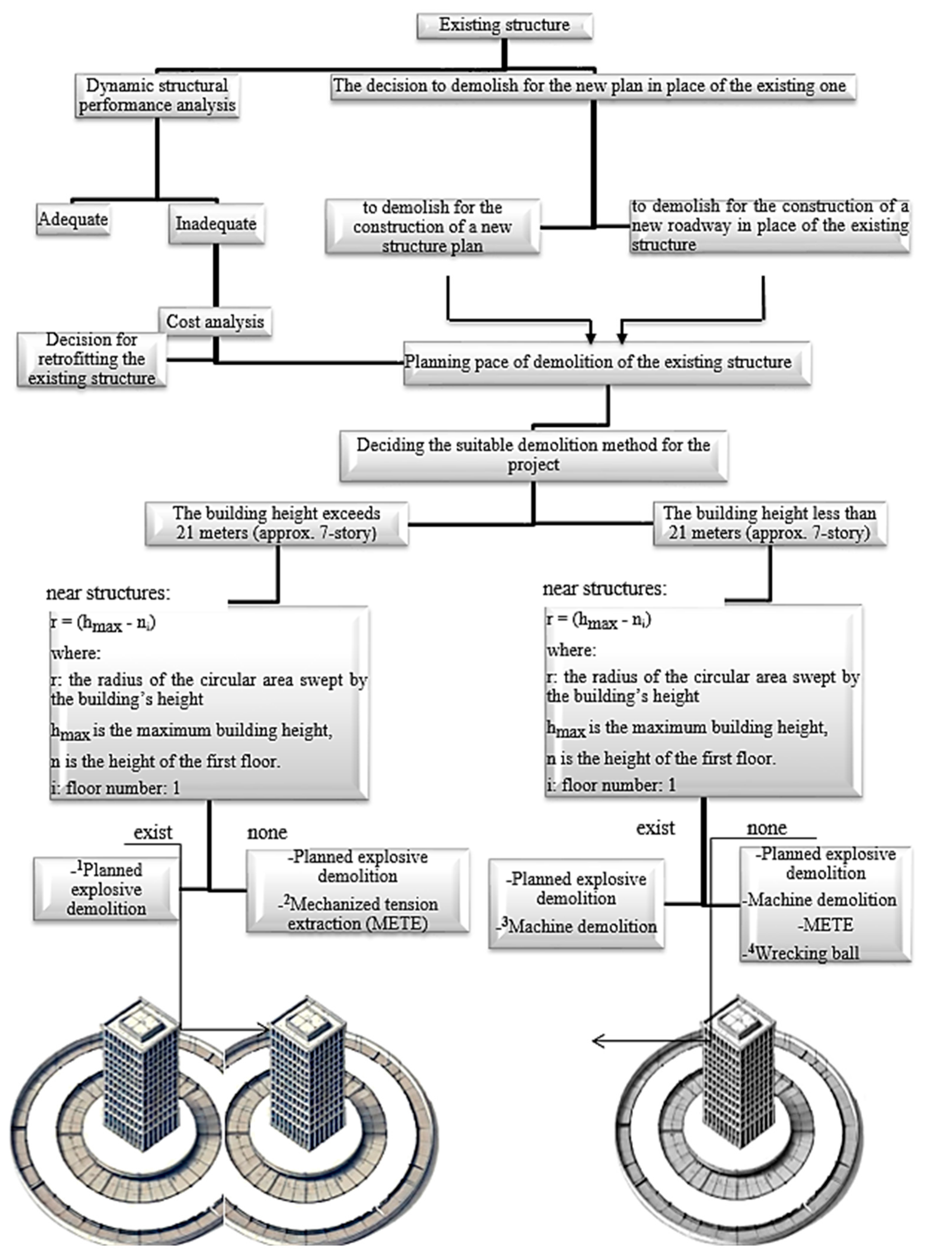
For buildings exceeding 21 m (approximately seven stories), the demolition radius is determined using Equation (1):
where “r” is the radius of the circular area swept by the building’s height, “hmax” is the maximum height of the building, and ni is the height of the (first) floor. All units in Equation (1) are in meters (SI). In some cases, where the first floor or multiple lower floors may collapse vertically at the beginning of the demolition process, the effective overturning length is reduced, thereby allowing for a potential reduction in the swept area depending on the situation. An accurate numerical simulation can significantly refine the estimation of the collapse radius ‘r’, potentially leading to a substantial reduction. If a detailed simulation study is conducted, it may demonstrate that the actual overturning length and debris dispersion are more controlled than initially predicted. This could allow for a more precise assessment of the affected area, reducing the necessary safety buffer and enabling the use of alternative demolition techniques in constrained environments. In such cases, even structures that were previously considered at risk due to their proximity might remain unaffected, provided the simulation accounts for structural resistance, material behavior, and controlled failure sequences. To provide a comprehensive overview, Flowchart-2 below presents all the processes described in
Section 3: General Framework and Decision-Making Process (
Figure 3).
If nearby structures exist within this radius, planned explosive demolition is typically the preferred method due to its precision (
Figure 4 and
Figure 5). On the other hand, if no structures are present within the calculated radius, either planned explosive demolition or, in some cases, Mechanized Tension Extraction (METE) can be employed.
This systematic and hierarchical approach ensures that the controlled demolition process is not only safe and efficient but also tailored to the unique characteristics of each project. The integration of dynamic structural analysis, cost–benefit evaluations, and precise demolition planning allows for optimized outcomes in both urban renewal and seismic risk mitigation.
For buildings less than 21 m in height (approximately seven stories), a similar approach is taken. If nearby structures exist within the calculated radius, planned explosive demolition is chosen for its ability to minimize risks. In the absence of nearby structures, additional methods such as machine demolition or METE may also be considered, depending on site-specific requirements. On 6 February 2023, Turkiye experienced two major earthquakes of magnitudes 7.8 and 7.6, followed by thousands of aftershocks. Numerous RC and masonry structures sustained severe damage and underwent collapse [
22,
23,
24,
25,
26].
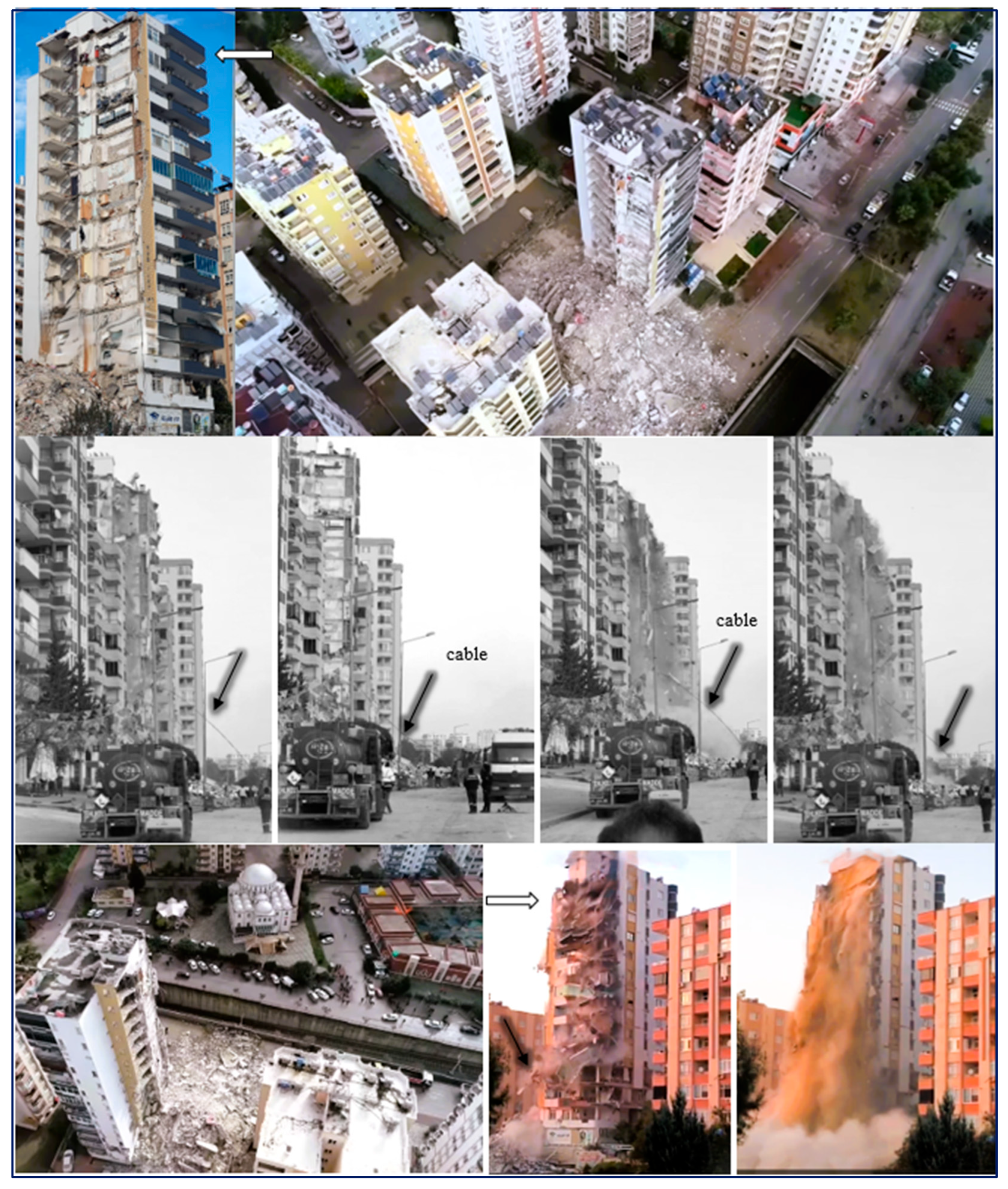
A distinctive case that exemplifies one of the key motivations behind the development of METE, along with its specific demolition method, is presented in
Figure 6. Given the particular conditions, the example constitutes an exceptional and extraordinary case.
4. Analysis: The Importance of Time Interval (Delays) Between Successive Column Explosions
In this section, two specific cases concerning the delay times between successive explosions are examined. Drawing upon real-world demolition experiences, it is deemed important to address these aspects in order to better capture the influence of blasting sequence design on structural response and debris distribution. In
Section 4.1 and
Section 4.2, a 23-story reinforced concrete building is numerically modeled under two different demolition scenarios, using the same structural configuration for both cases.
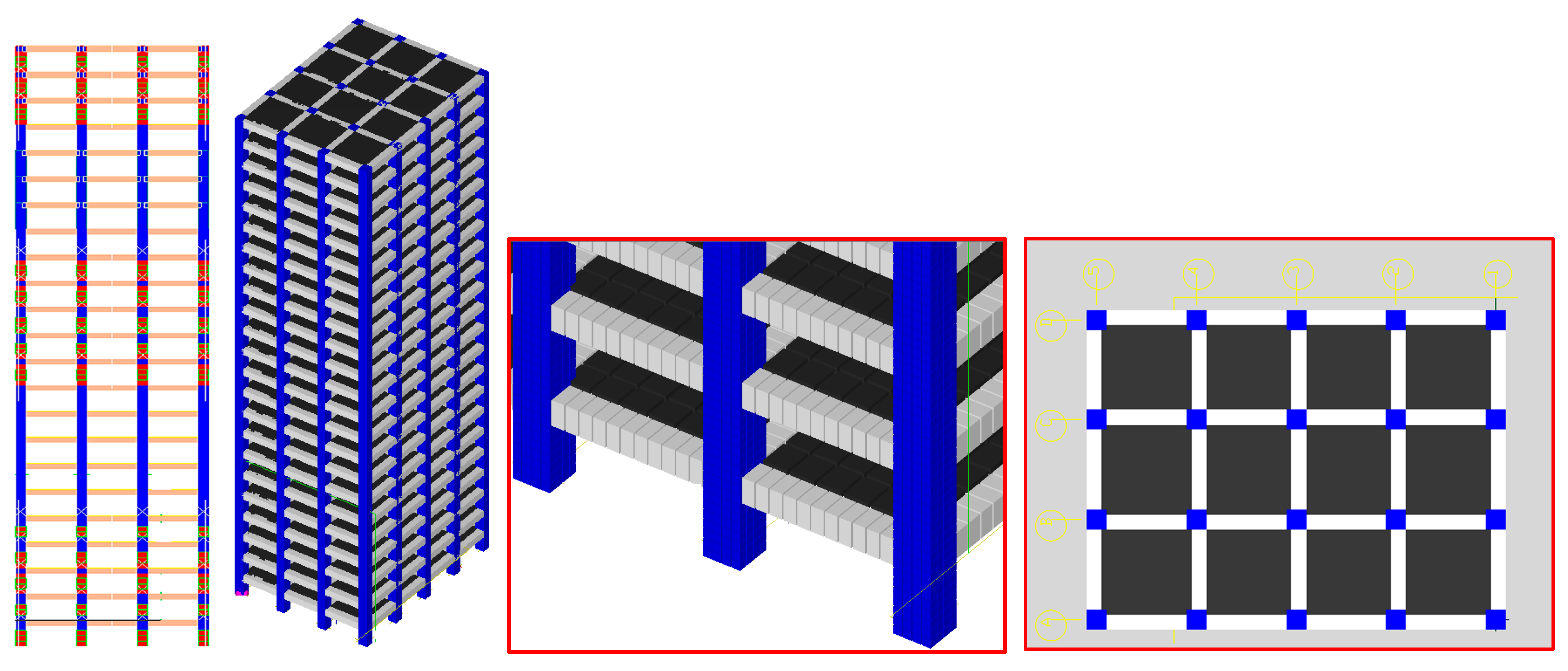
The building has a plan layout of 4 × 3 bays, with bay spans of 6 m in both orthogonal directions. Columns have cross-sectional dimensions of 120 × 120 cm, beams measure 90 × 90 cm, and slabs are 20 cm thick. The story height is constant at 3 m for all floors, and the building is fully fixed to the ground. All structural components are modeled using solid elements (
Table 2). The concrete compressive strength is taken as C40 MPa, while the reinforcement steel yield strength is S420 (420 MPa) (
Table 3). In
Section 4.1, a delay system between consecutive floors is implemented in the blasting sequence, whereas in
Section 4.2, delays are applied between consecutive axes along the building’s elevation. For both cases, the structural response is discussed in conjunction with representative real-world examples, providing insights into the effects of each delay strategy on overall collapse behavior.
The analyses were conducted has five time-step of 0.001 s (1 ms), which ensures numerical stability and adequately captures the rapid transient phenomena during progressive collapse. With respect to loading conditions, concentrated loads were applied; however, since all superimposed live loads are removed before demolition, only the self-weight of the structure was considered in the simulations. To achieve reliable load transfer, the discretization of structural components was designed such that the particles and elements remained geometrically compatible across the mesh. For damping, a constant value of 3% of critical damping was applied, which lies within the widely accepted range of 1–5% for reinforced concrete structures [
13,
20,
21,
27].
Regarding mesh convergence, preliminary trials revealed that low-meshed or excessively coarse models exhibited abnormal behavior and unrealistic failure patterns [
1,
2]. Therefore, meshing was refined according to two criteria: Potential plastic hinge regions were discretized by adopting approximately half of the member section depth as the target segment length. For instance, beams with a 90 cm section depth were divided into segments of ~45 cm, resulting in 11 elements along a 4.8 m span (43.6 cm per segment). Then, the floor slabs were discretized consistently into a 6×6 mesh configuration to ensure compatibility with beams. Geometric consistency between beams and columns was preserved. Columns with a section dimension of 120 cm were discretized by considering potential plastic hinge locations, corresponding to approximately half of the section depth (≈60 cm). Based on this criterion, the longitudinal axis of the columns was subdivided into 10 segments (rather than 5, in order to improve the resolution of hinge formation), while the transverse axis was divided into 4 segments to ensure compatibility with the 90 cm beam discretization (
Figure 7b). This meshing strategy was aimed at achieving consistent refinement between beams and columns, as well as between slabs and beams, thereby enhancing the reliability of the simulated collapse mechanisms while maintaining computational efficiency [
13,
20,
21,
27].
Table 3 summarizes the mechanical properties of the concrete and reinforcing steel employed in the numerical model, including their elastic, strength, and density parameters used for the structural analysis.
The detailed material constants, contact parameters, and interface settings are provided in
Table 4 and
Table 5, which collectively define the constitutive response and failure mechanisms. Concrete (C40) and steel (S420) were represented using linear elastic constitutive models, while the progressive collapse behavior was captured through the strain-based separation of inter-element springs. Specifically, potential failure locations were governed by the separation strain parameters listed in
Table 4, which define the threshold at which the connecting springs between adjacent elements are considered broken.
Following spring separation, the contact behavior between elements was activated, with frictional interactions and contact stiffness controlled by the parameters reported in
Table 4 (friction coefficient) and
Table 5 (normal and shear contact stiffness factors). This approach allows for a realistic simulation of cracking, hinge formation, and progressive collapse, while maintaining consistency between beams, columns, and slabs.
4.1. Delay Between Consecutive Floors in Blasting Sequences
In this scenario, the 23-story building is configured such that explosives are placed on selected floors following a patterned sequence. Specifically, the first 5 stories are charged with explosives (denoted as 5e), followed by 5 consecutive stories without charges, then another 5 explosive-charged stories, 5 empty stories, and finally the top 3 stories with explosives, resulting in the sequence 5e–5–5e–5–3e (Scenario a). Each blasting stage is separated by a delay time of 100 milliseconds (ms), applied between successive floors rather than between structural axes. The numerical representation of the explosive placement sequence (
Figure 7a), along with the corresponding 3D building model (
Figure 7b) and the plan view, is presented in
Figure 7c.
Figure 8 illustrates the step-by-step solid simulation results as well as a real-world example of a demolition employing a similar sequence, serving as the motivating point for this analysis. The chosen delays are intended to replicate realistic operational conditions, ensuring that the numerical simulations closely represent actual demolition practices. As can be inferred from the results, in such demolition patterns, particularly when a relatively short delay time is used, there exists a significant risk of floors failing to topple individually and instead collapsing onto each other. In such cases, the mechanical arm used for post-demolition debris separation faces considerable challenges, especially for high-rise structures where the pile height becomes substantial. As indicated in
Section 4.1, the maximum reach height of demolition machinery varies depending on the model and manufacturer; however, standard lattice boom demolition machines typically have a reach capacity of 20–30 m, making debris handling increasingly difficult as pile height grows. Furthermore, when the structure remains more intact rather than fragmenting, debris removal becomes even more challenging.
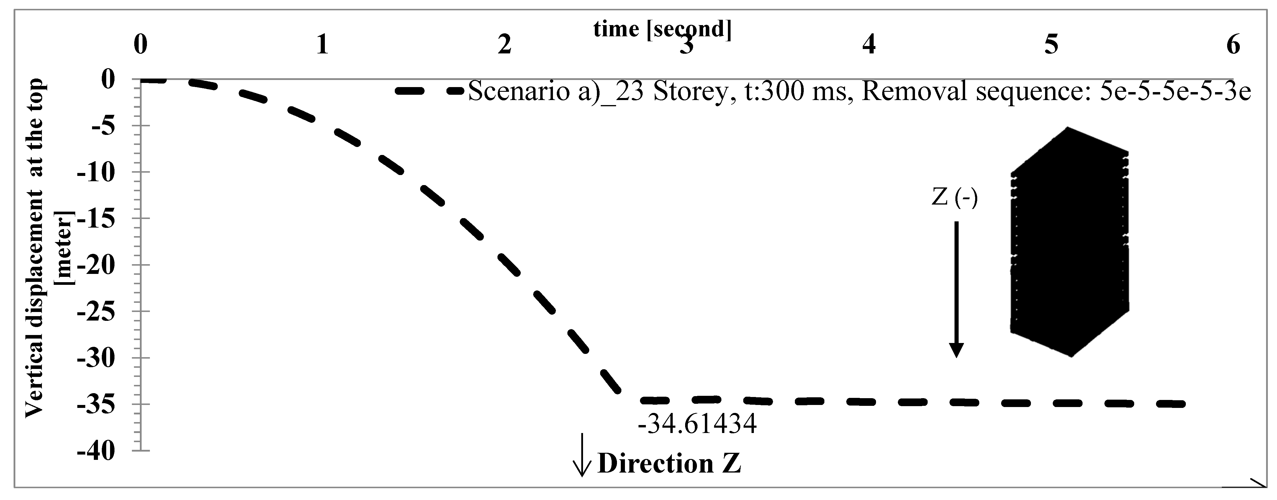
Figure 9 depicts the vertical displacement history (Z-direction) of the roof tip point for the demolition sequence examined in
Section 4.1. The point, initially located at a height of 69 m, underwent a total downward displacement of approximately 34.64 m along the
Z-axis throughout the collapse.
4.2. Delay Between Consecutive Axes in Elevation for Blasting Sequences
In this case, the demolition sequence is designed by applying time delays between consecutive axes along the building’s elevation, with the primary objective of inducing a controlled toppling of the structure. The building has five longitudinal axes, and explosives are placed selectively along these axes following the pattern 20–16–13–7 (denoting the number of removed columns per axis from the bottom up). The delay time between successive axes is set at 300 ms, such that the first axis is detonated at 0 ms, the second at 300 ms, and the third and fourth axes simultaneously at 600 ms.
This configuration promotes a progressive collapse mechanism by sequentially removing supports, weakening the equilibrium toward the desired direction, and allowing the center of mass to shift accordingly, thereby directing the structure to topple toward a predefined path.
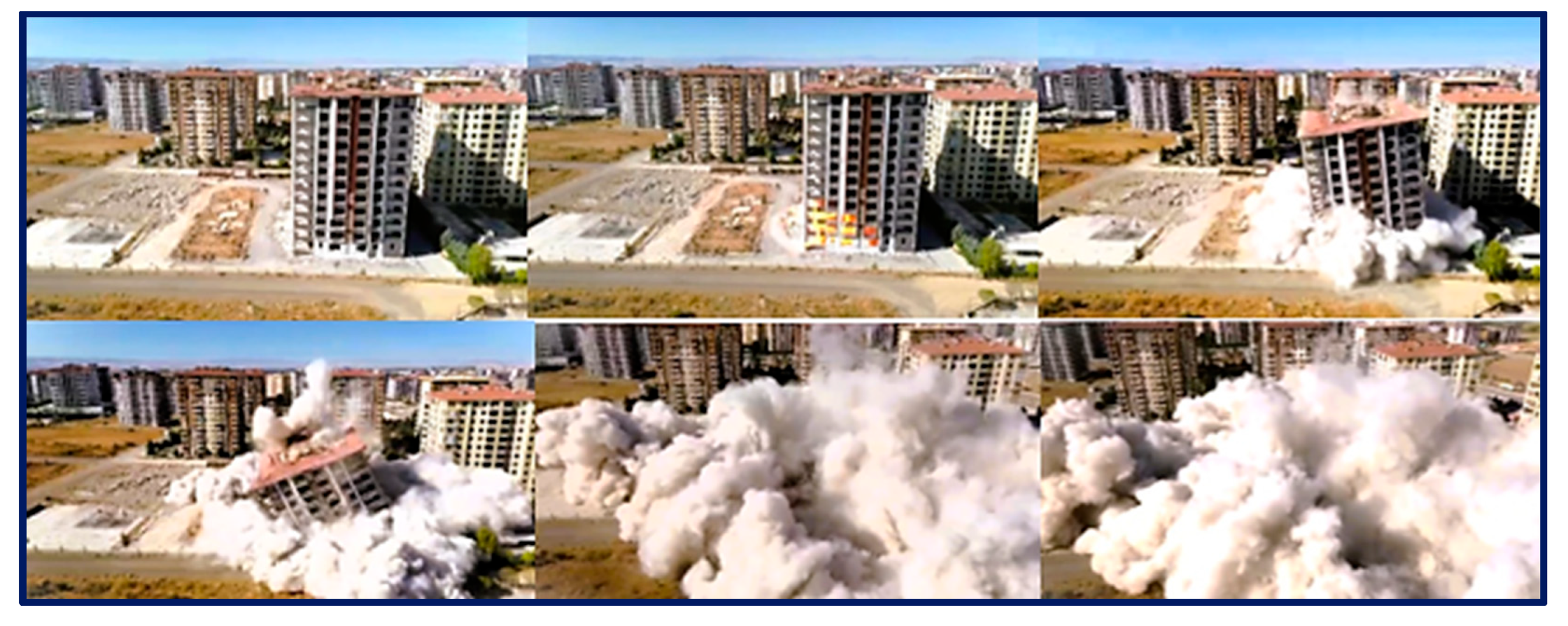
Figure 10 illustrates the step-by-step solid simulation output together with a representative real-world example employing a comparable blasting arrangement in
Figure 11. The results demonstrate that axis-by-axis delay application can effectively control the collapse direction and reduce the likelihood of vertical piling. This approach can be particularly advantageous in dense urban environments, where limiting debris spread and protecting adjacent structures are of critical importance.
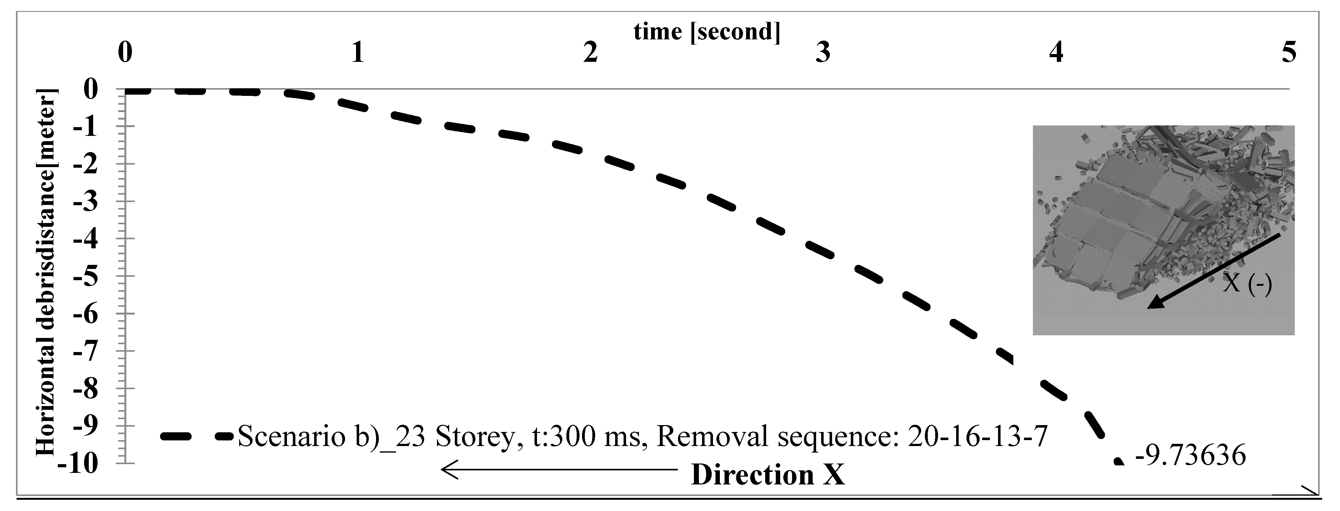
Figure 12 presents the horizontal displacement history (X-direction) of the roof tip point for the toppling scenario described in
Section 4.2. In this case, the point experienced a lateral translation of approximately 9.73 m along the
X-axis, reflecting the controlled horizontal movement generated by the axis-by-axis blasting sequence. It is important to emphasize that, in the previous scenario, the principal outcome of the demolition was the accumulated debris height; hence, the vertical displacement in the Z direction was measured (
Figure 7). By contrast, in the toppling scenario, due to the lateral overturning of the structure, the maximum horizontal extent of the debris in the X direction was quantified (
Figure 12).
4.3. Conclusions of Conducted Explicit Nonlinear Analysis
In this section, two demolition scenarios were investigated for the same 23-story reinforced concrete building, differing both in the application of delay times and the blasting sequence: (i) delays applied between consecutive floors with a specific floor sequence (
Section 4.1) and (ii) delays applied between consecutive axes along the building elevation with a defined axis sequence (
Section 4.2). The building, with a constant story height of 3 m, fixed-base boundary conditions, and a 4 × 3 bay configuration, was modeled using solid elements and realistic material properties (C40 concrete, S420 reinforcement).
In the consecutive-floor sequence, explosives were arranged according to a 5e–5–5e–5–3e pattern, with a 100 ms delay between successive floors. Simulation results (
Figure 7,
Figure 8 and
Figure 9) showed that, under this floor sequence and delay configuration, there is a significant risk of floors collapsing onto each other, particularly with shorter time intervals, which complicates post-demolition debris handling. The vertical displacement of the roof tip point (
Figure 9) reached approximately 34.64 m downward along the
Z-axis from its initial height of 69 m.
In the consecutive-axis sequence scenario, explosives were distributed along five longitudinal axes according to the 20–16–13–7 column pattern, with delays of 0 ms, 300 ms, and 600 ms applied sequentially. This axis-by-axis sequence successfully directed the collapse laterally, with the roof tip point moving approximately 9.73 m along the
X-axis (
Figure 12). The resulting debris spread was substantially lower than the guideline limit indicated in
Figure 3, emphasizing the importance of performing building-specific simulations for precise collapse prediction and risk mitigation.
The major findings from the two 23-story building simulations presented in the study indicate that both the blasting sequence and the associated delays critically influence collapse behavior. Specifically, it was seen that applying an axis-by-axis sequence is more advantageous than a floor-by-floor sequence in these cases; however, since the behavior may differ in other cases, the importance of building-specific modeling has been emphasized. Although the floor-by-floor sequence did not yield an efficient outcome in the example of the internal collapse scenario, it could potentially perform better in structures with different characteristics, such as older buildings with lower material strength or in scenarios where explosives are applied across more floors. Therefore, these results highlight the sensitivity of progressive collapse to delay timing and sequencing, underlining the need for careful calibration of demolition strategies for each case. For both scenarios, real-life applications have been presented in
Figure 8 and
Figure 11. Another important point is that the formulation given in Equation (1) defines the worst-case scenario for the debris reach. Based on this expression, the obtained results for a 23 m building remain well below 66 m. It should be noted that the current formulation provides a very conservative limit; however, it is recognized that with extensive real-life validation, calibration, and numerous parametric analyses, the formula can be systematically refined and improved in the future. Lastly, it should be noted that the definition of debris reach presented here does not encompass cases where an incorrect type of explosive was used, as abnormal projections can occur due to blast effects. In particular, scenarios in which explosives were placed on certain floors without the use of protective safety measures are not covered by this formulation.
4.4. Limitations of the Analytical Study
Given the inherent complexity of demolition dynamics, it is acknowledged that further investigations using additional case studies and high-fidelity, solid, explicit, time-dependent nonlinear analyses are essential to reliably predict and optimize controlled demolition performance. Moreover, the results of the present study apply only to structures with characteristics that fall within its defined scope.
5. Fundamentals of Controlled Demolition: Key Procedures
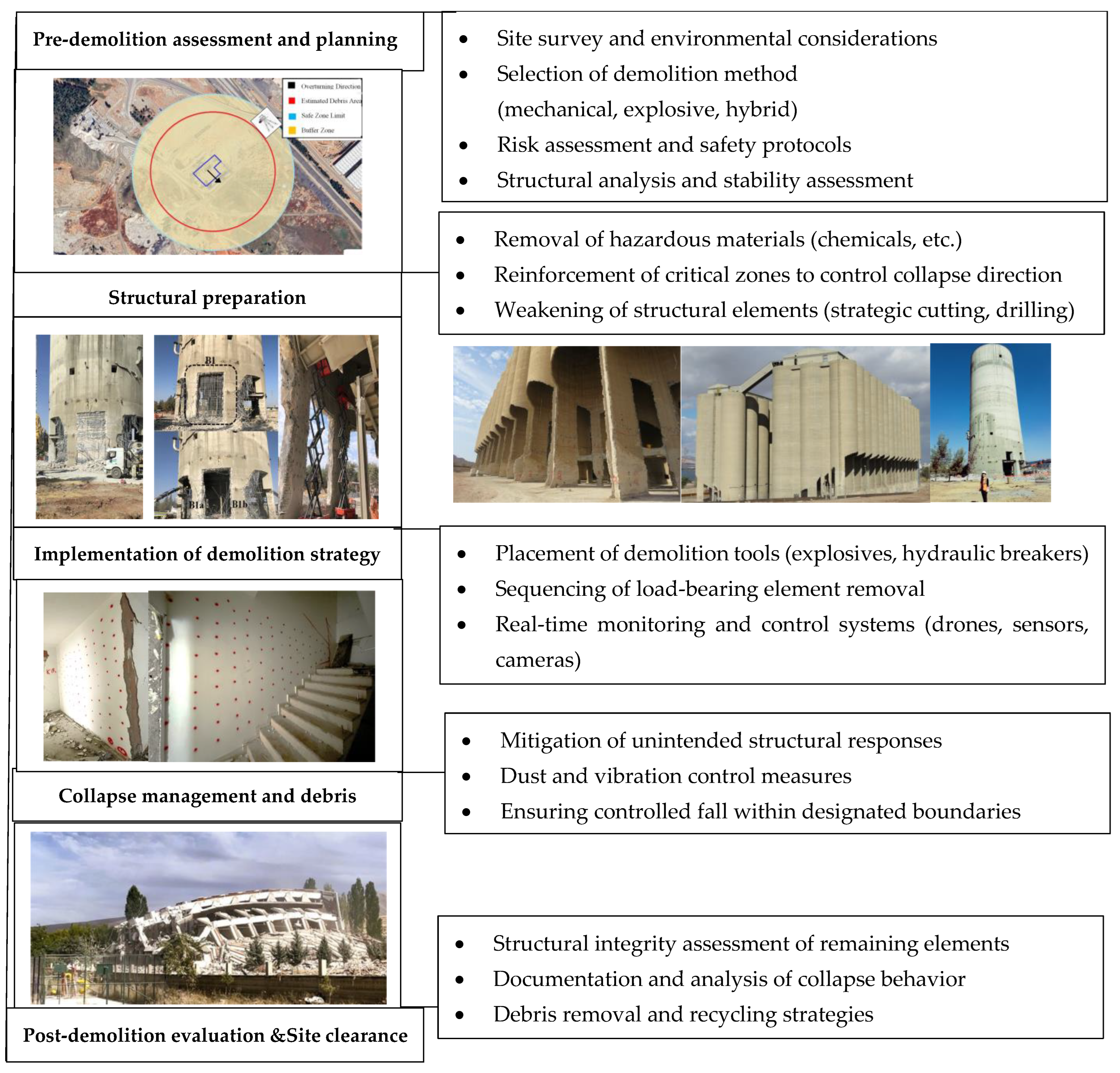
Controlled demolition is a meticulously planned process that ensures structural removal while minimizing risks to the surrounding environment. Unlike uncontrolled collapse, this method relies on precise engineering calculations, strategic sequencing, and advanced monitoring technologies. The demolition process can be broken down into five critical phases, each playing a vital role in ensuring efficiency and safety.
1-Pre-demolition assessment and planning: Every successful demolition project begins with thorough assessment and planning. Structural analysis and stability evaluations are essential to understanding load distribution and potential collapse mechanisms. Additionally, site surveys and environmental considerations help determine the most appropriate demolition method—mechanical, explosive, or hybrid. Safety remains a top priority, necessitating rigorous risk assessments and the development of protective protocols to safeguard workers, nearby structures, and the public.
2-Structural preparation: Before demolition can commence, the structure must be systematically weakened to ensure a controlled collapse. This phase involves the removal of hazardous materials, such as chemicals and asbestos, which could pose health and environmental risks. Additionally, critical structural elements undergo strategic weakening through precision cutting and drilling, while key zones are reinforced to control collapse direction. These preparatory measures reduce unpredictability and enhance the efficiency of the demolition process.
3-Implementation of the demolition strategy: Once the structure has been adequately prepared, the actual demolition strategy is executed. The placement of demolition tools—ranging from explosives to hydraulic breakers—must follow a carefully designed sequence to achieve the desired collapse pattern. Load-bearing elements are removed in a controlled manner, and real-time monitoring systems, including drones, sensors, and high-speed cameras, provide crucial feedback during the process. These technological advancements enable engineers to make adjustments in real time, enhancing precision and safety.
4-Collapse management and debris control: Managing the collapse itself is just as important as initiating it. Unintended structural responses must be mitigated to prevent unpredictable damage. Dust and vibration control measures are implemented to minimize environmental and structural impact on surrounding buildings. Additionally, ensuring that the structure falls within designated boundaries requires meticulous planning and execution. Without these precautions, secondary damage and safety hazards could compromise the integrity of the entire operation.
5-Post-demolition evaluation and site clearance: Demolition does not end with the collapse of a structure; rather, the final phase is crucial for project completion. A structural integrity assessment of remaining elements should be conducted to verify safety before site clearance begins. Engineers analyze the collapse behavior to refine future demolition techniques, contributing to the advancement of the field. Additionally, debris removal and recycling strategies play a pivotal role in sustainable demolition practices, reducing waste and promoting environmental responsibility.
By integrating engineering expertise, strategic planning, and cutting-edge monitoring technologies, controlled demolition ensures a balance between efficiency, safety, and environmental responsibility (
Figure 13). Each phase of the process builds upon the previous one, emphasizing precision and minimizing risk. As demolition techniques continue to evolve, the integration of modern innovations will further refine the ability to dismantle structures with unprecedented accuracy and safety.
6. Controlled Demolition: Advanced Analysis Framework and Future Prospects
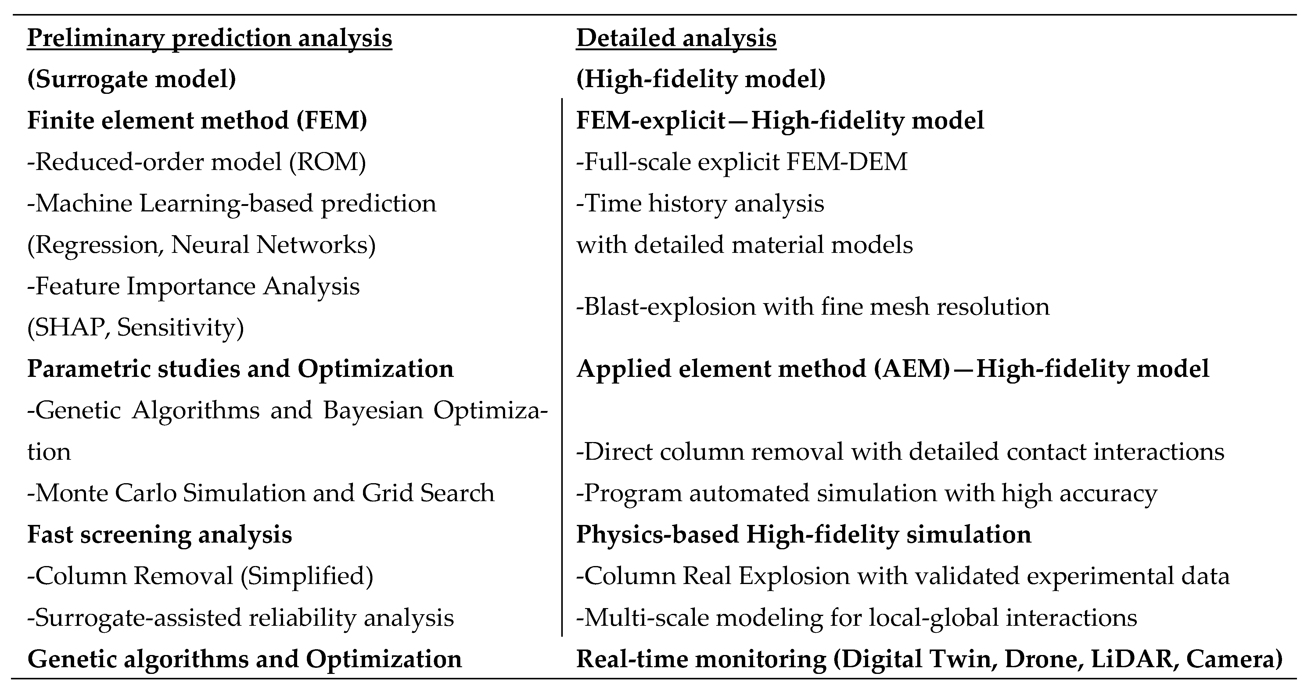
Controlled demolition is a multifaceted process involving several stages, ranging from preliminary prediction to detailed analysis and real-time monitoring. This proposed framework outlines a structured approach that integrates both low-fidelity and high-fidelity models, optimization techniques, and real-time data collection [
28] and processing to potentially enhance the efficiency and safety of demolition operations.
The process begins with “Preliminary Prediction Analysis”, where low-fidelity surrogate models rapidly predict the structure’s response to demolition. This phase often employs the Finite Element Method (FEM) combined with reduced-order models (ROM) [
29,
30] such as modal reduction or proper orthogonal decomposition, which provide fast yet reasonably accurate approximations of structural behavior. Additionally, Machine Learning (ML)-based prediction techniques—including regression models and neural networks—can process historical demolition records or simulation datasets to generate predictions for future scenarios. These approaches enable quick screening and preliminary assessments without requiring extensive computational resources. Furthermore, feature importance analysis tools, such as SHapley Additive exPlanations (SHAP) and sensitivity analysis, help identify the key variables influencing debris distribution and structural stability [
31,
32,
33]. Parametric studies and optimization methods, including Monte Carlo simulations and grid search algorithms, can be used to explore various demolition scenarios and guide the selection of the most effective strategy while accounting for uncertainty and variability [
34,
35].
Following preliminary analysis, the framework advances to the “Detailed Analysis” phase, where high-fidelity models provide a comprehensive understanding of the demolition process. Nonlinear, time-dependent explicit FEM simulations are particularly important, as they enable the accurate representation of complex material behavior, progressive damage, and dynamic interactions between structural elements [
36,
37,
38,
39,
40]. Time-history analyses can be performed to assess the dynamic response of structures during demolition [
1,
2]. By incorporating advanced material models and fine mesh resolutions, these simulations allow time-history analyses to be performed, providing a high-fidelity assessment of the dynamic response of structures during demolition. Full-scale simulations provide detailed insights into the effects of blast explosions, structural damage, and debris behavior under varying conditions.
Furthermore, the Discrete Element Method (DEM) is a numerical framework specifically developed to capture the discontinuous and heterogeneous nature of materials whose mechanical behavior is governed by discrete interactions at the microscale. Unlike continuum-based methods such as the Finite Element Method (FEM), Finite Difference Method (FDM), or Boundary Element Method (BEM), DEM explicitly represents the material as an assembly of rigid or deformable particles that interact through contact laws [
41,
42,
43,
44,
45]. This approach is particularly advantageous for simulating geomaterials such as rock, concrete, and granular soils, where microstructural heterogeneity, porosity, and anisotropy strongly influence macroscopic responses. This capability makes DEM particularly effective in simulating structural collapse behavior, as it can naturally capture crack initiation, progressive fragmentation, and debris interaction during failure processes.
In DEM, the motion of each particle i is governed by Newton’s second law of motion for translational and rotational degrees of freedom:
The translational motion is presented in Equations (2) and (3):
mi and Ii are the mass and moment of inertia of particle i,
ui and θi are the translational and rotational displacement vectors,
Fci is the resultant contact force from particle–particle and particle–wall interactions,
Fgi is the gravitational force,
Fexti represents other externally applied forces,
Mci is the contact moment,
Mexti represents externally applied moments.
The Contact Mechanics Formulation is presented in Equations (4) and (5):
The contact force F
ci is decomposed into normal and tangential components:
where
kn, kt are the normal and tangential stiffness coefficients,
δn is the normal overlap,
δt is the tangential displacement vector accumulated during the contact,
ηn, ηt are the damping coefficients,
vn and vt are the relative normal and tangential velocities,
n^ is the unit vector along the contact normal.
Frictional resistance is enforced through the Coulomb friction criterion (Equation (6)):
where μ is the coefficient of friction between particles.
Time Integration:
DEM adopts an explicit time-stepping algorithm, often based on the central difference method (Equations (7) and (8)):
The stable time step Δt is constrained by the Rayleigh wave propagation limit (Equation (9)):
where R is the smallest particle radius and c
s is the shear wave velocity in the particle material.
The primary strength of DEM lies in its ability to naturally reproduce crack initiation, propagation, and coalescence without additional fracture criteria. Progressive damage processes—such as crack nucleation, growth, and merging—can be captured at the particle scale and linked directly to macroscopic failure modes. This capability makes DEM particularly effective in rock mechanics, concrete fracture analysis, blast simulation, and granular flow problems.
However, DEM’s computational demand is significant. As the particle size decreases to improve resolution, the number of particles increases cubically, and the critical time step decreases proportionally. This results in a rapid escalation of simulation cost, often requiring high-performance computing resources for large-scale problems.
To further enhance the understanding of localized structural behavior during demolition, the Applied Element Method (AEM) can be incorporated. AEM provides detailed insights into fracture propagation, element interactions, and progressive failure mechanisms [
46,
47,
48,
49]. AEM combines concepts from the Finite Element Method (FEM) and the Discrete Element Method (DEM), discretizing a structure into small rigid elements connected by pairs of normal and shear springs placed along their shared surfaces. These springs represent the material’s stiffness and are capable of reproducing both continuous deformation and complete disconnection when failure criteria are reached.
In AEM, each element is treated as a rigid body with six degrees of freedom in 3D (three translational and three rotational), and its motion is governed by Newton’s equations of motion:
Translational motion (Equations (10) and (11)):
mi, Ii are the mass and moment of inertia of element i,
ui, θi are its translational and rotational displacements,
ΣFci and ΣMci are the total contact forces and moments from connected springs,
Fgi, Fexti, Mexti are gravitational and external loads.
Spring Formulation
Each pair of adjacent elements is connected by normal and shear springs distributed along their interface. The force–displacement relations for these springs are [
46,
47,
48,
49]:
Normal direction (Equation (12)):
Shear direction (Equation (13)):
where
kn = E·A/L is the normal stiffness,
kt = G·A/L is the shear stiffness,
E and G are the Young’s modulus and shear modulus,
A is the tributary area of the spring,
L is the initial length between element centroids,
Δun and Δut are relative normal and tangential displacements.
When a spring reaches its tensile, compressive, or shear failure limit, it is removed from the model, allowing separation or collapse to occur naturally. The failure criteria are typically based on material strength parameters (ft, fc’, τmax).
After disconnection, elements may collide with each other or surrounding boundaries. These collisions are handled using contact detection algorithms, and contact forces are computed using impact laws that include stiffness and damping terms, similar to DEM contact formulations.
Time Integration:
AEM employs an explicit time integration scheme for dynamic analysis, Equations (14) and (15):
Compared to DEM, AEM typically requires fewer elements for large-scale structures while retaining the ability to model separation and collision with high accuracy. AEM allows simulation of structural behavior from the intact state to complete disintegration, capturing fracture propagation, element separation, and debris motion. This makes it highly suitable for progressive collapse analysis [
46,
47,
48,
49].
This method is particularly effective for simulating complex separation phenomena, such as crack initiation and propagation, which are difficult to capture with traditional FEM. Direct column removal simulations can be performed within this framework, incorporating detailed contact interactions to evaluate the impact of each removal step on overall structural stability and collapse progression (
Figure 14).
These simulations can be validated against real-world experimental or monitored data, thereby improving confidence and supporting informed decision-making in demolition strategy development.
In addition, Genetic Algorithms and Bayesian Optimization can be employed to optimize the demolition process, ensuring that the most efficient and effective strategies are selected [
50,
51,
52,
53,
54]. Surrogate-assisted reliability analysis can further enhance the accuracy of optimization by using low-fidelity models to guide the search space toward optimal solutions [
55,
56,
57,
58]. As the demolition process progresses, automation and optimization techniques become increasingly critical. Algorithms can help determine the optimal sequence of detonation or removal, minimizing unintended damage and improving control.
A key component of modern demolition practices is the integration of Real-Time Monitoring, which significantly enhances both the safety and adaptability of operations. Technologies such as Digital Twin models [
58,
59,
60,
61], drone UAV-based imagery [
62,
63], and LiDAR sensors [
64,
65,
66,
67,
68] can provide continuous monitoring of the demolition site. These systems supply real-time feedback, allowing engineers to adapt plans dynamically in response to structural behavior.
Deep Learning (DL)-based image analysis plays a crucial role in the conceptual development of real-time monitoring systems for controlled demolition. For instance, Convolutional Neural Networks (CNNs) can be trained to process video feeds in order to detect and track critical structural components during collapse. CNNs can be designed to process visual inputs—such as video frames captured by drones or surveillance cameras—in order to detect and track critical structural elements for collapse scenarios [
69,
70,
71,
72]. This capability could allow for the observation of debris trajectories, slab displacements, and failure patterns. CNNs operate by applying various filters—such as edge detection, sharpening, and blurring—to extract spatial features while reducing image dimensionality. In CNN architectures, convolutional layers apply a set of filters (e.g., edge detectors, Gaussian blur, sharpening kernels) that extract meaningful spatial features such as edges, contours, or textures. These features are then passed through pooling layers, which reduce the spatial dimensions of the data (e.g., using max pooling or average pooling) to decrease computational cost while preserving essential characteristics.
After multiple layers of convolution and pooling, CNNs often employ a Softmax activation function in the final classification layer. Softmax transforms the network’s outputs into a probability distribution across various classes—such as identifying slabs, beams, or debris types—thus enabling probabilistic decision-making for scene interpretation. To further increase robustness, image augmentation techniques (e.g., random rotation, flipping, brightness adjustment, and noise injection) are often employed during training. This improves generalization across various lighting conditions, angles, and environmental variables encountered during demolition. The extracted features from CNNs can then be used within larger machine learning pipelines to facilitate scalable and data-efficient structural analysis, especially when dealing with large volumes of visual input. These methods synthetically expand the dataset, helping the model generalize better across varying lighting, camera angles, and demolition conditions.
To enhance both object recognition and localization, the integration of YOLO (You Only Look Once) models has been widely proposed. To further improve object recognition and localization capabilities, YOLO models may be integrated into such systems. YOLO performs real-time detection by processing an entire image in a single pass, identifying multiple objects and their bounding boxes efficiently. This capability is particularly valuable in dynamic, high-risk environments where the rapid evolution of structural states must be tracked without latency. YOLO’s ability to detect multiple structural components in a single frame with high speed and accuracy makes it particularly well-suited for rapidly evolving environments like controlled demolition scenarios [
73,
74].
Beyond traditional vision models, the integration of Vision-Language Models (VLMs) offers new possibilities for semantic scene understanding. Tools like the Segment Anything Model (SAM) can segment any object within an image, including those unseen during training. When combined with Grounding DINO, which aligns natural language descriptions with visual targets, this system can automatically detect and segment structural elements described in human language. For instance, a command such as “the top-right column with visible sensors” can trigger the system to isolate and monitor the specific structural component—even if it is partially obscured or captured at a distance.
Such approaches offer significant advantages for enhancing image clarity and contextual understanding in complex demolition sites, particularly when visual data is collected from afar using drones. By integrating SAM and Grounding DINO, future systems could not only improve segmentation accuracy but also adjust and refine the perceived clarity of distant or degraded objects—thereby increasing the actionable value of remote visual data. These advanced tools can convert ambiguous visual data into actionable information for decision-makers.
In addition to Deep Learning (DL) models, ensemble-based machine learning algorithms like XGBoost (Extreme Gradient Boosting) offer complementary benefits on the predictive side. XGBoost constructs multiple decision trees in a sequential manner, where each new tree is trained to minimize the residual errors of the previous ones. Unlike conventional regression methods that rely on Mean Squared Error (MSE), XGBoost utilizes a regularized objective function that incorporates both first-order gradients and second-order Hessian information. This allows for more stable and accurate learning, particularly in noisy environments. When trained on structural sensor data and simulation outputs, XGBoost models can support early warning systems by estimating the likelihood of failure sequences or unexpected deviations in collapse behavior [
75,
76].
Although this study does not implement or validate these AI-driven systems, it outlines their conceptual potential for future integration into intelligent demolition frameworks. The proposed vision includes a multi-layered feedback system where deep learning, image segmentation, and predictive modeling converge to enable smarter, safer, and more responsive demolition processes. It emphasizes the future potential of integrating CNNs, YOLO, and XGBoost into real-time monitoring and control frameworks [
77,
78,
79,
80]. When coupled with sensor networks and simulation data, these tools could one day support dynamic feedback systems designed to flag anomalies in collapse behavior and guide responsive decision-making.
Ultimately, by integrating tools such as CNN, YOLO, SAM, Grounding DINO, and XGBoost—along with simulation and sensor data—future controlled demolition strategies may evolve into intelligent, data-driven operations. These would allow engineers to not only plan dismantling sequences with greater confidence but also to adapt dynamically to real-time site conditions. The framework discussed herein lays the conceptual groundwork for such advancements, supporting a shift from reactive to proactive demolition methodologies. Multi-scale modeling strategies that combine high-fidelity simulations with surrogate models may offer a balanced approach, capturing both local and global structural responses while maintaining computational efficiency.
In conclusion, this advanced framework for controlled demolition outlines a comprehensive methodology that synthesizes predictive tools, optimization strategies, and visual monitoring concepts. The AI-based techniques discussed herein provide a conceptual foundation for future research aiming to enhance safety, precision, and adaptability in the controlled dismantling of urban structures. Consistent with the structure of the preceding sections, the processes presented in
Section 6, Advanced Analysis Framework and Future Prospects, are synthesized in the flowchart below to enhance conceptual clarity and support systematic comprehension by the reader (
Figure 15).
This framework represents a detailed approach to controlled demolition, combining predictive analysis, detailed simulation, and real-time monitoring to ensure safe and efficient operations. By integrating state-of-the-art technologies and methodologies, this approach enables the accurate prediction, optimization, and validation of controlled demolition scenarios, paving the way for safer and more efficient demolition practices in the future.
7. Conclusions
This study introduces an integrated and forward-thinking framework for controlled demolition by combining traditional methods with advanced numerical modeling, artificial intelligence (ML, DL, CNNs), and real-time monitoring technologies (UAV, LiDAR). The framework offers a structured and scalable solution for planning and executing demolition operations with high precision, safety, and adaptability. By bridging field experience with simulation-based predictions, it provides a practical foundation for evolving demolition science in line with the needs of modern urban environments.
The conclusions can be structured as follows:
Numerical simulations play a central role in this framework by enabling detailed prediction of progressive collapse mechanisms, blast effects, and sequential column removals. In
Section 4, two demolition scenarios were investigated for a 23-story reinforced concrete building, differing in both blasting sequence and the application of delays: (i) delays applied between consecutive floors following a 5e–5–5e–5–3e pattern with 100 ms intervals (
Section 4.1) and (ii) delays applied between consecutive axes along the building elevation according to a 20–16–13–7 column pattern with 0–300–600 ms intervals (
Section 4.2). These simulations allowed detailed observation of collapse dynamics, including vertical (Z-direction) and horizontal (X-direction) displacements of the roof tip point, highlighting how sequence design and delay timing critically influence structural behavior during demolition.
When these specific cases are considered, simulations indicate that an axis-by-axis demolition sequence outperforms floor-by-floor delays in controlling lateral collapse and minimizing floor-to-floor impacts. In the axis-by-axis scenario, the roof tip displaced ~9.73 m along the
X-axis (
Figure 9 vs.
Figure 12), well below guideline-recommended distances (
Figure 3), while the floor-by-floor sequence resulted in a vertical displacement of ~34.64 m (
Z-axis), increasing the risk of piling. These results underscore the importance of building-specific simulations. Further explicit, time-dependent nonlinear analyses are recommended to enhance predictive accuracy and operational safety in complex urban environments.
Digital twins integrated with real-time structural feedback can provide a dynamic layer of monitoring and may support adaptive decision-making during demolition. Drone-based photogrammetry and LiDAR scanning can offer accurate 3D models, particularly useful for aging or incompletely documented structures. AI-based object detection and tracking can contribute to monitoring debris trajectories, identifying displacements, and supporting autonomous documentation.
Flowcharts developed in this study support engineers and decision-makers in evaluating alternative demolition methods, sequencing operations, and planning contingencies. These visual decision-making aids increase clarity, especially in multidisciplinary settings, and facilitate coordination between engineering teams, contractors, and safety personnel.
Overall, the framework provides a systematic, data-driven methodology for informed decision-making in demolition operations. Insights from case studies, parametric analyses, and comparative evaluations offer a comprehensive perspective on controlled demolition strategies.
