Abstract
This study experimentally investigates the mechanical and dynamic hygrothermal behavior of compressed earth block (CEB) walls subjected to simulated climatic cycles representative of a tropical humid environment. Four formulations were tested: raw soil (D0), soil with kenaf fibers (DF), soil with fibers and cement (DFC), and soil with fibers, cement, and slag (DFCL). Performance was assessed in an instrumented bi-climatic cell, enabling the determination of thermal and hygroscopic attenuation factors and time lags, complemented by standardized uniaxial compression and three-point bending tests. DFCL achieved a compressive strength of about 10 MPa, nearly twice that of DF (~6 MPa), exceeding the threshold required for buildings up to R + 1. Regarding hygrothermal behavior, DFCL exhibited the highest thermal attenuation factor (2.24) and a hygroscopic attenuation factor of 2.05, with corresponding time lags of ~0.9 h (thermal) and ~1.1 h (hygroscopic). These results highlight superior thermal inertia and moisture regulation, well suited to the constraints of tropical humid climates. Overall, the findings confirm the potential of kenaf fiber-reinforced cement–slag stabilized CEBs as a sustainable construction solution, particularly for load-bearing walls in hot and humid regions. In addition to technical performance, DFCL also offers environmental and economic advantages, as the use of local fibers and slag reduces Portland cement consumption and costs, reinforcing its sustainability potential in tropical contexts.
1. Introduction
The transition towards sustainable construction practices requires the use of locally available materials with low environmental impact, capable of providing satisfactory hygrothermal and mechanical performance. Among these materials, raw earth—used for millennia in various forms (rammed earth, adobe, compressed earth blocks, CEBs)—holds a privileged position due to its low embodied energy, recyclability, and remarkable technical properties, such as high thermal inertia and the ability to regulate indoor humidity [1,2].
In tropical humid climates, such as in Benin, daily temperature amplitudes can exceed 10 °C, while relative humidity may vary by more than 40%. These fluctuations represent a dual challenge: they affect both indoor thermal comfort and building durability but also provide an opportunity to harness the natural regulating properties of raw earth [3]. Under repeated heat and moisture cycles, coupled heat–moisture transfer phenomena [4,5] can alter the microstructure, reduce thermal inertia, and compromise mechanical strength.
Previous studies [6,7,8] have mainly investigated the thermal and hygroscopic properties of CEBs, yet few have experimentally reproduced realistic climatic cycles, particularly under tropical conditions. Moreover, the combined effects of mineral stabilization (cement, slag) and plant fiber reinforcement on the dynamic hygrothermal response of CEBs remain poorly documented, despite evidence that these strategies enhance mechanical strength and mitigate moisture sensitivity [9,10,11]. Typically, unstabilized CEBs exhibit compressive strengths of 1–3 MPa, while stabilized formulations may reach 5–10 MPa. Hygrothermal studies show attenuation factors of 1.5–2.0 under cyclic conditions, depending on soil and stabilization [1,2].
Attenuation factors of 1.5–2.0 were reported for hemp-lime [2], while fiber-stabilized earth blocks showed time lags of 1–2 h [12]. These reference values frame the expected range for bio-composite earth materials and underline the regulatory potential of CEBs in tropical climates.
In this context, the present work aims to evaluate the mechanical, hygrothermal, and energy performance of kenaf fiber-reinforced CEB formulations, with a particular emphasis on their suitability for tropical humid climates. The originality of this study lies in:
- The diversity of tested formulations, including raw earth, fiber-reinforced earth, and fiber–mineral stabilized composites;
- The use of an instrumented bi-climatic cell capable of reproducing realistic temperature and humidity cycles while precisely monitoring dynamic parameters (time lag, attenuation factor);
- An integrated evaluation of mechanical, hygrothermal, and energy performance, providing reference data to support the development of sustainable building solutions for hot and humid climates.
2. Materials and Methods
2.1. Materials
The cement used was CPA-CEM I 42.5 ES (LafargeHolcim, Paris, France), composed of 95% clinker and 5% gypsum. The ground granulated blast furnace slag (GGBFS) was supplied by ECOCEM France (Fos-sur-Mer, France) and complies with NF EN 15167-1:2006. It is classified as Class A slag according to NF EN 206/CN, a classification confirmed on 28 June 2013, by CERIB.
The mixing water was tap water from the GeM laboratory, containing low sulfate content and maintained at 20 ± 1 °C. Its quality complies with the requirements of NFP 18-404.
The kenaf plants originated from Parakou (Benin). They were harvested at the age of six months, retted in a river, and manually defibrated. The fibers were cut using a paper cutter to obtain nominal lengths of 10, 20, 30, 40, 50, and 60 mm, with a tolerance of ±1 mm. Before mixing, the fibers were conditioned at laboratory ambient conditions (20 ± 2 °C; 50 ± 5% RH) for 48 h to stabilize their moisture content. The prepared fibers are shown in Figure 1.
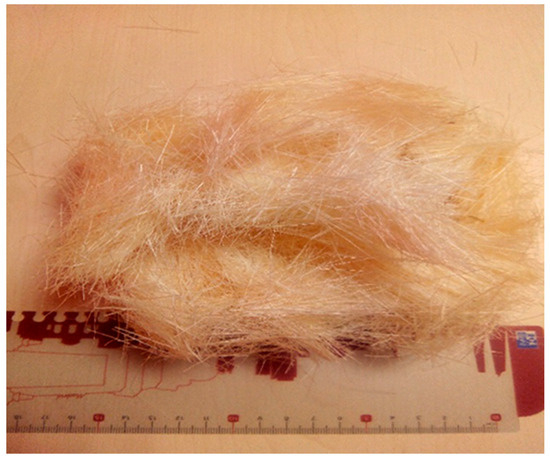
Figure 1.
Photograph of kenaf fibers after preparation and cutting for incorporation in CEB mixtures.
The tensile strength of the kenaf fibers was determined for each length, showing the influence of fiber length on mechanical performance. Each batch was measured and classified with a tolerance of ±1 mm, and the results are presented in Figure 2.
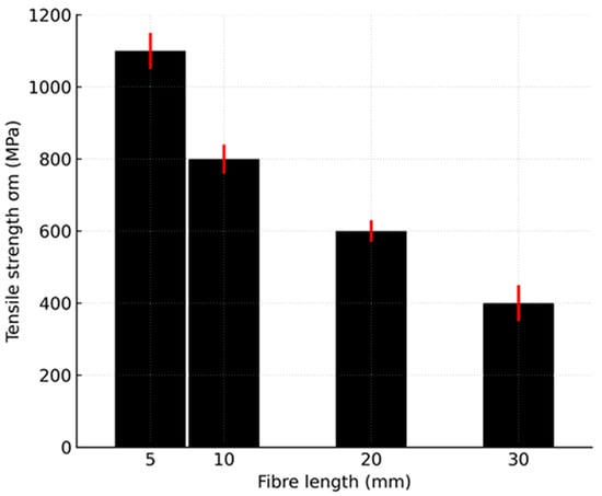
Figure 2.
Effect of fiber length on tensile strength (single-fiber tests). Bars show mean; red whiskers ±1 SD; gauge length L0 = tested fiber length (5, 10, 20, 30 mm).
Single-fiber tensile tests followed ISO 5079 (ASTM D3822 acceptable), with the gauge length (L0) set equal to the tested fiber length (5, 10, 20, 30 mm), pneumatic grips with sandpaper tabs, a crosshead speed of 2 mm·min−1, and specimens conditioned at 23 ± 2 °C and 50 ± 5% RH for 24 h (n = 10 per length). Tensile strength was computed from the maximum load and the optically measured fiber cross-section, and values are reported as mean ± SD; across this range. Strength decreased as fiber length increased (size effect). Based on prior length–content optimization, the mechanically optimal choice—0.5 wt% kenaf fibers at 30 mm—was therefore adopted for the DF, DFC, and DFCL formulations used in the hygrothermal study.
The soil used in this study was locally sourced. Its geotechnical properties were as follows:
- -
- Specific gravity: 2.65 g/cm3
- -
- Atterberg limits: Liquid Limit (LL) = 28%, Plastic Limit (PL) = 14%, Plasticity Index (PI) = 14%
- -
- Methylene blue value (VBS): 1.1 g/100 g
- -
- Proctor Normal test: Optimum dry density (ρ_dopt) = 1846 kg/m3; Optimum moisture content (W_opt) = 12%
2.1.1. Origin and Characteristics of the Soil
The soil was sourced from the locality of Baka (Parakou, Benin), as shown in Figure 3. The sampling was carried out from five pits arranged in a diamond pattern and spaced 100 m apart,, following a protocol ensuring the representativeness of the collected material. This clay-rich, Belgian-grey colored soil is traditionally used for the production of adobe bricks and earthen plasters.
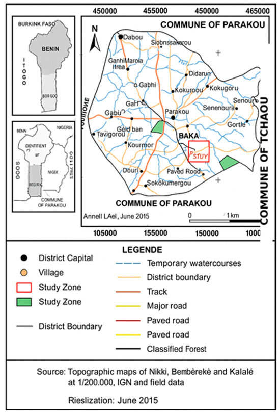
Figure 3.
Geographical location of the Baka soil sampling site.
2.1.2. Particle Size Distribution and Mineralogical Composition
Particle size and mineralogical analyses were performed to characterize the distribution of particles and the nature of mineral constituents, essential information for anticipating the mechanical and hygrothermal behavior of CEBs, as summarized in Table 1.

Table 1.
Mineralogical composition of Baka soil.
2.1.3. Tested Formulations
Four optimized formulations were selected, four optimized formulations were selected, as detailed in Table 2.
Table 2.
Composition of the different compressed earth block (CEB) formulations.
2.2. Block Manufacturing
The masonry units (29.5 × 14 × 9 cm3) were produced using a MecoPress hydraulic press (MecoConcept, Castelnaudary, France), ensuring uniform compaction. The technical specifications of the press are presented in Table 3.
Table 3.
Technical specifications of the MecoPress used for CEB production.
A photograph of the MecoPress press is shown in Figure 4.
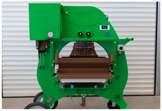
Figure 4.
Photograph of the MecoPress press used for the manufacture of CEBs.
2.3. Experimental Protocol
2.3.1. Mechanical Testing
Mechanical performance was evaluated through the following tests:
- Uniaxial compression tests, conducted in accordance with EN 772-1 (masonry units).
- Three-point bending tests, primarily following EN 1052-2 (masonry units). In specific cases, EN 1015-11 was applied, as its geometry and loading configuration are well suited to CEB specimens and allow reliable comparison with conventional masonry materials.
Before cyclic testing, the walls were stored in a climatic chamber regulated at 20 °C and 50% RH until stabilization of their mass, ensuring hygrothermal equilibrium with the storage environment. They were then placed in the bi-climatic cell, where constant temperatures of 23 °C and 15 °C were maintained on either side of the wall for 15 days. This pre-conditioning step allowed the redistribution of the initial moisture content within the specimens and ensured that a stabilized hygrothermal state was reached before the start of the experimental cycles.
For each formulation, six specimens were tested to ensure representative mean values and standard deviations.
2.3.2. Dynamic Hygrothermal Testing
Hygrothermal performance was evaluated using an instrumented bi-climatic cell specifically designed to reproduce daily temperature and humidity cycles representative of tropical humid climates. The cell consists of two independent compartments (“indoor” and “outdoor”), each measuring 30 × 60 × 50 cm and constructed from bakelized plywood insulated with 6 cm of extruded polystyrene. The compartments are separated by the test wall, which is sealed with Compriband gaskets and laterally insulated with sprayed polyurethane foam to minimize thermal and moisture bridges. The design of the bi-climatic cell is illustrated in Figure 5.
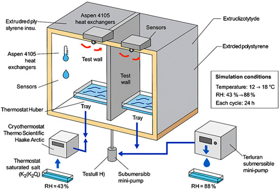
Figure 5.
Schematic diagram of the bi-climatic cell used for testing CEB walls.
Thermal regulation is ensured by Aspen 4105 heat exchangers (Aspen Systems, Marlborough, MA, USA) mounted on the ceiling of each compartment. Each exchanger is equipped with a fan that promotes air circulation and ensures uniform distribution of temperature and relative humidity. The indoor compartment is connected to a Huber thermostatic bath, maintaining a stable temperature of 23 ± 0.05 °C. The outdoor compartment is connected to a Thermo Scientific Haake Arctic cryothermostat (Thermo Scientific, Karlsruhe, Germany; −10 °C to 100 °C), enabling the simulation of daily cycles. Water circulation between the baths and the exchangers is maintained by a submersible mini-pump, ensuring a constant flow rate of 5 L/min.Relative humidity is stabilized by saturated salt solutions placed at the bottom of the compartments: potassium carbonate (K2CO3) for the indoor side (RH ≈ 43%) and potassium chloride (KCl) for the outdoor side (RH ≈ 88%). Each solution covers nearly the entire bottom surface of the compartment, ensuring effective passive regulation.
The simulated outdoor climatic cycles reproduced daily variations of 12–18 °C (temperature) and 43–88% (relative humidity). Each cycle lasted 24 h, alternating between heating–cooling and drying–humidifying phases. A total of 15 consecutive cycles (15 days) was applied for each tested wall. Temperature and relative humidity were monitored at mid-height of both compartments using calibrated sensors (accuracy ± 0.1 °C and ±2%RH) and the probe placement is illustrated in Figure 6. Calibration was performed with saturated salt solutions following Greenspan’s method, with correction for temperature dependence.
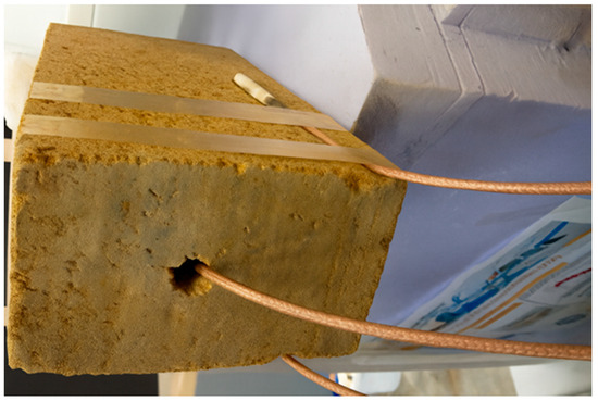
Figure 6.
Photograph of the brick with probes placed in the middle of the wall.
For each 24 h cycle, the amplitude was defined as the difference between the daily maximum and minimum of the indoor/outdoor signal after removing the first-day transient. The attenuation factor was computed as f = Aout/Ain for temperature and relative humidity. The time lag (Δt) was determined by the maximum of the cross-correlation between the outdoor and indoor signals (detrended per cycle). Reported values correspond to the average over the last 10 stable cycles (days 6–15) and are given as mean ± SD. Uncertainty on Δt reflects the standard deviation across cycles; uncertainty on f propagates the amplitude uncertainties (95% CI by bootstrap over cycles).
3. Results
3.1. Mechanical Performance
The uniaxial compression and three-point bending tests revealed marked differences between formulations. Figure 7 presents the experimental setup for the dynamic hygrothermal testing.
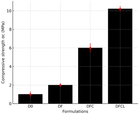
Figure 7.
Compressive strength of CEB formulations (D0, DF, DFC, DFCL). Bars show mean values; error bars represent ± one standard deviation (n = 6).
Figure 8 presents the temperature variation recorded during the test cycles.
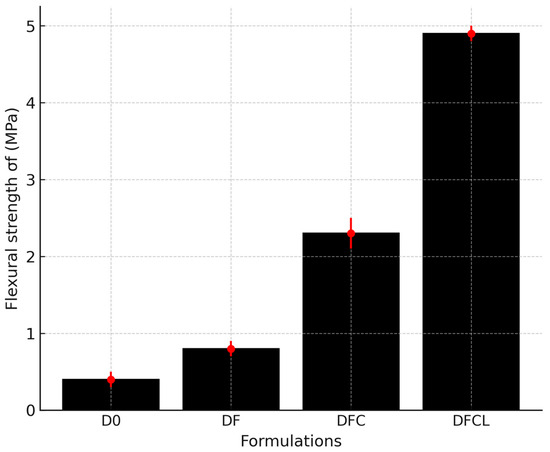
Figure 8.
Flexural strength of CEB formulations (D0, DF, DFC, DFCL). Bars show mean values; error bars represent ± one standard deviation (n = 6).
The mechanical performance of the different formulations is summarized below:
- D0 (soil only): The reference formulation exhibited moderate compressive strength, which remains insufficient for multi-story construction.
- DF (soil + fibers): The incorporation of natural fibers produced a slight improvement in strength compared to D0, with compressive strength reaching approximately 6 MPa. This enhancement can be attributed to the fiber-bridging mechanism, which helps limit crack propagation and delay failure.
- DFC (soil + fibers + cement): The addition of cement as a mineral stabilizer led to a marked increase in both compressive and flexural strength, with values exceeding the regulatory thresholds for buildings up to R + 1.
- DFCL (soil + fibers + cement + slag): This formulation achieved the best overall performance, with a compressive strength of about 10 MPa—nearly twice that of DF and improved toughness (see Figure 7 for compressive strength distribution). The combined presence of cement and slag promoted matrix densification, while fibers contributed to crack control and energy absorption.
Statistical analysis confirmed the significance of these differences: a one-way ANOVA indicated that the mechanical strength of the formulations differed significantly, F(3,20) = 15.4, p < 0.001 (see Table 4 for summarized values).
Table 4.
Summary of mechanical performance of compressed earth blocks (mean ± SD, n = 6).
Overall, the results demonstrate that combining mineral stabilization with fiber reinforcement is highly effective in optimizing the mechanical performance of compressed earth blocks. Cement and slag enhance load-bearing capacity through densification of the matrix, while fibers play a structural role in crack control, resulting in improved toughness and durability.
3.2. Dynamic Thermal Behavior
Analysis of temperature recordings (see Figure 9) shows:
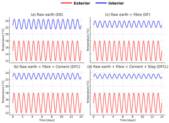
Figure 9.
Temporal evolution of temperatures at different points of the bi-climatic cell: (a) raw earth, (b) raw earth + fiber + cement, (c) raw earth + fiber, (d) raw earth + fiber + cement + slag.
- A thermal time lag for all formulations, indicating thermal inertia.
- Attenuation of indoor amplitudes compared to outdoor variations.
Performance ranking:
- DFCL and DFC: Strong attenuation of temperature peaks, moderate time lag.
- DF: Intermediate attenuation, greater time lag than stabilized formulations.
- D0: Low attenuation, limited time lag, indoor temperature close to outdoor variations.
These results are consistent with the numerical indicators of attenuation factor and time lag (summarized in Table 5), confirming the superior thermal inertia of stabilized formulations compared to fiber-only and raw soil.
Table 5.
Thermal performance indicators of the CEB walls.
Observed trend: Stabilized formulations have better attenuation but reduced time lag, while fiber-only formulations maintain more marked inertia.
3.3. Dynamic Hygroscopic Behavior
Relative humidity measurements (see Figure 10 for RH dynamics) highlight:
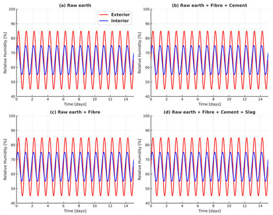
Figure 10.
Temporal evolution of relative humidity at different points of the bi-climatic cell: (a) raw earth, (b) raw earth + fiber + cement, (c) raw earth + fiber, (d) raw earth + fiber + cement + slag.
- A hygroscopic time lag between outdoor and indoor conditions.
- Attenuation of internal variations, confirming the hygroscopic capacity of CEBs.
Performance ranking:
- DFCL and DFC: High hygroscopic attenuation, linked to low water vapor permeability.
- DF: Moderate attenuation, but good balance between regulation and wall breathability.
- D0: Low attenuation, high permeability, variations close to outdoor.
Quantitatively, DFCL achieved the best performance, with a hygroscopic attenuation factor of 2.05 and a time lag Δt ≈ 1.1 h (see Table 6 for summarized values). The key observation was that stabilized formulations offer more effective hygroscopic regulation, but at the cost of reduced wall breathability.
Table 6.
Hygrothermal performance indicators of the CEB walls.
We observed that DFCL and DFC offer high hygroscopic attenuation, associated with low water vapor permeability; DF maintains a balance between regulation and breathability; and D0 shows low attenuation and high permeability.
4. Discussion
4.1. Interactions Between Mechanical and Hygrothermal Performance
The results confirm a strong interdependence between mechanical and hygrothermal properties. Formulations stabilized with cement and/or slag, combined with plant fiber reinforcement, exhibit the highest compressive and flexural strengths, exceeding the thresholds required for buildings up to R+1 (ISO 17892-7). This improvement results from the densification of the matrix by hydraulic binders, reducing porosity and increasing internal cohesion, as well as from the bridging effect of fibers, which limits crack propagation and improves toughness [11] (see Figure 7 and Figure 8 and Table 4 for detailed mechanical performance).
However, this densification reduces water vapor permeability and thus limits hygroscopic regulation. Fiber-only formulations, although less mechanically performant, maintain higher open porosity, favoring wall breathability and improving thermal comfort in naturally ventilated buildings [9,10] (see Figure 10 and Table 6 for hygroscopic performance).
4.2. Dynamic Thermal Behavior
The analysis of temperature variations shows:
A thermal time lag between the exterior and the interior for all formulations.
Attenuation of interior temperature amplitudes compared to the exterior.
In the morning, the rise in indoor temperature is delayed; in the evening, cooling is also delayed, reflecting the thermal inertia effect of CEBs (see Figure 9 for temperature profiles).
Comparatively:
D0 (soil only): Moderate time lag, low attenuation; indoor temperature closely follows external variations.
DF (soil + fibers): More marked attenuation and improved thermal inertia.
DFC and DFCL (soil + fibers + stabilizers): High attenuation but lower time lag, probably linked to higher thermal conductivity and reduced porosity.
Implication: Fiber-only formulations effectively reduce daily variations, while stabilized formulations better smooth temperature peaks but react more quickly to changes. This finding matches observations on the antagonistic density–time lag relationship [6] (see Table 5 for summarized values of Δt and f).
4.3. Dynamic Hygroscopic Behavior
Relative humidity measurements reveal:
A hygroscopic time lag between exterior and interior conditions.
Attenuation of internal variations, confirming the hygroscopic capacity of CEBs (see Figure 10 for RH dynamics).
In the humid phase, the indoor increase is delayed; in the dry phase, the moisture release is gradual, contributing to the stabilization of the indoor climate.
Comparatively:
- D0: Low attenuation, high permeability, variations close to the exterior.
- DF: Better attenuation thanks to the fibrous microstructure temporarily retaining moisture.
- DFC and DFCL: High hygroscopic attenuation, linked to low vapor permeability, but possibly causing prolonged moisture retention.
Implication: DF offers an interesting compromise for naturally ventilated buildings, while DFC and DFCL are better suited for configurations requiring stable humidity levels, provided that the risk of residual moisture is controlled (see Table 6 for summarized values).
4.4. Synthesis and Implications for Bioclimatic Design
The results highlight a formulation–use compromise:
DFC and DFCL: Suitable for buildings with high thermal inertia and limited ventilation, allowing temperature peaks to be delayed and passive comfort to be optimized (see Figure 9 and Table 5 for thermal performance; see Figure 10 and Table 6 for hygroscopic regulation).
DF: Preferable for naturally ventilated buildings, where wall breathability is essential (see Figure 10 and Table 6).
The choice of formulation must integrate the ventilation mode, structural requirements, and local climatic conditions, in line with the principles of bioclimatic design for hot and humid climates.
4.5. Research Perspectives
The perspectives include:
Long-term aging: evaluating the effect of prolonged cycles (wetting–drying, freeze–thaw) on performance [13].
Fiber optimization: type, length, and treatment, to maximize mechanical and hygroscopic effects [9].
Multi-physics modeling: combining experimental data and simulations to predict building-scale behavior [14].
Local valorization: integrating binders and fibers from agro-industrial waste to strengthen the environmental sustainability and socio-economic impact of CEBs [10].
These perspectives highlight the need to combine experimental and numerical approaches to ensure the durability and large-scale applicability of kenaf fiber-reinforced cement–slag stabilized CEBs in tropical humid climates.
5. Conclusions
This study evaluated, under controlled conditions, the mechanical and dynamic hygrothermal behavior of compressed earth block (CEB) walls subjected to climatic cycles representative of a tropical humid environment. Four formulations, with or without mineral stabilization and fiber reinforcement, were compared.
The results showed that stabilized formulations with cement and/or slag combined with plant fiber reinforcement provided the highest mechanical strengths, exceeding the regulatory thresholds for buildings up to R + 1. DFCL blocks achieved ≈10 MPa in compression and ≈5 MPa in flexion. From a thermal perspective, DFCL and DFC ensured strong attenuation of temperature variations (f up to 2.24, Δt ≈ 0.9 h), improving indoor comfort. However, detailed energy simulations would be required to quantify their exact impact on air-conditioning demand. Regarding hygroscopic performance, stabilized formulations effectively limited indoor humidity variations, while fiber-only formulations offered a better balance between regulation capacity and wall breathability (attenuation up to 2.05; Δt ≈ 1.1 h).
This work provides: (i) an experimental demonstration, in a bi-climatic cell, of the combined impact of mineral stabilization and fiber reinforcement on mechanical and hygrothermal performances; (ii) an integrated analysis of thermal and hygroscopic performance, rarely addressed jointly in the literature; and (iii) the identification of formulation–use compromises, useful for bioclimatic design in tropical humid climates. Together, these findings reinforce the potential of kenaf fiber-reinforced cement–slag stabilized CEBs as a sustainable construction solution for hot and humid regions.
Perspectives
We propose the following future research directions:
- Valuate the long-term hygrothermal aging of CEBs in real conditions.
- Develop multi-physics numerical models integrating experimental data to predict behavior at the building scale.
- Explore the use of fibers and binders from local agro-industrial waste to reinforce the eco-responsible and socio-economic dimension of CEBs.
In conclusion, the DFCL blocks combined high mechanical strength (σc ≈ 10 MPa) with superior hygrothermal regulation (thermal attenuation factor 2.24, hygroscopic attenuation factor 2.05, with time lags of ~0.9 h and ~1.1 h, respectively). These findings demonstrate their potential for sustainable construction in tropical humid climates, particularly for load-bearing walls up to R + 1. Beyond technical performance, DFCL also offers environmental and economic advantages, since the use of local fibers and slag reduces Portland cement consumption and costs, reinforcing their sustainability potential in tropical contexts.
Author Contributions
Conceptualization, A.B.L. and P.P.; Methodology, A.B.L., P.P. and N.L.; Software, A.B.L.; Validation, P.P., N.L., and M.G.; Formal Analysis, A.B.L.; Investigation, A.B.L.; Resources, P.P. and M.G.; Data Curation, A.B.L.; Writing—Original Draft Preparation, A.B.L.; Writing—Review and Editing, P.P., N.L., and M.G.; Visualization, A.B.L.; Supervision, P.P. and N.L.; Project Administration, P.P.; Funding Acquisition, P.P. and M.G. All authors have read and agreed to the published version of the manuscript.
Funding
This research was funded by the Service for Cooperation and Cultural Action (SCAC) of the French Embassy in Benin. The work was carried out at the GeM laboratory in Saint-Nazaire, France.
Data Availability Statement
The data presented in this study are available upon request from the corresponding author.
Acknowledgments
The authors would like to thank Ahmed Loukili (GeM UMR CNRS 6183) and Ouali Amiri (GeM for the Saint-Nazaire site) for their welcome and logistical support at the laboratory.
Conflicts of Interest
The authors declare no conflicts of interest.
References
- Bailly, G.C.; El Mendili, Y.; Konin, A.; Khoury, E. Advancing Earth-Based Construction: A Comprehensive Review of Stabilization and Reinforcement Techniques for Adobe and Compressed Earth Blocks. Eng 2024, 5, 750–783. [Google Scholar] [CrossRef]
- Hall, M.; Allinson, D. Analysis of the Hygrothermal Functional Properties of Stabilised Rammed Earth Materials. Build. Environ. 2009, 44, 1935–1942. [Google Scholar] [CrossRef]
- Little, B.; Morton, T. Building with Earth in Scotland: Innovative Design and Sustainability; Scottish Executive Central Research Unit: Edinburgh, UK, 2001. [Google Scholar]
- Hagentoft, C.-E. Introduction to Building Physics; Studentlitteratur: Lund, Sweden, 2001. [Google Scholar]
- Künzel, H.M. Simultaneous Heat and Moisture Transport in Building Components; Fraunhofer IRB Verlag: Stuttgart, Germany, 1995. [Google Scholar]
- Chraibi, H.; El Abbassi, F.-E.; Sakami, S.; Bouferra, R.; Kchikach, A. Thermal Improvement of Compressed Earth Blocks by Using Liquid and Solid Olive Oil Wastes in the Region of Marrakesh, Morocco. Euro-Mediterr. J. Environ. Integr. 2023, 8, 935–948. [Google Scholar] [CrossRef]
- Chehade, S.; Sidiboulenouar, R.; Dujardin, N.; Maillet, B.; Mertz, J.-D.; Giovannacci, D.; Keita, E.; Melinge, Y.; Boudenne, A. Experimental Investigation of Hygrothermal Properties of Raw Earth Compressed Blocks. In RILEM Bookseries; Springer: Cham, Switzerland, 2024; pp. 715–728. [Google Scholar] [CrossRef]
- Touré, P.M.; Sambou, V.; Faye, M.; Thiam, A.; Adj, M.; Azilinon, D. Mechanical and Hygrothermal Properties of Compressed Stabilized Earth Bricks (CSEB). J. Build. Eng. 2017, 13, 266–271. [Google Scholar] [CrossRef]
- Kenmogne, F.; Foadieng, E.; Tiokeng, O.L.; Eno, R.; Ngnihamye, M.N.; Tchoukouabe, A.; Wafo Wafo, S.H.; Sali, M.; Yamb Bell, E.; Nguiya, S. Physico-Mechanical Characterization of Compressed Earth Blocks Reinforced with Waste Fibers from Calamus rotang: Case of Elastic Soil of Western Region of Cameroon. Mater. Technol. Rep. 2024, 2, 1650. [Google Scholar] [CrossRef]
- Lbakhkhouch, H.; Nasla, S.; Laatar, M.; Kheltent, M.; Gueraoui, K.; Cherraj, M. Enhancement of Mechanical and Thermal Qualities in Compressed Earth Blocks (CEBs) Reinforced with Coconut Fibers. JP J. Heat Mass Transf. 2024, 37, 143–157. [Google Scholar] [CrossRef]
- Sidiki, A.; Chantit, F. Physical, Mechanical, and Durability Properties of Compressed Earth Blocks Filled by Juncus Plant Fibers. Int. J. Innov. Appl. Stud. 2024, 42, 194–205. Available online: http://www.ijias.issr-journals.org/abstract.php?article=IJIAS-24-004-09 (accessed on 19 September 2025).
- Ashour, T.; Wieland, H.; Georg, H.; Bockisch, F.-J.; Wu, W. The Influence of Natural Reinforcement Fibres on Insulation Values of Earth Plaster for Straw Bale Buildings. Mater. Des. 2010, 31, 4676–4685. [Google Scholar] [CrossRef]
- Abdallah, R.; Carré, H.; McGregor, F. Effect of Compaction Pressure on the Risk of Thermal Instability of Compressed Earth Bricks. Mater. Struct. 2024, 57, 84. [Google Scholar] [CrossRef]
- Hany, E.; Fouad, N.; Abdel-Wahab, M.; Sadek, E.; Mahmoud, S. Simulating the Thermal Behavior of Compressed Earth Brick Walls. Int. J. Concr. Struct. Mater. 2025, 19, 27. [Google Scholar] [CrossRef]
Disclaimer/Publisher’s Note: The statements, opinions and data contained in all publications are solely those of the individual author(s) and contributor(s) and not of MDPI and/or the editor(s). MDPI and/or the editor(s) disclaim responsibility for any injury to people or property resulting from any ideas, methods, instructions or products referred to in the content. |
© 2025 by the authors. Licensee MDPI, Basel, Switzerland. This article is an open access article distributed under the terms and conditions of the Creative Commons Attribution (CC BY) license (https://creativecommons.org/licenses/by/4.0/).