1. Introduction
Earth construction plays a vital role as a sustainable housing solution worldwide, offering remarkable versatility through a wide range of techniques and creative approaches developed across different regions. The economic feasibility of this construction method depends on several factors, including the construction process, structural durability, maintenance requirements, material stabilization, and labor availability [
1]. Among the various earth-based construction systems, commonly employed techniques include adobe brick masonry, rammed earth, cob, wattle and daub, and poured earth [
2]. In the southwestern region of Colombia, bahareque construction is widely used by local communities for diverse purposes, including residential buildings and schools. Bahareque is a traditional building system characterized by a structural framework of wood and/or guadua (a bamboo-like material), filled with an earthen mixture and finished with a coating, which often includes a blend of soil and cagajón (a locally sourced organic additive) [
3]. It is worth noting that cagajon can be substituted with finer soil or other materials.
Previous studies have highlighted the economic advantages of bahareque construction. Palacios and Angumba [
4] estimated the cost of a 130 m
2 bahareque house in Cuenca, Ecuador, at USD 36,387, demonstrating a significant cost advantage compared to conventional housing in the region. Similarly, Tello-Ayala et al. [
5] conducted a life-cycle cost analysis comparing a two-story social housing unit built with bahareque to one constructed with reinforced concrete. Their results indicated a 40% reduction in total cost and a 50% reduction in construction time for the bahareque alternative. From an environmental performance, bahareque construction was shown to generate only 27% of the embodied carbon emissions associated with reinforced concrete housing. Despite these benefits, further research is needed to deepen the understanding of bahareque construction methods and structural performance to promote its broad adoption as a sustainable and resilient building technology, particularly in seismic-prone areas.
Understanding the seismic performance of earth construction in earthquake-prone regions is a critical global concern. Risk assessment and structural reinforcement have emerged as major research trends in this field, as noted by Sánchez-Calvillo et al. [
6]. To evaluate the seismic behavior of earthen structures, several pseudo-static tests have been carried out on different wall systems. Vieux-Champagne et al. [
7] tested one- and two-story timber-framed walls with stone and earth infill, reporting that failure typically occurred at the connections when a 3% drift level was reached. Zhou et al. [
8] compared the seismic performance of one-story adobe walls built with different types of bricks, concluding that the inclusion of core columns is essential for maintaining structural stability. Ruiz et al. [
9] performed full-scale testing on a two-story rammed earth wall, demonstrating the effectiveness of a steel plate retrofitting system that meets architectural requirements while ensuring long-term durability due to its non-biodegradable nature. In Colombia, two notable studies have addressed the seismic performance of bahareque wall systems. Herrera and Takeuchi [
10] conducted full-scale pseudo-static tests on two-story Guadua angustifolia frames with precast bahareque panels, underscoring the critical importance of connection detailing in ensuring structural integrity. Cristancho et al. [
11] performed in-plane pseudo-static tests on one-story bahareque walls and found that employing a wooden frame increased lateral strength by 23% compared to a guadua-based structural frame. Collectively, these experimental investigations highlight the need for continued research aimed at enhancing the seismic resilience of earth construction systems and developing innovative reinforcement strategies that are both effective and compatible with local construction practices and materials.
From a structural design standpoint, numerical modeling techniques are essential for the analysis and design of earth buildings, particularly through finite element method (FEM)-based software. Several studies have examined the seismic performance of bahareque-like wall systems using numerical simulations. Quinn et al. [
12] developed a numerical model of historic Quincha walls that incorporated vertical uplift effects, semi-rigid rotational connections, and shell elements for the infill. Their results showed discrepancies of up to 20% when compared with experimental cyclic test data. Parisse et al. [
13] proposed an OpenSees-based FEM model for Romanian timber-framed masonry walls, employing an equivalent timber frame representation, a lumped plasticity approach, and spring-based elements to simulate the joint behavior. Jiménez and Pelá [
14] applied a macro-mechanical FEM approach combined with lumped plasticity to evaluate the seismic performance of infilled Quincha frames, implementing the equivalent strut method to capture the nonlinear behavior of the infill. Mite-Anastacio [
15] investigated the structural response of cement-stabilized bahareque houses in Guayaquil (Ecuador) using a simplified FEM model that incorporated frame elements for guadua, idealized connection behavior, and shell elements for the floor slabs. The study highlighted the challenge of accurately replicating real-world construction details and material variability in numerical simulations. The above works demonstrate that each earth construction technique possesses unique structural characteristics, requiring tailored finite element modeling strategies to achieve accurate and reliable structural performance assessments under seismic loading.
This study proposes a finite element-based methodology for modeling the structural response of Bahareque walls built in Colombia under cyclic loading. Calibration data were obtained from pseudo-static seismic tests on Bahareque walls reported in reference [
11], considering both wood and guadua frames. The modeling process began with unfilled conditions to isolate the frame behavior, after which two additional tests were incorporated to account for the influence of the soil infill. Accordingly,
Section 2 describes the in-plane pseudo-static tests conducted on five specimens. The numerical model incorporates key construction characteristics, including the potential loss of structural element connections. Ansys 2022 R1 was selected for FEM modeling, as it has been successfully used in previous earth construction studies [
16,
17,
18].
2. General Description of Pseudo-Static Test of Bahareque Walls
The Valle del Cauca department, located in southern Colombia, is highly susceptible to seismic activity due to its proximity to the Nazca Plate subduction zone and the presence of active crustal faults [
19]. In this region, bahareque is commonly used for housing, particularly in rural communities, because of the abundance and accessibility of local construction materials.
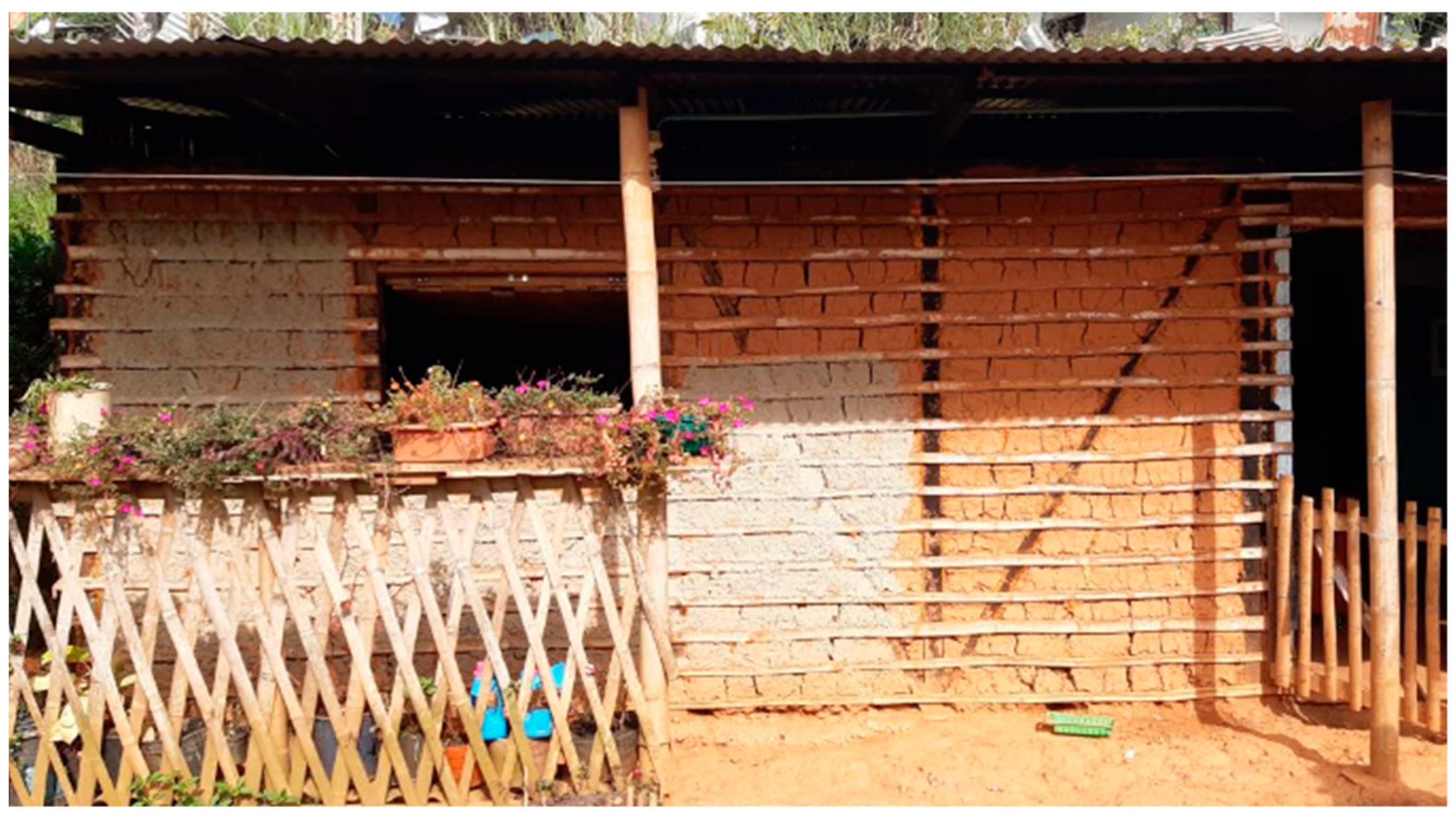
Figure 1 illustrates a bahareque house located in the Estrella Community, Jamundí, which incorporates a lighthouse-type structural configuration. Despite its widespread application, research on the seismic performance of bahareque buildings in Colombia remains limited. Advancing research in this area could foster significant improvements in self-construction practices and support the development of more earthquake-resistant rural housing. Notably, several institutions have already developed preliminary guidelines for supporting the seismic-resistant design and construction of bahareque structures [
3,
20,
21].
Cristancho et al. [
11] conducted in-plane pseudo-static tests on bahareque walls at the Pontificia Universidad Javeriana’s Structural Engineering Laboratory, with researchers from both Cali and Bogotá campuses collaborating on the project. This study reflects the university’s commitment to advancing knowledge on the seismic performance of informal structures, in a country where more than 80% of the population lives in earthquake-prone regions. Five bahareque wall specimens were tested, as shown in
Figure 2, each with a height of 2.2 m and a width of 2.2 m. The first specimen corresponded to a bare guadua frame, while the second and third included horizontal strips and were built with wood and guadua, respectively. The fourth and fifth specimens incorporated soil infill within the wood and guadua frames. The infill, applied in accordance with standard construction practices in Colombia, consisted of silt mixed with sand and a native natural fiber (
Andropogon glomeratus, Poaceae family), with an average thickness of 5 cm. For the connections, 3-inch steel nails were used to join the wall elements, a factor that may play a critical role in ensuring adequate seismic performance.
Figure 3 illustrates the pseudo-static test setup for bahareque walls. A servo-controlled MTS hydraulic actuator (MTS Systems, 14000 Technology Dr, Eden Prairie, MN, USA), mounted on a reaction wall, applied cyclic horizontal displacement at the top of specimens. A rolling mechanism, supported by a reaction steel frame, ensured in-plane motion. The actuator was connected to the bahareque walls through two steel plates linked by four rods, allowing reversible displacement. A steel beam placed on top simulated roof loads, applying a total vertical load of 1.9 kN. The foundation consisted of a concrete beam designed to replicate stone or cyclopean concrete foundations commonly found in the field. This foundation beam was anchored to the strong floor of the structure’s laboratory. For additional details on test procedures, material characterization, construction considerations, experimental results, and failure mechanisms, refer to [
11]. Future research will focus on full-scale house models that incorporate out-of-plane behavior and the dynamic effects of earthquakes.
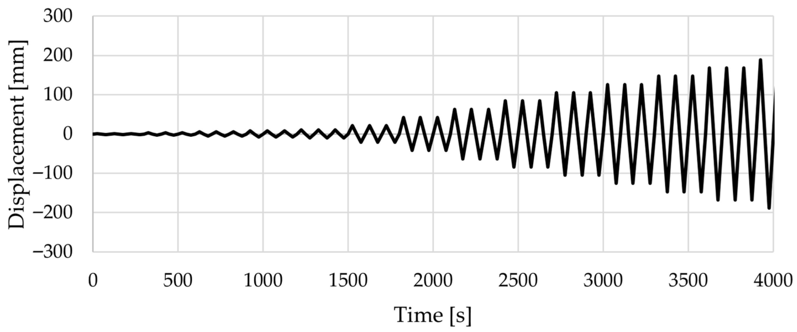
The cyclic displacement protocol was designed with incremental displacements applied at the top of the walls, using three cycles per increment, up to a maximum displacement corresponding to a 6.0% drift relative to the height of the bahareque wall.
Figure 4 presents the final protocol for all specimens, which was terminated once failure occurred. Similar protocols can be found in references such as [
22].
Instrumentation consisted of a total of seven LVDT sensors (OMEGA Engineering, Stamford, CT, USA) to measure horizontal and vertical displacements at strategic points on the walls, as shown in
Figure 5. Three horizontal sensors were placed at the base, mid-height, and top of the central vertical axis of the wall to record lateral displacements, while four sensors were used to measure vertical uplift between the base element and the vertical side elements. The horizontal sensor at the base was installed to verify any relative movement between the wall and the foundation. During testing, it was necessary to remove some sensors once the allowable displacement was nearly reached. In addition, the hydraulic actuator was instrumented with a 250 mm-range LVDT sensor to verify that the displacement protocol was applied correctly, and it was also equipped with a load cell to measure the horizontal load applied to the wall specimens.
3. Finite Element Modeling
An equivalent 2D pseudo-static model was applied to simulate the structural behavior of a bahareque wall subjected to the cyclic loading protocol presented in
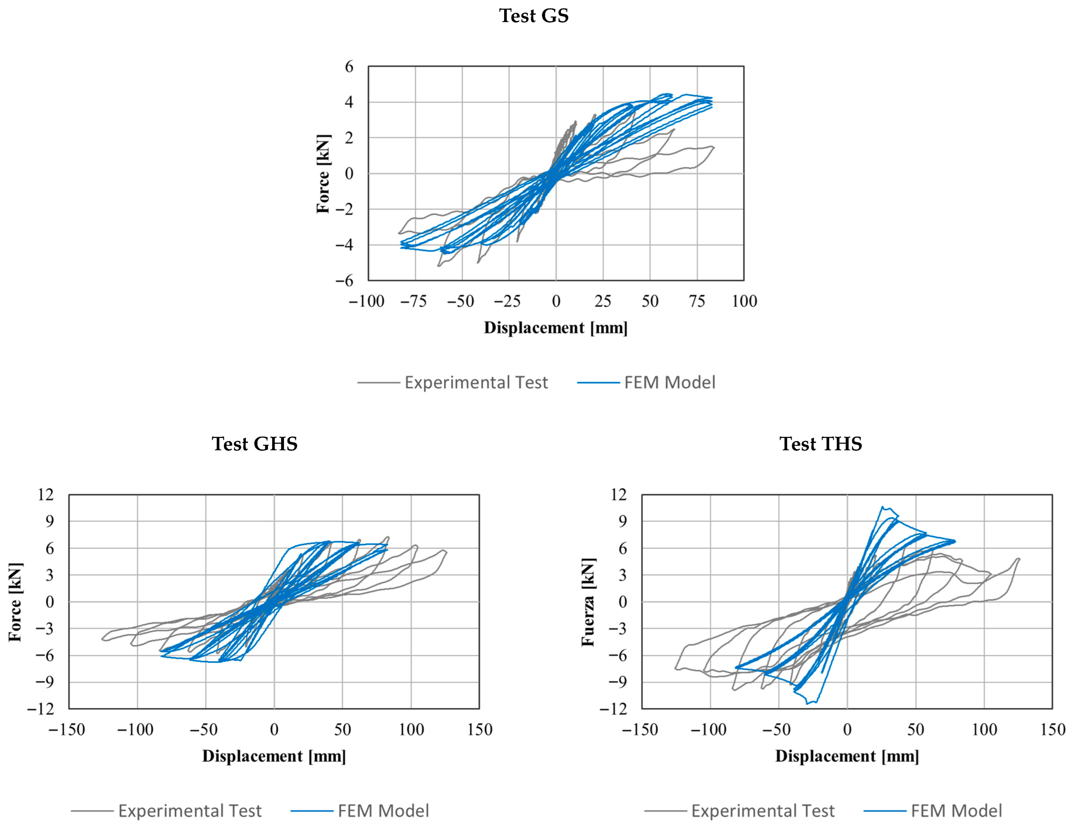
Figure 4. Two different groups of models were developed to consider the presence or absence of the infill soil. Such a division eases the understanding of the isolated behavior of the wood/guadua frame under the cycling loading. In the first group, the development of the finite element model initially uses the results from the test of the specimen GS to consider exclusively the guadua bare frame, as observed in
Section 3.1. Then, the obtained model was verified from the other two tests on bare frames with horizontal guadua strips (GSH and TSH).
Table 1 presents the mechanical properties of guadua and wood material, using the works by Cristancho [
23] and Ayala [
24]. For the model considering the infill soil, the effect of the stiffness and mass of the infill soil was introduced using springs and a lumped mass located at the center of mass of each earth panel, as presented in
Section 3.2. The simulations were performed using ANSYS 2022 R1
® software. A 3D model was developed, restraining the transversal degree of freedom to capture the main in-plane wall movement. For both model groups, the frame components were simulated using beam-type line elements. Three pinned supports were assigned to the nodes at the base of the frame.
The pseudo-static load was applied at the top-left node for each model. Considering the experimental test carried out in this work, it was observed that the joints exhibited failure behavior, characterized by the separation of connection nails. Therefore, to simulate the joints, short elements were modeled using an orthotropic material with a progressive damage model based on the Puck criterion for composites, as can be seen in
Table 2. The Puck failure criterion is a failure model used for reinforced materials. The criterion considers fiber failure due to longitudinal loads and matrix failure mode due to transverse loads separately (ANSYS Help 2024 [
25]). In this work, Puck’s criterion was used as the damage initiation criterion. The damage initiation criteria were defined by means of compressive and tensile failure modes of the fiber and the matrix, using Puck’s constants as defined in
Table 1. The damage evolution law involves stiffness reduction for fibers and matrix under both tensile and compressive loading, as defined in
Table 2. More information about the damage evolution law and failure criteria can be found in the work of Pai et al. [
26] and ANSYS HELP 2024 R2.
The connection elements are used in the upper part of the structure, as the bottom part is constrained by pinned supports. The material properties for the connection elements were simulated considering the experimental results and are shown in
Table 3. A mesh convergence analysis was conducted. The non-linear analysis was carried out using the default options of Ansys for the non-linear analysis. But it was necessary to modify using a number of steps of 2720 in the full Newton–Raphson, which can change to the modified Newton–Raphson with a convergence criterion referred to the norm of the unbalanced force less than 5 × 10
−3 times the norm of the reference force (ANSYS Help 2024 [
24]).
3.1. Numerical Model: Bahareque Wall Without Soil Infill
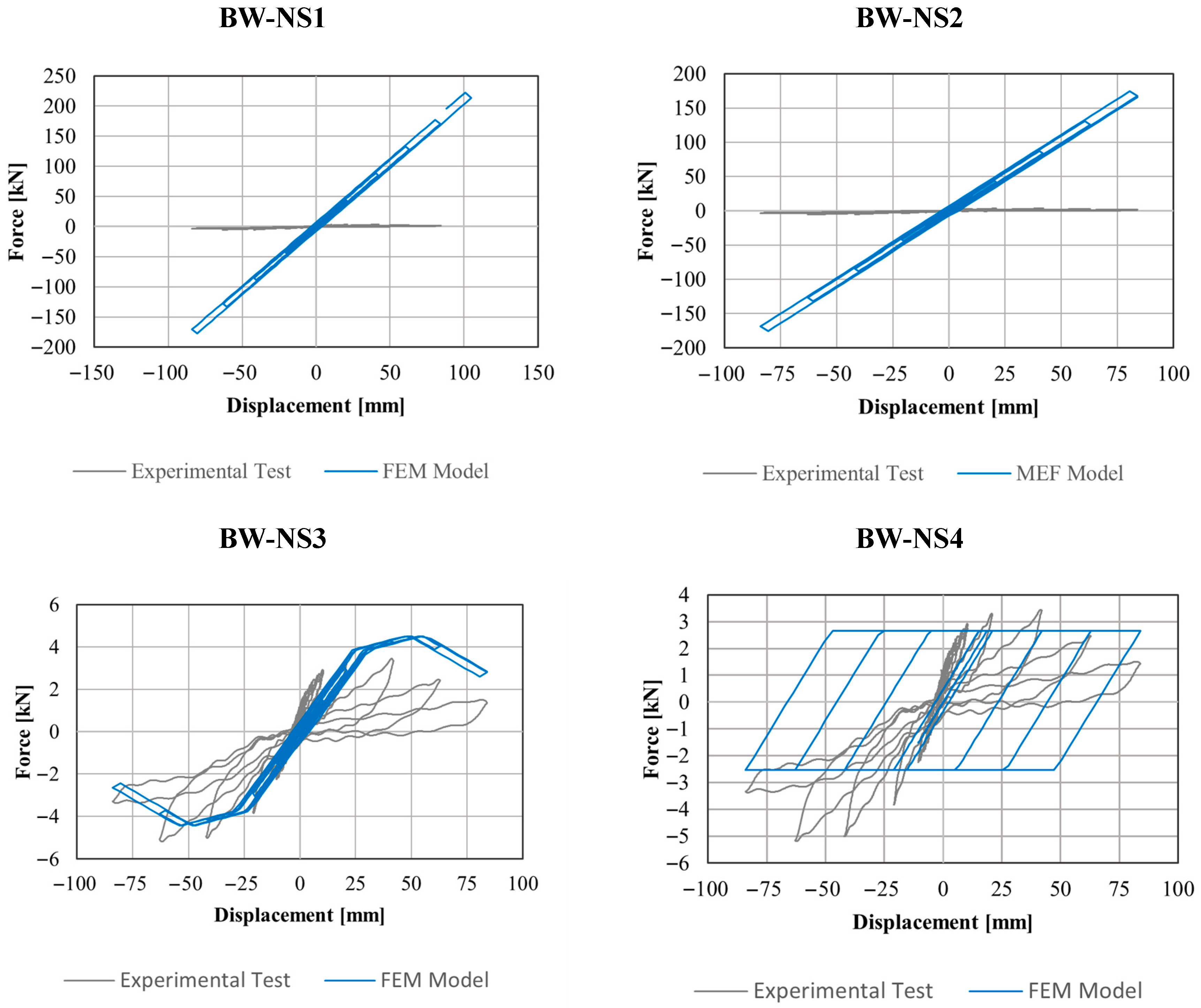
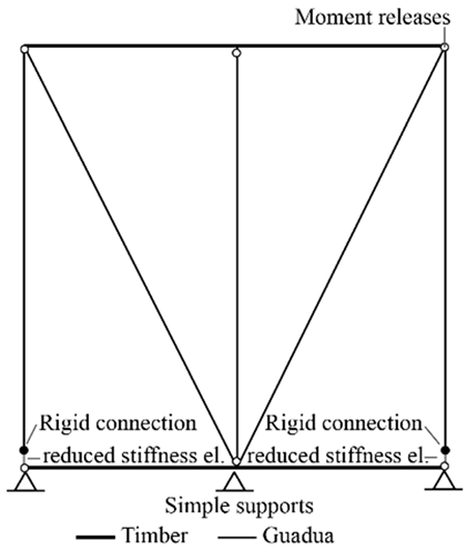
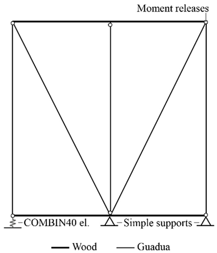
Table 4 presents four preliminary different finite element model approaches tested for bahareque walls without soil infill, with increasing complexity. This progression was necessary to understand the structural behavior of the walls by introducing small variations in the components of the numerical model. Calibration against experimental results required the development of numerical strategies to simulate the damping observed in the walls during cyclic loading. All models assumed that the horizontal structural element at the base exhibited no horizontal movement, as confirmed by the experimental tests.
The first approach (BW-NS1) employed classical modeling of the structural elements using a linear-elastic frame-type representation, with the connections modeled as perfect hinges. The second approach (BW-NS2) introduced reduced stiffness at the base of the lateral columns, set at 75% of the full stiffness of guadua bamboo elements. This was intended as a simple consideration of potential nonlinear behavior in the structural elements, effectively penalizing the linear material properties in a manner similar to certain normative design procedures. The third approach (BW-NS3) incorporated nonlinear springs at the supports to account for possible uplift in the wall, with their mechanical characteristics calibrated against experimental behavior. Finally, the fourth approach (BW-NS4) applied the COMBIN40 element as an alternative means of simulating uplift while enhancing the damping capacity of the walls, with properties calibrated to replicate the experimental results. It is worth noting that two additional models were also tested, employing nonlinear segments in the vertical elements and attempting calibration through multi-hardening material properties in ANSYS; however, the results were not satisfactory.
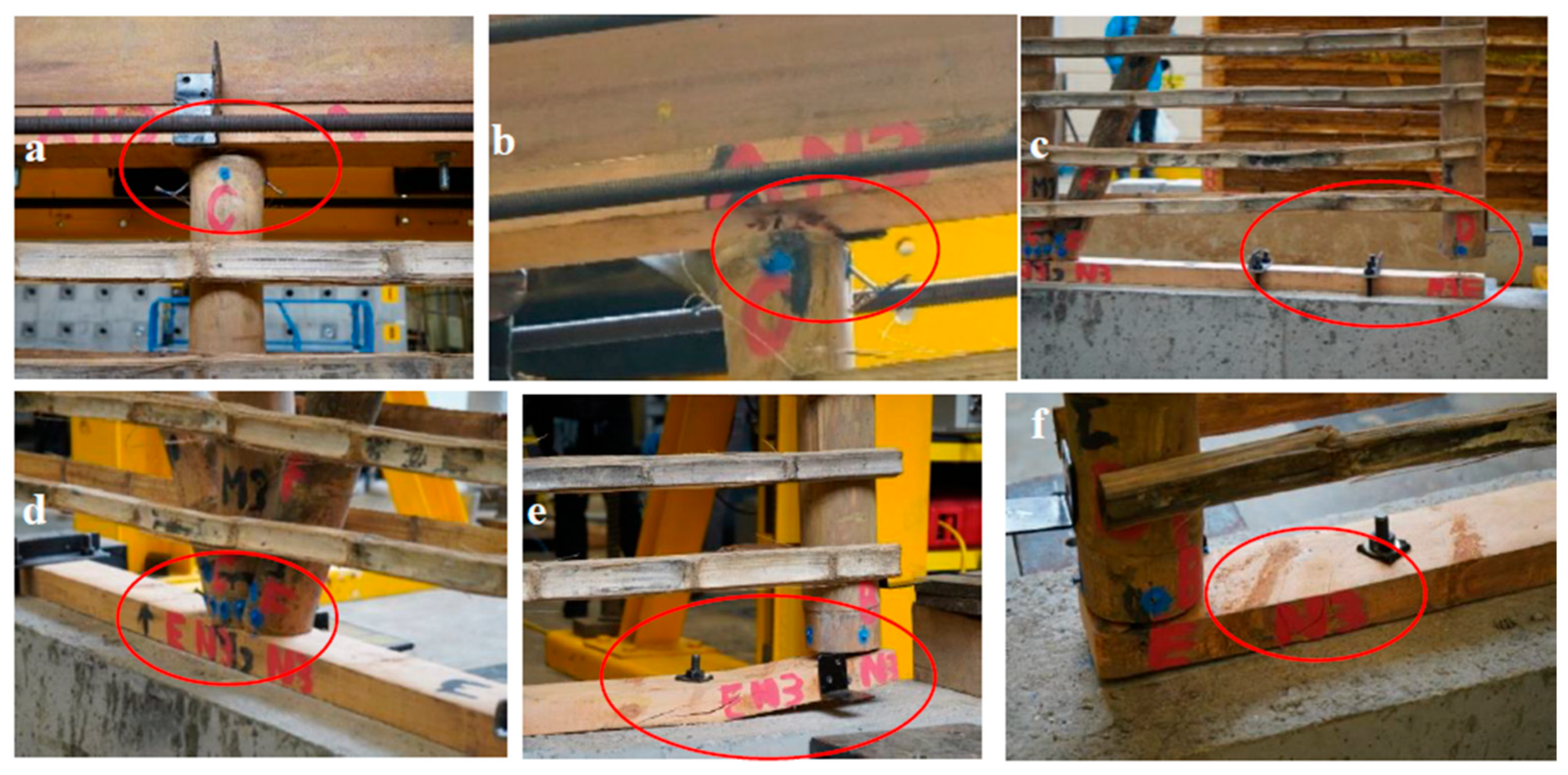
For further clarity,
Figure 6 illustrates the behavior of the walls without soil infill (GS, GSH, and TSH) during and after loading, showing various types of damage, including the failure of wooden elements.
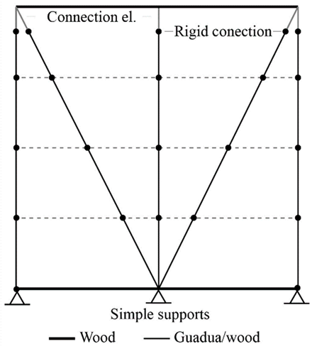
Finally, a model with non-linear elements and damage-controlled properties was implemented using the Puck failure model (BW-NS4), as introduced at the beginning of
Section 3. This strategy was adopted because the models in
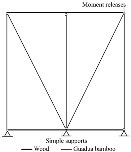
Table 2 lacked a mechanism to capture the degradation observed experimentally at the connections. In this context, an analogy can be drawn with a composite material, where the matrix is represented by the wood and the fiber by the nail.
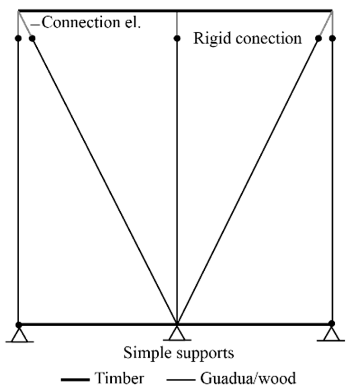
Figure 7 illustrates the configuration of this model, which incorporates non-linear elements in the diagonal members, rigid connections at key joints, and simple supports at the base. Different line styles were used to distinguish between wood and guadua/wood elements. This modeling approach was ultimately selected because of its improved ability to replicate the structural response of bahareque walls under seismic loading. It is also worth noting that this model accounts for the potential occurrence of uplift at the base of the walls.
3.2. Numerical Model: Bahareque Wall with Soil Infill
Using the final model summarized in the previous approaches, it was necessary to incorporate the soil infill into the numerical simulation.
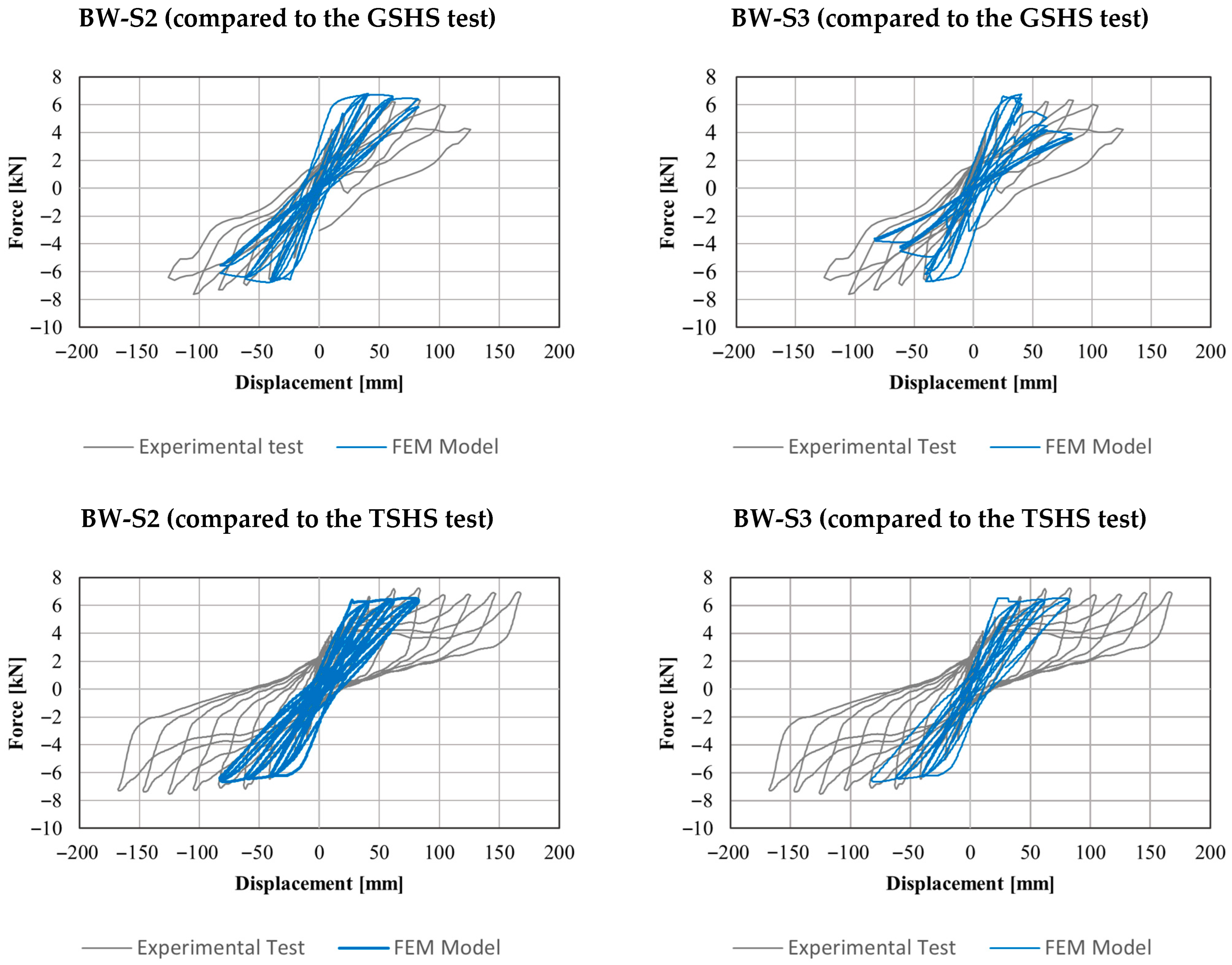
Table 5 presents three different finite element method (FEM) modeling strategies developed to represent the interaction between the soil infill and the bahareque wall structure. The maximum dry density was assumed to be 14.1 kN/m
3, and the wall thickness was set at 5 cm. In this exploratory stage, the contribution of the infilled soil to the seismic performance of the bahareque wall was simplified under the hypothesis that the structural behavior is primarily governed by the mechanical response of the connections and the interaction region between soil and structure. Accordingly, a preliminary calibration of the stiffness in the equivalent spring and lumped mass model was considered sufficient.
The first approach (BW-S1) introduces area elements between the vertical and inclined members to simulate the interaction of the soil infill with the structure, providing a more continuous representation of its contribution to the overall structural behavior. Nonlinear elements are assigned to the diagonal members, while rigid connections are implemented at key joints. The second approach (BW-S2) represents the soil infill effect using three horizontal elements connecting the vertical and inclined components, thereby allowing a layered distribution of the soil’s influence along the wall height. Rigid connections ensure that the structural response properly reflects the contribution of the soil infill in a distributed manner. The third approach (BW-S3) replaces area and horizontal elements with spring elements at the junctions between vertical and inclined members, simulating the interaction forces between the structure and the soil infill. This approach enables a more localized representation of soil behavior, capturing potential differential movements and nonlinear interactions. Each of these approaches provides a distinct perspective on soil–structure interaction in bahareque construction, contributing to the refinement of numerical simulations and improving the understanding of seismic performance.
Figure 8 shows the damage observed in the infilled walls (GSHS and TSHS), highlighting the interaction between the infill and the bare frame, as well as the loss of material.
5. Conclusions
This research represents a first attempt to develop finite element models for the pseudo-static behavior of Colombian bahareque walls, based on experimental results from previous studies. Several preliminary modeling approaches were explored to improve understanding of the complex response of bahareque walls subjected to cyclic loading. The Puck failure criterion proved effective in capturing the damage processes within the structural frame. The models were able to simulate the detailed behavior of walls with and without infill during the initial loading cycles, with errors below 12% in stiffness and 10% in peak force. Spring-based models also showed the ability to reasonably represent soil–structure interaction in infilled wall systems. However, accurately reproducing degradation at higher drift levels remains a challenge. As the number of loading cycles increases, the models fail to effectively replicate degradation phenomena, primarily due to the complexity of energy dissipation mechanisms—such as the progressive disconnection and reconnection of nailed joints—which are difficult to quantify and model with precision. This highlights the need to account for uncertainties associated with finite element models during the structural design stage.
Future research should focus on a more detailed characterization of energy dissipation sources, explicitly considering actual earthquake ground motions and spatial wall interactions. For example, bi-directional shaking table tests on full-scale houses are necessary to better capture the global structural response. To represent progressive uplift, future simulations could incorporate contact elements at the foundation interface, which would require experimental measurements of vertical displacements for proper validation. Likewise, the behavior of connections, including nail withdrawal, could be more accurately modeled using nonlinear springs calibrated with hysteretic curves obtained from either pull-out tests or high-fidelity simulations. Regarding infill cracking, a promising approach would be to adopt a material damage model capable of simulating stiffness degradation as cracks propagate. Experimental validation of this strategy would greatly benefit from the use of Digital Image Correlation (DIC), allowing precise tracking of damage evolution during testing.
