Article

Three-Dimensional Numerical Simulation for Mechanical Performance of Semi-Prefabricated Second Lining of Highway Tunnels

1
Road and Bridge International Corp., Ltd., Beijing 100010, China
2
School of Civil Engineering, Chongqing University, Chongqing 400045, China
*
Author to whom correspondence should be addressed.
Buildings 2025, 15(18), 3425; https://doi.org/10.3390/buildings15183425
Submission received: 17 August 2025 / Revised: 12 September 2025 / Accepted: 19 September 2025 / Published: 22 September 2025
(This article belongs to the Section Building Structures)

Abstract

To align with the development trends of green construction and industrialized building, prefabricated assembly technology has been widely applied in highway tunnel lining structures. However, when used in large-section highway tunnels, this technology faces challenges not only due to the large size of the components but due to the high demands in the working space. In response to the limitations of traditional assembly methods, this paper proposes a semi-prefabricated secondary lining structure for highway tunnels. The mechanical performance of the second lining constructed by various segmentation schemes under surrounding rock pressure is analyzed using a 3D shell-spring finite element model, considering both the continuous and staggered seam layouts. This study provides technical support for the design of assembled secondary lining structures in large-section highway tunnels.

1. Introduction

With the rapid development of China’s economy and population migration, the volume of passenger and freight transportation on highways has been continuously increasing. To meet traffic demands, large-section highway tunnels have become the development trend of modern expressway tunnels [1]. Fully prefabricated tunnel construction technology, due to its high degree of mechanization, guaranteed quality and progress, and favorable working environment [2], has been widely applied in shield-driven metro tunnel construction. However, because of the large size of the prefabricated components, high space requirements for operations, lifting difficulties, and the need for supporting shield machines for excavation, its application in highway tunnels still faces many challenges. Compared with the conventional cast-in-place method, the prefabricated secondary lining structure, though involving higher economic costs, can greatly improve the construction efficiency and reduce the number of on-site workers. In China, where construction labor is becoming increasingly scarce, the labor-saving advantage of this structure is becoming more and more important. Highway tunnels differ from shield tunnels in terms of cross-sectional forms, construction methods, and project costs, making the full-prefabrication approach subject to numerous critical issues that remain to be resolved.
In recent years, domestic scholars have conducted systematic research on prefabrication technology for underground structures, achieving fruitful results. In the field of fully prefabricated technology, Huang [3] used a beam–nonlinear spring model to study the segmental lining of shield tunnels with a general prefabricated assembly, and calculated the maximum internal forces and deformations of the cross-section. Xiao and Li [4], taking a dual-lane expressway shield tunnel as an example, investigated the extreme values of internal forces and deformations in the design of large-section shield tunnel segments. Zeng and He [5] studied the influence of two assembly methods—continuous joints and staggered joints—on the deformation and internal forces of shield tunnel linings. In the field of semi-prefabricated technology, Feng et al. [6] investigated the seismic performance of semi-prefabricated underground station joints, while Jiang [7] conducted quasi-static tests on semi-prefabricated column structures and analyzed the failure modes of the specimens. Conforti et al. [8], Yu et al. [9], and Zhang et al. [10] conducted experimental studies comparing the structural performance of conventional reinforcement, reinforced concrete, and hybrid fiber reinforcement. The results showed that combining hybrid fibers with conventional reinforcement can effectively sustain loads, theoretically verifying the rationality and feasibility of adopting fiber reinforcement in shield tunnel segments. N.-A. Do et al. [11] studied the influence of the number of joints and joint angles on the internal forces of the lining by establishing a planar finite element model. The results indicated that the bending moment of the lining decreases as the number of joints increases. A.M. Talmon et al. [12], based on the Shanghai Yangtze River shield tunnel, proposed a one-dimensional beam action model to calculate the longitudinal bending and shear behavior of the lining structure. Zhang et al. [13] investigated the bending capacity of joints through full-scale model tests and suggested that joint failure can be considered to occur when the vertical displacement reaches the partial slip stage.
At present, the research on prefabrication technology for underground structures mainly focuses on fully prefabricated systems. However, there has been no engineering practice involving the application of composite semi-prefabricated technology in preassembled linings for highway tunnels. Therefore, studying the use of prefabricated composite linings in semi-prefabricated highway tunnels is of great significance for promoting the development of highway tunnel support structure systems.
This paper takes a highway tunnel project in Chongqing as a case study to investigate the composite prefabricated secondary lining structure of a large-section highway tunnel. By using finite element simulations of secondary lining models with different bolt stiffness values, this study analyzes the mechanical behavior and deformation of the composite assembled tunnel lining with an invert under Class V surrounding rock conditions. The finite element analysis of models with various parameters provides reference data for the structural design of composite secondary linings in highway tunnels.

2. Highway Tunnels and Geological Conditions

The tunnel is a bidirectional four-lane highway tunnel located in a section with deep-buried Class V surrounding rock. The architectural clearance of the main tunnel has a net width of 10.25 m and a net height of 5.0 m. The tunnel cross-section, shown in Figure 1, has a horseshoe-shaped profile composed of a three-centered arch. The arch crown and the upper part of the sidewalls form concentric arcs with a radius of 555 cm, while the lower parts of the sidewalls consist of two non-concentric arcs with a radius of 850 cm. The tunnel is constructed using the New Austrian Tunneling Method (NATM); therefore, a composite lining is adopted. Since the primary lining in the composite structure can bear a certain amount of surrounding rock pressure, its support effect is taken into account when calculating the surrounding rock pressure shared by the secondary lining in this study.

2.1. The Semi-Prefabricated Second Lining and Its Segmentation Schemes

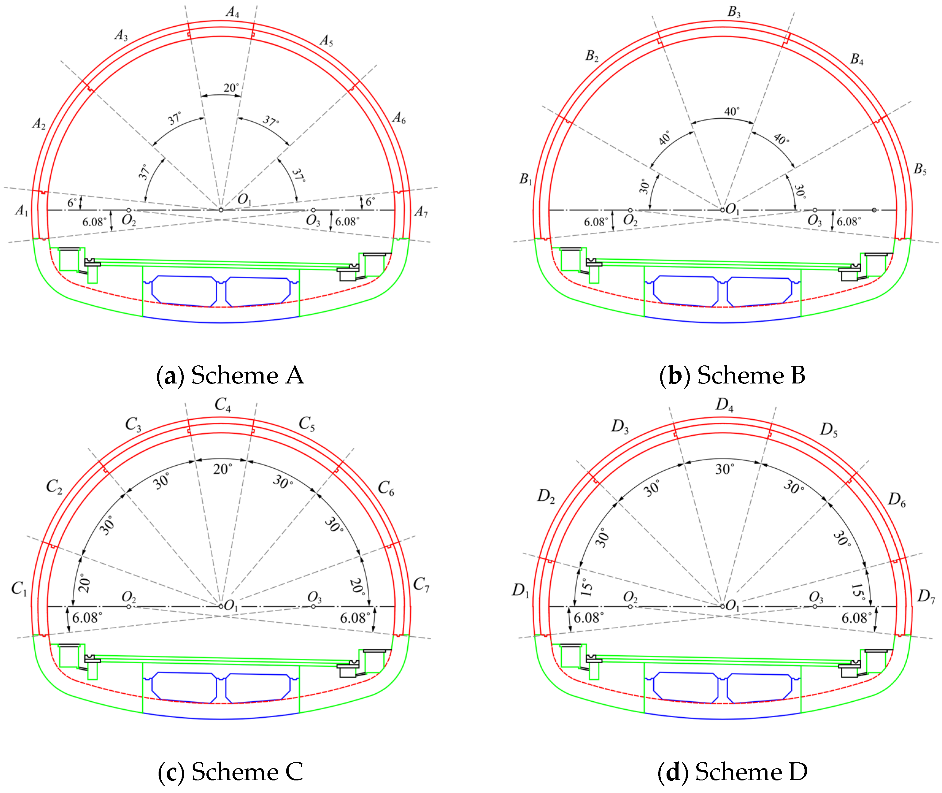
The secondary lining structure is constructed in a composite semi-prefabricated manner. The arch ring is divided into several segments, each with an inner layer of precast concrete segments and an outer layer of post-cast concrete. The inverted arch is divided into two post-cast springing sections on the left and right sides and a precast section in the middle. The total thickness of the tunnel’s secondary lining is 50 cm, with a precast arch ring layer of 30 cm and a post-cast layer of 20 cm. The material of the secondary lining is the C35 concrete of elastic modulus of 32.5 GPa, with a tensile strength limit of 2.5 MPa and compressive strength limit of 26.3 MPa. Joints between the precast segments are connected by straight bolts, for which M30 grade bolts are selected. Considering the structural stresses, the staggered joint assembly, as well as the manufacturing, transportation, installation, and waterproofing of the precast components, this study proposes two arch ring segmentation schemes: Scheme A (Figure 2a) is a five-segment assembly arch ring, while Schemes B, C, and D (Figure 2b–d) are seven-segment assembly arch rings. Due to the complex horseshoe-shaped cross-section used in this project, equal segmentation is difficult to achieve, so unequal segmentation is adopted.
The shield tunnel segment forms are generally flat-type and box-type reinforced concrete segments. Therefore, for the Class V surrounding rock section of highway tunnels constructed by the drilling and blasting method, the prefabricated secondary lining structure adopts a flat-type reinforced concrete lining. The shield tunnel segments are divided into two modes: equal segments and unequal segments, with unequal segmentation being more common. Highway tunnels constructed by drilling and blasting mainly have horseshoe-shaped cross-sections, which are relatively complex, making equal segmentation difficult to achieve. Thus, prefabricated segmental forms are mainly based on unequal segmentation. The tunnel lining type for the shield method construction mostly uses a single-layer lining, i.e., a prefabricated segment lining. Tunnel walls constructed by drilling and blasting are not as smooth as those constructed by the shield method. After blasting excavation, there often exist over-excavation or under-excavation conditions, and the tunnel walls are rough, making it inconvenient to use a single-layer lining. Therefore, composite lining is more appropriate. Considering the characteristics of the horseshoe-shaped tunnel cross-section and comprehensively taking into account factors such as structural stress, transportation, fabrication, installation of the prefabricated lining, and waterproofing performance, the segmentation form of the prefabricated secondary lining is formulated. Starting from the structural stress characteristics, the joints of the prefabricated secondary lining should be placed in areas with smaller bending moments. Four different segmentation schemes—A, B, C, and D (shown respectively in Figure 2a–d)—are proposed. Further calculation and analysis are conducted for each segmentation form to select the optimal scheme. In all schemes, only the upper arch ring of the secondary lining is segmented, while the inverted arch is installed by prefabricating the middle part of the inverted arch, while the left and right parts are casted in-place. It should be noted that the prefabricated part is rigidly connected to the cast-in-place parts simultaneously through the extended rebars and the post-cast concrete to avoid slipping.

2.2. The Geological Conditions

According to the statistical analysis by Zhou et al. [14] on the measured values of interlayer contact pressure in lining structures from 31 tunnels with different spans and surrounding rock grades, the secondary lining bears approximately 40–70% of the surrounding rock pressure in Class V rock. Herein, the secondary lining is assumed to bear 70% of the surrounding rock pressure, which is apparently a conservative value. According to the “Specifications for Design of Highway Tunnels” [15], the reduced horizontal pressure is calculated to be 88.42 kN/m2, and the vertical pressure is 221.05 kN/m2 (see Figure 1a). The geological survey report indicates that the surrounding strata of the tunnel consist of dolomite, dolomitic limestone, argillaceous sandstone, and shale. Using the theory of localized deformation, the elastic resistance exerted by the surrounding rock on the lining structure is calculated, with an average elastic resistance coefficient of 150 MPa/m.

3. Three-Dimensional Finite Element Model

3.1. The Shell-Spring Model

A three-dimensional shell-spring finite element model of the composite secondary lining structure is established using the Abaqus finite element program to calculate the internal forces and deformations of the structure under surrounding rock pressure. Specifically, three-dimensional shell elements are used to simulate each segment of the arch ring and the invert portion, while the circumferential and longitudinal joints between segments are simulated by equivalent springs. The connections between the arch ring and the invert, as well as between the prefabricated and cast-in-place parts of the invert, are modeled as rigid connections without the use of springs. The segment width is 2 m, and the mesh density is 10 cm. The elastic resistance of the surrounding rock is represented by normal-direction foundation springs, whose stiffness is calculated based on local deformation theory. These foundation springs are attached to each node of the shell elements, and their stiffness is calculated directly through the elastic resistance coefficient of 150 MPa/m for Class V rock. These springs are set to act only in compression, reflecting the mechanical behavior that foundation springs resist compression but not tension. Structural boundary conditions restrict movement and rotation out of the plane, and the surrounding rock pressure is applied to the model structure as line loads.

3.2. Calculation of Joint Stiffness

The joints of the composite semi-prefabricated secondary lining structure consist of inner bolts and an outer cast-in-place layer. Since the cast-in-place layer bears almost no tensile force, its stress pattern is similar to that of a fully prefabricated lining structure. Therefore, the segment joints are only equivalently modeled as rotational springs, axial springs, and shear springs in the plane. The Murakami–Koizumi method [16,17,18], commonly used in shield tunnel analysis, is adopted to calculate the equivalent stiffness of the joint springs. The calculation approach is as follows: first, the bolted connection between the segments is equivalently modeled as a tensile spring, and then the joint tensile stiffness coefficient is calculated, considering both the bolt tension and the compressive deformation of the bearing plates; next, the force-bearing area of the joint plate is modeled as a beam to approximate the bending stiffness generated by the joint plate; then, based on the reinforced concrete bending member cross-section, the neutral axis position of the joint connection is determined; finally, using the previously derived bolt tensile spring and joint plate bending spring, the moment–rotation relationship at the joint is obtained (see Figure 3b) and the equivalent bending stiffness of the joint is derived in Table 1.

4. Results and Discussions

In this section, a total of four continuous layouts of semi-prefabricated secondary linings using segmentation schemes A, B, C, and D are selected for calculation, in order to obtain an optimal segmentation under various situations. On the other hand, a total of six staggered seam layouts, including ones constructed sequentially by one A-ring and one B-ring (AB), by three A-rings and two B-rings (AAABB), by two A-rings and three B-rings (AABBB), by one C-ring and one D-ring (CD), by three C-rings and two D-rings (CCCDD), and by two C-rings and three D-rings (CCDDD), are selected to study the influences of the stiffness difference of adjacent rings, the longitudinal distribution of rings to the mechanical performance of the structures, noting that the stiffness difference between C- and D-rings is apparently larger than that between A- and B-rings.

4.1. Continuous Seam Layout

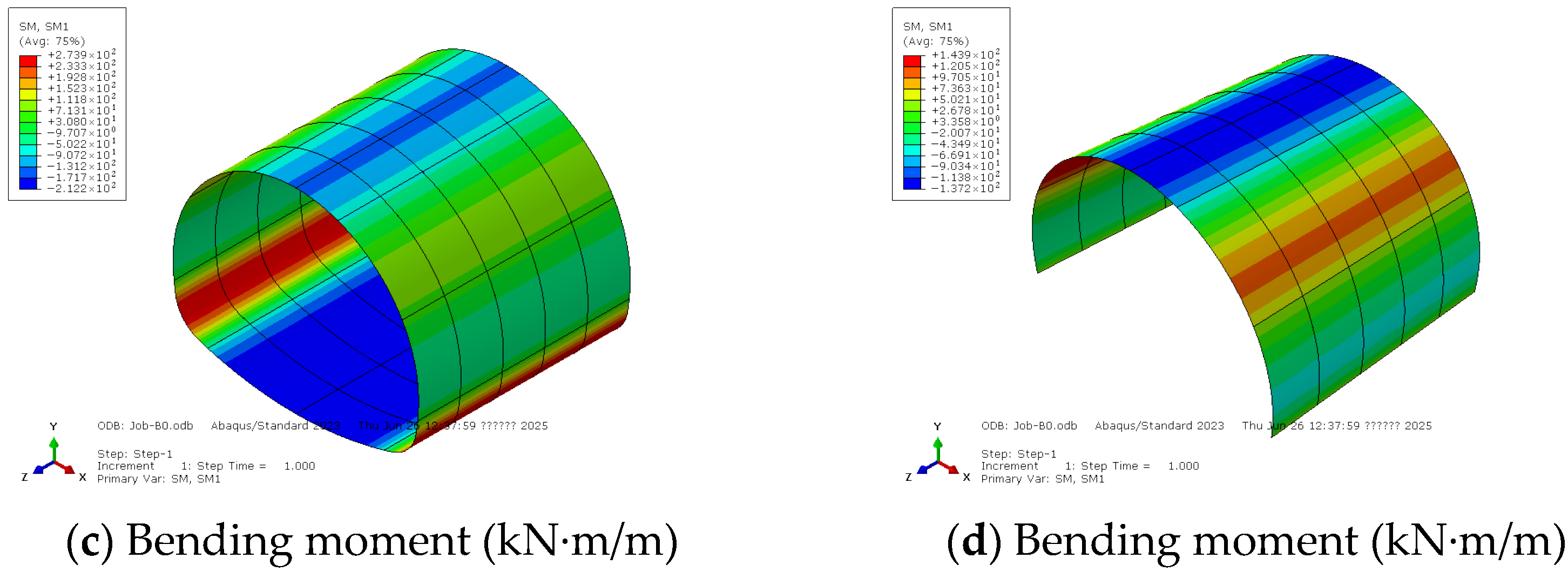
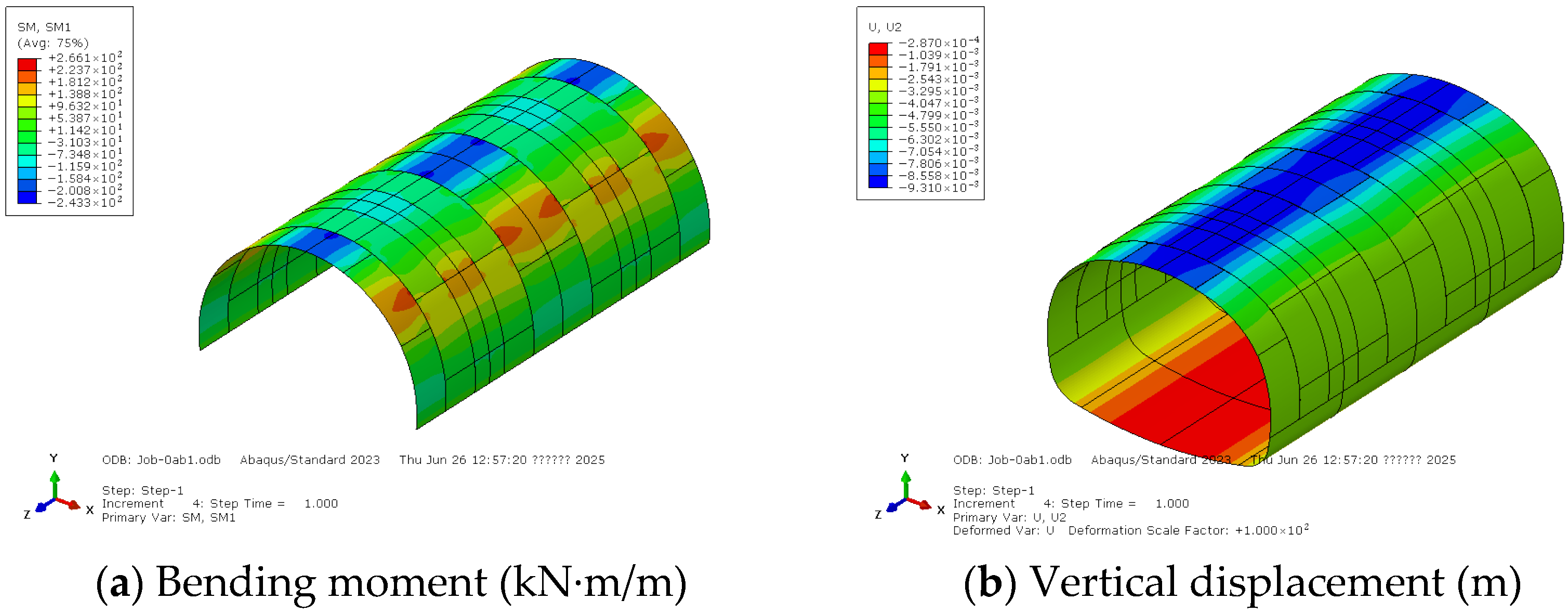
The contour diagrams of the computed internal forces and the deformation of the secondary lining with continuous seam layout constructed purely by Scheme A are shown in Figure 4. Before this, a mesh convergence analysis was implemented for Scheme A only, and the crown settlements computed using various mesh sizes of 40, 20, 10, and 5 cm are 9.02, 8.60, 8.57, and 8.57 mm, respectively; therefore the mesh size of 10 cm is sufficient to provide convergent results and will be applied to the following calculations. As can be seen, the arch crown and inverted arch undergo positive bending moment, which means the inner side is in tension and the outer side is in compression. Meanwhile, the arch shoulders and springings undergo a negative bending moment, which means the outer side is in tension and the inner side is in compression. The maximum positive bending moment of 212.2 kN·m/m for the full cross-section occurs at the inverted arch, while the maximum negative bending moment of 273.9 kN·m/m occurs at the springing. For the arch ring only, the maximum positive bending moment of 137.2 kN·m/m occurs at the crown, while the maximum negative bending moment of 143.9 kN·m/m occurs at the arch shoulder. The axial force throughout the structure is negative, indicating overall compression, and the axial force increases gradually from the crown to the springing. The minimum axial force at the crown is 1012 kN/m, while the maximum axial force at the springing is 1443 kN/m. The structural deformation shows overall settlement, and the maximum settlement at the crown is 8.57 mm.
The computed internal forces and deformation of the secondary lining with continuous joint layout for the other seven-segment schemes are listed in Table 2. According to these results, for the case of the continuous seam layout, Scheme A with a five-segment design exhibits the highest stiffness, which is close to that of a purely cast-in-place structure, resulting in the smallest deformation, since the joints are located near the zero-moment positions at the arch shoulder and arch crown. Among the three seven-segment schemes, the joints of Scheme B are located near the position of the maximum negative bending moment at the arch shoulder, leading to the lowest stiffness and the largest deformation. Meanwhile, Schemes C and D exhibit relatively higher stiffness. However, for Scheme C, the segments at the arch crown are too narrow (see Figure 2c), and the joints on both sides are located at positions of high positive bending moment, making its stiffness lower and deformation larger than that of Scheme D. Among all the schemes, only Scheme A does not exceed the tensile strength of plain concrete at the arch crown. The other three schemes, including the cast-in-place structure, fail to meet the safety requirements for the tensile strength of plain concrete at the arch crown. Therefore, it is necessary to provide sufficient circumferential reinforcement at this location to satisfy the relevant code requirements for concrete crack control.

4.2. Staggered Seam Layout

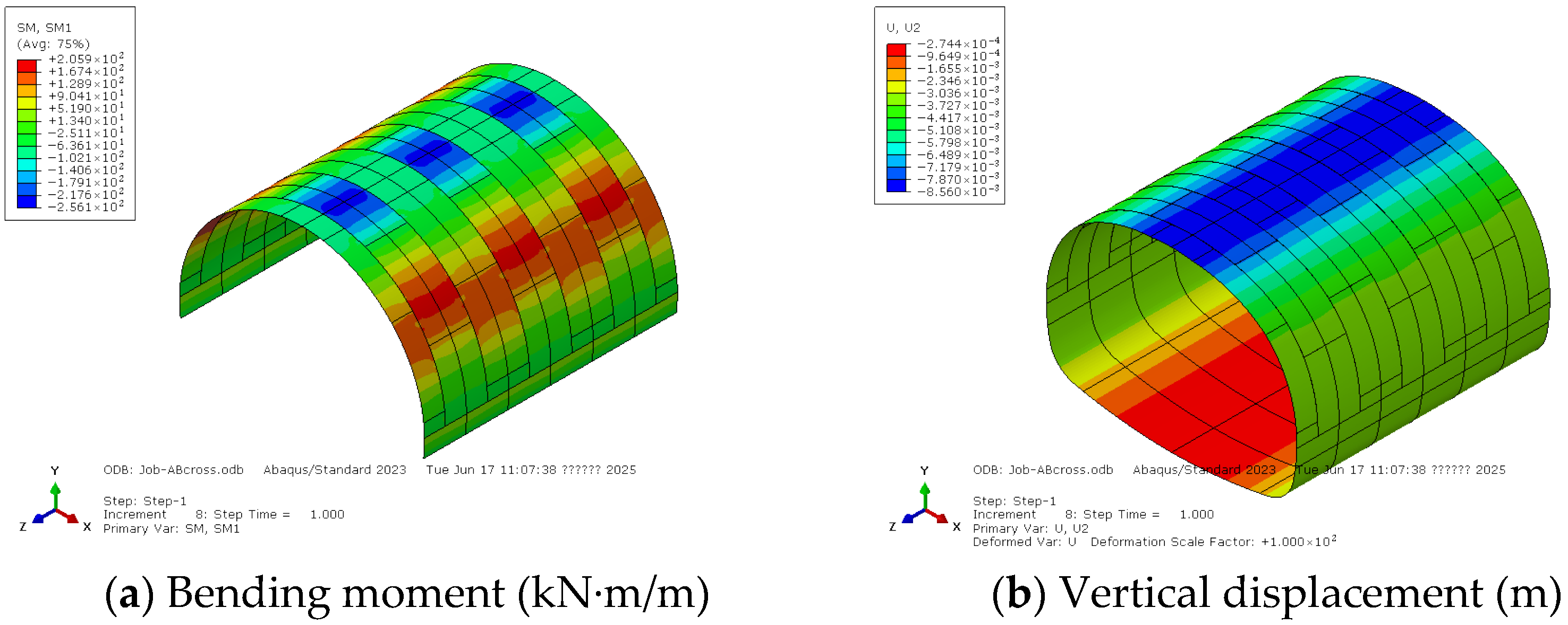
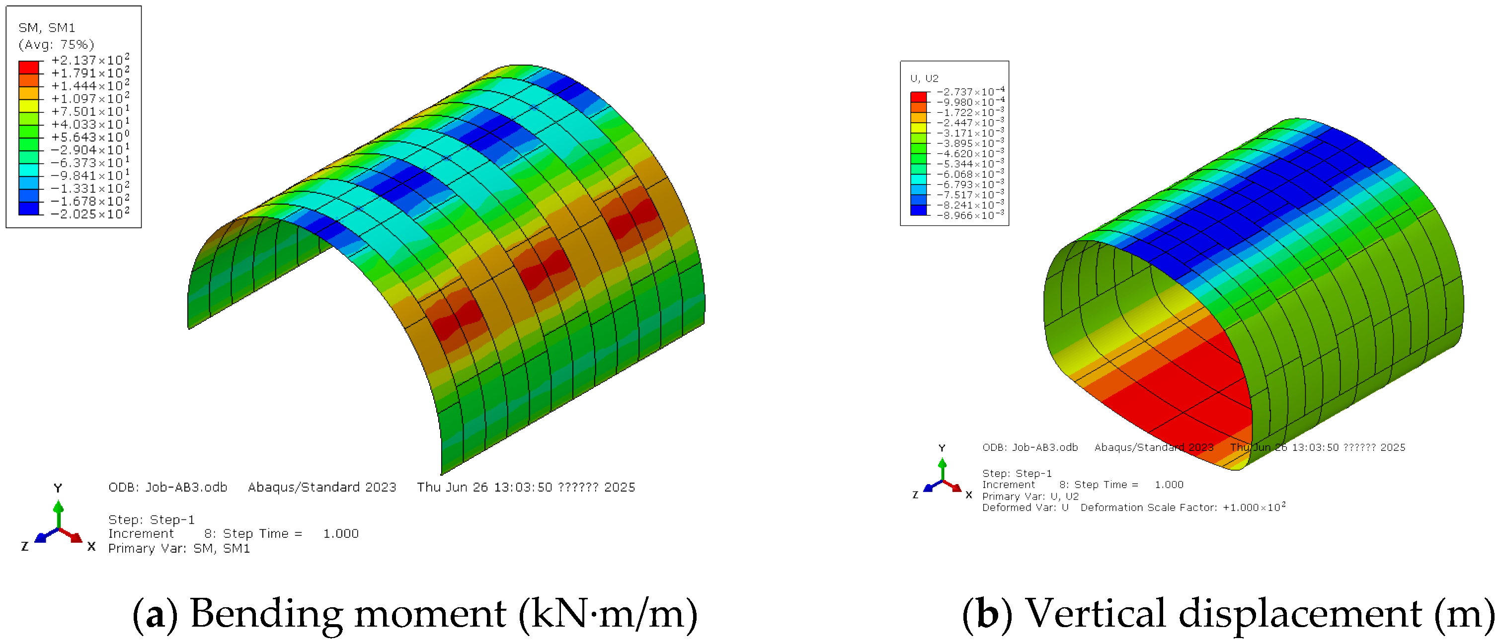
The contour diagrams of the computed internal forces and the deformation of the secondary lining with staggered seam layout constructed sequentially by one A-ring and one B-ring are shown in Figure 5. Similarly, the arch crown and the inverted arch undergo a positive bending moment, meanwhile the arch shoulders and springings undergo a negative bending moment, which means the outer side is in tension and the inner side is in compression. For the arch ring only, the maximum positive bending moment of 256.1 kN·m/m occurs at the crown, while the maximum negative bending moment of 205.9 kN·m/m occurs at the arch shoulder. The axial force throughout the structure is negative and increases gradually from the crown to the springing. If the force concentration effect near the longitudinal joints is not considered, the minimum axial force at the crown is 876 kN/m, while the maximum axial force at the springing is 1465 kN/m. The structural deformation shows overall settlement, and the maximum settlement at the crown is 8.56 mm.
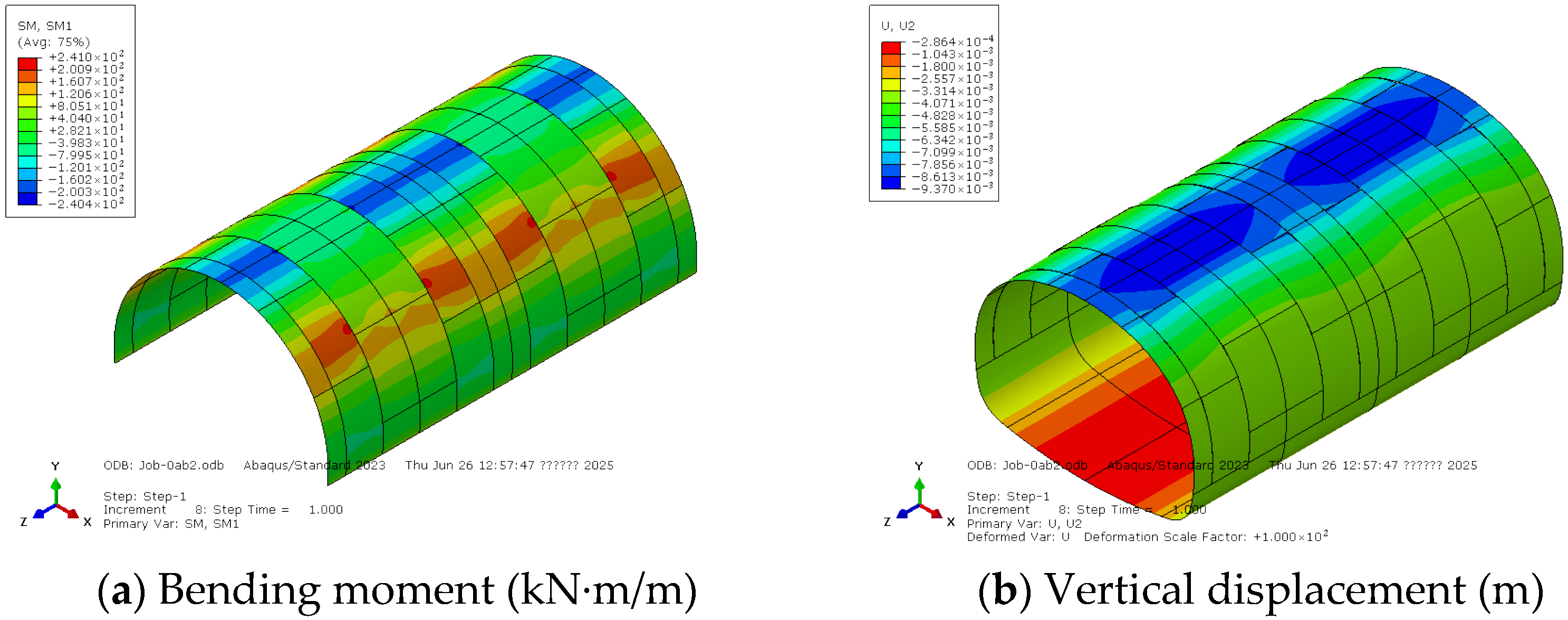
The contour diagrams of the computed internal forces and the deformation of the secondary lining with staggered seam layout constructed sequentially by three A-rings and two B-rings are shown in Figure 6. The arch crown and the inverted arch undergo a positive bending moment, while the arch shoulders and springings undergo a negative bending moment, which means the outer side is in tension and the inner side is in compression. For the arch ring only, the maximum positive bending moment of 240.4 kN·m/m occurs at the crown, while the maximum negative bending moment of 241.0 kN·m/m occurs at the arch shoulder. The axial force throughout the structure is negative and increases gradually from the crown to the springing. If the force concentration effect near the longitudinal joints is not considered, the minimum axial force at the crown is 892 kN/m, while the maximum axial force at the springing is 1512 kN/m. The structural deformation shows overall settlement, and the maximum settlement at the crown is 9.37 mm.
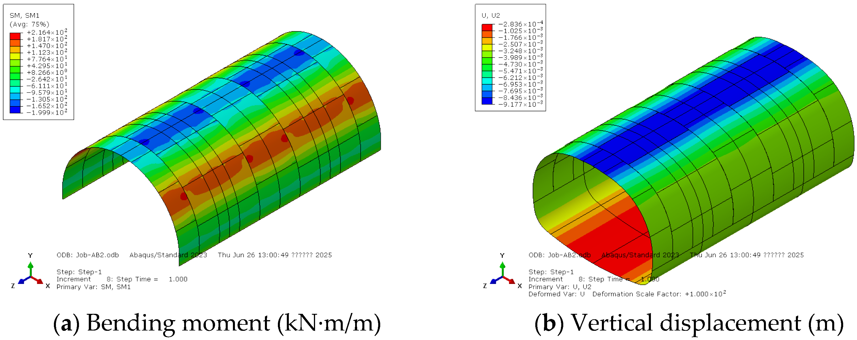
The contour diagrams of the computed internal forces and the deformation of the secondary lining with staggered seam layout constructed sequentially by two A-rings and three B-rings are shown in Figure 7. For the arch ring only, the maximum positive bending moment of 243.3 kN·m/m occurs at the crown, while the maximum negative bending moment of 266.1 kN·m/m occurs at the arch shoulder. The axial force throughout the structure is negative and increases gradually from the crown to the springing. If the force concentration effect near the longitudinal joints is not considered, the minimum axial force at the crown is 630 kN/m, while the maximum axial force at the springing is 1491 kN/m. The structural deformation shows overall settlement, and the maximum settlement at the crown is 9.31 mm.
The contour diagrams of the computed internal forces and the deformation of the secondary lining with staggered seam layout constructed sequentially by one C-ring and one D-ring are shown in Figure 8. For the arch ring only, the maximum positive bending moment of 202.5 kN·m/m occurs at the crown, while the maximum negative bending moment of 213.7 kN·m/m occurs at the arch shoulder. The axial force throughout the structure is negative and increases gradually from the crown to the springing. If the force concentration effect near the longitudinal joints is not considered, the minimum axial force at the crown is 876 kN/m, while the maximum axial force at the springing is 1497 kN/m. The structural deformation shows overall settlement, and the maximum settlement at the crown is 8.96 mm.
The contour diagrams of the computed internal forces and the deformation of the secondary lining with staggered seam layout constructed sequentially by three C-rings and two D-rings are shown in Figure 9. For the arch ring only, the maximum positive bending moment of 184.2 kN·m/m occurs at the crown, while the maximum negative bending moment of 285.6 kN·m/m occurs at the arch shoulder. The axial force throughout the structure is negative and increases gradually from the crown to the springing. If the force concentration effect near the longitudinal joints is not considered, the minimum axial force at the crown is 885 kN/m, while the maximum axial force at the springing is 1521 kN/m. The structural deformation shows overall settlement, and the maximum settlement at the crown is 9.88 mm.
The contour diagrams of the computed internal forces and the deformation of the secondary lining with staggered seam layout constructed sequentially by two C-rings and three D-rings are shown in Figure 10. For the arch ring only, the maximum positive bending moment of 199.9 kN·m/m occurs at the crown, while the maximum negative bending moment of 216.4 kN·m/m occurs at the arch shoulder. The axial force throughout the structure is negative and increases gradually from the crown to the springing. If the force concentration effect near the longitudinal joints is not considered, the minimum axial force at the crown is 854 kN/m, while the maximum axial force at the springing is 1499 kN/m. The structural deformation shows overall settlement, and the maximum settlement at the crown is 9.18 mm.
The computed internal forces and the deformation of all the secondary linings with staggered seam layout are concluded in Table 3. As can be seen, for the case of staggered seam layouts, due to the significant stiffness difference between adjacent rings, part of the surrounding rock pressure carried by the weaker rings is transmitted to the stronger rings through the longitudinal bolts. As a result, the internal forces in the stronger rings are greater than those constructed through the continuous seam layout. Compared to the second scheme with 3-ring and 2-ring staggering layouts, the structure with fully staggered rings has greater overall stiffness, more uniform force distribution, and no significant internal force concentration issues. Compared to the continuous seam layout for Scheme A in Table 2, the staggered seam layout AB has almost no effect on the structural stiffness, but significant increases in the tensile stress at the arch crown can be observed, meaning more circumferential reinforcement would be required. Therefore, due to the large stiffness difference between Schemes A and B, noting Scheme A is a five-segment design and Scheme B is a five-segment design, the staggered seam layout is not recommended for these two rings. On the other hand, the staggered seam layout CD results in a noticeable increase in stiffness compared to the respective continuous seam layouts given in Table 2, by reducing the settlement from 9.5 mm to 8.96 mm. In addition, the change in tensile stress at the arch crown is minimal. As can be seen, the tensile stress at the arch crown is slightly larger than the concrete tensile strength of 2.5 MPa, and one needs to set sufficient reinforcement near the crown to prevent concrete cracks. Therefore, when a seven-segment assembly scheme must be used and the surrounding rock near the tunnel is relatively weaker, it is recommended to adopt the staggered seam layout CD, since the structure stiffness is of most importance in this situation. It should be noted that the maximum settlement for various layouts ranges from 8.56 mm to 9.88 mm, these results agree with the observations of Tian et al. [19] for real tunnels in soft deposits and apparently satisfy the requirement of the Chinese standard [18], for which the limit for settlement is 10.25 m/400 = 25.63 mm.

5. Conclusions

In this paper, the semi-prefabricated second lining of highway tunnels constructed though various segmentation schemes is simulated using the 3D shell-spring finite element model, by considering both the continuous and staggered seam layouts. Such a shell-spring model simulates simply the joints connecting adjacent lining segments in both the circumferential and longitudinal directions as nonlinear springs, according to the Murakami–Koizumi method. Through the computed internal forces and the deformation of semi-prefabricated second linings under Class V surrounding rock pressure, the following mechanical properties can be concluded:
(a)
For the case of the continuous seam layout, the five-segment ring, with joints located near the zero-moment positions at the arch shoulder and arch crown, exhibits the highest stiffness.
(b)
For the case of the continuous seam layout, if the segment at the arch crown is too narrow, the joints will be located at positions of a high positive bending moment, leading to lower stiffness and thus larger deformation.
(c)
For the case of the staggered seam layout, part of the surrounding rock pressure carried by weaker rings is transmitted to stronger rings through the longitudinal bolts, resulting in larger internal forces in the stronger rings.
(d)
If the stiffness of two adjacent rings is close, the staggered seam layout will significantly improve the global stiffness of the lining and is advised to be applied in conditions of soft surrounding rock.
(e)
If the stiffness difference between two adjacent rings is too large, it is not advised to apply the staggered seam layout, since the global stiffness of the lining will not be improved while the internal forces will be increased.
From the above results, it is implied for engineering design that such segmentations with joints located near zero-moment positions of the arch is optimal and the crown segment should be wide enough to prevent large settlement. The staggered seam layout exhibits better global stiffness and is thus more appropriate for soft surrounding rock or more complicated dynamic loadings; moreover, a large stiffness difference between adjacent rings is not recommended, since stress concentration may be increased. In the future, the dynamic behavior of the proposed semi-prefabricated lining under seismic loadings, the long-term behavior considering creep, shrinkage, and temperature variation in concrete will be studied using the finite element model. Moreover, for in-service semi-prefabricated linings, the methods in [20,21] show potential for use in monitoring the mechanical performance, and one could additionally leverage computer vision [22,23] by using image segmentation to automatically detect, quantify, and monitor cracks or deformations.

Author Contributions

Conceptualization, Y.B. and H.B.; methodology, Y.B. and H.B.; software, Y.L.; validation, Y.L.; formal analysis, Y.B. and H.B.; investigation, Y.B. and H.B.; resources, Y.B.; data curation, Y.B. and H.B.; writing—original draft preparation, Y.B.; writing—review and editing, Y.Y.; visualization, Y.B.; supervision, Y.Y. All authors have read and agreed to the published version of the manuscript.

Funding

This research received no external funding.

Data Availability Statement

The data presented in this study are available upon request from the corresponding author. The data are not publicly available due to confidentiality.

Conflicts of Interest

Authors Yangyang Bao and Haitao Bao were employed by the company Road and Bridge International Corp., Ltd. The remaining authors declare that the research was conducted in the absence of any commercial or financial relationships that could be construed as a potential conflict of interest.

Abbreviations

The following abbreviations are used in this manuscript:
3DThree-dimensional
NATMNew Austrian Tunneling Method

References

  1. Hong, K.R. State-of-art and Prospect of Tunnels and Underground Works in China. Tunn. Constr. 2015, 35, 95. [Google Scholar] [CrossRef]
  2. Yao, Y.W.; Jiang, L.H.; Fan, Y.Q. Overview of Prefabricated Assembly Technology of Underground Space Structure. Urban Roads Bridges Flood Control 2012, 9, 286–292. [Google Scholar] [CrossRef]
  3. Huang, C.F. Analysis and computation on universal assembling segment lining for shield tunnel. Chin. J. Geotech. Eng. 2003, 3, 322–325. [Google Scholar] [CrossRef]
  4. Xiao, Z.P.; Li, W. Extrema analysis for internal forces and deformations of segment lining in large cross-section shield tunnels. Mod. Tunn. Technol. 2006, 5, 45–49. [Google Scholar] [CrossRef]
  5. Zeng, D.Y.; He, C. Analysis of the influence of segment assembling methods on the deformation and internal forces in the lining of a shield tunnel. Mod. Tunn. Technol. 2005, 2, 1–6. [Google Scholar] [CrossRef]
  6. Feng, S.K.; Guo, Z.X.; Liu, Y.; Pan, Q.; Xu, J.L.; Wang, G.L.; Xin, Q. Experimental study on the seismic performance of joints between sidewalls and floors in partially prefabricated subway station. Eng. Mech. 2023, 40, 190–201. [Google Scholar] [CrossRef]
  7. Jiang, H.X. Research on Key Connection Technology of Double-deck Precast Structure inside Shield Tunnel. Urban Roads Bridges Flood Control 2018, 10, 190–194. [Google Scholar] [CrossRef]
  8. Conforti, A.; Trabucchi, I.; Tiberti, G. Precast tunnel segments for metro tunnel lining: A hybrid reinforcement solution using macro-synthetic fibers. Eng. Struct. 2019, 199, 109628. [Google Scholar] [CrossRef]
  9. Yu, J.; Standing, J.; Vollum, R. Experimental investigations of bolted segmental grey cast iron lining behaviour. Tunn. Undergr. Space Technol. 2017, 61, 161–178. [Google Scholar] [CrossRef]
  10. Zhang, J.; Liu, X.; Ren, T. Structural behavior of reinforced concrete segments of tunnel linings strengthened by a steel-concrete composite. Compos. Part B Eng. 2019, 178, 107444. [Google Scholar] [CrossRef]
  11. Do, N.; Dias, D.; Oreste, P. 2D numerical investigation of segmental tunnel lining behavior. Tunn. Undergr. Space Technol. 2013, 37, 115–127. [Google Scholar] [CrossRef]
  12. Talmon, A.M.; Bezuijen, A. Calculation of longitudinal bending moment and shear force for Shanghai Yangtze River Tunnel: Application of lessons from Dutch research. Tunn. Undergr. Space Technol. 2013, 35, 161–171. [Google Scholar] [CrossRef]
  13. Zhang, L.; Feng, K.; Li, M. Analytical method regarding compression-bending capacity of segmental joints: Theoretical model and verification. Tunn. Undergr. Space Technol. 2019, 93, 103083. [Google Scholar] [CrossRef]
  14. Zhou, J.; Yang, X.A.; Cai, J. Study on secondary lining sharing ratio for deep-buried composite lining tunnel. J. Highw. Transp. Res. Dev. 2020, 37, 92–99. [Google Scholar] [CrossRef]
  15. JTG3370.1-2018; Specifications for Design of Highway Tunnels. China Communications Press: Beijing, China, 2018.
  16. Koizumi, A.; Murakami, H.; Nishino, K. Study on the analytical model of shield tunnel in longitudinal direction. Doboku Gakkai Ronbunshu 1988, 394, 79–88. [Google Scholar] [CrossRef]
  17. He, C.; Koizumi, A. Study on seismic behavior and seismic design methods in transverse direction of shield tunnels. Struct. Eng. Mech. 2001, 11, 651–662. [Google Scholar] [CrossRef]
  18. Saito, K.; Yamane, K.; Koizumi, A. A study on II seismic behavior of shield tunnel including shaft in longitudinal direction. J. Tunn. Eng. (JSCE) 2006, 16, 121–132. [Google Scholar] [CrossRef]
  19. Tian, Z.; Gong, Q.; Di, H.; Zhao, Y.; Zhou, S. What causes the excessive metro tunnel settlement in soft deposits: Learned from a detailed case with factor decomposition. Bull. Eng. Geol. Environ. 2022, 81, 212. [Google Scholar] [CrossRef]
  20. Tian, Z.; Yin, X.; Zhou, S. Learning loads on in-service underground infrastructure with a trans-dimensional Bayesian inversion method. Comput.-Aided Civ. Infrastruct. Eng. 2025, 40, 3750–3772. [Google Scholar] [CrossRef]
  21. Tian, Z.; Zhou, S.; Yin, X.; Yao, Q.; Zhao, Y. A Bayesian pressure-inversion–driven method for establishing mechanically grounded digital twins of in-service tunnel linings. Reliab. Eng. Syst. Saf. 2026, 265, 111633. [Google Scholar] [CrossRef]
  22. Kabir, H.; Wu, J.; Dahal, S.; Joo, T.; Garg, N. Automated estimation of cementitious sorptivity via computer vision. Nat. Commun. 2024, 15, 9935. [Google Scholar] [CrossRef] [PubMed]
  23. Song, Z.; Zou, S.; Zhou, W.; Huang, Y.; Shao, L.; Yuan, J.; Gou, X.; Jin, W.; Wang, Z.; Chen, X.; et al. Clinically applicable histopathological diagnosis system for gastric cancer detection using deep learning. Nat. Commun. 2020, 11, 4294. [Google Scholar] [CrossRef] [PubMed]
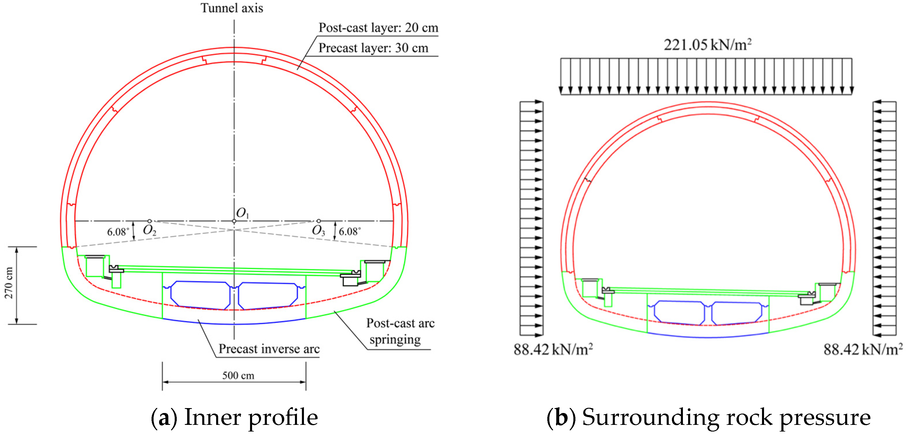
Figure 1. Inner profile of the second lining structure of the highway tunnel and the simplified surrounding rock pressure.
Buildings 15 03425 g001
Figure 2. Segmentation schemes of the semi-prefabricated secondary lining structure.
Buildings 15 03425 g002
Figure 3. The shell-spring model and the moment-rotation relation of circumferential joints.
Buildings 15 03425 g003
Figure 4. Contour diagrams of internal forces and deformation of the second lining with continuous seam layout.
Buildings 15 03425 g004aBuildings 15 03425 g004b
Figure 5. Contour diagrams of internal forces and deformation of the second lining with staggered seam layout AB.
Buildings 15 03425 g005
Figure 6. Contour diagrams of internal forces and deformation of the second lining with staggered seam layout AAABB.
Buildings 15 03425 g006
Figure 7. Contour diagrams of internal forces and deformation of the second lining with staggered seam layout AABBB.
Buildings 15 03425 g007
Figure 8. Contour diagrams of internal force and deformation of the second lining with staggered seam layout CD.
Buildings 15 03425 g008
Figure 9. Contour diagrams of internal forces and deformation of the second lining with staggered seam layout CCCDD.
Buildings 15 03425 g009
Figure 10. Contour diagrams of internal forces and deformation of the second lining with staggered seam layout CCDDD.
Buildings 15 03425 g010
Table 1. Rigidity parameters of circumferential joints.
Bolt GradeSeparationPositive MomentNegative Moment
Tension (MN/m)Bending (MN·m/rad)Angle
(deg)
Tension (MN/m)Bending (MN·m/rad)Angle
(deg)
M30Before10,8271167.31.3920,861705.11.3
After426.24610,460353.6
Table 2. Computed internal forces and deformation of second linings with continuous seam layout.
SchemesArch CrownArch ShoulderSettlement
(mm)
N 1
(kN)
M 2
(kN·m)
σ t  3
(Mpa)
σ c  4
(Mpa)
N
(kN)
M
(kN·m)
σ t
(Mpa)
σ c
(Mpa)
A1012137.21.275.321265−143.90.925.988.57
B953186.92.586.391284−106.80.005.139.73
C936194.22.796.531293−142.70.846.019.57
D953203.42.986.791299−117.10.215.419.42
1 N denotes the axial force in compression per width of 1 m. 2 M denotes the bending moment per width of 1 m. 3 σ t denotes the maximum tensional stress. 4 σ c denotes the maximum compressional stress.
Table 3. Computed internal forces and deformation of second linings with staggered seam layout.
SchemesArch CrownArch ShoulderSettlement
(mm)
N
(kN)
M
(kN·m)
σ t
(Mpa)
σ c
(Mpa)
M
(kNm)
M
(kN·m)
σ t
(Mpa)
σ c
(Mpa)
AB876256.14.397.901294−205.92.357.538.56
AAABB892240.43.997.551302−241.03.188.399.37
AABBB945243.33.957.731310−266.13.779.019.31
CD876202.53.116.611304−213.72.527.748.96
CCCDD956184.22.516.331298−285.64.269.459.88
CCDDD947199.92.906.691308−216.42.587.819.18
Disclaimer/Publisher’s Note: The statements, opinions and data contained in all publications are solely those of the individual author(s) and contributor(s) and not of MDPI and/or the editor(s). MDPI and/or the editor(s) disclaim responsibility for any injury to people or property resulting from any ideas, methods, instructions or products referred to in the content.