Abstract
To advance the application of sustainable recycled aggregate concrete (RAC) in bridge engineering, this study introduces a novel reinforced RAC-filled circular steel tubular (RRACFCST) column, leveraging the dual confinement of an external steel tube and an internal reinforcement cage. Its primary novelty is a comprehensive analytical framework integrating a new theoretical model by using limit analysis, ferrule theory, and the twin shear unified strength theory. Then, a rigorously validated nonlinear finite element model that incorporated material nonlinearity and interface effects was used to validate the proposed theoretical model. The results demonstrate the significant performance of the steel reinforcement cage, which enhanced the axial bearing capacity by 17.86%, and an optimal recycled aggregate replacement rate of 70% yielded the bearing capacity, with 100% replacement still achieving a 13.3% higher capacity than unconfined conventional concrete, demonstrating how effective confinement can compensate for and overcome the inherent deficiencies of RCA. Conversely, larger diameter–thickness ratios would reduce the strength by 33.7%. These quantifiable findings provide critical design insights and a validated predictive tool, establishing the RRACFCST column as a promising and high-performance sustainable solution for bridge structures.
1. Introduction
In the contemporary architectural design industry, which prioritizes structural safety, material reliability, economic viability, and environmental sustainability, the demand for high-performance building solutions has intensified. Steel structures, owing to their superior manufacturability, efficient assembly, exceptional strength-to-weight ratio, inherent ductility, ease of fabrication, and sustainable credentials, are now extensively utilized in construction engineering. Concurrently, recycled aggregate concrete (RAC)—a composite material incorporating crushed waste concrete as a partial or total replacement for natural aggregates—has emerged as a sustainable alternative. This innovation not only mitigates environmental pollution from concrete waste but also reduces the depletion of natural rock resources, thereby achieving the dual objectives of resource conservation and carbon emission reduction [1,2,3].
However, compared to natural aggregate concrete (NAC), recycled aggregate concrete (RAC) exhibits inherent microstructural deficiencies that govern its mechanical performance. These primarily include (I) the porous and mechanically weaker layer of old adhered mortar on the recycled concrete aggregate (RCA) surface, and (II) the presence of more numerous and weaker Interfacial Transition Zones (ITZs) between the old mortar and the original natural aggregate and between the new cement paste and the RCA. These microstructural flaws act as sites for stress concentration, facilitating microcrack formation and propagation under mechanical loading, which ultimately compromises RAC’s mechanical properties and permeability. The principal distinction between RAC and NAC therefore originates at the microstructural level within the aggregate phase and its interfaces, where the properties of the RCA dictate overall RAC performance. For instance, Jang et al. [4] demonstrated a counterintuitive relationship where a larger RCA particle size, despite its association with a higher content of weak residual mortar, corresponded to improved mechanical strength. This suggests that interlocking and aggregate skeleton effects may, in some cases, outweigh the detrimental impact of the mortar itself. Building on optimizing mechanical properties, Bian et al. [5] employed the response surface method to move beyond single-variable analysis, establishing a sophisticated regression model that identified an optimal combination of coarse aggregate content (45%), maximum size (16 mm), and shape (75% circular). Their work provides a valuable predictive framework for maximizing peak stress and elastic modulus, yet it primarily addresses the mechanical domain.
In contrast, the body of work on durability presents a more complex picture. Liang et al. [6] proposed a pre-treatment solution through carbonation, which improves compressive strength and notably reduces the risk of reinforcement corrosion by densifying the residual mortar. They found a linear relationship between chloride permeability and corrosion risk, which underscores the paramount importance of controlling ion transport. However, this pre-treatment process adds a layer of complexity and cost to RCA production. Conversely, Albuquerque et al. [7] took a structural design approach, confirming the detrimental effect of RCA on durability metrics like carbonation resistance. Their pragmatic solution of increasing the concrete cover thickness by 5 mm to counterbalance this effect effectively shifts the problem from material design to structural design, acknowledging the persistent permeability issue rather than resolving it at the material level. Fundamentally, RCA performance limitations stem from the porous, mechanically inferior old mortar layer adhering to aggregate surfaces. Studies confirm that optimizing RCA gradation and quality enhances RAC mechanical properties [8,9], whereas increased fine RCA substitution reduces chloride ion penetration resistance [10].
Significantly, the application of recycled aggregate concrete (RAC) within steel tubes has been established as an effective method to enhance its mechanical properties, creating recycled aggregate concrete-filled steel tubular (RACFST) columns [11]. This system synergistically combines the environmental benefits of RAC with the superior tensile strength and confinement effect of the steel tube, effectively mitigating the inherent drawbacks of these materials. Many studies have investigated the suitability of waste powders in concrete. For instance, Mahmoud et al. [12,13] confirmed that the incorporation of marble dust and granite dust as partial cement replacements in individual mixtures improved the physical, structural, and radiological properties of ordinary concrete. Empirical studies confirm that the confinement provided by the steel tube places the core RAC in a triaxial stress state, significantly boosting its compressive strength and deformation capacity while transforming its failure mode from brittle to ductile.
The performance of RACFST structures has been extensively investigated, with studies meticulously quantifying the influence of critical parameters such as the constraint coefficient and the recycled aggregate replacement rate. Scholars have developed advanced 3D finite element models incorporating sophisticated constitutive laws for RAC [14], evaluated existing design formulas for square sections [15], and explored the use of expansion agents to improve performance [16]. Further research has expanded understanding to encompass aspects such as post-fire behavior [17], seismic performance sensitivity [18], eccentric loading [19], and the behavior of rectangular sections [20]. Comprehensive works by Wang et al. [21] and Lyu et al. [22] have provided pivotal insights into stress–strain modeling, reliability analysis, and the formulation of design recommendations for RACFST stub columns.
However, a significant research gap still remains. For bridge piers and other critical compression members, the design may necessitate internal reinforcement to meet high flexural, shear, or combined load demands—requirements that a steel tube alone cannot always satisfy. Furthermore, current design codes often mandate the use of reinforcement cages for durability and redundancy reasons, even if the steel tube provides sufficient axial capacity. While the behavior of RACFST columns is well-documented, the performance of RACFST columns that are additionally reinforced with an internal steel cage—a system we term Reinforced RAC-Filled Circular Steel Tubular (RRACFCST) columns—has received scant attention. The interaction between the dual confinement provided by the external steel tube and the internal stirrups, and its synergistic effect on the mechanical properties of RAC, is not understood. This lack of knowledge presents a major barrier to the application of this highly promising, sustainable composite system in real-world bridge projects where reinforced sections are standard.
To address this gap, this study considers the combined constraining effects exerted by the steel tube and steel reinforcement cage, employing relevant theoretical methods to analyze and investigate the behavior of these columns under axial compression. Additionally, nonlinear finite element simulations were conducted utilizing ABAQUS (2019) software to comprehensively analyze the entire process of axial compression for the stub columns. This study not only advances the theoretical understanding of RRACFCST columns but also provides practical design insights for sustainable bridge construction. The proposed model and findings are directly applicable to the design of bridge piers, columns, and other compression members, offering a viable pathway for integrating recycled materials into mainstream infrastructure while maintaining structural performance and durability.
Building upon the advancements made by researchers in both domestic and international contexts, this paper investigates the axial compression bearing capacity of RRACFCST columns. The study considers the combined constraining effects exerted by the steel tube and steel reinforcement cage, employing relevant theoretical methods to analyze and investigate the behavior of these columns under axial compression. Additionally, nonlinear finite element simulations were conducted utilizing ABAQUS software to comprehensively analyze the entire process of axial compression for the stub columns. This study not only advances the theoretical understanding of RRACFCST columns but also provides practical design insights for sustainable bridge construction. The proposed model and findings are directly applicable to the design of bridge piers, columns, and other compression members, offering a viable pathway for integrating recycled materials into mainstream infrastructure while maintaining structural performance and durability.
2. Formula Derivation
2.1. Basic Assumption and Justifications
- (1)
- Yield criteria. The Von Mises yield criterion, which governs the multi-axial stress state, is adopted for the steel tube. For the RAC, the yield condition equation from Reference [23] is employed. This approach allows for the distinct material behaviors of steel and concrete to be incorporated into a unified limit analysis framework.
- (2)
- Steel Tube Stress State. In the limit state, the radial stress within the thin-walled steel tube is negligible compared to the hoop tensile stress and longitudinal stress. This simplification is grounded in classical thin-walled pressure vessel theory and is a standard assumption in the analysis of concrete-filled steel tubular (CFST) members [7]. It reduces the complex triaxial stress state to a manageable plane stress condition. Furthermore, the stress is assumed to be uniformly distributed across the tube wall thickness.
This assumption is valid for deriving a closed-form solution and holds well prior to the onset of significant local buckling. However, its accuracy may decrease for tubes with very high diameter-to-thickness ratios, where local buckling effects become pronounced and lead to a non-uniform stress distribution.
- (3)
- Tensile stress in RAC. Tensile stresses within the RAC are assumed to be negligible. Under dominant axial compression leading to ultimate failure, the primary failure mode is compressive crushing. The tensile strength of concrete is typically an order of magnitude lower than its compressive strength and thus has a minimal influence on the ultimate bearing capacity. This is a common and justified simplification for ultimate strength models of concrete composites [9], as it allows the derivation to focus on the compressive yield of concrete under confinement.
The primary limitation is that the model cannot capture the initiation and propagation of microcracks in the early elastic and inelastic phases of loading, which may affect the prediction of pre-peak stiffness and deformation characteristics. The model is therefore a strength-based, and not a serviceability-based, solution.
2.2. Bearing Capacity Analysis
The axial compressive bearing capacity of reinforced recycled aggregate concrete-filled circular steel tubular (RRACFCST) columns was analyzed, incorporating dual confinement mechanisms from the steel tube and reinforcement cage. This analysis establishes that the load-bearing capacity comprises four primary components: the outer steel tube, longitudinal reinforcement, outer ring RAC confined by the outer steel tube, and inner core RAC confined by both the outer steel tube and inner stirrup (Figure 1).
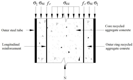
Figure 1.
Longitudinal section stress diagram of RACFCST tube column.
In the limit state, the static equilibrium conditions of the section (Figure 1) can be obtained as follows:
where N is the load action; As, Ar, Arc, and Acc are the cross-sectional areas of the outer steel tube, longitudinal reinforcement, outer ring RAC, and core RAC, respectively. σ1, σrc, and σcc are the longitudinal stress of the outer steel tube, outer ring RAC, and core RAC in the limit state, respectively. fr is the yield strength of longitudinal reinforcement.
2.2.1. Outer Ring and Core RAC Stress Analysis
Due to limited theoretical knowledge regarding the compressive strength of recycled aggregate concrete (RAC) in confined areas, the yield condition for concrete presented in reference [23] is employed to determine the limit state in this study.
RAC stress of outer ring:
RAC stress of core:
where fc is the axial compressive strength of RAC under an unconfined state, P is the effective lateral restraint stress of steel tube to RAC, and Pre is the effective lateral restraint stress of stirrup to RAC.
2.2.2. Steel Tube Stress Analysis
When the steel tube is in the limit state (Figure 2), according to the static equilibrium condition, it can be obtained that
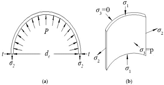
Figure 2.
Stress diagram of steel tube. (a) Steel tube section stress. (b) Micro-element stress of steel tube.
Steel ratio of steel tube:
Steel tube restraint effect system:
According to the Von Mises yield condition of steel tubes:
From the combination of Equations (4)–(7):
where σ2 is the circumferential tensile stress of the steel tube, t is the thickness of the steel tube, and dc is the inner diameter of the steel tube; θ is the constraint effect coefficient of the steel tube, which is a key dimensionless parameter that quantifies how effectively the steel tube confines the concrete. A higher θ value indicates stronger confinement and a greater enhancement of the concrete’s compressive strength. Ace is the nominal core RAC cross-sectional area of the steel tube package; fc is the axial compressive strength of RAC under unconstrained condition; and fy is the yield strength of the steel tube.
2.2.3. Determination of Effective Lateral Restraint Stress (P, Pre) of RAC by Steel Tube and Stirrup
- (1)
- Effective lateral restraint stress P of steel tube to RAC
It can be seen from the analysis (Figure 2b) that the effective lateral restraint stress P of steel tube to RAC is equal to the radial stress σ3 of the steel tube, that is,
According to reference [24], the axial stress expression of the steel tube can be obtained by using the twin shear unified strength theory; see the following Formula (10):
where σ3 is the radial stress of the steel tube, α1 is the tension–compression ratio of the steel tube, and α2 is the weighting coefficient. For steel tubes, α1 and α2 were selected as 1.0 and 0.5, respectively. ftt and ftc are the tensile yield stress and compressive yield stress of the steel tube, respectively. τts is the shear yield stress of the steel tube, and Γ is the inner diameter–thickness ratio of the steel tube.
We substituted Formulas (4), (9), and (10) into the Von Mises yield criterion, Formula (11), under the three-dimensional stress state of the steel tube.
By examining Formula (12), we observe that the effective lateral restraint stress P exerted by the steel tube on the RAC is influenced by the inner diameter–thickness ratio Γ and the yield strength fy of the steel tube. Table 1 provides the values for the effective lateral restraint stress P of the steel tube on RAC for various inner diameter–thickness ratios and yield strengths of the steel tube. It is worth noting that the range of parameter settings for the diameter-to-thickness ratio is constrained due to the limited availability of steel tube materials.

Table 1.
The value of effective lateral restraint stress P.
- (2)
- The effective lateral restraint stress of stirrups (Pre) on RAC
The steel reinforcement cage is mainly the transverse restraint effect of stirrups on RAC. Mander et al. [25] gave a more classical model of effective lateral restraint of stirrups when studying stirrup-confined concrete (Figure 3). This stress is not uniform but is a function of the stirrup spacing, area, and yield strength, reflecting the fact that confinement is most effective between stirrups. The effective lateral restraint stress of stirrups (Pre) on RAC in this paper is
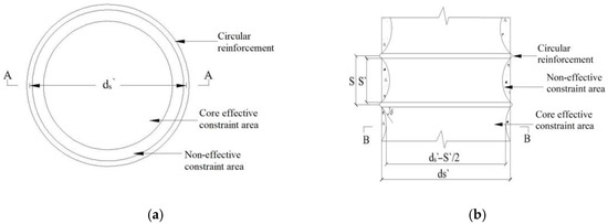
Figure 3.
The effective confined area of concrete bounded by circular stirrups. (a) A–A cross-section. (b) B–B cross-section.
Effective constraint coefficient:
Stirrup restraint stress:
where S is the stirrup spacing, S′ is the net distance of stirrups, d′s is the diameter of the circle surrounded by stirrups, ρcc is the ratio of the area of longitudinal reinforcement to the core area of the section surrounded by the stirrup centroid, and n is the number of longitudinal reinforcement; dP is the diameter of longitudinal reinforcement; Asp and fyh are the cross-sectional areas and yield strength of stirrups, respectively.
2.3. Calculation Formula of Axial Compression Bearing Capacity
The expression for ξ was derived through regression analysis based on experimental data from axial compression tests on recycled aggregate concrete-filled steel tubular (RACFST) columns reported in Reference [26]. The dataset comprised peak load values for specimens with RCA replacement ratios of R = 0%, 30%, 50%, 70%, and 100%. A nonlinear least-squares regression was performed using MATLAB 2019a, yielding the following quadratic expression:
where ξ is reduction coefficient of RAC, and R is the replacement rate of recycled aggregate. The form of the equation captures the nonlinear trend observed in the experimental results, where the bearing capacity initially decreased with increasing R, then stabilized or slightly improved due to internal curing effects at higher replacement levels. This reduction coefficient was applied to the nominal core concrete strength to reflect the reduced confinement effectiveness and composite behavior in RRACFCST columns with recycled aggregates.
Formulas (2), (3), (8), and (17) were substituted into Formula (1) to obtain the calculation formula of the axial compression bearing capacity of reinforced recycled aggregate concrete-filled circular steel tubular stub columns:
Among them, the p value can be found in Table 1, and Pre can be calculated by Formula (16). The simplified formula for the axial compressive bearing capacity of recycled concrete-filled circular steel tubular stub columns is shown in Formula (19).
where Ace is the nominal core RAC cross-sectional area of the steel tube package; fc is the axial compressive strength of RAC under unconstrained conditions; θ is the constraint effect coefficient of steel tube; ρs is the reinforcement ratio of steel tube reinforced recycled concrete; ω is the ratio of yield strength of longitudinal reinforcement to axial compressive strength of RAC; ξ is the reduction coefficient of RAC; and ψ is the ratio of the core RAC cross-sectional area Acc to the nominal core RAC cross-sectional area Ace wrapped.
Equation (19) can be intuitively understood by decomposing it into four terms: (I) Steel tube contribution (1st term). This is the straightforward yield capacity of the external steel tube acting as a traditional column. (II) Longitudinal reinforcement contribution (2nd term). This represents the yield capacity of the internal steel reinforcement cage, which acts as a conventional reinforced concrete column core. (III) Core concrete contribution (3rd term). This term represents the enhanced strength of the recycled concrete at the core of the section. (IV) Outer ring concrete contribution (4th term). This term accounts for the concrete between the reinforcement cage and the steel tube. It is also enhanced by confinement, primarily from the effective lateral restraint stress provided by the steel tube.
3. Establishment of Finite Element Model
ABAQUS finite element software was utilized to analyze the mechanical behavior of RRACFCST stub columns subjected to axial compression, employing a constitutive relation model. In the modeling process, Q345 steel was employed as the material for the steel components. The simulation parameters, as presented in Table 2, pertain to low-carbon steel.
Table 2.
Steel model parameter table.
3.1. Selection of Material Constitutive Model
3.1.1. Steel Constitutive Model
In this study, the constitutive model used for steel follows a simplified secondary flow plastic model that adheres to the Von Mises yield criterion. The simplified stress–strain relationship curve, as depicted in Figure 4, encompasses five distinct stages: the elastic stage (0–a), elastic–plastic stage (a–b), plastic stage (b–c), strengthening stage (c–d), and secondary flow plastic stage (d–e). In this context, fp, fy, and fu represent the proportional limit, yield strength, and tensile strength of the steel, respectively.
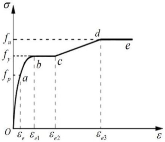
Figure 4.
Diagram of stress–strain relationship of steel.
The mathematical expression of the stress–strain curve is [16]:
In Formula (20),
where σs and εs are the stress and strain of steel, respectively, fy is the yield strength of steel, and Es is the elastic modulus of steel.
3.1.2. Selection of RAC Constitutive Model
In this model of steel tube reinforced recycled concrete, the RAC experiences a three-dimensional compression state within the steel tube. Therefore, it was necessary to consider the compression constitutive relationship of RAC. Given that ABAQUS software incorporated the restraint effects of both the steel tube and steel reinforcement cage on the RAC, this study adopted the uniaxial compression constitutive model for RAC under varied substitution rates, as outlined in reference [26].
In Formula (21),
where ε0 is the peak strain of recycled concrete, fcR is the axial compressive strength of recycled concrete under different replacement rates, β and γ are control parameters, and R is the replacement rate of recycled aggregate.
Under axial compression, the failure mode of RAC stub columns was predominantly compressive, with negligible tensile effects. Within the finite element software framework, three methods are available to characterize concrete tensile softening: the tensile stress–strain relationship, stress–crack width relationship and stress–fracture energy relationship. Following Reference [27], the stress–fracture energy relationship is recommended for defining the RAC model due to its superior convergence characteristics. Consequently, this approach was adopted in this study to characterize the tensile behavior of RAC, with corresponding parameters detailed in Table 3.
Table 3.
RAC model parameter table.
The elastic modulus Ec of RAC should be determined by experiments. In the absence of experimental data, it can be determined according to the formula of RAC elastic modulus given in reference [28]:
where E0 is the elastic modulus of concrete when the replacement rate of recycled coarse aggregate is 0%.
3.2. Contact Definition
Within the RAC column, the steel reinforcement cage was embedded, and a surface-to-surface contact element was utilized between the outer steel tube and the inner core RAC. This contact element treated the outer steel tube, which possessed higher stiffness, as the master surface, and the core RAC as the slave surface. The interface model between the RAC and steel tube incorporated hard contact in the normal direction and bond–slip behavior in the tangential direction (Figure 5). Tangential forces at the interface were simulated using the column friction model, where the shear stress τ was compared with the critical shear stress τcrit. A friction coefficient of 0.25 was assigned to the interface, whereas the normal contact was defined as hard contact, thereby permitting potential separation of the master and slave surfaces.
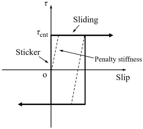
Figure 5.
Column friction model.
3.3. Unit Type and Grid Division
In this study, the outer steel tube was modeled using a four-node curved shell element (S4R), the core RAC was discretized with an eight-node linear reduced-integration 3D solid element (C3D8R), and the steel reinforcement bars were represented by truss elements (T3D2). Initially, a medial axis algorithm was employed to partition the model into simplified regions, which were subsequently meshed using the structured meshing technique (Figure 6).
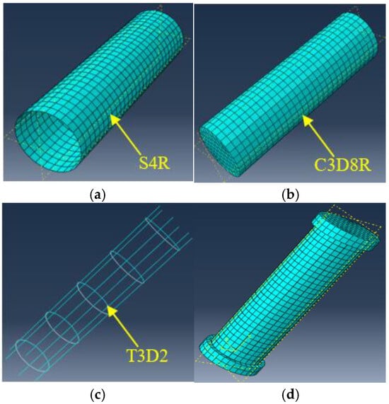
Figure 6.
Sketch diagram of meshing for each part of the stub column. (a) Steel tube. (b) Core RAC. (c) Steel reinforcement cage. (d) Steel tube reinforced RAC stub column.
To ensure the accuracy and convergence of the finite element model, a mesh sensitivity analysis was conducted. Three mesh sizes were considered: coarse (40 mm), medium (25 mm), and fine (15 mm). The axial compressive load capacity and stress distribution of a representative RRACFCST stub column (RRACFCST-7) were compared across these mesh sizes. The results indicate that the medium mesh (25 mm) provided a balance between computational efficiency and accuracy, with a deviation of less than 2% compared to the fine mesh. The coarse mesh led to an underestimation of the bearing capacity and localized stress concentrations, while the fine mesh resulted in significantly increased computational time without substantial improvement in accuracy. Therefore, the medium mesh size (25 mm) was adopted for all subsequent simulations.
3.4. Boundary Conditions and Loading Methods
In the finite element simulation, the lower end of the column was imposed with three displacement constraints (U1 = U2 = U3 = 0), while the upper end was subjected to a coupling constraint with restricted displacements (U1 = U2 = 0). For this model, a dedicated analysis step was defined, and nonlinear analysis was implemented. To ensure the convergence of the model, a displacement-controlled load was applied at the coupling loading point.
3.5. Analysis of Finite Element Simulation Results
One of the distinguishing features of ABAQUS (2019) software is its comprehensive range of concrete material constitutive models, including the Smeared Crack Concrete Model (SCCM), the Brittle Cracking Model (BCM), and the Concrete Damage Plasticity Model (CDP), among others. The SCCM is suitable for static analysis and requires fewer parameters, but it may encounter convergence issues. The BCM is primarily used in the ABAQUS/Explicit module specifically for explicit dynamic analysis. On the other hand, the CDP model, which incorporates an elastoplastic framework, adequately represents the damage in both compression and tension structures and demonstrates good convergence. Therefore, for the present study, the CDP model was considered the most appropriate choice.
In this study, the proposed model was verified and validated using three sets of experimental specimens from the existing literature: the N32LS-C steel reinforcement cage specimen [29], the CA-10 recycled concrete-filled steel tube specimen [30], and the RCFS-100-1 steel tube-confined reinforced recycled aggregate concrete specimen [31]. Specifically, comparisons are conducted on the ultimate axial bearing capacity and load-strain curves, with all discrepancies falling within an acceptable range. These comparisons served to confirm the appropriateness of the selected material models, interface contact settings, and element types for investigating circular steel tube (confined) reinforced recycled concrete stub columns. Additionally, the failure mode of such stub columns was examined through numerical simulation.
The specific parameters of the CA-10 specimen were detailed as follows: The stub column has a sectional diameter of 88.30 mm and a height of 283.50 mm; the steel tube has a wall thickness of 2.51 mm; the prism compressive strength of RAC is 29.2 MPa; the replacement ratio of recycled coarse aggregate is 100%; the yield strength of the steel tube is 342.7 MPa; the confinement factor is 1.801; and the experimental ultimate bearing capacity is 540.96 kN. The longitudinal reinforcement comprises six Φ6 steel bars, while the stirrups are Φ3 steel bars arranged at a spacing of 60 mm. The diameter of the steel reinforcement cage is 58 mm, and the thickness of the concrete cover is 11.15 mm.
The parameters of the RCFS-100-1 specimen from reference [31] are as follows: the specimen height is 400 mm; the inner diameter of the steel tube is 192.04 mm, with a wall thickness of 3.63 mm; the replacement ratio of recycled coarse aggregate is 100%; the prism compressive strength of RAC is 29.7 MPa; the yield strength of the steel tube is 465 MPa; and the confinement coefficient is 1.21.
Figure 7 presents a schematic diagram illustrating the damage morphology of the specimen obtained from finite element simulation. Figure 7a depicts the overall failure mode of the component, showing compressive buckling in the middle portion of the specimen with significant deformation. Figure 7b,c reveals that, as the load increases, the stress in each section of the stub column gradually intensifies, particularly in the steel tube and steel reinforcement cage. Figure 7d provides a stress contour of the recycled aggregate concrete (RAC). Initially, under the initial load, the RAC between the steel tube and steel reinforcement cage remains uncompressed. However, as the load increases, microcracks within the RAC continue to propagate, leading to lateral expansion that exceeds that of the steel tube and steel reinforcement cage. The RAC is subjected to lateral restraint from the steel tube and steel reinforcement cage, thereby enhancing its strength.
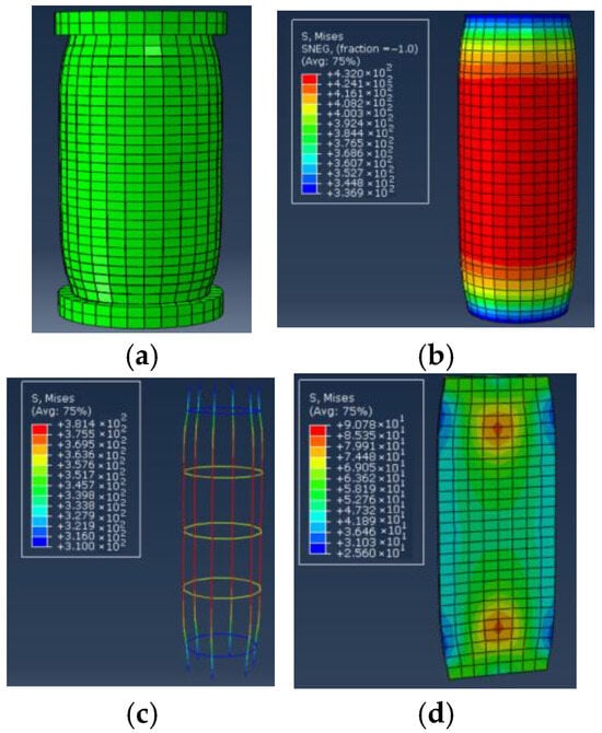
Figure 7.
Schematic diagram of failure mode of the stub column. (a) RACFCST stub column, (b) steel tube, (c) steel reinforcement cage, (d) RAC.
Figure 8 demonstrates a comparison between the finite element simulation curve and the experimental curve. The results indicate that the finite element simulation of the steel tube (confined) reinforced recycled aggregate concrete was in good agreement with the experimental findings. Specifically, in Figure 8a, the peak load of the experimental curve was 540.96 kN, while that of the finite element simulation curve reached 557.17 kN, with the error controlled at approximately 3%. In Figure 8b, the peak load of the experimental curve was 2232 kN, and that of the finite element simulation curve was 2147 kN, showing an error controlled at around 4%. It is evident that the errors in both simulations were minimal, with both remaining below 5%. This outcome verifies the reliability of the modeling method, confirming its applicability in the simulation study of circular steel tube (confined) reinforced recycled concrete stub columns.
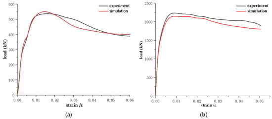
Figure 8.
Comparison of the finite element simulation curves and the experimental curves. (a) Comparison of load–strain curves of RRACFCST. (b) Comparison of load–strain curves of STCRRAC.
Comprehensive analysis indicated that, when the axial force reached approximately 85% of the peak load, the steel tube entered a yielding state, accompanied by obvious bulging in the middle section of the stub column. As the load continued to increase toward the peak value, significant overall deformation of the specimen occurred; at the deformation location, both the steel reinforcement cage and the steel tube yielded, resulting in a gradual decrease in the bearing capacity of the component. The aforementioned finite element simulation effectively captured the stress evolution and deformation characteristics of the circular steel tube-reinforced recycled concrete stub column under axial loading.
4. Study on Axial Compression Performance
4.1. Parametric Design of Model
The properties of the CA steel tube and RAC material in reference [30] were selected as the standard, and the HRB400 and HRB335 models of steel reinforcement were selected as the standard. Specific parameters of stub column specimens: Column height (H) is 550 mm and diameter (D) is 219 mm; the yield strength of the steel tube is 342.7 MPa, the ultimate strength is 420 MPa, and the wall thickness (t) of the steel tube is 3 mm, 4 mm, and 6 mm. According to the calculation formula (D/t), the diameter-thickness ratio of the steel tube is 73.00, 54.75, and 36.50, respectively. The longitudinal reinforcement is an HRB400 rebar with a diameter of 10 mm, a cross-sectional area of 78.50 mm2, and a yield strength of 400 MPa. The stirrups are HRB335 steel bars with a diameter of 6 mm, a cross-sectional area of 28.26 mm2, a yield strength of 335 MPa, and a stirrup spacing of 100 mm. The recycled coarse aggregate replacement ratio (r) is 0%, 30%, 50%, 70%, and 100%, respectively. The diameter of the stirrup center dh is 183 mm. The specimen parameters are summarized in Table 4.
Table 4.
Parameters of specimens.
4.2. Model Analysis
The RRACFCST-7 specimen and CSTCRRAC-7 specimen were selected for column analysis. From Figure 9 and Figure 10, it is evident that the stresses in the steel tube and steel reinforcement cage increased rapidly at the initial stage of loading, with significant bulging observed in the middle of the specimens. Specifically, the steel tube of specimen RRACFCST-7 (Figure 9a) yielded earlier than that of specimen CSTCRRAC-7 (Figure 9b). Figure 11 presents the stress contour of RAC. Under initial loading, the RAC, steel tube, and steel reinforcement cage deformed coordinately without any extrusion. However, as the load increased, internal microcracks in the RAC continued to propagate and coalesce, leading to lateral expansion that exceeded that of the steel tube and steel reinforcement cage. Consequently, the RAC was subjected to three-dimensional lateral confinement from the steel tube and reinforcement cage, resulting in enhanced strength.
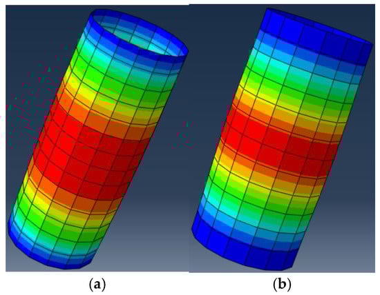
Figure 9.
Steel tube stress diagram. (a) RRACFCST-7 specimen steel tube. (b) CSTCRRAC-7 specimen steel tube.
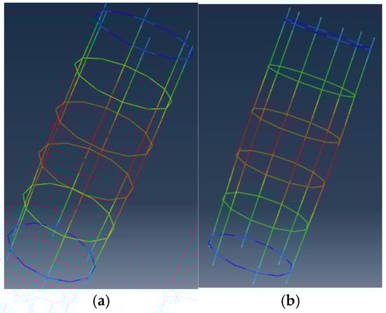
Figure 10.
Steel reinforcement cage stress diagram. (a) RRACFCST-7 specimen steel reinforcement cage. (b) CSTCRRAC-7 specimen steel reinforcement cage.
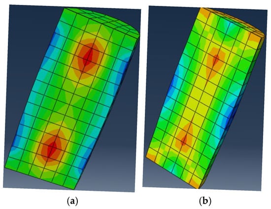
Figure 11.
RAC force cloud diagram. (a) RRACFCST-7 specimen of RAC. (b) CSTCRRAC-7 specimen of RAC.
As shown in Figure 12, the load–strain curves of the two specimens exhibit similar characteristics, with three distinct stress stages. The first stage corresponds to the elastic phase of the specimens, where the load increases linearly with strain; specifically, the load value rises gradually with increasing strain according to a set of characteristic parameters. During this phase, the steel tube, steel reinforcement cage, and RAC deform in coordination, with no visually observable deformation.
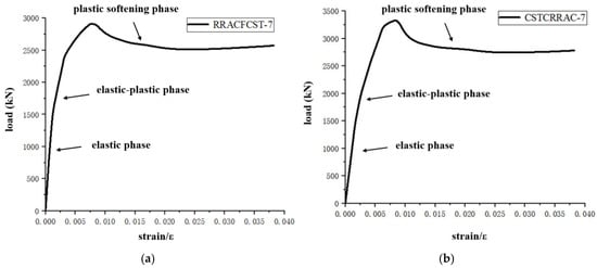
Figure 12.
Specimen strain load curve. (a) RRACFCST-7 specimen steel reinforcement cage. (b) CSTCRRAC-7 specimen steel reinforcement cage.
The second stage represents the elastic–plastic phase. Here, strain continues to increase while the load grows at a slower rate. At this point, the RAC undergoes significant lateral deformation, and the lateral confinement imposed by the steel tube and reinforcement cage on the RAC intensifies.
The third stage is the plastic softening phase. For the specimen RRACFCST-7, since the outer steel tube directly bears the load, its steel tube yields earlier than that of the specimen CSTCRRAC-7, resulting in a lower peak bearing capacity compared to the latter. With further increases in strain, the curves of both specimens decrease gradually. The ultimate bearing capacities of all specimens are summarized in Table 5.
Table 5.
Finite element ultimate bearing capacity results.
4.3. Ultimate Bearing Capacity Analysis
Figure 13 illustrates the load–strain relationship curves of reinforced recycled aggregate concrete circular steel tubular (confined) columns under different recycled coarse aggregate replacement rates. Figure 14 examines the influence of the recycled coarse aggregate replacement rate on the ultimate bearing capacity of the stub columns. Observations from Figure 13 and Figure 14 reveal that, as the recycled coarse aggregate replacement rate increases, the peak load of the specimens first decreases and then gradually increases, with the ultimate bearing capacity reaching its maximum at a 70% replacement rate.
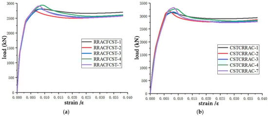
Figure 13.
Load–strain curves of RRACFCST and CSTCRRAC stub columns under different replacement rates. (a) Load–strain curve of RRACFCST stub column. (b) Load–strain curves of CSTCRRAC stub column.
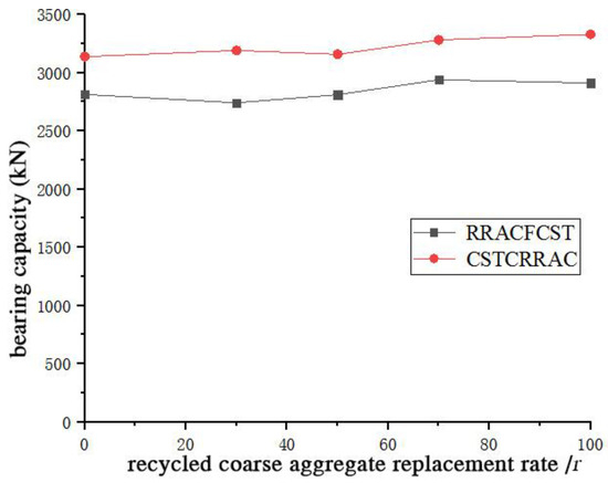
Figure 14.
Influence of substitution rate on bearing capacity.
The subsequent strength recovery and peak at a 70% replacement rate can be mechanistically explained by two key factors. (I) The Pore-Filling Effect: an optimal content of finer particles from crushed RCA can improve particle packing density within the concrete matrix, enhancing compactness—a particular benefit under the triaxial stress state from steel tube confinement [32]. (II) The Enhanced Confinement Efficacy: the more porous RCA exhibits higher lateral dilation under axial load compared to natural aggregate [16]. In a confined system, this greater dilation activates the confining pressure from the steel tube earlier and more strongly. This enhanced confining stress more effectively suppresses microcrack propagation, leading to a greater improvement in peak strength and ductility that can offset the inherent weakness of RCA [21]. The peak at 70% represents an optimal balance where these benefits outweigh the aggregate’s drawbacks.
The notion of “internal curing” is a valid mechanism for improving long-term hydration [33] but is less likely to dominate the short-term peak strength observed in these tests. The primary drivers are the physico-mechanical mechanisms of dilation and confinement. This is further underscored by the CSTCRRAC specimen, which achieved its highest capacity at a 100% replacement rate. Its superior performance highlights the critical role of confinement, as its design provides more effective and continuous restraint by preventing the premature yielding of the steel tube.
The reduction in axial compressive bearing capacity is attributed to the presence of a mortar layer on the surface of recycled coarse aggregates and the inherent damage incurred during their processing. Conversely, the favorable water absorption capacity of recycled coarse aggregates enables them to absorb and release mixing water during the mixing process, which exerts an internal curing effect and thereby enhances the axial compressive bearing capacity of the specimens.
4.4. Effect of Reinforcement Ratio on the Ultimate Bearing Capacity
Figure 15 presents the load–strain relationship curves of reinforced recycled aggregate concrete circular steel tubular (confined) columns under varying reinforcement ratios. As observed from Figure 15, incorporating a steel reinforcement cage within the steel tube (confined) recycled concrete effectively enhances the ultimate bearing capacity of the specimens. This is attributed to the stirrups in the configured steel reinforcement cage, which strengthen the confinement of the inner core RAC and exert a hoop effect on its lateral expansion, thereby improving the strength of RAC. Meanwhile, the longitudinal reinforcement directly bears the axial load and shares part of the axial pressure. The working mechanism of the steel reinforcement cage was similar to that of the steel tube, functioning in both lateral restraint and longitudinal load-bearing.
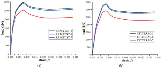
Figure 15.
Load–strain curve of the RRACFCST and the CSTCRRAC with different reinforcement rates. (a) Load–strain curve of RACFCST stub column. (b) Load–strain curves of CSTCRRAC stub columns.
Figure 16 schematically illustrates the influence of the reinforcement ratio on the specimens, with the abscissa representing the reinforcement rate of the specimens. It is evident that the bearing capacity increases with the rise in the reinforcement rate. Specifically, for the RRACFCST specimens, the one with the maximum reinforcement rate exhibited a 17.86% increase in strength compared to the specimen without a steel reinforcement cage; for the CSTCRRAC specimens, the one with the maximum reinforcement rate showed a 16.44% increase in strength relative to the specimen without a steel reinforcement cage.
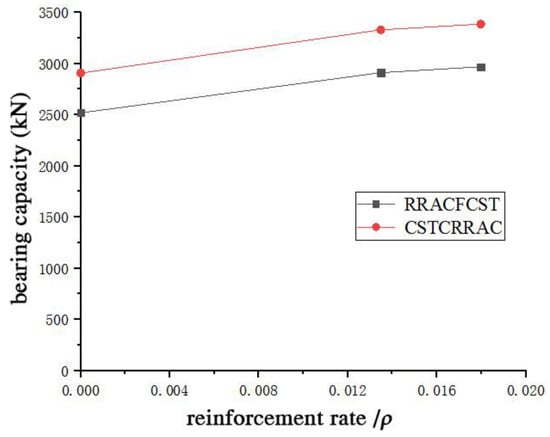
Figure 16.
Effect of reinforcement rate on bearing capacity.
4.5. Steel Tube Diameter–Thickness Ratio on the Ultimate Bearing Capacity
Figure 17 and Figure 18 present the load–strain curves and influence diagrams of confined circular steel tubular columns fabricated with recycled aggregate concrete (RRAC) under varying steel tube diameter-to-thickness ratios. As observed in Figure 18, the ultimate bearing capacity of these confined circular steel tubular columns decreases with an increase in the diameter-to-thickness ratio. At the maximum ratio, the RRACFCST specimens exhibit a 33.72% reduction in ultimate bearing capacity, while the CSTCRRAC specimens undergo a 33.62% reduction under the same maximum ratio. Additionally, the CSTCRRAC specimens show a 33.62% reduction in ultimate bearing capacity at the minimum ratio. This phenomenon can be attributed to the weakened restraining effect of the steel tube on RRAC as the diameter-to-thickness ratio increases, which in turn leads to insufficient strength improvement of RRAC and thus a decrease in the overall bearing capacity of the columns.
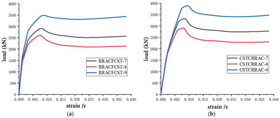
Figure 17.
Load–strain curve of the RRACFCST and the CSTCRRAC with different diameter-thickness ratio. (a) Load–strain curves of RRACFCST column. (b) Load–strain curves of CSTCRRAC column.
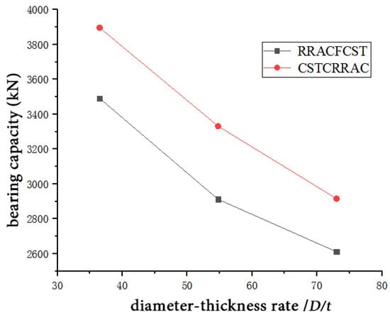
Figure 18.
Effect of diameter–thickness rate of steel tube on bearing capacity.
4.6. Practical Implication Discussions for Bridge Design
The findings of this study have significant implications for the design of sustainable bridge structures. The RRACFCST column offers a promising solution for bridge piers and other compression members due to its enhanced axial capacity, ductility, and environmental benefits.
- (I)
- Serviceability: The improved confinement effect and higher bearing capacity allow for reduced cross-sections or longer spans, improving aesthetic and functional design options. The stiffness and deformation characteristics observed also suggest better performance under service loads.
- (II)
- Durability: The dual confinement mechanism mitigates crack development and delays degradation, which is critical for bridges exposed to de-icing salts, moisture, and cyclic loading. The use of RAC with optimized replacement rates (e.g., 70%) further enhances long-term performance.
- (III)
- Fire Resistance: While not explicitly tested here, the concrete infill provides inherent fire protection to the steel tube, and the reinforcement cage adds redundancy. Future studies should quantify fire resistance, but existing research on CFST columns suggests favorable behavior.
5. Comparative Analysis
5.1. Comparison of Experimental, Simulated, and Formula Values of RACFECT and RRACFCST
In this study, two types of steel tubular members were selected for simulation analysis: reinforced concrete-filled steel tubular stub columns from reference [29] and recycled concrete-filled steel tubular stub columns from reference [30]. The material model was validated by comparing experimental values, bearing capacity-formula-calculated values, and simulation results. To date, research reports on axial compression tests of reinforced recycled aggregate concrete circular steel tubular columns remain limited. Consequently, this paper adopted the steel reinforcement cage parameters from specimen N32LS-C in reference [29] and the steel tube recycled concrete parameters from the specimen in reference [30] to investigate the axial compression behavior of steel tube-reinforced recycled concrete stub columns. Additionally, comparisons were made between the bearing capacity values derived from the proposed formula and the simulation results.
Table 6 presents a comparison among the calculation results of the derived bearing capacity formula, the finite element simulation results, and the experimental results of the stub columns. It is evident from Table 6 that the simulation values from reference [29] and reference [30] are in close agreement with the experimental values, with errors below 5%. This confirms the rationality of the material model, interface contact settings, and element type selection. When comparing the bearing capacity formula values with the experimental values, the errors of other comparisons were within 5%, indicating good consistency, except for specimens A2 and A4, which showed errors of 8% and 6%, respectively. Furthermore, when comparing the bearing capacity formula values with the simulation values, the errors for all specimens were within 5%, meeting the accuracy requirements. In addition, this paper compared the circular steel tube reinforced recycled concrete stub columns (specimen numbers A35, A36, A37, A38, and A39) with the steel tube recycled concrete stub columns from Reference [30] (specimen numbers A5, A6, A7, A8, and A9). The results show that the simulation values of the bearing capacity for reinforced recycled aggregate concrete circular steel tubular columns had an average increase of 10%, while the calculated values from the bearing capacity formula exhibited an average increase of 8%.
Table 6.
Comparison of test, simulation, and formula results of ultimate bearing capacity.
Based on the aforementioned comparative analysis, it is clear that the proposed compressive bearing capacity formula for reinforced recycled aggregate concrete steel tubular columns is also applicable to calculating the axial compressive bearing capacity of steel tube reinforced concrete stub columns and steel tube recycled aggregate concrete stub columns. The dual confinement effect of the steel tube and steel reinforcement cage on RAC led to an approximately 10% increase in the axial compressive bearing capacity of reinforced recycled aggregate concrete-filled steel tubular stub columns compared to recycled concrete-filled steel tube stub columns.
5.2. Comparison of the Formula Value of CSTCCRRAC with the Simulation Value
The RRACFCST stub column bears longitudinal loads directly through the outer steel tube. Before reaching the ultimate load, the steel tube undergoes compressive yielding, which impairs its ability to constrain the RAC. This weakens the confinement effect on the RAC and undermines the compressive stability of the stub column. To mitigate this issue, an investigation was carried out on the confinement effect of the circular steel tube on steel-reinforced recycled concrete stub columns by detaching the circular steel tube from the steel-reinforced recycled concrete in the upper and lower regions.
Table 7 presents a comparison between the axial compressive load capacity of circular steel tube-restrained reinforced recycled concrete stub columns and the corresponding simulation values. Except for specimens CSTCRRAC-1, CSTCRRAC-2, and CSTCRRAC-3, which exhibited errors of 6%, 6%, and 7%, respectively, the remaining comparison errors were within 5%, meeting the precision requirements. The derived formula demonstrates excellent practicality and is applicable to calculating the axial compressive load capacity of both circular steel tube-restrained reinforced concrete stub columns and circular steel tube-restrained recycled concrete stub columns.
Table 7.
Comparison of formula and simulation results for ultimate bearing capacity.
Similarly, parameter comparisons involving the steel tube’s diameter-to-thickness ratio, reinforcement ratio, and recycled coarse aggregate replacement rate reveal the following: the axial compressive capacity of circular steel tube-restrained reinforced recycled concrete stub columns decreases with an increase in the diameter-to-thickness ratio. In contrast, the incorporation of reinforcement cages enhances the confinement effect on the core RAC, thereby improving the axial compressive capacity of the stub columns. Notably, variations in the recycled coarse aggregate replacement rate have a minimal impact on the axial compressive capacity of such stub columns.
5.3. Comparison of the Formula Value of CSTCCRRAC and RRACFCST with the Simulated Value of Their Bearing Capacity
The distinct working mechanisms between circular steel tube-restrained reinforced recycled concrete and circular steel tube-reinforced recycled concrete lead to differences in various mechanical behaviors. In circular steel tube-reinforced recycled concrete, the outer steel tube remains connected at both ends; thus, when subjected to longitudinal loading, the steel tube yields prematurely and loses its restraining effect on the RAC, resulting in only a slight increase in the axial compressive capacity of the stub column. In contrast, circular steel tube-restrained reinforced recycled concrete does not bear longitudinal loads directly through its outer steel tube. Instead, it maintains a continuous restraining effect on the RAC, thereby exhibiting a higher bearing capacity than circular steel tube-reinforced recycled concrete. Table 8 presents a comparison of the axial compressive load capacities between these two types of stub columns.
Table 8.
Comparison of bearing capacity.
As shown in Table 8, the axial compressive capacity of circular steel tube-restrained reinforced recycled concrete stub columns exceeds that of circular steel tube-reinforced recycled concrete stub columns, with an 8% increase in the calculated values from the capacity formula and an average 13% increase in the simulated capacities. These results confirm that circular steel tube-restrained reinforced recycled concrete exhibits higher compressive capacity compared to circular steel tube-reinforced recycled concrete.
As listed in Table 6, Table 7 and Table 8, the generally strong agreement between the experimental, numerical, and theoretical results validates the proposed modeling approach and theoretical formula. The observed discrepancies, which were within 8%, can be attributed to several factors: (I) the idealized constitutive models for materials, particularly the simplified damage evolution of RAC; (II) the assumption of a constant friction coefficient at the steel-concrete interface, which may evolve under high stress; and (III) minor geometric imperfections in experimental specimens that are not captured in the idealized finite element model.
From a design perspective, these deviations are within the expected scatter for composite structures and are significantly smaller than the safety factors (e.g., resistance factors, φ, typically ranging from 0.75 to 0.9) prescribed in design codes such as AISC 360 [34], GB 50936 [35], and Eurocode 4 (EN 1994-1-1) [36]. Therefore, the accuracy of the proposed formula is deemed sufficient for predicting the nominal axial compressive capacity, with the application of standard code-mandated safety factors ensuring overall structural reliability. In summary, the consistent superiority of the CSTCRRAC system, especially with 100% RCA, validates the proposed mechanism; namely, the performance of RAC is profoundly influenced by the confinement scheme.
6. Conclusions
This study provides a comprehensive theoretical and numerical framework for evaluating the axial compressive behavior of RRACFCST columns. The derived formulas and validated FEM model offer direct practical value for bridge engineers seeking to adopt sustainable materials without compromising structural integrity. Some significant conclusions are obtained as follows:
- (1)
- The analysis of reinforced recycled aggregate concrete-filled circular steel tubular stub columns was conducted using limit analysis, the theory of ferrule, and the twin shear unified strength theory. A set of calculation methods for the bearing capacity of such stub columns was proposed, considering factors such as the diameter–thickness ratio of the steel tube, the constraint effect coefficient, the steel reinforcement ratio, and the replacement rate of recycled coarse aggregate. The calculated values were compared with the simulated values, demonstrating good agreement between them.
- (2)
- Finite element analysis of reinforced recycled aggregate concrete-filled steel tubular stub columns and reinforcement concrete-filled steel tubular stub columns ensured that the error between the two simulation results was controlled within 5%. This verification confirms the reliability of the material model, interface contact, and element type selection. Additionally, the finite element simulation results of reinforced recycled aggregate concrete-filled circular steel tubular stub columns were analyzed, indicating the suitability of this modeling approach for studying circular steel tube (confined) reinforced recycled concrete stub columns.
- (3)
- Building upon existing research on reinforced (confined) recycled aggregate concrete-filled circular steel tubular stub columns, the addition of a new steel reinforcement cage within the steel tube enhanced the bearing capacity. The specimen with the highest reinforcement ratio among the RRACFCST specimens exhibited a 17.86% increase in strength compared to the specimen without a steel reinforcement cage, while the CSTCRRAC specimen with the highest reinforcement ratio demonstrated a 16.44% increase in strength. The bearing capacity of tubular stub columns initially decreased and then increased as the replacement rate of coarse aggregate varied, with the maximum ultimate bearing capacity occurring at a 70% replacement rate.
- (4)
- Among the CSTCRRAC specimens, the one with a 100% replacement rate achieved the maximum ultimate bearing capacity, which was 13.3% higher compared to the maximum value of the RRACFCST specimen. An increase in the reinforcement ratio enhanced the restraining effect on the core RAC and correspondingly increased the bearing capacity of the tubular stub column. Conversely, an increase in the diameter–thickness ratio of the steel tube weakened the restraining effect on the RAC, leading to a decrease in the bearing capacity of the tubular stub column. At the maximum ratio of diameter-to-thickness, the RRACFCST specimens experienced a 33.72% reduction in ultimate bearing capacity, while the CSTCRRAC specimens encountered a 33.62% reduction. Similarly, the CSTCRRAC specimens exhibited a 33.62% reduction in ultimate bearing capacity at the minimum ratio.
- (5)
- The restraint stress expression for the steel reinforcement cage was provided. It was observed that the axial compression bearing capacity of reinforced recycled aggregate concrete-filled circular steel tubular stub columns, when equipped with steel reinforcement cages, was approximately 10% higher than that of their recycled aggregate concrete-filled circular steel tubular counterparts.
This study supports the use of RRACFCST columns in compression members like bridge piers, demonstrating benefits for serviceability and strength. However, these findings were derived from stub column tests under pure axial compression and do not address the behavior of slender members, long-term durability, or seismic performance. To enable full codification and widespread adoption, future work must therefore expand to include full-scale testing, and specifically investigate the effects of slenderness, cyclic seismic loading, and long-term environmental degradation.
Author Contributions
Methodology, D.L.; Software, W.Y.; Validation, F.W.; Resources, C.L.; Writing—original draft, F.W. and W.Y.; Writing—review & editing, Y.C.; Visualization, C.L.; Funding acquisition, D.L. All authors have read and agreed to the published version of the manuscript.
Funding
This work was supported by the Open Research Subject of State Key Laboratory of Bridge Safety and Resilience (Grant No. 2024SKLBSR-DW006), Tertiary Education Scientific research project of Guangzhou Municipal Education Bureau (2024312467).
Data Availability Statement
The original contributions presented in the study are included in the article, further inquiries can be directed to the corresponding author/s.
Conflicts of Interest
Author Yiqian Chen was employed by the company China Merchants Chongqing Communications Research & Design Institute Co., Ltd. The remaining authors declare that the research was conducted in the absence of any commercial or financial relationships that could be construed as a potential conflict of interest.
References
- Ikhine, I.V.; Rosti, F.; Hosseinpour, F.; Gopu, V.; Cooper, S., III. Experimental Study on the Strength Behavior of Concrete Reinforced with Cornhusk Fiber. Steps Civ. Constr. Environ. Eng. 2025, 3, 1–12. [Google Scholar]
- Jahami, A.; Younes, H.; Khatib, J. Enhancing Reinforced Concrete Beams: Investigating Steel Dust as a Cement Substitute. Infrastructures 2023, 8, 157. [Google Scholar] [CrossRef]
- Xiao, J.Z. Recycle Concrete; China Building Materials Industry Press: Beijing, China, 2008. [Google Scholar]
- Jang, H.; Kim, J.; Sicakova, A. Effect of aggregate size on recycled aggregate concrete under equivalent mortar volume mix design. Appl. Sci. 2021, 11, 11274. [Google Scholar] [CrossRef]
- Bian, J.W.; Zhang, W.B.; Shen, Z.Z.; Li, S.; Chen, Z. Analysis and optimization of mechanical properties of recycled concrete based on aggregate characteristics. Sci. Eng. Compos. Mater. 2021, 28, 516–527. [Google Scholar] [CrossRef]
- Liang, C.F.; Ma, H.W.; Pan, Y.Q.; Ma, Z.; Duan, Z.; He, Z. Chloride permeability and the caused steel corrosion in the concrete with carbonated recycled aggregate. Constr. Build. Mater. 2019, 218, 506–518. [Google Scholar] [CrossRef]
- Albuquerque, A.; Pacheco, J.; de Brito, J. Reliability-based recommendations for EN1992 carbonation cover the design of concrete with coarse recycled concrete aggregates. Struct. Concr. 2022, 23, 1873–1889. [Google Scholar] [CrossRef]
- Zheng, C.L.; Li, S.X.; Hou, Y.F.; Jin, B. Frost resistance of fiber-reinforced self-compacting recycled concrete. Rev. Adv. Mater. Sci. 2022, 61, 711–725. [Google Scholar] [CrossRef]
- Kim, J. Influence of quality of recycled aggregates on the mechanical properties of recycled aggregate concretes An overview. Constr. Build. Mater. 2022, 328, 127071. [Google Scholar] [CrossRef]
- Sasanipour, H.; Aslani, F. Durability properties evaluation of self-compacting concrete prepared with waste fine and coarse recycled concrete aggregates. Constr. Build. Mater. 2020, 236, 117540. [Google Scholar] [CrossRef]
- Ellobody, E.; Young, B.; Lam, D. Behaviour of normal and high strength concrete-filled compact steel tube circular stub columns. J. Constr. Steel Res. 2006, 62, 706–715. [Google Scholar] [CrossRef]
- Mahmoud, A.A.; EI-Sayed, A.A.; Aboraya, A.M.; Fathy, I.N.; Abouelnour, M.A.; Elfakharany, M.E.; Fattouh, M.S.; Alahmer, A.E.; Nabil, I.M. Influence of elevated temperature exposure on the residual compressive strength and radiation shielding efficiency of ordinary concrete incorporating granodiorite and ceramic powders. Sci. Rep. 2025, 15, 3572. [Google Scholar] [CrossRef]
- Mahmoud, A.A.; EI-Sayed, A.A.; Aboraya, A.M.; Fathy, I.N.; Zygouris, N.; Sadollah, A.; Agwa, I.S.; Tayeh, B.A.; Asteris, P.G. Synergizing machine learning and experimental analysis to predict post-heating compressive strength in waste concrete. Struct. Concr. 2025, 26, 2916–2950. [Google Scholar] [CrossRef]
- Liu, Y.C.; Lyu, F.; Ding, F.X.; Wang, E.; Xu, Y.; Yuan, T.; Deng, C.; Luo, C. Numerical study on confinement effect and efficiency of concentrically loaded RACFRST stub columns. Front. Mater. 2021, 8, 630774. [Google Scholar] [CrossRef]
- Han, L.H.; Xu, C.Y.; Hou, C. Axial compression and bond behavior of recycled aggregate concrete-filled stainless steel tubular stub columns. Eng. Struct. 2022, 262, 114306. [Google Scholar] [CrossRef]
- Tam, V.W.Y.; Tao, Z.; Evangelista, A. Performance of recycled aggregate concrete filled steel tubular (RACFST) stub columns with an expansive agent. Constr. Build. Mater. 2021, 272, 121627. [Google Scholar] [CrossRef]
- Zhou, J.; Chen, Z.P.; Zhou, C.H. Residual behavior of SRRAC beam and column after exposure to high temperatures. Steel Compos. Struct. 2022, 45, 369–388. [Google Scholar]
- Xu, J.J.; Chen, Z.P.; Zhao, X.Y.; Demartino, C.; Ozbakkaloglu, T.; Xue, J.Y. Seismic performance of circular recycled aggregate concrete-filled steel tubular columns: FEM modeling and sensitivity analysis. Thin-Walled Struct. 2019, 141, 509–525. [Google Scholar] [CrossRef]
- Ke, X.J.; Xu, D.Y.; Cai, M. Experimental and numerical study on the eccentric compressive performance of RAC-encased RACFST composite columns. Eng. Struct. 2020, 224, 111227. [Google Scholar] [CrossRef]
- Yang, Y.F.; Hou, C.; Liu, M. Tests and numerical simulation of rectangular RACFST stub columns under concentric compression. Structures 2020, 27, 396–410. [Google Scholar] [CrossRef]
- Wang, Y.Y.; Chen, J.; Geng, Y. Testing and analysis of axially loaded normal-strength recycled aggregate concrete-filled steel tubular stub columns. Eng. Struct. 2015, 86, 192–212. [Google Scholar] [CrossRef]
- Lyu, W.Q.; Han, L.H.; Hou, C. Axial compressive behavior and design calculations on recycled aggregate concrete-filled steel tubular (RAC-FST) stub columns. Eng. Struct. 2021, 241, 112452. [Google Scholar] [CrossRef]
- Cai, S.H. Modern Steel Tube Concrete Structures; China Communications Press: Beijing, China, 2003. [Google Scholar]
- Ao, W.G.; Wang, X.D.; Zhang, H.Y. Elastic-plastic limit analysis of the combined thick-walled cylinder based on the unified strength theory. Int. J. Innov. Comput. Inf. Control 2022, 18, 183–197. [Google Scholar]
- Mander, J.G.; Priestley, M.J.N.; Park, R. Theoretical stress-strain model for confined concrete. J. Struct. Eng. 1988, 114, 1804–1826. [Google Scholar] [CrossRef]
- Xiao, J.Z. Recycled Aggregate Concrete Structures; Springer Press: Berlin, Germany, 2018. [Google Scholar]
- Gaurav, G.; Kotoky, N.; Jittin, V.; Bahurudeen, A. Performance assessment of recycled aggregate concrete and its variability. Struct. Concr. 2023, 24, 6239–6250. [Google Scholar] [CrossRef]
- Peng, Y.L.; Gong, A.M.; Sun, H.Y. Experimental study on the variation law of elastic modulus of recycled aggregate concrete. Water Conserv. Sci. Technol. Econ. 2011, 17, 8–12. [Google Scholar]
- Luo, J. Research on Mechanical Properties of Reinforced Concrete-Filled Steel Tubular Members; Shenyang University of Technology: Shenyang, China, 2012. [Google Scholar]
- Chen, Z.P.; Zhang, S.Q.; Wang, N. Experimental study and theoretical analysis on axial compress capacity of recycled aggregate concrete-filled circle steel tube stub column. Eng. Mech. 2013, 30, 107–114. [Google Scholar]
- Xiao, J.Z.; Yang, J.; Huang, Y.J.; Wang, Z. Experimental study on recycled concrete confined by steel tube under axial compression. J. Build. Struct. 2011, 32, 92–98. [Google Scholar]
- Poon, C.S.; Kou, S.C.; Lam, L. Influence of recycled aggregate on slump and bleeding of fresh concrete. Mater. Struct. 2007, 40, 981–988. [Google Scholar] [CrossRef]
- Bentz, D.P. Internal curing of high-performance blended cement mortars. ACI Mater. J. 2007, 106, 87. [Google Scholar]
- ACI 318-11; Building Code Requirements for Structural Concrete and Commentary. American Concrete Institute: Detroit, MI, USA, 2011.
- GB 50936-2014; Code for Design of Steel and Concrete Composite Structures. Ministry of Housing and Urban-Rural Development of the People’s Republic of China: Beijing, China, 2014.
- EN 1994-1-1; Design of Composite Steel and Concrete Structures—Part 1-1: General Rules and Rules for Buildings. European Committee for Standardization: Brussels, Belgium, 2004.
Disclaimer/Publisher’s Note: The statements, opinions and data contained in all publications are solely those of the individual author(s) and contributor(s) and not of MDPI and/or the editor(s). MDPI and/or the editor(s) disclaim responsibility for any injury to people or property resulting from any ideas, methods, instructions or products referred to in the content. |
© 2025 by the authors. Licensee MDPI, Basel, Switzerland. This article is an open access article distributed under the terms and conditions of the Creative Commons Attribution (CC BY) license (https://creativecommons.org/licenses/by/4.0/).