Abstract
Rammed earth (RE) dwellings are characterized by accessible materials, low cost, and environmental sustainability. However, their poor seismic resistance limits their application. To address this issue, three conventional technical approaches have been developed: (1) adding cement to improve strength; (2) improving structural integrity using reinforced concrete ring beams and columns; and (3) embedding vertical steel bars in order to provide resistance against horizontal seismic actions. While effective, these methods rely on energy-intensive materials with high carbon emissions. In this study, we analyze the seismic damage characteristics and construction mechanisms of RE walls. The results reveal that the horizontal joints in RE walls significantly weaken their resistance to horizontal seismic actions. To mitigate this, three types of undulating joints are proposed and six specimens tested. The maximum horizontal loads of the specimens with local subsidence-type joints are 132.44 kN and 135.41 kN, respectively, which are approximately 50% higher than specimens with horizontal joints, whose maximum horizontal loads are 80.7 kN and 85.83 kN, respectively, while the maximum horizontal loads of the specimens with horizontally concatenated gentle arc-type joints are 151.17 kN and 173.58 kN, respectively, and they exhibit nearly double the shear capacity of the specimens with horizontal joints. Building on these findings and test results, we also include recommendations for integrating elegant RE wall texture design with seismic-resistant undulating joint technology.
1. Introduction
Earthen architecture is globally widespread, housing approximately 30% of the world’s population [1]. In China, RE construction boasts a profound history [2]. Ancient Chinese poetic texts from around 1000 BC vividly documented the large-scale construction of earthen settlements for imperial capitals [3]. Descriptions of RE techniques also appear in the house-building ritual chants of ethnic minorities in southwestern China [4]. Among extant traditional rural dwellings, earthen materials remain the most prevalent wall-building resource. The cultural DNA of earthen architecture flows through the vast heritage of Chinese traditional construction, persisting to this day. Moreover, RE has significant potential to address resource and environmental crises [5].
RE walls have multiple advantages, including local material sourcing, straightforward construction, and low-cost implementation. In rural environments, erecting RE structures necessitates community-organized collaborative efforts. Notably, Tibetan regions in the Yunnan and Sichuan provinces of China have preserved the traditional practice of collective ramming chants—in which dozens to hundreds of local people participate during wall construction—a cultural practice that profoundly strengthens community cohesion and fosters social harmony through shared building activities.
Traditional RE walls have relatively low structural strength and are primarily employed in low-rise building construction [6]. Even in such height-limited structures, historical seismic events have demonstrated that collapses of traditional earth buildings have been responsible for numerous rural casualties and significant property damage [7,8]. In the interests of enhancing seismic resistance, research institutions have developed multiple seismic resistance technologies that target RE structures [9,10,11,12]. While these innovations have moderately improved anti-seismic capabilities, they still fall short of meeting the necessary requirements for cost-effectiveness, construction simplicity, and ease of promotion that will facilitate their widespread rural adoption.
2. Methodology
The primary objective of this study is to investigate the shear performance of RE walls with undulating joints through comparative testing. To achieve this goal, the following step-by-step methodology was developed and implemented:
- Step 1: Analysis of Typical Seismic Damage Patterns and Shear Sliding Failure Mechanisms in RE Walls.Starting with the construction features of RE walls, this study examines the formation of horizontal joints and their adverse effects on seismic performance. By combining photographic evidence of seismic damage in RE buildings, two typical types of horizontal joints were identified: predictable and unpredictable slip joints. Although incorporating vertical reinforcement, ring beams, and structural columns improves overall integrity, the shear capacity of the RE materials remains underutilized. Targeted techniques are therefore needed to enhance shear performance while reducing the use of high-carbon materials such as cement, steel, and concrete.
- Step 2: Implementation of Undulating Joints in RE Walls.To address the inherent deficiency caused by the parallelism between horizontal seismic action and the traditional horizontal ramming joints of RE walls, a partial subsided construction method was introduced. This technique replaces continuous horizontal joint lines with undulating joints, thereby redirecting potential slip failures along horizontal planes into full or partial material shear failures—effectively enhancing the overall shear resistance of the RE walls. Furthermore, with consideration for construction efficiency, three distinct types of partially subsided joints were proposed: local subsidence-type joints, oblique zigzag-type joints, and horizontally concatenated gentle arc-type joints.
- Step 3: Comparative Shear Testing of RE Walls with Varied Joint Typologies.In accordance with the requirement that the average compressive strength of 150 mm cubic rammed earth specimens must exceed 4 MPa, the soil mixture for the wall specimens was first determined. Using a consistent soil mixture ratio and the same construction techniques, three groups of RE walls were fabricated, each containing two walls. The control group featured conventional horizontal joints, while the other two groups incorporated local subsidence-type joints and horizontally concatenated gentle arc-type joints, respectively. A vertical load of 100 kN was applied to each wall, then monotonic tests were carried out. The experimental results enabled a comparative analysis of the shear capacity, ultimate state, and ductility of the walls with different joint configurations.
- Step 4: Integration of Esthetic Expression and Seismic Resistance Technology for Undulating Jointed RE Walls.This phase examines the harmonious integration of artistic esthetics and structural performance in RE walls incorporating undulating joints. It addresses potential conflicts between esthetic goals and structural requirements, proposing practical solutions to achieve both the visual continuity and seismic resilience of the RE wall.
- Step 5: Synthesis of Findings and Preliminary Conclusions.Based on the experimental and analytical results, a preliminary framework for understanding the seismic resistance of RE walls with undulating joints has been established. This synthesis integrates key findings to formulate conclusions pertaining to the structural performance, practical feasibility, and potential applications of the proposed technique.
3. Problem Analysis and Current Technologies
3.1. Typical Seismic Damage Patterns in RE Walls
Under horizontal seismic actions, the issues exhibited by RE walls can be divided into two primary categories [13]. The first is strength-related failures. Due to the low tensile strength of RE, diagonal or cross-diagonal cracks at 45° to the horizontal plane develop on the wall surface during earthquakes. Insufficient shear resistance leads to shear failure, characterized by in-plane horizontal sliding between wall segments. The second concern is stability-related failures, in which out-of-plane instability manifests as localized or overall collapse of the wall. This study focuses on the in-plane shear resistance of RE walls; out-of-plane stability will be addressed separately.
3.2. Analysis of Shear Sliding Failure Mechanisms in RE Walls
The sliding displacement of RE walls refers to the relative displacement that occurs at weight-bearing surfaces or material weakness planes under horizontal seismic action. The in-plane shear failure of RE walls is closely related to the techniques used during their construction. When temporary formworks are erected to confine the soil during compaction, loose moist soil (15–25 cm thick) is deposited within the formwork, then manual or mechanical tamping is implemented to create a dense soil layer with a compacted upper section and less consolidated base. The complete wall structure is formed through sequential layering of compacted soil units. The interface between individual compacted layers (construction joints) and the layered soil units (base materials) creates the distinctive RE texture (Figure 1).
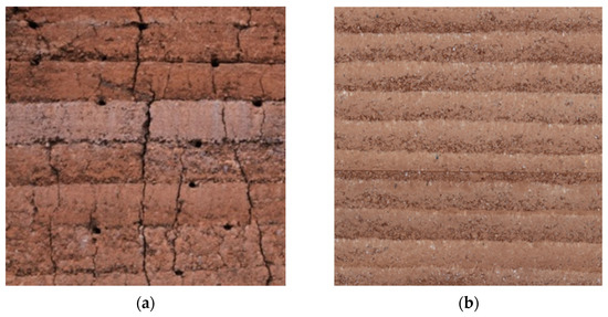
Figure 1.
Texture of RE wall. (a) Yunnan vernacular RE wall; (b) modern RE wall.
3.2.1. Classification of Slip Joints in RE Walls
Predictable slip joints occur at interfaces between RE walls and structural supports (e.g., foundation tops, floor slabs), where weak bonding exists between RE and materials such as concrete or timber components (Figure 2). Under horizontal seismic actions, shear failure develops at these junctions due to material incompatibility, leading to relative sliding with identifiable locations.
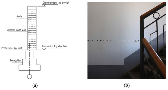
Figure 2.
Predictable slip joint. (a) Section drawing of a predictable slip joint; (b) slippage of an RE wall along the floor slab caused by horizontal seismic actions.
The amount of predictable slip surfaces is limited, and their locations are clearly defined, making mitigation relatively manageable. Surface roughening and shear key installation can be used to enhance the shear resistance capacity of interfaces. Surface roughening indicates that the bonding interface is mechanically roughened by chiseling to improve interlocking between materials. Shear keys are embedded at critical interfaces using materials such as brick, stone, timber, steel, or concrete (Figure 3), which act as mechanical interlocks to resist horizontal displacement in response to seismic actions.
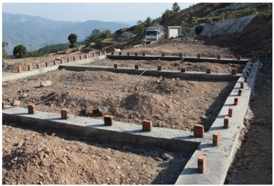
Figure 3.
Anti-sliding key.
The second type of slip joint is unpredictable slip joints. Numerous horizontal joints exist along the vertical profile of RE walls due to layered construction practices. These interfaces exhibit low shear strength if interlayer bonding is inadequately addressed during compaction. Poor bonding may occur due to uneven moisture distribution, rushed compaction cycles, or insufficient material gradation. Even laboratory-controlled RE specimens demonstrate shear failure along these joints, confirming their status as structural weak points (Figure 4).
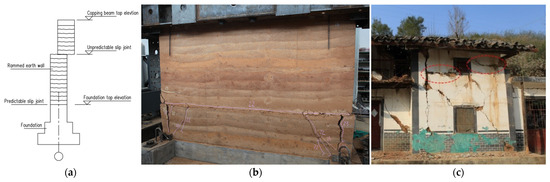
Figure 4.
Unpredictable slip surfaces. (a) A diagram showing a section of an unpredicted slid joint; (b) an unpredicted horizon slid joint created in a laboratory setting; (c) examples of seismic damage resulting from unpredictable slip joints.
Due to economic and technical constraints, RE walls in southwest China are typically constructed using small formwork panels for segmented ramming (Figure 5). This method inherently generates two types of unpredictable joints.
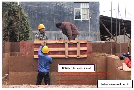
Figure 5.
A unit of formwork.
Inter-formwork joints form between compacted soil layers within a single formwork module. Continuous ramming processes generally ensure better interlayer bonding, whereas weakness may be caused by unplanned interruptions (e.g., rainfall, power outages, labor gaps), which can degrade the bonds in horizontal joints. Figure 4c illustrated an unpredicted horizontal slid joint on top of the sill on the second floor, for the horizontal seismic actions of the corner wall beside the window are smaller than the corner wall beside the window on the first floor. The other kind of horizontal joints are between-formwork joints, which occur at interfaces between upper and lower formwork modules. Prolonged exposure during formwork disassembly and assembly or work breaks often weakens the bonds, which risks affecting the quality. The weakness of these two types of joints could be visualized as block-like fractures that form along joints during rammed wall demolition (Figure 6).
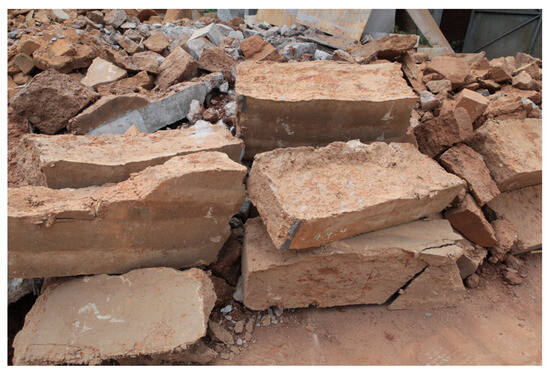
Figure 6.
Blocks of a demolished RE wall.
3.2.2. Enhancement Strategies for Improving the Shear Resistance of RE Walls
The first strategy for enhancing the shear resistance of RE walls is cement stabilization. Incorporating 5–15% cement into soil mixtures could increase the compressive strength of RE to 3–10 MPa [14,15,16,17], indirectly improving the shear capacity for seismic resistance. High cement content compromises the ecological and low-carbon advantages of RE. The second strategy is shearing key installation at joints, in which prefabricated shear keys are embedded at RE layer interfaces to restrict relative sliding [18,19]. The third strategy is structural integrity reinforcement, in which reinforced concrete top beams and columns (Figure 7) are integrated to form a rigid framework, improving the overall stability of the wall [20]. Vertical reinforcement systems can also be employed to enhance lateral load-bearing capacity; this involves using steel bars, which are vertically placed within walls [21]. Integration of the above-mentioned methods is common practice for improving the shear capacity of RE walls.
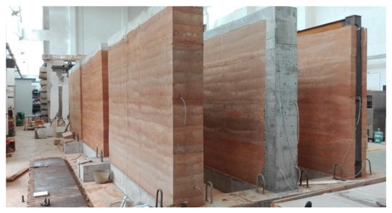
Figure 7.
RE wall with top beam and steel cube or concrete structural columns.
We drew three conclusions based on the above construction analysis: Firstly, the vertical compressive strength of RE walls remains unaffected by interlayer weak planes, but the shear resistance at layer interfaces may be significantly lower than the base material’s intrinsic shear capacity. The second is that optimizing soil mixtures or refining construction techniques (e.g., cement stabilization) fails to enhance shear performance unless interlayer bonding is specifically strengthened. Structural integrity measures such as top beams, structural columns, and steel bars embedded in walls improve the overall integrity of the wall but do not fully address interlayer sliding or utilize the base material’s inherent shear strength.
4. RE Walls with Undulating Joints and Technical Implementation
Due to the alignment of horizontal seismic actions parallel to RE wall joints, the actions induce shear failure along horizontal interfaces, resulting in interlayer sliding—an inherent flaw of traditional RE construction. To address this limitation, technical solutions focus on modifying joint geometry to redirect shear paths across compacted layers, thereby activating the shear resistance of the base material.
4.1. Proposal of RE Wall Construction with Undulating Joints
Vertical joints perpendicular to horizontal seismic actions theoretically maximize shear resistance by aligning shear paths across compacted layers. However, vertical joints hinder soil layering and horizontal compaction, complicating on-site ramming. Additionally, vertical joints divide walls into slender soil columns, increasing their risk of buckling under vertical loads and reducing their load-bearing capacity. In light of this, horizontal soil layering remains standard practice due to its operational simplicity and compatibility with manual/mechanical ramming techniques. In order to achieve a balance between seismic resilience and constructability, localized undulating joints that maintain predominantly horizontal alignment were developed.
4.2. Morphological Deduction of Undulating Joints and Low-Tech Implementation
In so-called undulating joints, the joint line oscillates up and down along a horizontal line. Depending on the different requirements for the seismic performance of RE walls, it can take several typical forms. The first is local subsidence-type joints. Following the completion of an RE layer, a horizontally aligned joint forms at the upper surface. At this stage, localized secondary ramming is performed using a customized rammer to induce multi-point subsidence along the horizontal joint line (Figure 8). Subsequent placement and compaction of the overlying soil layer result in the formation of a local subsidence-type joint line, which is characterized by a gear-like profile. The gear-like interlocking mechanism generated by the subsidence geometry reinforces the shear capacity and integrity of the stratified RE system.
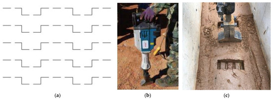
Figure 8.
A local subsidence-type joint. (a) A drawing of a local subsidence-type joint line. (b) A customized rammer. (c) An example of a local subsidence-type joint line.
The oblique zigzag-type joint is geometrically defined by the absence of horizontal and vertical segments. Two distinct implementation methodologies are employed to achieve this configuration. There are tool-driven fabrication and varying thickness construction. Tool-driven fabrication involves utilizing a wedge-shaped rammer with a narrow, ax-like working edge for secondary compaction on pre-formed horizontal joints. When zero-spaced V-shaped grooves are sequentially impressed during this process, a periodic oblique zigzag pattern emerges through controlled interfacial deformation. This method ensures geometric regularity that is optimized for structural interlocking efficiency. Thickness-modulated construction is a method in which the thickness of soil layers is strategically varied prior to compaction, and differential densification produces undulating interfaces with adaptive zigzag morphologies (Figure 9). The resultant joint lines exhibit enhanced fluidity in their spatial arrangement, demonstrating compatibility with architectural esthetics through organic integration into RE textures.
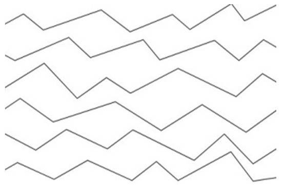
Figure 9.
An oblique zigzag-type joint.
Subsidence-type joints and oblique zigzag-type joints exhibit inherent structural vulnerabilities due to their acute angular geometries. Under seismic actions, concentrated stress at angular intersections induces localized material failure, leading to progressive structural deactivation of adjacent RE substrates. These geometric discontinuities act as stress risers, compromising load redistribution efficiency and accelerating crack nucleation. In contrast, horizontally concatenated gentle arc-type joints are characterized by horizontally concatenated gentle arcs that form through controlled thickness modulation of compacted soil layers (Figure 10). The absence of abrupt angular transitions eliminates the stress concentration phenomena observed in local subsidence/zigzag joints, enabling homogeneous stress dissipation along curvilinear interfaces. The rhythmic wave patterns (typically 60 mm amplitude) facilitate novel textural expressions while maintaining structural integrity, demonstrating compatibility with contemporary architectural design paradigms (Figure 10).
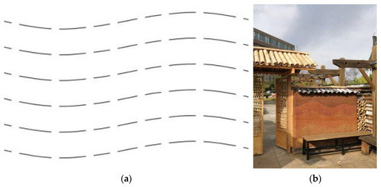
Figure 10.
Horizontally concatenated gentle arc joints. (a) Geometric shape. (b) Practical case.
4.3. Auxiliary Seismic-Resistant Measures for RE Walls with Undulating Joints
Both oblique zigzag-type joints and horizontally concatenated gentle arc-type joints are designed to have gentle geometries that facilitate ramming operations. However, when exposed to intense horizontal seismic actions, these joints may experience interfacial sliding displacement. If the RE wall lacks sufficient vertical load (e.g., enclosure walls), such sliding can escalate into slide-induced uplift, bypassing the material’s shear resistance and compromising structural stability. Load-bearing walls are subjected to higher imposed vertical loads (e.g., floor/roof loads in addition to self-weight), providing inherent uplift-resistance capacity. In contrast, enclosure walls rely solely on self-weight, exhibiting lower sliding resistance and heightened uplift risks when a strong earthquake occurs. To ensure seismic actions are transferred through material shear resistance rather than joint slippage, undulating joint RE walls require vertical displacement constraints. These constraints are implemented via three integrated components combined with vertical restraint rebars that cross undulating joints to anchor sliding interfaces, tensioned spring dampers with pre-stressed springs providing dynamic clamping force to suppress uplift, and reinforced concrete top beams to distribute restraint forces uniformly (Figure 11a).
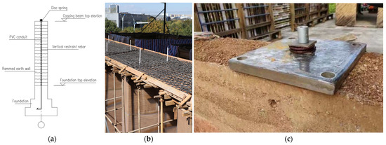
Figure 11.
Vertical restraint of earth wall. (a) Drawing of a section of the vertical reinforcement construction of RE walls; (b) construction involving vertical restraining reinforcement in an RE wall; (c) a sample of a disk spring.
Vertical restraint rebars are anchored at the base of the foundation, vertically penetrate the entire wall height, and are secured at the top with capping beams. Axial tension is applied via tensioned springs to maintain pre-stress. While conventional vertical reinforcement (e.g., steel bars) is widely used to enhance out-of-plane overtrenching resistance, field measurements reveal that during ramming operations, continuous downward compaction forces and vertical shrinkage of the rammed wall subject these bars to compressive forces. The restraint system operates by pre-tensioning the rebars to impose additional vertical confinement pressure on the RE wall. This counteracts horizontal seismic-induced uplift along undulating joint interfaces. Efficient tension transfer across the wall height must be maintained due to the stochastic nature of potential sliding surfaces. To mitigate tension loss caused by ramming-induced compression, restraint rebars are sleeved within steel tubes or high-strength PVC conduits, decoupling them from the surrounding compacted soil (Figure 11a,b). Steel bars are protected from the compressive force caused by earth ramming, ensuring that they achieve predictable tensile performance. Disk springs are used for their compact profile, as they save space during installation. Each restraint rebar passes through the spring’s central bore, and then axial pre-tension is applied by tightening nuts to compress the springs, thereby adding tension to the rebars (Figure 11c). The capping beam uniformly distributes the compressive forces from the disk springs, preventing localized overstressing of the RE wall’s top surface. Ring beams can serve dual roles, also acting as capping beams when structurally integrated.
Based on Coulomb’s law [22], for a given soil type, a higher level of normal stress (σ) on the shear plane increases the shear strength (τ). Vertical restraint rebars apply additional vertical pressure to the RE wall, instead of increasing vertical stress by the greater gravity loads, which in turn intensify the seismic actions of the walls [23]. This elevated σ amplifies the wall’s inherent shear capacity, reducing joint slippage risks under seismic action.
5. Comparative Test Studies of Undulating Jointed RE Walls
To verify the seismic effectiveness of undulating joint technology in RE walls, shear tests of six rammed walls were conducted. Experiments designed to evaluate the shear resistance of RE walls with horizontal, locally subsided, and horizontally concatenated gentle arc-type joint profiles were performed. By evaluating these configurations, this study verifies the effectiveness of undulating joints in enhancing shear capacity, providing scientific evidence to improve the seismic resilience of RE structures.
5.1. Introduction to Experimental Models
The RE wall specimens measure 1.2 m (length) × 0.8 m (height) × 0.35 m (thickness). Two specimens were prepared for each joint type, resulting in a total of six test specimens. The soil mixture comprised clay–stone chips—10 mm crushed stone in a 3:5:2 mass ratio (Figure 12)—with 5% Portland cement type 32.5 R stabilization. Water content: 9–12%. Each soil layer was compacted to approximately 100 mm after ramming with a pneumatic rammer.
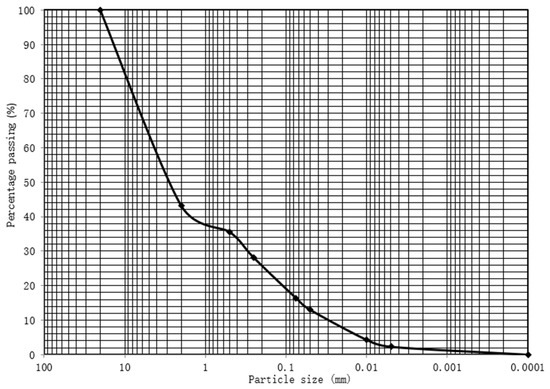
Figure 12.
Particle size distribution of soil final mix.
The scale effects on the experimental shear capability are a critical parameter influencing the RE walls. For the objective of the experiment, which is to test the shear capacity, specimens with a low height/length ratio of 0.8/1.2 were built. Ref. [23] suggests specimens with dimensions of 1000 mm × 900 mm × 200 mm for shear tests with a low height/thickness ratio of 0.9/1.0. The authors of [24] compiled 125 wall shear tests and suggested that the minimum cross-sectional area of the specimen should be more than 0.5 m2 to ensure the small-scale direct shear test results align with the realistic structure behavior of full-scale RE walls. If the cross-sectional area of the specimen is less than 0.5 m2, amplification factors are 3.4–3.8 for RE walls.
For ease of construction, the spacing of one subsidence zone of the subsidence joint RE walls was 400 mm, with the following dimensions: 150 mm (length) × 50 mm (depth). The second RE wall has 4 subsidences with a total width of 300, which is the same as the first specimen. For horizontally concatenated gentle arc-type joint RE walls, the wavelength was 400 mm, whereas the amplitude was 60 mm. All six specimens were constructed by the same team using identical techniques to ensure consistency (Figure 13). The final soil mix was placed into a formwork by layers of 15 cm-thick and then compacted to 10 cm-thick by using a pneumatic rammer to form the specimens. Specimens were cured for 30 days. Based on a 6 m high, two-story RE load-bearing residential structure, a vertical load of 100 kN was applied to the top of each specimen [25]. The horizontal seismic action is 22.9 kN [26] in the PGA 0.2 g level region. The shear capacity of the specimen should be no less than 87.02 kN.

Figure 13.
Specimens ready for test.
Prior to ramming the earth walls, five cubical RE specimens (150 mm per side) were prepared using distinct mix ratios. The soil mixture, which was the same as the RE wall specimens, was placed into a formwork in 15 cm-thick layers and then compacted to 10 cm-thick layers using a pneumatic rammer to form the specimens. Specimens were cured for 30 days. The average compressive strength of cubical RE specimens was 4.0 MPa (Figure 14) [16], with a coefficient of variation of 7.8%. The results of the compressive strength tests are summarized in Table 1.
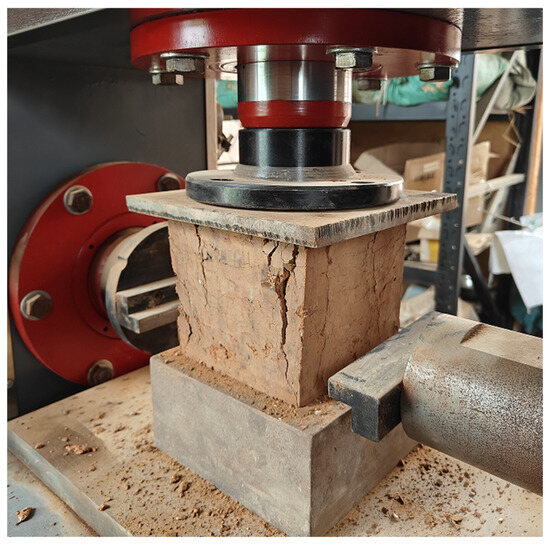
Figure 14.
Destructive compressive strength test of RE cube samples.

Table 1.
Mean compressive strength of tested cube samples.
5.2. Test Plan and Test Results
The monotonic test was conducted in three groups (Figure 15): Group 1: horizontally jointed RE walls (specimen IDs: EC-H1, EC-H2); Group 2: locally subsided jointed RE walls (specimen IDs: EC-Z1, EC-Z2); Group 3: horizontally concatenated gentle arc-type jointed RE walls (specimen IDs: EC-A1, EC-A2). Vertical loads were applied via hydraulic jacks, while horizontal loads were imposed by a 25-ton electro-hydraulic servo actuator. The test loading setup and instrumentation layout are illustrated in Figure 16. The results of the monotonic tests are summarized in Table 2 and Figure 17.
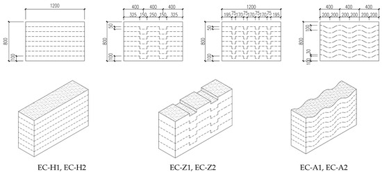
Figure 15.
Shear test RE wall axonometric drawing and size.
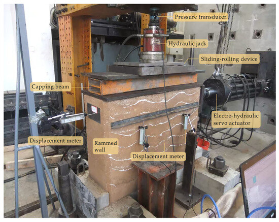
Figure 16.
Loading device and measuring point layout.
Table 2.
Synthesis of the results obtained.

Figure 17.
Load-deformation diagram of the RE wall specimens. (a) Horizontal joint RE wall specimens; (b) local subsidence joint RE wall specimens; (c) horizontally concatenated gentle arc-type joint RE wall specimens.
5.3. Analysis of Crack Pattern and Vmax Test Results
As observed from the failure cracks in the RE walls in Figure 18a, the contour of the failure cracks in the horizontally jointed RE walls aligns precisely with the horizontal joint line. This indicates that, under horizontal thrust, the walls underwent sliding along the joint line, while the shear resistance of the matrix material remained unused. The failure mechanism is, fundamentally, a sliding failure along the weak interfacial plane. The two horizontally jointed RE walls sustained maximum horizontal thrusts of 80.7 kN and 85.83 kN, respectively.
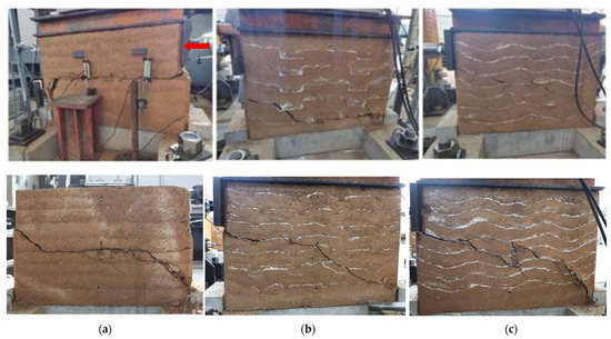
Figure 18.
Failed specimens after shear capacity test. (a) Horizontal joint RE wall specimens; (b) local subsidence-type joint RE wall specimens; (c) horizontally concatenated gentle arc-type joint RE wall specimens. Note: Unless otherwise specified, the thrust acts from left to right.
As observed from the failure cracks in the RE walls in Figure 18b, the failure patterns of the locally subsided jointed RE walls exhibit two distinct characteristics, as described below: Inclined crack segments span two adjacent joint lines, indicating that the shear strength of the matrix material is fully utilized, and horizontal crack segments partially penetrate the matrix material, suggesting that shear failure occurred within the matrix itself. This means that partial shear failure spread through the matrix (evidenced by cracks deviating from interface markers), where the shear resistance of the matrix material was mobilized. The remainder of the failure crack aligns precisely with the horizontal joint line where the shear resistance of the matrix material remained unutilized. The two locally subsided jointed RE walls sustained maximum horizontal thrusts of 132.44 kN and 135.41 kN, respectively.
As observed from the failure cracks in the RE walls in Figure 18c, the cracks traversed multiple joint lines and exhibited an overall inclined morphology. The overlapping range between cracks and interface marker lines was minimal, indicating that the primary failure mechanism was shear failure within the matrix material, where the shear resistance of the matrix was fully mobilized. The two horizontally concatenated gentle arc-type jointed RE walls sustained maximum horizontal thrusts of 151.17 kN and 173.58 kN, respectively.
As mentioned in Section 5.1, the shear capacity of a specimen should be no less than 87.02 kN to satisfy the seismic resistance in a PGA 0.2 g level region. The locally subsided jointed specimens and horizontally concatenated gentle arc-type jointed specimens can satisfy this seismic-resistant demand.
In summary, in RE walls with an identical material composition, structural configuration, and cross-sectional dimensions, locally subsided jointed walls exhibit a 61% increase in shear capacity compared to horizontally jointed walls, while horizontally concatenated gentle arc-type jointed walls demonstrate a 95.2% enhancement. Replacing conventional horizontal joints with horizontally concatenated gentle arc-type joints approximately almost doubles the shear capacity (Table 2).
The above analysis indicates that horizontally jointed RE walls are prone to sliding failure along weak interfaces under horizontal seismic actions, where the shear strength of the matrix material remains underutilized. In such cases, increasing the compressive strength of the rammed wall does not significantly enhance its shear capacity. Compared to Reference [16], which requires a compressive strength of at least 4 MPa for an RE cube, References [27,28] suggest that for low-rise buildings, 1.5–2.0 MPa may be sufficient. Although this lower range is not currently endorsed by design codes worldwide, this study provides a pathway for further research of such lower-strength RE walls used for load-bearing structures, which would reduce the cement content in the RE walls’ soil mixture.
5.4. Discussion of Limit States and Ductility of RE Walls with Undulating Joints
The displacement-based approach, such as story drift [29,30] can be used to assess the seismic behavior of a structure. The capacity under horizontal in-plane loading is normally expressed in terms of story drift . Ref [30] suggested limit states for RE walls as , slight damage (before LS2); , moderate damage (before LS3); , extensive damage (before LS4); and , complete damage (after LS4). For these test specimens (Figure 19), means a top horizontal displacement of 0.8 mm, means a top horizontal displacement of 2.4 mm, and means a top horizontal displacement of 4.8 mm. When a top horizontal displacement of 4.8 mm happens, instead of complete damage (after LS4), we can infer from Figure 19 that walls EC-A1 and EC-A2 are in the slight damage state (before LS2), wall EC-Z1 and EC-Z2 are in the moderate damage state (before LS4), and walls EC-H1 and EC-H2 are in the complete damage state (after LS4). That means the undulating joints can improve shear capacity significantly.
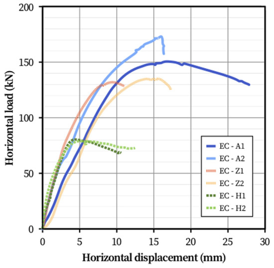
Figure 19.
Load-deformation diagram of all the specimens.
For the seismic performance evaluation of RE walls, the ductility serves as a critical indicator [23]. Table 3 summarizes the parameters used to determine the ductility factors of the tested walls. The ductility of the control group exhibits relatively good consistency, while the second and third groups show a certain degree of dispersion. The mean ductility value was highest in Group 1, followed by Group 3, and lowest in Group 2. Given that the experimental objective focuses on evaluating shear capacity, specimens with a low height/length ratio were intentionally designed. This configuration led to a reduction in wall ductility. Therefore, full-scale testing is imperative to accurately assess the ductility of RE walls with undulating joints.
Table 3.
Comparison of the ductility of the tested RE walls.
6. Integration of Seismic-Resistance Technology and Expressive Artistry for Undulating Jointed RE Walls
As the conservation of traditional villages and development of rural tourism continue to advance, RE walls have evolved beyond their conventional structural functions of load bearing or enclosure. Their landscape expressiveness has been significantly enhanced through diversified explorations of textural expression by artists and architects [31,32,33,34]. These practices exhibit dual outcomes. Some have enhanced structural performance (Figure 20), while others have unintentionally compromised structures. Excessive artistic interventions (e.g., deep surface carving or irregular perforations) disrupt material continuity, leading to the weakening of the shear capacity of RE walls.
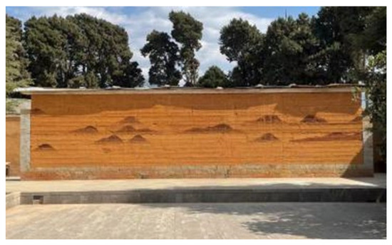
Figure 20.
RE wall in Shaxi town in Dali city.
6.1. Technical Contradictions in the Artistic Expression of RE Wall Textures
The term “technical contradiction” refers to the inconsistency between structural joint design and surface textural patterns. A typical example arises when architects prioritize horizontal textural continuity for esthetic cohesion, while structural engineers prefer advocating undulating joints to enhance walls’ shear capacity (Figure 21).
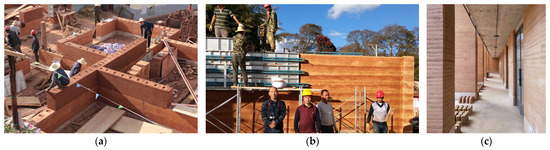
Figure 21.
Projects with load-bearing RE walls in a PGA 0.2 g level region, Yunnan province, China. (a) Construction site for a farmer’s house; (b) Construction site for a tourist village; (c) Yunnan Earth Architecture Technology Research Center.
6.2. Rationalization in Textural Expression and Technical Application of RE Walls
The term “rationalization” refers to a scenario in which the artistic textural expression and technical joint logic of RE walls exhibit superficial consistency. However, improper control of localized joint morphology may lead to structural failures. For instance, under horizontal seismic actions, semi-wave rammed wall sections on the far side of the force direction may disengage along the joints. Within this disengaged zone, both the shear capacity of the base material and interfacial friction become ineffective. Shorter RE wall segments are particularly prone to these types of extreme adverse conditions.
7. Conclusions
- Under consistent soil mixture ratios and ramming techniques, the undulating joint RE technology significantly enhances wall shear resistance solely through optimized joint morphology control. The maximum horizontal loads of the specimens with locally subsided joints are 132.44 kN and 135.41 kN, respectively, which is approximately 50% higher than that of the specimens with horizontal joints, whose maximum horizontal loads are 80.7 kN and 85.83 kN, respectively, while the maximum horizontal loads of the specimens with horizontally concatenated gentle arc-type joints are 151.17 kN and 173.58 kN, respectively, which exhibit nearly double the shear capacity.
- The maximum horizontal loads of specimens with locally subsided joints and horizontally concatenated gentle arc-type joints all exceed 87.02 kN, which satisfies the seismic resistance in a PGA 0.2 g level region. The outlined results were obtained based on a limited number of small-scale specimens tested in the current study. Further full-scale experiments on both static and dynamic behavior, complemented by numerical analysis, are required to more accurately evaluate the shear performance of RE walls with undulating joints.
- The innovation of undulating joint RE technology establishes a technical foundation for authentic textural expression in rammed walls. Architects should anchor esthetic manifestations in the structural–technical rationality of RE systems, and structural professionals must actively engage with the esthetic articulation of tectonic logic. This duality drives the convergent evolution of engineering practice, where artistic vision and technical rigor coalesce to redefine contemporary RE architecture.
- Although modern materials and structural technologies offer numerous solutions to enhance the shear capacity of RE buildings, premature technological obsolescence may result in resource-inefficient utilization while existing techniques remain underutilized. This paradigm demands upholding the ecological integrity, cultural authenticity, and modest materiality inherent to earthen architecture and pursuing simplicity, reliability, and cost-effectiveness in technological advancement. It is very important to maximize shear resistance gains through low-input refinement of traditional ramming processes in the low-carbon context.
Author Contributions
Conceptualization, J.X. and W.B.; methodology, W.B.; validation, R.X. and S.D.; formal analysis, J.X. and W.B.; investigation, J.X. and W.B.; resources, S.D.; data curation, W.B.; writing—original draft preparation, R.X.; visualization, R.X.; supervision, S.D.; project administration, W.B.; funding acquisition, W.B. All authors have read and agreed to the published version of the manuscript.
Funding
This research was funded by Chan Cheung Mun Chung Charitable Fund, grant number HZ2024F0029A. The APC was funded by Kunming University of Science and Technology.
Data Availability Statement
The original contributions presented in this study are included in the article. Further inquiries can be directed to the corresponding author.
Acknowledgments
The authors are deeply grateful to the Yunnan Provincial Engineering Seismic Research Center for its experimental facilities and personnel support. At the same time, the authors would like to extend sincere gratitude to Su Hexian and Zheng Zhong for their valuable suggestions. During the preparation of this manuscript, the authors used DeepSeek-V3(R1) to assist with the writing. The authors have reviewed and edited the output and take full responsibility for the content of this publication.
Conflicts of Interest
Author Wenfeng Bai was employed by the Chan Cheung Mun Chung Charitable Fund. The remaining authors declare that the research was conducted in the absence of any commercial or financial relationships that could be construed as a potential conflict of interest.
References
- Houben, H.; Guillard, H. Earth Construction: A Comprehensive Guide; Intermediate Technology Publications: London, UK, 1989. [Google Scholar]
- Institute for the History of Natural Sciences (CAS). A History of Chinese Ancient Architectural Techniques; China Architecture Publishing and Media Co., Ltd.: Beijing, China, 2016. (In Chinese) [Google Scholar]
- Knapp, R.G. China’s Old Dwellings; University of Hawai’i Press: Honolulu, HI, USA, 2000. [Google Scholar]
- Jiang, G.C. Yunnan Ethnic Vernacular Architecture; Yunnan University Press: Kunming, China, 1997. (In Chinese) [Google Scholar]
- Khadka, B. Rammed earth, as a sustainable and structurally safe green building: A housing solution in the era of global warming and climate change. Asian J. Civ. Eng. 2020, 21, 119–136. [Google Scholar] [CrossRef]
- Mu, J. Vernacular Earth Construction: Dialectics between Ancestral Techniques and Contemporary Praxis; Tongji University Press: Shanghai, China, 2023. (In Chinese) [Google Scholar]
- An, X.W.; Li, D. Typical earthquake damage analysis of Ludian earthquake with Ms 6.5. Build. Struct. 2020, 7, 28–36. (In Chinese) [Google Scholar]
- Reyes, J.; Yamin, L.; Hassan, B.W.; Sandoval, J.; Gonzalez, C.; Galvis, F. Shear behavior of adobe and RE walls of heritage structures. Eng. Struct. 2018, 174, 526–537. [Google Scholar] [CrossRef]
- Zhong, J.Q.; Wang, Y.H.; Liu, Q.J.; Yue, X.C. Experimental study on shear properties of modified raw-soil bulks. Build. Struct. 2016, 15, 106–109. (In Chinese) [Google Scholar]
- Cao, M.; Zhong, J.Q.; Zhang, Y.Y.; Wei, H.M.; Lv, S.Y. Research status of raw-soil material modification. Sichuan Build. Mater. 2011, 5, 1–4. (In Chinese) [Google Scholar]
- Bu, Y.H.; Wang, Y.H.; Li, L. Experimental study on seismic behavior of raw-soil structure with rammed earth walls by different construction methods. J. Chang. Univ. 2011, 31, 72–76. (In Chinese) [Google Scholar]
- Jiang, C.; Bai, Y.; Bai, W.F.; He, L. Experimental study on quasi-static test of the different reinforced rammed earth structures. Earthq. Resist. Eng. Retrofit. 2019, 4, 93–98. (In Chinese) [Google Scholar]
- Ge, X.L.; Zhu, L.X.; Huang, S.M. Implementation Guide to Aseismic Technical Specification for Building Construction in Town and Village; China Architecture Publishing and Media Co., Ltd.: Beijing, China, 2010. (In Chinese) [Google Scholar]
- Easton, D. The Rammed Earth House; Chelsea Green Publishing: Chelsea, VT, USA, 2007. [Google Scholar]
- Paul, G.M.; Gerald, W.M. Adobe and Rammed Earth Buildings; The University of Arizona Press: Tucson, AZ, USA, 1984. [Google Scholar]
- Sichuan Provincial Department of Housing and Urban Rural Development. Standard for Rural Rammed Earth Buildings Using Modern Technique; Southwest Jiaotong University Press: Chengdu, China, 2019. (In Chinese) [Google Scholar]
- Arslan, M.E.; Emiroğlu, M.; Yalama, A. Structure behavior of rammed earth walls under lateral cyclic loading: A comparative experimental study. Constr. Build. Mater 2017, 133, 433–442. [Google Scholar] [CrossRef]
- Liu, Q.; Tong, L.P.; Xu, Q.Q. Experiment on Seismic Performance of Rammed Earth Wall with Vertical Pin. J. Archit. Civ. Eng. 2018, 3, 79–86. (In Chinese) [Google Scholar]
- Shrestha, K.C.; Aoki, T.; Miyamoto, M.; Wangmo, P.; Pema. In-plane Shear Resistance between the Rammed Earth Blocks with Simple Interventions: Experimentation and Finite Element Study. Buildings 2020, 10, 57. [Google Scholar] [CrossRef]
- Zhang, J.X.; Tao, X.Y. Experiment study of shear behavior of rammed earth wall. Build. Struct. 2019, 10, 89–93. (In Chinese) [Google Scholar]
- NZS 4299; Earth Buildings Not Requiring Specific Design. Wellington: Princeton, NJ, USA, 1998.
- Xiang, W.; Nie, L.Z. Methodology of Soil Test State Control; Geology Press: Beijing, China, 2010. (In Chinese) [Google Scholar]
- Ramezanpour, M.; Eslami, A.; Ronagh, H. Seismic performance of stabilized/unstabilised rammed earth walls. Eng. Struct. 2021, 245, 112982. [Google Scholar] [CrossRef]
- Ruiz, D.M.; Reyes, J.C.; Alvarado, Y.A.; Vacca, H.; Tarque, N.; Jerez, S. Investigating Scale Effects on Experimental Shear Strength of Earthen Walls (Adobe and Rammed-Earth). Buildings 2025, 15, 689. [Google Scholar] [CrossRef]
- GB 50009-2012; Load Code for the Design of Building Structures. China Architecture Publishing and Media Co., Ltd.: Beijing, China, 2012. (In Chinese)
- GB 50011-2010; Code for Seismic Design of Buildings. China Architecture Publishing and Media Co., Ltd.: Beijing, China, 2010. (In Chinese)
- Uirich, R.; Christof, Z. Earth Building Practice Planning-Design-Building; Beuth: Berlin, Germany, 2011. [Google Scholar]
- Julian, K.; Roeland, K. Rammed Earth Structures A Code of Practice; Practical Action Publishing Ltd.: London, UK, 2011. [Google Scholar]
- El-Nabouch, R. Mechanical Behaviour of Rammed Earth Walls Under Pushover Tests. Ph.D. Thesis, Universite Grenoble Alpes—Universite Savoie Mont Blanc Annecy, Chambery, France, 2017. [Google Scholar]
- El Nabouch, R.; Bui, Q.-B.; Plé, O.; Perrotin, P. Rammed Earth Under Horizontal Loadings: Proposition of Limit States. Constr. Build. Mater. 2019, 220, 238–244. [Google Scholar] [CrossRef]
- Laetitia, F.; Romain, A. Bâti en Terre du Grain de Sable à l’Architecture; Tongji University Press: Shanghai, China, 2024. (In Chinese) [Google Scholar]
- Yang, F. An introduction to artistic expression of rammed earth wall. Art Educ. 2020, 11, 181–184. (In Chinese) [Google Scholar]
- Lu, Q.S. Modern Rammed Earth in Hospitality Design: Hotels and Guesthouses—Take Luogu Mountain Rustic Luxury Hotel as Example in Wuning County. Hous. Real Estate 2019, 24, 89–90. (In Chinese) [Google Scholar]
- Li, Y.; Wu, R.P.; Chen, S.Y. Research on the Design and Application of New Thin-wall Color Rammed Earth Decorative Wall. Archit. Cult. 2020, 7, 40–42. (In Chinese) [Google Scholar]


Disclaimer/Publisher’s Note: The statements, opinions and data contained in all publications are solely those of the individual author(s) and contributor(s) and not of MDPI and/or the editor(s). MDPI and/or the editor(s) disclaim responsibility for any injury to people or property resulting from any ideas, methods, instructions or products referred to in the content. |
© 2025 by the authors. Licensee MDPI, Basel, Switzerland. This article is an open access article distributed under the terms and conditions of the Creative Commons Attribution (CC BY) license (https://creativecommons.org/licenses/by/4.0/).