1. Introduction
Structural Concrete Insulated Panels (SCIPs) are increasingly favored within the construction industry due to the ongoing emphasis on enhancing the thermal efficiency of buildings [
1,
2,
3]. These panels are composed of two layers of concrete with an insulating material sandwiched between them. This insulating layer significantly boosts thermal efficiency, a crucial feature sought after in modern building designs aiming for improved energy conservation [
4]. Past research [
5,
6] has highlighted the significance of solutions that meet the increasing demand for energy-efficient, lightweight, and comfortable habitats, while also promoting rapid construction timelines. To tackle the global warming challenge, there is an increasing demand for sustainable construction approaches that combine energy efficiency, structural performance, and comfort [
7]. SCIPs, which have three or more layers, are well known for their exceptional structural effectiveness [
8]. These panels usually consist of thin, high-strength reinforced concrete outer layers, commonly known as wythes, covering a thicker, weaker insulating core [
8]. According to Bhatti et al. [
9], SCIPs can be made to any size, with widths ranging from 4 to 8 feet (1.2 to 2.4 m) and lengths up to 40 feet (12 m). Many industries, including aerospace [
10], naval [
11], and automotive [
12,
13], have expressed great appreciation for this exceptional construction. According to recent studies, this is because of their remarkable lightweight [
14] yet robust qualities [
15], delivering excellent bending stiffness and resistance to buckling [
15].
According to research by [
16], this precast technique yields high-quality concrete components. In the construction of SCIP, a vital component is the shear connector, a hardware element that links the two concrete layers and facilitates the transfer of forces between them [
17]. The diagonal arrangement of double shear connectors, which meticulously connects these layers, is essential to preserving the panel’s structural integrity and ensuring composite behavior [
18]. The composite activity of the panel is largely dependent on the performance of these shear connectors.
The design of SCIP can be categorized into non-composite, fully composite, or partially composite, which signifies the extent to which the two concrete layers collaborate in resisting loads [
18]. However, the extremes of composite behavior—non-composite and fully composite—imply unrealistic performance expectations for the connectors. Non-composite behavior suggests negligible force transfer or stiffness by the connector, whereas fully composite behavior assumes an infinitely rigid tie [
17].
As the popularity of partially composite panels grows and designers push the limits of their capabilities, there is an increasing effort to develop methods for their design and analysis [
18]. Many existing analysis [
19] and design methods [
20,
21,
22] have been validated by comparing their results to SCIP testing documented in the literature. One of the earliest attempts to characterize the behavior of SCIPs was made by Holmberg and Plem [
23], focusing exclusively on SCIPs made of concrete with steel truss connectors. Full-scale flexural tests were used in their study to assess the extent of shear transmission and composite action via the insulation.
Another significant contribution was made by Allen, H.G. [
24], who provided a comprehensive review of SCIP behavior for panels made of various configurations. Bai, F, JS Davidson [
19] subsequently verified methodologies within the elastic range, extended the approach proposed by Holmberg and Plem [
23], and concluded that they were suitable for elastic design of partially composite SCIPs. However, due to the intricate nature of SCIP behavior, the complexity of analysis methods, and challenges in integrating them into the design process, the industry currently relies on either simplified approaches or finite element analysis [
25]. In addition to traditional experimental methods such as three- or four-point bending tests and numerical approaches like finite element analysis (FEA) for evaluating load–deflection behavior, recent advancements in artificial intelligence have enabled the use of machine learning (ML) as a powerful predictive tool in structural engineering. ML models have shown strong potential in estimating mechanical performance, optimizing design, and reducing reliance on time-consuming physical testing. For example, ensemble machine learning approaches have been successfully applied to predict non-uniform shrinkage in steel–concrete composite slabs with high accuracy and interpretability, highlighting the value of explainable AI in structural analysis and design [
26,
27,
28,
29,
30]. Although ML is not applied in the current study, its integration into SCIP research represents a promising direction for future investigation.
Frankl et al. [
31] assessed how well precast prestressed concrete sandwich wall panels performed in terms of strength, lifespan, and thermal insulation when shear grids made of carbon fiber-reinforced polymer (CFRP) were used. Hamed [
32] examined precast concrete SCIPs reinforced with diagonal fiber-reinforced polymer (FRP) bars. The study found that the type, quantity, and spacing of shear connectors—which control the amount of composite action between wythes—have a significant impact on the load-carrying capacity of composite precast concrete SCIPs. The usefulness of continuous truss-shaped wire shear connectors in generating composite action was shown in a study on insulated concrete SCIPs incorporating wire mesh as shear connections [
33]. Continuous truss-shaped wire shear connectors greatly improve composite action, attaining up to 85% of the rigidity of a fully composite section, according to a study on insulated concrete SCIPs.
Lightweight SCIPs composed of expanded polystyrene (EPS) or mortar were the subject of study by Carbonari et al. [
34], which emphasized the significance of strong connections perpendicular to concrete layers to increase stiffness and decrease service limit state limitations. The deformability and fracture behavior of precast lightweight foam concrete SCIPs (PLFP) combined with double shear steel connectors were investigated under typical service loads; the results showed that the effect on structural stiffness was minimal [
8]. Analysis has been performed on the structural behavior of SCIPs made of foam-insulated concrete under continuous pressure. The findings underscored the need for numerical evaluations to incorporate simulated shear tie resistance for improved design and analysis, particularly for blast and static loadings [
35]. Fam and Tomlinson [
36] showed the effectiveness of their analytical model in the bending behavior of SCIP.
Ahmad and Singh [
37] brought attention to the impact of edge conditions on failure mechanisms and load capacity in their investigation of reinforced concrete SCIPs (RCSP) with an Expanded Polystyrene (EPS) core. Finally, a study by Leubke and colleagues highlighted the significance of material and connection choices on thermal and structural performance during the design process with regard to SCIPs, especially those with thicker insulation [
18]. With a measured ratio of 0.82, the shear flow technique, however, overestimated the shear capacity of thick insulation panels. Shear connectors aid in force transfer and maintain panel strength even if the concrete–foam contact deteriorates over time [
38].
Prior research, discussed earlier, on Structural Concrete Insulated Panels (SCIPs) has mostly concentrated on fixed-ended settings, which has limited the understanding of how the panels behave in situations involving more flexible support. By assessing SCIP behavior under pinned-ended situations, this study adds to the body of literature by offering a more thorough comprehension of their flexural performance, deflection properties, and composite action in practical structural applications. This research also examined the behavior of panels using different thicknesses of top and bottom wythes with the additional reinforcement in these wythes at different spacing values other than the one used in the literature [
19,
20,
21,
22,
23,
24,
25,
36,
38,
39,
40,
41,
42]. In this study, several SCIPs are tested with and without additional steel (#3@4.5 inches and #3@8 inches in the top wythe and #3@8 inches in the bottom wythe). The top wythe of SCIP panels is reinforced to improve flexural strength, prevent cracking due to heat loads and shrinkage, and guarantee structural integrity. Additionally, it encourages composite action between the insulation and wythes, which enhances panel performance as a whole.
This disparity highlights the need for a thorough investigation that can result in improved design principles and building techniques. Moreover, there is still a need to investigate deflections of SCIP using the criteria of the ACI 318 code [
43] as per Mohamad et al. [
8]. This study provides empirical data on the performance of SCIPs with various reinforcement configurations under pin-ended conditions, offering insights into their load-bearing capacities and compliance with ACI 318 [
43] deflection criteria, which were previously underexplored in the context of floor slab applications.
The paper is organized to give information on the testing approach in
Section 2, followed by an explanation of calculating the degree of composite behavior in SCIPs in
Section 3.
Section 4 discusses observed damages and failure mechanisms in experiments. Subsequently,
Section 5 summarizes results and presents a discussion, which is followed by conclusions and further work recommendations.
2. Materials and Methods
2.1. Material Used
In this research, fire-resistant Expanded Polystyrene (EPS) panels were utilized to produce prototypes of Structural Concrete Insulated Panels (SCIP). These EPS panels were produced at a factory (Norwest Group Pvt. Ltd., Hattar, Pakistan) and were always 100 mm thick with a density of 15 kg/m3. They were designed with corrugations on both sides to guarantee consistent thickness. Expanded Polystyrene (EPS) panels with corrugations help ensure equal thickness by offering structural stiffness and consistency throughout the production process. Corrugations’ ridges and grooves lessen the possibility of material deformation or uneven compression, guaranteeing that the panel’s thickness stays consistent throughout. Additionally, by strengthening the panel and increasing its resistance to outside forces, these corrugations reduce the likelihood of warping, particularly during handling, transit, and installation. They also produce air pockets inside the panel, which improves its thermal insulation qualities even further while keeping its thickness constant. The dimensions of the tested SCIPs were 175.5 mm in thickness, 609.6 mm in width, and 3048 mm in length. They had a 50 × 50 mm wire mesh grid with a diameter of 2.5 mm. The wire meshes were joined by 45-degree angled diagonal shear connections that were placed 100 mm apart. These connections were welded to the mesh using wires thicker than 2.65 mm.
The panels’ top wythe was made of self-compacting concrete, and the bottom wythe was shotcreted, which complied with ACI 318 guidelines [
44]. The top and bottom concrete wythes measured 63.5 mm and 12 mm in thickness, respectively. Tensile tests were performed on the steel bar truss component and the mesh in accordance with ASTM E8 standard [
45]. In addition, the concrete’s compressive strength was evaluated in three samples as shown in
Table 1, and after 28 days, it reached 18.13 MPa. Every concrete sample was tested (
Figure 1) in accordance with ASTM (Anon 2005) [
46] procedures, guaranteeing a thorough and consistent assessment, using 150 mm cube specimens. Although ASTM C39 [
46] is primarily intended for cylindrical specimens, a similar testing procedure was followed, with necessary adjustments to loading rate and platen contact to accommodate cube geometry, thereby ensuring consistency and reliability in results.
Table 2 lists the properties of the materials that were utilized to make SCIPs except for concrete, which is shown in
Table 1.
2.2. Details of Specimens
The four panels under investigation in this experimental study are characterized by changes in reinforcement. The panels are classified based on whether extra reinforcement is included, with special emphasis paid to the spacing and location of the reinforcement.
SCIP-1 represents a panel with no additional reinforcing (
Figure 2a).
SCIP-2 indicates a panel with reinforcement #3 at 200 mm spacing in the bottom wythe (
Figure 2b)
SCIP-3 denotes a panel with reinforcement #3 at 112 mm spacing in the bottom wythe (
Figure 2c)
SCIP-4 denotes a panel with reinforcement #3 at 200 mm spacing in the top wythe (
Figure 2d).
The details are organized in tabular form in the
Table 3 to provide a full overview of the specimens.
2.3. Casting of Panels
Wire mesh was first positioned in the formwork. To completely cover the wire mesh and shear connectors, the initial layer of concrete was manually applied and spread across the EPS surface. Concrete was applied in layers, beginning with small areas and then spreading uniformly, as can be seen in
Figure 3. Before adding more concrete layers, cement slurry was used to improve bonding between layers. To create a level surface and keep a constant thickness throughout the panel, the concrete was manually spread. The surface was rigorously finished with trowels to produce a smooth and even finish after the top layer was applied and leveled.
To guarantee adequate hydration and strength development, the panels were allowed to cure after setting. In order to prevent premature drying and guarantee sufficient strength gain, the panels were covered and often misted with water during the 28-day curing process. The panels were taken out of the formwork once they had completely dried and were prepared for installation and structural testing.
This process produced SCIPs in a regulated, consistent, and high-quality manner, which made them appropriate for walls, floor slabs, and structural applications needing strength and thermal insulation.
2.4. Testing Arrangement
Four-point bending tests were performed as part of the testing process in accordance with ASTM E72 standards [
47]. As shown in
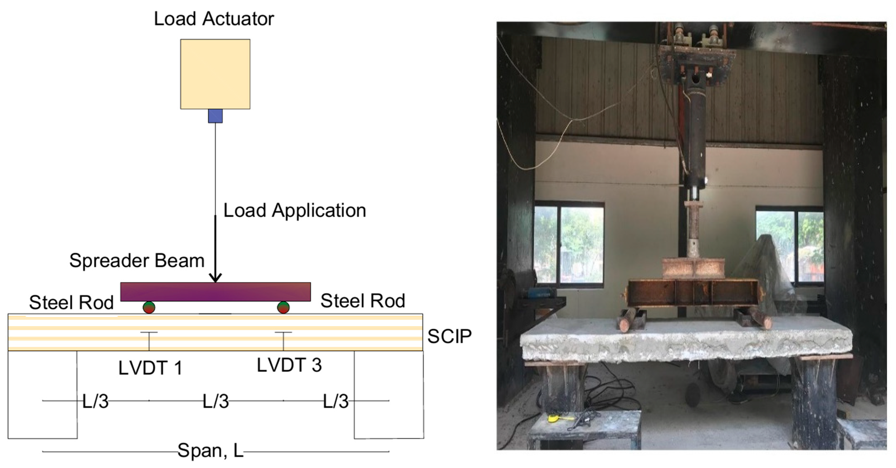
Figure 4, these tests entailed applying a transverse out-of-plane force on slab panels. A load actuator, a spreader beam, steel rods for support, and linear variable displacement transducers (LVDTs) for measuring deflection made up the testing apparatus. Through a spreader beam, which uniformly distributed the supplied force, the load actuator applied a vertical load at the SCIP’s midspan. To ensure a pinned-ended condition and allow for unfettered rotation, the specimen was only held by two steel rods.
To measure deflections at various locations throughout the span, two LVDTs (LVDT 1 and LVDT 3) were placed L/3 apart from each support, where L is the center-to-center span equal to 2548 mm. These LVDTs captured the panel’s deflection in real time as the load increased. The ASTM E72 [
47] monotonic loading was used for testing, ensuring progressive testing with minimum inertial dynamic impacts. A load-controlled servo-hydraulic actuator was used to apply transverse out-of-plane loading to the specimen. Load increments of 0.5 kN/sec were applied to the specimen up to a maximum level before failure. The maximum load was held constant at each load increment for a predetermined time to identify cracks and track their pattern and progression. The specimens were then gradually subjected to the following load increment.
It is noted that the steel plates used to apply the four-point bending load did not extend through the full thickness of the SCIPs. This setup was intentionally adopted to simulate localized contact loading conditions typically encountered in real-world applications such as floor slabs, where loads are often applied over partial surface areas rather than uniformly across the panel thickness. Despite the reduced contact depth, the plates were sufficiently rigid to distribute the applied load effectively without inducing localized crushing or stress concentrations. No evidence of localized failure was observed under the plates during testing. Additionally, the panels exhibited clear flexural behavior, as reflected in the development of distributed flexural cracks and the expected moment–deflection trends, confirming that the load was transferred effectively into the panel cross-section. Therefore, although the setup deviates from idealized full-thickness loading, it accurately represents the structural behavior of SCIPs under realistic service conditions.
Two linear variable displacement transducers with a 100 mm (4 inch) range were used to measure the deflection of the panels under the applied loads. Loads and deflections were captured at a rate of 50 Hz by the data-collecting system, providing a thorough insight into the specimen’s behavior during the four-point bending tests.
3. Composite Action
SCIPs fall into one of three kinds according to the degree of composite activity achieved. This section explains the process of estimating composite action in SCIP.
3.1. Non-Composite Ultimate Moment
The ultimate moment of a non-composite SCIP (
), which represents its maximum bending capacity, can be determined by adding together the ultimate moments of each of its individual layers, or wythes. These formulas are grounded in the principle of strain compatibility, which ensures that each component of the panel deforms uniformly under stress. It is important to note that there might be slight variations in these calculations, as indicated by Olsen and colleagues in their 2017 study [
21]. This approach provides a comprehensive and accurate method for assessing the structural capacity of such panels:
As1, As2 = Area of steel in top and bottom wythe, respectively.
d1, d2 = Depth of top steel from outer layer and depth of bottom steel from bottom of insulation layer, respectively.
fs1, fs2 = Tensile stress in the top and bottom wythe steel, respectively.
a1, a2 = Depth of equivalent stress block for the steel in the top and bottom concrete wythes, respectively.
3.2. Fully Composite Ultimate Moment
The process for calculating the fully composite moment (
in SCIP, according to Equation (5), assumes that the entire panel functions as a single, cohesive beam without any breaks or irregularities in strain. To achieve this, a technique based on strain compatibility is to be used [
21]. This method is particularly applicable to panels reinforced with mild steel, though it can be slightly adjusted to suit panels that are prestressed. The goal of this approach is to ensure that all parts of the panel work together seamlessly, maintaining a uniform strain and effectively distributing the stress across the panel.
As1, As2 = Area of steel in top and bottom wythe, respectively.
d1, d2 = Depth of top steel from outer layer and depth of bottom steel from bottom of insulation layer, respectively.
fs1, fs2 = Tensile stress in the top and bottom wythe steel, respectively.
a1, a2 = Depth of equivalent stress block for the steel in the top and bottom concrete wythes, respectively.
twy1 = Thickness of top wythe.
tins = Thickness of insulation layer.
3.3. Degree of Composite Action
The degree of composite action, K
Mn, in the tested SCIP can be determined using Equation (6). It combines three essential elements that can be used to determine the degree of composite action in SCIP: the real moment, which is acquired from either experimental data (
) or a prediction model, the theoretical fully composite moment, and the theoretical non-composite moment [
21].
Mn,test represents the SCIP’s experimental maximum moment.
Mn,NC represents the non-composite SCIP’s theoretical maximum moment.
Mn,FC represents the fully composite SCIP’s theoretical maximum moment.
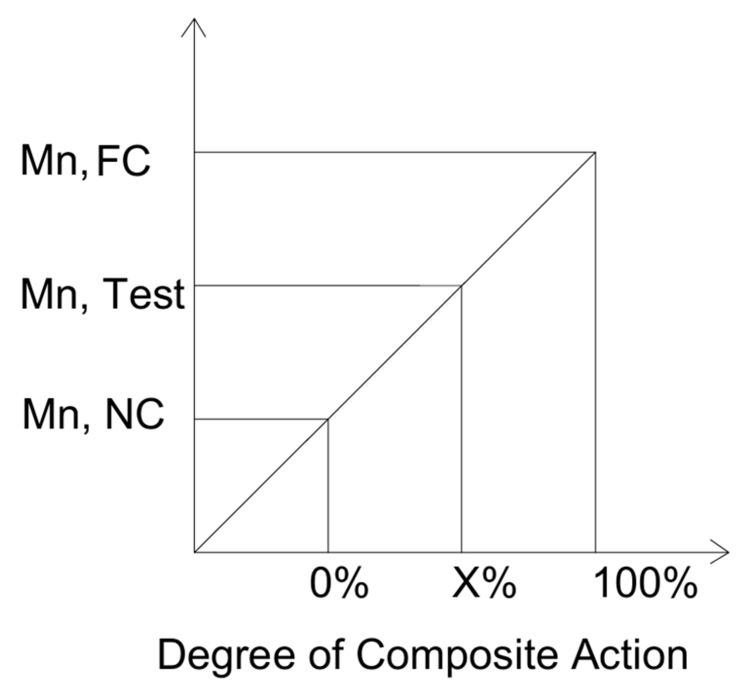
By analyzing the panels’ moment capacity under various circumstances,
Figure 5 shows the extent of composite activity in structural concrete insulated panels (SCIPs). The diagram highlights the gradual increase in moment capacity as the degree of composite action increases from 0% to 100% [
21].
4. Observed Damages and Failure Mechanism
Each specimen was subjected to a four-point bending test covering the numerous panel configurations described in the paper. Structural concrete insulated panels comprising extra reinforcement and steel bars at varied spacings were placed under pin-pin ended conditions, as shown in
Figure 4.
Progression of damage in SCIP as the moment increase is shown in
Figure 6. Hairline cracks appeared on the bottom wythe of each sample after loading, notably in the critical moment zone between point loads. The load–deflection graph showed a modest curve deviation at first, corresponding to these early cracks, with their width and length gradually expanding as the applied weight increased. Concurrently, more cracks formed in the critical moment area, eventually merging into a dominant crack. The primary crack across the entire width of the panel eventually designated the failure plane. The behavior of the bottom wythe under flexural loading reflected a ductile response, characterized by gradual crack propagation and distributed deformation. Flexural action was recognized as the regulating factor in the ductility, defining the failure mode of all specimens. Notably, significant inelastic deformation occurred prior to failure, especially within the critical moment zone and reaching nearly to the center of the panel.
Discrete auditory signals were observed throughout testing, manifesting as little and big popping sounds, related to the breaking of mesh and shear connectors.
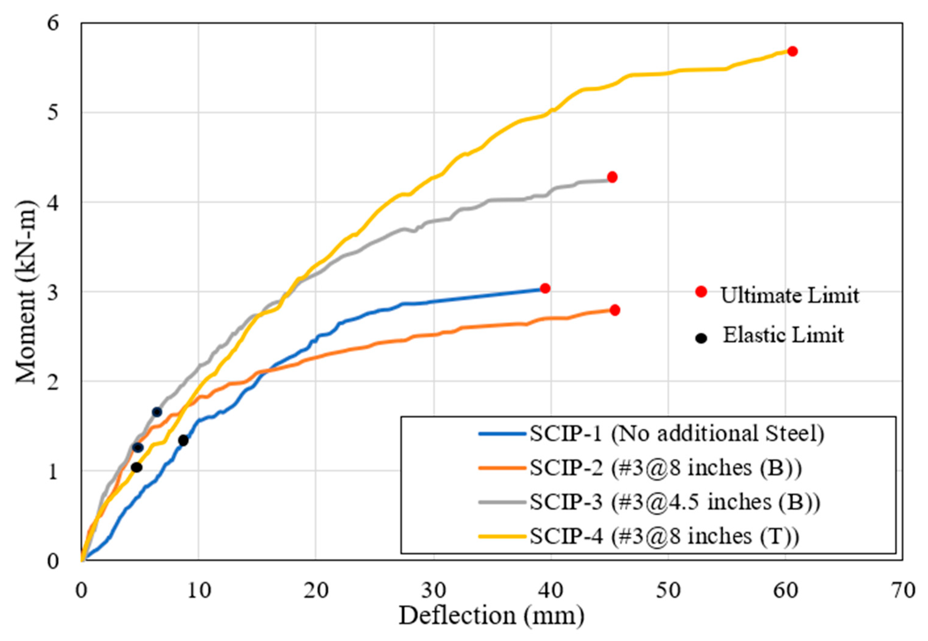
Figure 7 compares the moment deflection curves of all 4 tests with elastic and max points marked on the curves. The following subsection discusses the observed damage mechanism in each test.
4.1. Panel with No Additional Steel (SCIP-1)
The initial portion of the curve exhibits a linear pattern, representing the elastic phase of the panel’s behavior, where small deflections occur under gradually increasing load. As the load increased, a deviation from this linearity was observed, indicating the onset of cracking or yielding within the panel. This transition point is critical, as it marks the initiation of micro-cracks, which were visually confirmed in subsequent examinations. The formation of these cracks resulted in a rapid increase in deflection, signaling a shift to plastic behavior. Despite the emergence of these cracks, the panel continued to bear additional loads, reflecting its ductile nature.
As the load increased, a deviation from this linearity was observed, indicating the onset of cracking or yielding within the panel. This transition point is critical, as it marks the initiation of micro-cracks, which were visually confirmed in subsequent examinations. The formation of these cracks resulted in a rapid increase in deflection, signaling a shift to plastic behavior. Despite the emergence of these cracks, the panel continued to bear additional loads, reflecting its ductile nature. The load–deflection curve showed a plateauing effect after the initial cracking, with deflections continuing to increase even as the load increased, albeit at a slower rate. This suggests that the panel experienced a significant structural change, like the coalescence of micro-cracks into more extensive cracks, as visible in the post-test images. Notably, the panel did not experience a catastrophic failure; instead, it demonstrated a progressive failure mode, characteristic of ductile systems.
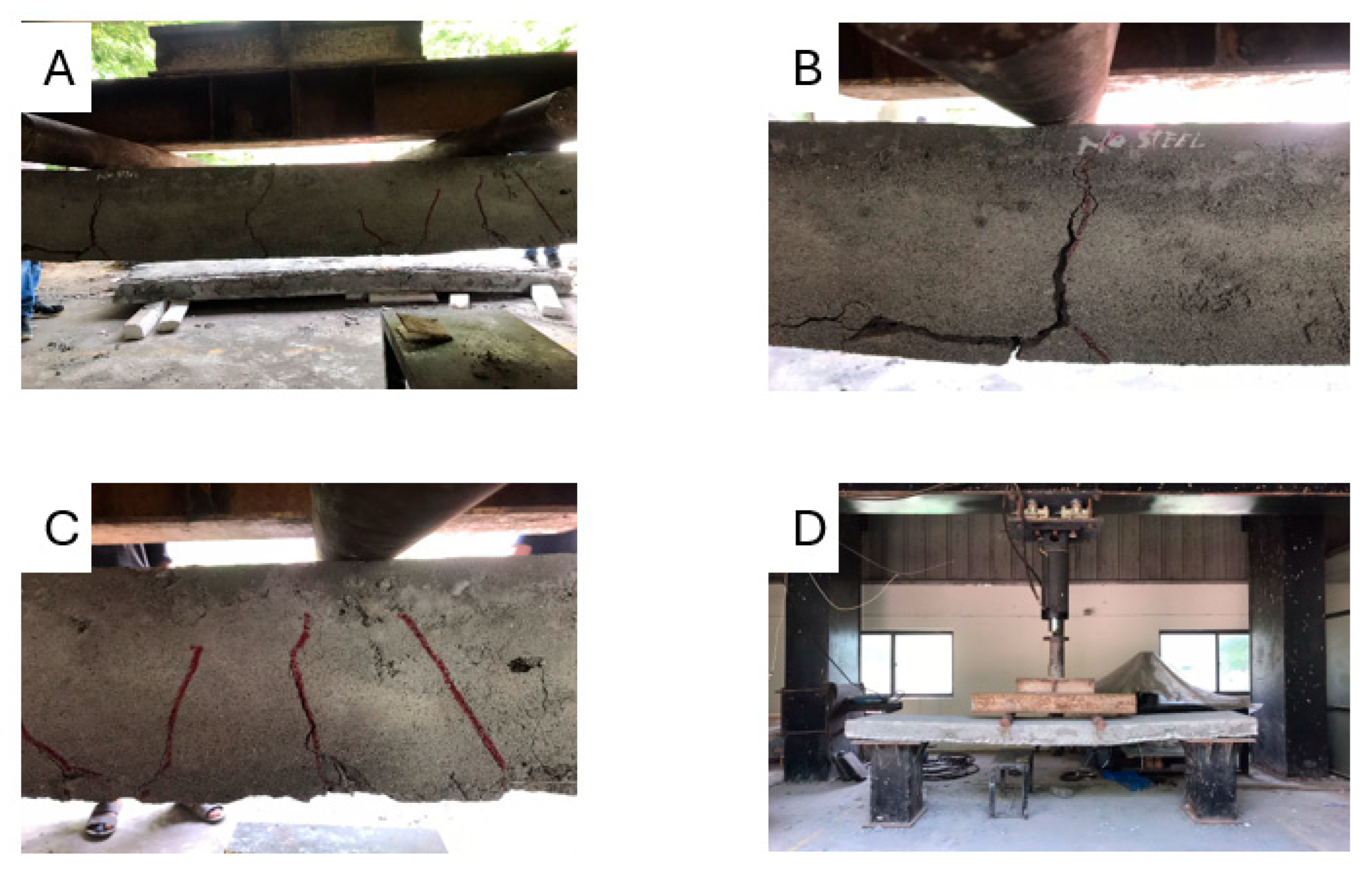
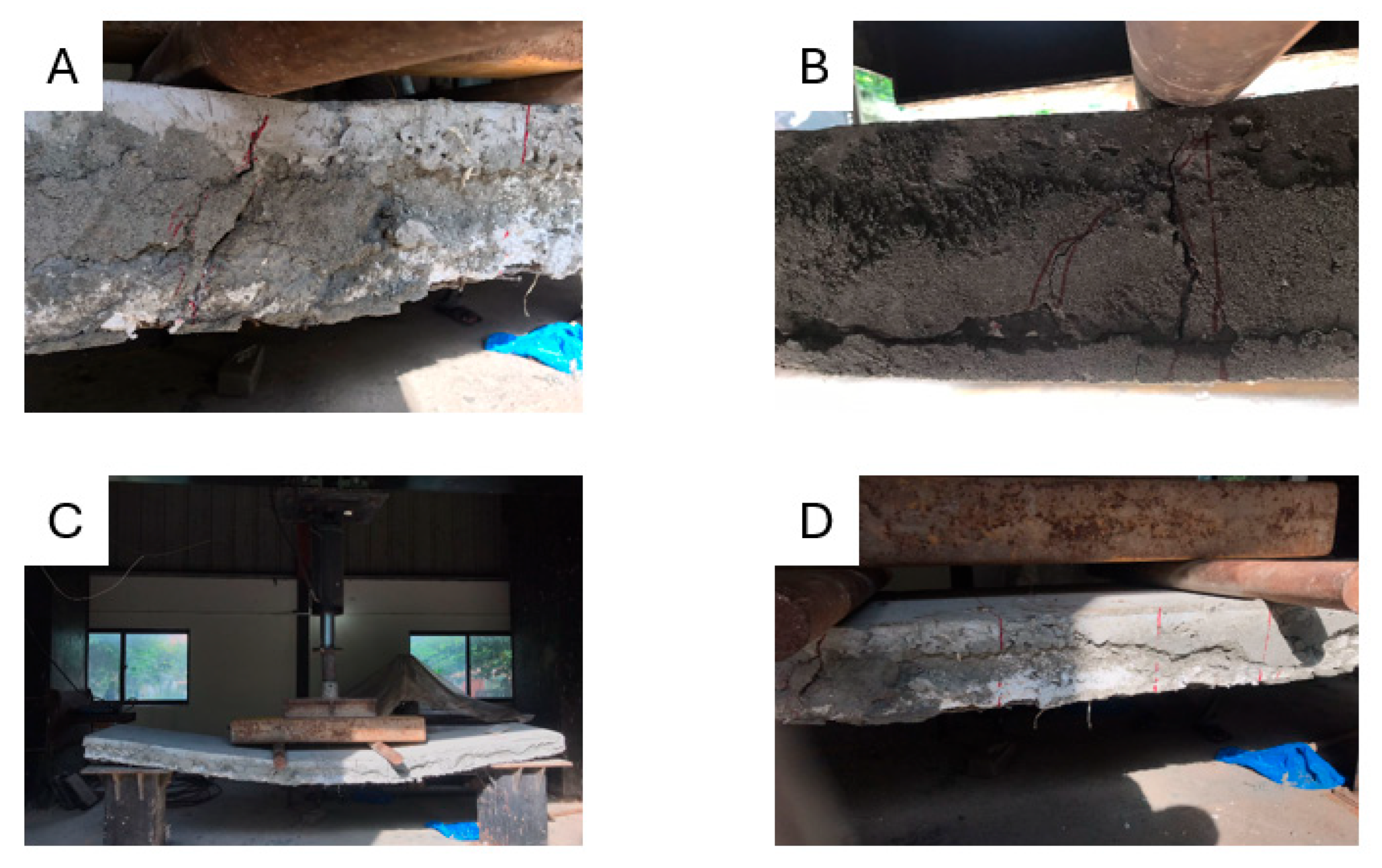
Photographs taken during and after the test
Figure 8A–D highlight the formation of flexural cracks, which predominantly appeared in the bottom regions of the panel, near the tension face, and propagated upwards toward the neutral axis. These flexural cracks are parallel to the bending moment, indicative of flexural stress as the dominant failure mechanism. The cracks appeared to be more pronounced near the areas of maximum moment, between the point loads.
The wire mesh reinforcement within the panel played a crucial role in controlling the extent and width of the cracks, preventing a sudden brittle failure and allowing the panel to maintain structural integrity even after significant cracking. However, some diagonal cracks observed near the ends of the panel suggest the possibility of minor shear forces influencing the overall failure pattern.
Throughout the testing process, the panel demonstrated considerable load-bearing capacity, even after the initial failure. This ductility implies a certain degree of redundancy in the structural system, allowing the panel to continue resisting loads and deform plastically, rather than experiencing a collapse.
The flexural failure mode observed in SCIP-1 aligns with expectations for such panels, where the bending moment governs the failure behavior. The presence of a continuous wire mesh ensured that the panel maintained its composite action, enhancing its toughness and ability to absorb energy under load. This behavior demonstrates the suitability of SCIP panels for use in floor slab applications, where flexural stresses are predominant.
4.2. Panel with #3@8 Inches in Bottom Wythe (SCIP-2)
The performance of SCIP-2, which had additional #3 reinforcing bars spaced 200 mm apart in the bottom wythe, when compared to the non-reinforced SCIP-1, showed a notable improvement in structural behavior. The curve exhibits a linear, elastic response during the initial loading period, demonstrating the panel’s capacity to sustain higher loads with minor deflection. As the load increased, the curve transitioned into a non-linear phase, signaling the onset of micro-cracking and plastic deformation within the panel. The inclusion of reinforcement in SCIP-2 delayed the initiation of significant cracking, as evidenced by the higher load-bearing capacity at the onset of non-linear behavior compared to SCIP-1. This delay in cracking demonstrates the positive effect of reinforcement in enhancing the panel’s overall stiffness and resistance to early structural damage.
A gradual decrease in the slope of the curve, as seen in the later stages of the test, indicates substantial structural changes such as the yielding of reinforcement and further propagation of cracks. The plateauing of the curve suggests that the reinforcement bars continued to resist additional load even after significant concrete cracking had occurred. This behavior reflects the ductility imparted by the reinforcement, allowing for gradual progression to failure rather than a sudden, brittle collapse.
The photographs, as shown in
Figure 9A–D, taken during and after the test, reveal fewer but broader cracks compared to the non-reinforced panel. The reinforcement bars altered the crack pattern, resulting in more distributed cracking across the panel’s surface, rather than concentrated crack formations in specific zones. The cracks, primarily flexural in nature, initiated at the bottom of the wythe and propagated upwards, like SCIP-1. However, the reinforced nature of SCIP-2 led to delayed crack propagation, and some evidence of diagonal cracking suggests the potential influence of shear forces, although flexural failure remained the dominant mode.
The presence of reinforcement significantly improved the panel’s load-bearing capacity, as the SCIP-2 panel was able to carry a higher load before significant cracking occurred. The mixed failure mode observed in SCIP-2, characterized by both flexural and potential shear components, demonstrates the interaction between concrete and reinforcement. The ability of the panel to resist higher loads after the first failure highlights the composite action between the wythes and the reinforcement bars.
In terms of ductility, SCIP-2 exhibited a more gradual failure process compared to the brittle-like failure of SCIP-1. This enhanced ductility, provided by the reinforcement, indicates a resilient design capable of withstanding higher loads and deformations before ultimate failure. The moment–deflection
Figure 7 data further support this, with SCIP-2 achieving a higher overall load-bearing capacity and a more controlled, predictable failure pattern.
4.3. Panel with #3@4.5 Inches in Bottom Wythe (SCIP-3)
The flexural behavior of SCIP-3, which includes #3 reinforcement bars spaced at 112 mm in the bottom wythe, was evaluated through a four-point bending test. The moment–deflection curve of SCIP-3 (
Figure 7) highlights the structural response of the panel under increasing loads. The initial linear portion of the curve indicates elastic behavior, reflecting the stiffness of the panel. The higher slope of the curve in this region suggests a stiffer response compared to SCIP-2, which can be attributed to the closer reinforcement spacing in the bottom wythe.
As the load increased, a slight divergence from the linear behavior marked the onset of cracking or yielding. This shift signals the initiation of micro-cracking within the panel, a key indicator of transition from elastic to plastic behavior. The plateau in the load–deflection curve suggests that while cracking continued to propagate, the panel’s reinforcement allowed it to maintain its load-bearing capacity, delaying catastrophic failure.
Photographic evidence, as shown in
Figure 10A–C, provides insights into the crack pattern and failure mechanism of SCIP-3. The flexural cracks, which initiated at the bottom wythe (tension zone), propagated upwards towards the compression zone, confirming a primarily flexural failure mode. However, compared to SCIP-2, the closer reinforcement spacing in SCIP-3 resulted in tighter crack patterns, reducing the extent of crack propagation and controlling crack width. This is particularly noticeable in the high-stress zones between the point loads, where the reinforcing steel significantly delayed the progression of cracks.
The moment–deflection curve also shows that SCIP-3 achieved a higher ultimate load capacity than SCIP-2, reaching approximately 12 kN before significant structural changes occurred. The continued rise in load with increasing deflection, even after cracking, demonstrates the ductile behavior imparted by the closely spaced reinforcement. The bars’ yielding further contributed to the panel’s ability to sustain higher loads after initial cracking, resulting in a more controlled failure progression.
The observed failure mode for SCIP-3 can be classified as a combination of concrete cracking and reinforcement bar yielding, with a focus on flexural failure. The closer reinforcement spacing in SCIP-3 compared to SCIP-2 contributed to better crack management, limiting the spread of cracks and improving overall panel ductility. This behavior indicates the effectiveness of tighter reinforcement spacing in enhancing both the stiffness and ductility of structural concrete insulated panels, particularly in floor slab applications.
In terms of overall performance, SCIP-3 demonstrated significant improvements in load-bearing capacity, stiffness, and crack control when compared to panels with wider reinforcement spacing. The load–deflection curve provides a comprehensive basis for comparing the structural behavior of SCIP-3 with other panel types, highlighting the influence of reinforcement placement and spacing on flexural performance.
The findings from the SCIP-3 test underscore the importance of optimal reinforcement placement in enhancing both the stiffness and toughness of SCIP panels. The closely spaced reinforcement in SCIP-3 resulted in a higher load-bearing capacity and a more controlled, gradual failure mode, confirming the panel’s suitability for applications requiring high flexural strength and ductility.
4.4. Panel with #3@8 Inches in Top Wythe (SCIP-4)
The flexural behavior of SCIP-4, which features #3 reinforcement bars at 200 mm spacing in the top wythe, was investigated through a four-point bending test. The moment–deflection curve for SCIP-4 (
Figure 7) reveals a distinct structural response compared to previous configurations with bottom wythe reinforcement. The initial portion of the curve shows a linear relationship between load and deflection, representing the elastic response of the panel and its stiffness under loading conditions.
As the load increased, a noticeable shift in the slope of the curve indicated the onset of cracking or yielding within the panel. This shift marks the transition from elastic to plastic behavior, signaling the beginning of structural damage. The ultimate load capacity of SCIP-4, as shown by the peak of the curve, was higher than that of the previous panel configurations, reaching approximately 18 kN. The top wythe reinforcement appears to have contributed to this increase in load capacity by strengthening the upper section of the panel, where tensile stresses may develop due to flexural bending.
The post-peak behavior of the curve indicates a gradual decline in stiffness, signifying the progressive propagation of cracks and potential yielding of the top reinforcement bars. Despite the onset of cracking, the panel exhibited ductile behavior, allowing for further load-bearing capacity after the initiation of damage.
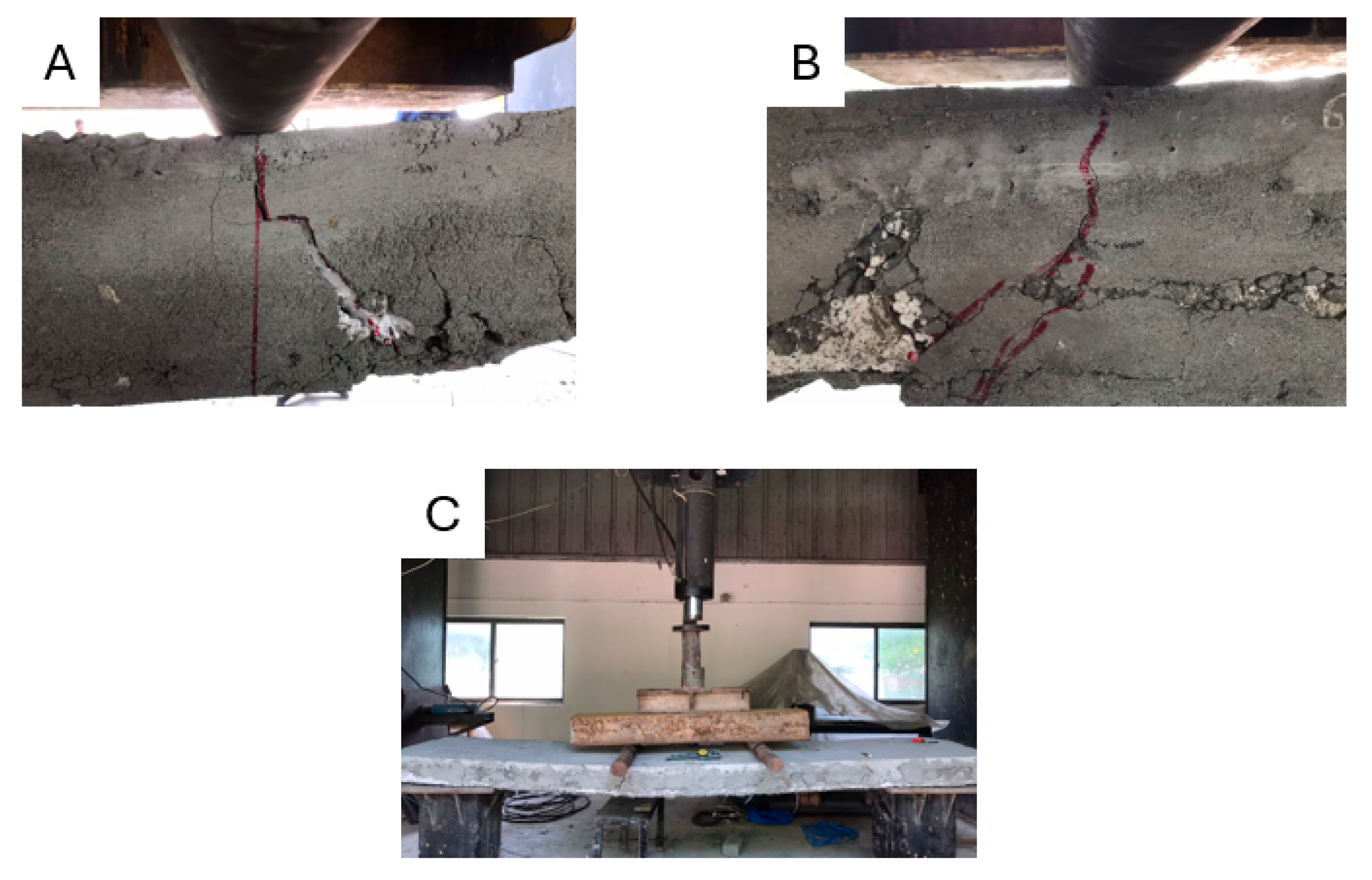
Photographs taken during and after the test, as provided in
Figure 11A–C, reveal the crack patterns and failure mechanism in SCIP-4. The presence of flexural cracks, predominantly in the bottom region of the panel, suggests that flexural stresses dominated the failure mode. However, the top reinforcement played a significant role in delaying crack propagation and controlling crack width. This reinforcement configuration resulted in a more gradual progression of cracking compared to panels with reinforcement only in the bottom wythe.
The moment–deflection data suggests that SCIP-4 demonstrated a higher overall ductility than the previous panels, with top wythe reinforcement aiding in controlling the progression of cracks and allowing the panel to withstand higher loads. The gradual post-peak decline in load indicates that the reinforcement bars continued to carry load even as the panel underwent substantial deformations.
The failure mechanism of SCIP-4 can be classified as primarily flexural, with cracks initiating in the tension zone (bottom wythe) and propagating upwards. The presence of top wythe reinforcement likely mitigated the severity of crack propagation, resulting in a more controlled and ductile failure process. This behavior underscores the importance of reinforcement placement in influencing the failure mode, crack patterns, and load-bearing capacity of structural panels.
Overall, SCIP-4 exhibited enhanced performance in terms of load-bearing capacity, ductility, and crack control compared to other configurations with bottom wythe reinforcement. The inclusion of top reinforcement contributed to a distinct failure pattern, characterized by a more gradual failure process and improved crack management. This configuration is particularly advantageous for applications where flexural strength and crack control are critical, such as floor slabs subjected to significant bending moments.
These findings highlight the impact of reinforcement placement on the structural behavior of SCIP panels, providing valuable insights for optimizing reinforcement configurations to enhance both stiffness and ductility. The load–deflection data for SCIP-4 serves as a basis for comparing the performance of different panel configurations, contributing to a broader understanding of the composite action in structural concrete insulated panels.
5. Results and Discussion
Hairline cracks started to appear on the bottom wythe of all specimens between load values of 4 and 8 kN, mostly in the critical moment zone, which is the area between the point loads. The moment–deflection curve shows this early cracking as a little divergence. These cracks grew longer and wider as the load rose, and more cracks appeared in the critical area until a dominant crack appeared. As the load was progressively raised outside of this area, fewer cracks emerged. The prominent crack, which marked the failure plane, ran the length of the panel between 8 and 18 kN. Multiple flexural cracks showed that the specimens had good ductility and could re-distribute stresses, with significant inelastic deformation taking place before failure.
A graphical technique called the initial tangent line method has been used to calculate the elastic deflection of structural parts from a non-linear load–deflection curve. Many times, cracking, yielding, or connection slides cause the relationship between applied load and deflection to become non-linear beyond the elastic limit. A tangent at the curve’s origin, which represents the structure’s initial stiffness, was drawn to isolate the elastic behavior. Corresponding deflection was determined by projecting the service load onto this tangent, making sure that the outcome only showed elastic deformation, which is necessary for serviceability inspections in accordance with design requirements.
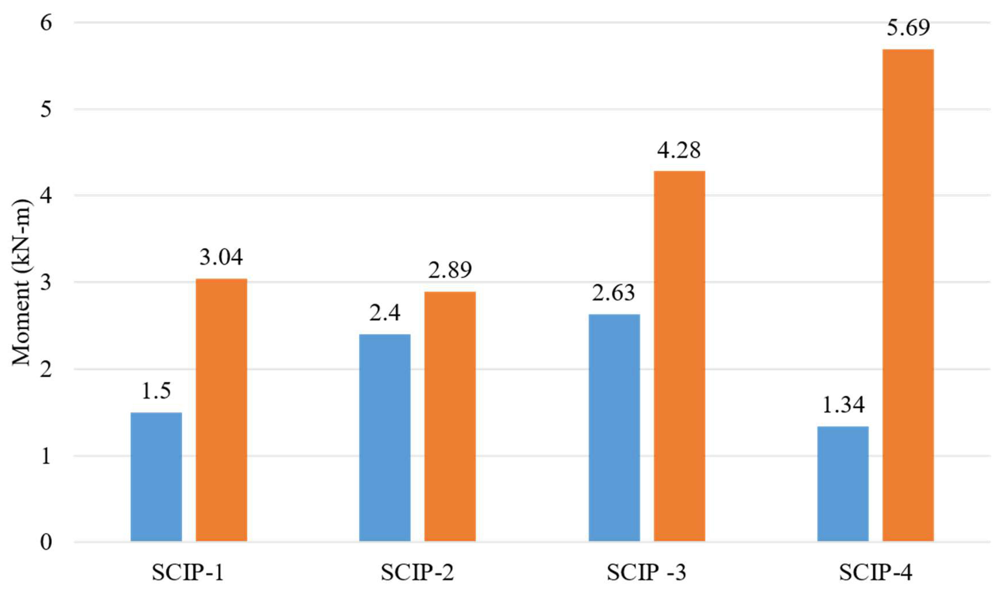
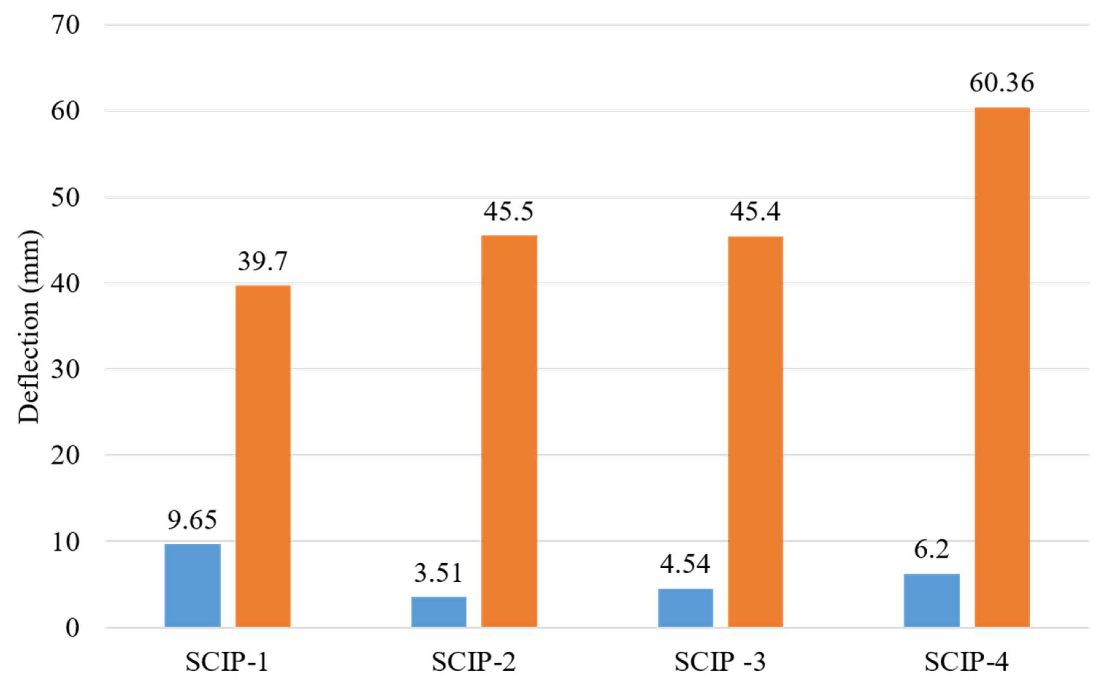
Table 4 shows the capacities of panels in the form of elastic and maximum moments with corresponding deflections in the tabular form.
Figure 12 and
Figure 13 are the graphical representation of the tested panels capacities and their deflections. These figures are depicting the comparison of tested panels.
5.1. Degree of Composite Action of Tested Panels (SCIPs)
Theoretical calculations were performed to evaluate the influence of reinforcing bars (rebars) on the composite behavior of Structural Concrete Insulated Panels (SCIPs) as a substitute for a conventional concrete slab. These calculations were carried out at the ultimate strength of the panels to estimate the extent of composite action. Estimating the ultimate flexural strength of SCIPs using traditional methods presents challenges due to uncertainties surrounding the level of composite action between the two wythes and its effect on the transverse load-carrying capacity. Nevertheless, an analysis of the extremes—ranging from fully composite to non-composite action—was undertaken. The approach used to determine the degree of composite action at the ultimate strength stage followed a series of defined steps.
Figure 14 shows the stress and load profile for both composite and non-composite sandwich panels. These profiles are of great help while determining the composite action of panels.
Table 5 is comprising of the moment values obtained through experiment and calculated moment values for composite and non-composite actions. Based on these moments, the degree of composite action for each panel has been tabulated.
These results from the experiment showed that the four SCIPs had different composite actions, each due to the presence and configuration of reinforcement. In this regard, SCIP-1, without additional steel reinforcement, exhibited a small composite action amounting to 28.2%, which developed an ultimate moment of 3.04 kN-m. This would suggest that some composite behavior can be achieved with the intrinsic design and material properties of the panel, even without reinforcement. In contrast, SCIP-2 was reinforced in the bottom wythe and represented the lowest degree of composite action at 6.5% with an ultimate moment of 2.84 kN-m. This suggests that locating reinforcement 200 mm within the bottom wythe may not be an effective placement to enhance composite action. As expected, the closer reinforcement in the bottom wythe of SCIP-3 resulted in a slight improvement in composite behavior, with a degree of composite action of 8.2% and an ultimate moment of 4.27 kN-m. These test results show that closer spacing of reinforcement in the bottom wythe contributes to better composite behavior. The SCIP-4 with reinforcement placed in the top wythe showed the better composite action, that is 24.4%, with an ultimate moment of 5.7 kN-m. This suggests that the reinforcement positioned within the upper wythe strengthens a panel composite action considerably more than placing the reinforcement within the bottom wythe. The results underlined the key role of reinforcement positioning and spacing in the composite performance of SCIP panels. Reinforcement in the top wythe, such as in SCIP-4, was more effective in enhancing composite action than identical reinforcement placed in the bottom wythe, as in SCIP-2. The extent of composite activity is a major determinant of the structural performance of SCIP panels, which provides vital clues about their design and use in construction.
5.2. Deflection Response
Following is the comparison of the deflection of SCIP experimentally and numerically using the ACI 318 [
43] deflection criteria. The deflection criteria for SCIP floor slabs are dependent on the nature of the floor—whether it is non-vibrating or vibrating—according to Table 9.5(b) of the ACI 318 [
43] standard. The maximum permitted deflection for non-vibrating floors is calculated by the ratio L/360, where “L” denotes the clear span equal to 2048 mm. This criterion establishes a limit for vertical displacement that the floor may tolerate under the effect of live loads, providing structural stability and safety. Vibrating floors, on the other hand, which are exposed to dynamic forces or oscillations, have a stricter deflection limit. Under live load, the maximum allowed deflection is limited to L/180 of the span length. This increased criterion recognizes the additional problems given by vibrations and seeks to maintain a greater level of structural integrity in such situations. These deflection parameters, in essence, serve as guidelines to ensure that SCIP floor slabs function within acceptable ranges, considering the concerns associated with both non-vibrating and vibrating circumstances.
Table 6 shows the compliance against the non-vibrating floor deflection criteria of ACI 318 [
43].
The experimental deflection results of the SCIP panels showed a huge deviation in performance, which relied heavily on the presence and position of reinforcement. SCIP-1, without further steel reinforcement, demonstrated an experimental deflection of 9.7 mm, while the allowable deflection limit as per ACI is 5.6 mm. That indicates insufficiency in deflection control and might have been so because SCIP-1 had no reinforcement.
The experimental deflection of 3.5 mm for SCIP-2 with reinforcement placed in the bottom wythe was well within the allowable limit of 5.6 mm and thus fully satisfied ACI code requirements. This shows evidence of how reinforcement in the bottom wythe can serve successfully in controlling deflection. Correspondingly, in those cases with closer bottom wythe reinforcement spacing, the SCIP-3 recorded an experimental deflection of 4.5 mm, which was a slight improvement from the SCIP-2 and within the ACI allowable limit of 5.7 mm. Deflection control in SCIP-3 showed, therefore, an improvement by reducing reinforcement spacing in the bottom wythe.
In contrast, SCIP-4 reinforced in the top wythe developed an experimental deflection of 6.2 mm, well more than the ACI allowable deflection of 5.5 mm. Reinforcement in the top wythe was less effective in controlling deflection than reinforcement configurations in the bottom wythe.
In general, these results point out the strong influence that reinforcement placement might have on the deflection behavior of SCIP panels. While SCIP-1 and SCIP-4 individually provided poor performance to meet the ACI requirements, SCIP-2 and SCIP-3 did show good deflection control upon reinforcing the bottom wythe. Careful study of reinforcement location and spacing would therefore be quite vital in the optimization of deflection performance in SCIP panels.
For both steel and concrete, three specimens were prepared and tested in accordance with standard practice, ensuring the statistical reliability of the results. In the case of SCIP specimens, however, conducting three full-scale tests for each configuration is not feasible due to the considerable cost, scale, and logistical constraints associated with their fabrication and testing. To mitigate this limitation, rigorous preparation, strict quality control, and detailed measurements were implemented to ensure that the results are representative and reliable. It is acknowledged that only one specimen was tested for each SCIP configuration in this study. While a larger sample size would enhance statistical robustness, the purpose of this investigation was exploratory in nature—aimed at identifying comparative trends in flexural behavior, composite action, and deflection characteristics among various reinforcement layouts under consistent testing conditions. Practical constraints related to material availability, fabrication complexity, and testing resources limited the number of specimens. However, the observed behavior across specimens aligned well with theoretical expectations and prior findings reported in the literature, lending confidence to the validity of the trends. Furthermore, the clear distinctions in moment capacity, composite action percentages, and ACI deflection compliance between panel types support the relevance and value of the findings.
6. Conclusions and Recommendations
SCIPs are composed of two layers of reinforced concrete (RC) that are divided by a stiff foam insulating layer. Four unique SCIP designs, each enhanced with supplementary steel bars in the upper and lower layers, were assessed using four-point bending tests. It assesses the composite action, deflection behavior, failure mechanisms, and load-bearing capacities of SCIPs, offering important information on their potential as a competitive substitute for traditional floor slabs. The results highlight how important reinforcement placement is for improving SCIPs’ structural performance.
The experimental results of the four SCIP configurations tested in this research demonstrated variation in composite behavior and structural performance. Without extra steel reinforcement, SCIP-1 only demonstrated a moderately high degree of composite action with 28.2% and reached an ultimate moment of 3.04 kN-m, but excessively bent beyond ACI 318-19 limits. On the other hand, SCIP-2 had bottom wythe reinforcement, which led to the lowest composite action of 6.5% but still met the ACI limit regarding deflection. This detail showed improved resistance to load and deflection, the failure pattern indicating a combination of flexural and shear. However, SCIP-3 had closer reinforcement in the bottom wythe, better composite action of 8.2%, higher ductility, and peak moment of 4.27 kN-m, while still maintaining deflection within acceptable limits. This was due to the reduction in spacing between the reinforcements. Lastly, SCIP-4, which had reinforcement in the top wythe, showed the composite action at 24.4%, but failed to keep deflection within ACI limits. It reached a maximum moment of 5.7 kN-m and developed flexural cracks and possible top reinforcement cracking; hence, top wythe reinforcement does not seem effective for deflection control.
The SCIP-1 configuration with no additional reinforcement indicated only a moderate level of composite action, reinforcing that, for both better deflection control and structural integrity, reinforcement is imperative. SCIP-2 and SCIP-3, having reinforcement in the bottom layer, indicated marked improvements in composite action and deflection control. Notably, closer spacing of reinforcement in SCIP-3 attained better crack control and higher ductility. SCIP-4, with reinforcement located in the top wythe, had successful composite action, but with limited deflection control. This observation has shown the critical importance of appropriate reinforcement placement as regards the optimization of structural performance. These findings together provide reasons to note that reinforcement strategy plays a significant role in the way SCIP systems behave and perform.
The performance of the SCIP configurations tested under the different testing conditions is indicative of mixed successes in deflection control. Specifically, SCIP-1, with no reinforcement, easily exceeded ACI’s limits on deflection, while the results developed indicated extremely poor deflection control. On the other hand, SCIP-2 and SCIP-3, with reinforcement in the bottom wythe, remained within the deflection limits specified by the ACI and, therefore, showed a very viable reinforcement strategy. However, even SCIP-4, which had reinforcement in the top wythe, still exceeded the ACI deflection limits. This indicates that top wythe reinforcement is not the best choice for controlling deflection in SCIP systems. These results clearly indicate that proper placement of reinforcement is of paramount importance toward good performance both in terms of strength and deflection.
Practical Implications and Recommendations
Ensuring proper location of reinforcement is crucial for achieving balanced reinforcement and effectively controlling composite action and deflection. Increasing the density of the bottom wythe reinforcement improves the structural integrity of the construction.
Creating complex numerical models to mimic the behavior of SCIP under different loading scenarios helps anticipate performance and optimize design.
Additional investigation is necessary to assess the extended lifespan of SCIP panels under various environmental circumstances to confirm their appropriateness for widespread application in buildings.
Performing comprehensive load testing, considering other force types like shear and torsion, offers a comprehensive understanding of the possibilities and limitations of SCIP panels in real-world scenarios.
To summarize, the study enhances our comprehension of the flexural behavior of SCIPs, highlighting the crucial significance of reinforcement placement and composite action. The knowledge gained from these insights helps in creating building solutions that are more efficient, cost-effective, and environmentally friendly.


