Article

Effect of Steel Fiber Hybridization on the Shear Behavior of UHPC I-Beams

1
Department of Civil Engineering, Balikesir University, Balıkesir 10145, Türkiye
2
Institute of Science, Balikesir University, Balıkesir 10145, Türkiye
*
Author to whom correspondence should be addressed.
Buildings 2025, 15(18), 3335; https://doi.org/10.3390/buildings15183335
Submission received: 1 August 2025 / Revised: 10 September 2025 / Accepted: 12 September 2025 / Published: 15 September 2025
(This article belongs to the Section Building Structures)

Abstract

This study aims to investigate the synergistic effect of hybridizing steel fibers on the shear behavior of I-shaped reinforced concrete beams (I-beams) produced with Ultra-High-Performance Concrete (UHPC) without shear reinforcement. For this purpose, five I-beams were prepared using UHPC mixtures with three fiber volume fractions (0%, 1% and 2%), incorporating either straight micro steel fibers alone or an equal combination of straight micro and hooked-end macro steel fibers, and tested under three-point loading. In addition, the experimental program evaluated the effects of hybridization on the compressive strength, splitting tensile strength and fracture behavior of UHPC. The test results showed that beams with 1% microfibers and hybrid fibers demonstrated substantial improvements in shear resistance, achieving 2.7 and 2.0 times higher shear strength than the reference beam without fibers, respectively. Moreover, the beam reinforced with only microfibers exhibited 37% greater shear strength than the beam with hybrid fibers, indicating that the synergistic effect was limited at this dosage. At a 2% fiber volume, the failure mode shifted from shear to flexure. These findings highlight the critical influence of fiber type and dosage on the shear behavior of UHPC I-beams.

1. Introduction

Ultra-High-Performance Concrete (UHPC) is widely recognized as one of the most important breakthroughs in concrete technology. UHPC offers superior strength, enhanced deformation capacity, improved stiffness, and durability compared to conventional concrete. The notable improvements in the mechanical properties of UHPC are due to the dense microstructure and the presence of fibers [1,2,3,4]. Steel fibers are widely used in UHPC due to their advanced crack bridging ability as a result of high strength and stiffness. Steel fibers provide high tensile strength, pseudo-strain hardening, improved post-cracking behavior and toughness [3,5,6,7]. A schematic representation of strain hardening behavior of UHPC in uniaxial tension and crack bridging ability of steel fibers is presented in Figure 1 [8,9]. The influence of UHPC on the shear behavior of reinforced concrete beams is one of the main research topics, owing to its enhanced post-cracking behavior and crack-bridging ability. Fibers are involved in the shear strength mechanism as an additional parameter besides the contribution of concrete and shear reinforcement. The crack bridging ability of steel fibers allows stress transfer between critical diagonal cracks, which can be controlled by providing additional resistance to crack propagation. Furthermore, the incorporation of fibers contributes to stress transfer by enhancing the effects of aggregate interlocking and the dowel action of tensile reinforcement [10,11,12]. Fiber reinforcement has been shown to enhance the shear capacity of UHPC beams.
Numerous studies have demonstrated that steel fibers can effectively replace conventional shear reinforcement in UHPC beams due to their beneficial mechanical properties. Pansuk et al. [13] found a notable enhancement in shear strength with the incorporation of steel fiber, in comparison to the non-fiber condition. Mészöly and Randl [14] determined that the use of steel fiber is more effective than shear reinforcement in terms of shear strength. Kodur et al. [15] found that, despite the absence of shear reinforcement in reinforced concrete beams, shear failure was prevented due to the high shear strength provided by UHPC. In the study conducted by Hasgul et al. [16] on UHPC I-beams, the effects of different types of steel fibers were evaluated. The results indicated that steel fibers not only prevented shear failure without the need for conventional shear reinforcement but also improved both strength and ductility of the beams. Yavas et al. [17] found that using different types and amounts of steel fibers increased shear strength. Additionally, shear failure could be prevented without the use of shear reinforcement when using straight short steel fiber at a volume ratio of 1.5%. The study by Yavas and Goker [18] found that the addition of hooked-end steel fibers to UHPC I-beams with reinforcement ratios of 0.8% and 1.2% changed the failure mode from shear to flexure, even without the use of stirrups. According to the test results of Ma et al. [19], steel fibers can be used as a substitute for minimum shear reinforcement in the design of reinforced concrete beams. Adequate strength and deformation capacity can still be achieved even with a reduced number of stirrups. Hasgul et al. [20] used various types and amounts of steel fibers in UHPC and achieved significantly higher shear strengths compared to specimens without fibers. It was also observed that the shear strength tended to increase with increasing fiber content, regardless of the fiber type. Xu et al. [21] discussed the effectiveness of steel fibers as shear reinforcement for UHPC beams. The results of the study indicated that the failure loads of beams with steel fibers at 1%, 2% and 3% by volume were approximately 1.5, 2.5 and 3.75 times higher than those of equivalent stirrup ratios. The study by Li et al. [22] showed that adding steel fibers to UHPC beams without stirrups could effectively increase the ductility, cracking strength, ultimate shear strength and chance the failure mode of the beams. Deng et al. [23] reported the efficiency of steel fibers on the shear behavior of UHPC beams. The fiber addition improved both shear resistance and post-cracking strength and provided ductile type of failure compared to beams without fiber. Zhang et al. [24] highlighted the crucial role of steel fiber content in the shear performance of non-stirrup UHPC beams. They reported that increasing fiber volume improved diagonal cracking strength, delayed crack initiation, and influenced the ductility and failure mode of the beams. Zagon et al. [25] demonstrated that steel fiber reinforcement in I-shaped UHPC beams can partially or fully replace conventional stirrups while ensuring adequate shear performance. Tibea and Bompa [26] reported that increasing the fiber content in ultra-high-performance steel fiber-reinforced concrete (UHPSFRC) I-beams without stirrups significantly enhanced shear strength and ductility and shifted the failure mode from shear to flexure. Wang et al. [27] showed that steel fibers play a crucial role in enhancing the shear resistance of UHPC beams, as fiber contents below 1% resulted in brittle failures while higher dosages improved ductility and cracking performance.
The studies clearly demonstrate that steel fibers play a critical role in improving the shear performance of UHPC beams. Across a wide range of experimental studies, the addition of fibers has been shown to enhance shear strength, delay or prevent diagonal cracking, and in many cases replace or substantially reduce the need for conventional stirrups. At the same time, the extent of improvement is strongly dependent on fiber type, volume fraction, and reinforcement ratio. While insufficient fiber contents (<1%) often result in brittle shear failures, higher dosages can shift the behavior toward flexure-dominated modes with enhanced ductility. Moreover, some inconsistencies exist regarding the relative effectiveness of different fiber geometries or hybrid fiber use, suggesting that the mechanisms governing crack bridging and failure mode transitions are highly context dependent.
Although previous research has extensively examined the shear response of UHPC, it has primarily focused on mixtures reinforced with a single fiber type (mono fiber). However, incorporating mono fiber generally enhances specific properties rather than improving the overall performance. Considering the multiple cracking stages in concrete, relying on only one fiber type is often insufficient to govern the overall behavior [28]. To improve the performance of UHPC while reducing the total fiber content, hybrid fiber use has emerged as a promising alternative. One way to create hybrid fiber combinations is to combine different types of fibers with different mechanical and physical properties, or to use the same type but with different geometrical properties [29]. When compared to only micro steel fiber use, Kim et al. [30] discovered that the hybridization of micro and macro steel fibers was more effective in deflection and energy absorption capacity. In Ryu et al. [31], the hybrid use of steel fibers showed significant improvements in flexural strength and toughness over the use of a single fiber type. The results of the study conducted by Yoo et al. [32] showed that hybridization of straight and hooked-end steel fibers enhanced the flexural performance of UHPC compared to the use of hooked-end fibers only. Meng and Khayat [33] reported that combining 1% volume ratio of straight micro and hooked-end macro steel fibers into the UHPC mixture improved its performance compared to the reference mixture with 2% microfiber. Chun and Yoo [34] found that the post-cracking tensile strength and energy absorption capacity of UHPC reinforced with straight macro steel fibers decreased, while those of UHPCs with hooked-end and twisted fibers increased when they were replaced by micro steel fibers. In Yavas et al. [35], the flexural performance of the hybrid UHPC mixture consisting of micro and macro steel fibers was better than the use of macrofibers alone. Jiao et al. [36] investigated fiber hybridization using steel fibers having different lengths and reported that the hybrid use of medium length fiber and long fiber provided better flexural behavior in terms of post-cracking strength, deflection capacity and toughness than the other hybrid combinations. Tran et al. [37] reported that the hybridization of long and short steel fibers effectively enhanced tensile resistance compared to mono fiber use. Hybrid fiber reinforcement is often expected to provide synergistic improvements; however, several studies have shown that such behavior is not always guaranteed. Sturm et al. [38] reported that UHPC members reinforced only with microfibers exhibited superior strength and serviceability compared to hybrid forms. Meng and Khayat [33] suggested that higher straight fiber content can lead to better mechanical performance, while Dadmand and Sadaghian [39] recommended a 1:1 balance between fiber types. In contrast, Hu et al. [40] observed that hybridization did not necessarily outperform the use of straight fibers only. For flexural behavior, Yoo et al. [32] observed that deformed fibers at 1% dosage provided higher flexural tensile strength than straight microfibers. However, this advantage diminished at a 2% content, where microfibers demonstrated equal or even greater effectiveness. According to Karim and Shafei [41], straight microfibers enhance matrix strength and initial crack control, while twisted macrofibres tend to weaken the matrix but offer superior bridging capacity at larger crack openings.
In general, material-level studies largely indicate that the hybridization of micro and macro steel fibers can improve flexural and tensile behavior, particularly in terms of post-cracking resistance, energy absorption capacity and toughness. However, the studies also show that such synergetic effects are not universal, and in some cases mono fiber mixtures, especially with microfibers, demonstrate comparable or even superior performance. These variations highlight that the efficiency of hybrid fiber use depends strongly on fiber type, geometry, dosage, and interaction with the UHPC matrix.
Despite the extensive research on the shear behavior of UHPC, the majority of studies have focused on mixtures incorporating a single type of fiber. Investigations into the role of hybrid fibers in the shear performance of UHPC remain limited. Moreover, although the benefits of hybrid fiber use have been widely demonstrated at the material scale, contradictory findings also exist, with some studies reporting superior performance of mono fiber compared to hybrid fiber use. These inconsistencies highlight the need for further investigation into the structural performance of UHPC with hybrid fibers, particularly under shear loading. Therefore, this study aims to investigate the synergistic effect of hybridizing steel fibers on the shear behavior of I-shaped reinforced concrete beams (I-beams) produced with UHPC without shear reinforcement. Five I-beams were prepared using UHPC mixtures with three fiber volume fractions (0%, 1%, and 2%), incorporating either straight micro steel fibers alone or an equal combination of straight micro and hooked-end macro steel fibers, and tested under three-point loading. The I-beams were evaluated in terms of their load–deflection response as well as cracking patterns and failure modes. In addition, axial compressive and indirect tensile strengths were evaluated through axial compression and splitting tensile tests conducted on cube and cylinder specimens. Furthermore, notched prismatic beams were subjected to three-point bending tests to examine the fracture behavior of UHPC. The two-dimensional digital image correlation (2D-DIC) technique was additionally employed to monitor and analyze crack initiation and propagation.

2. Experimental Study

2.1. UHPC Mixtures

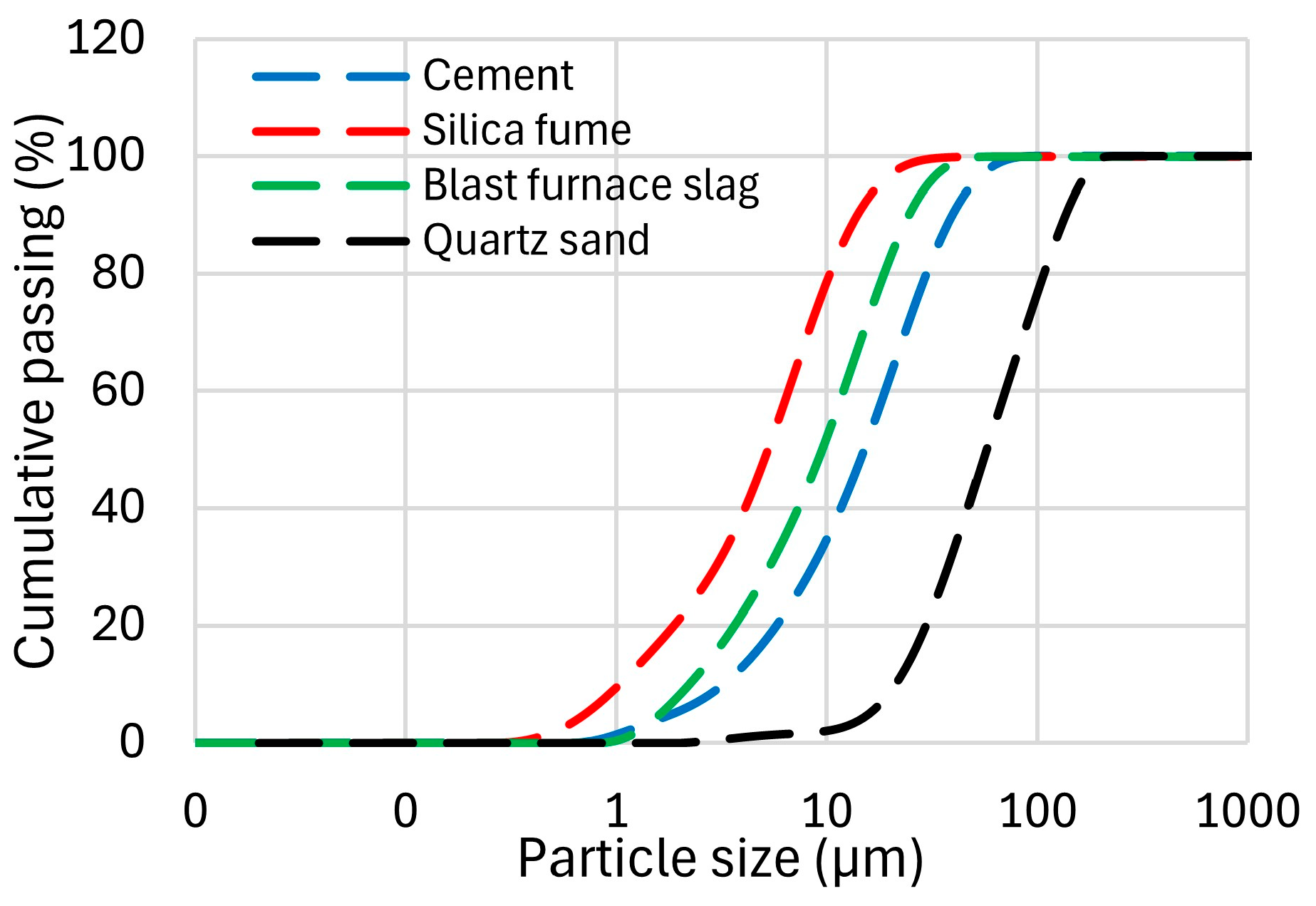
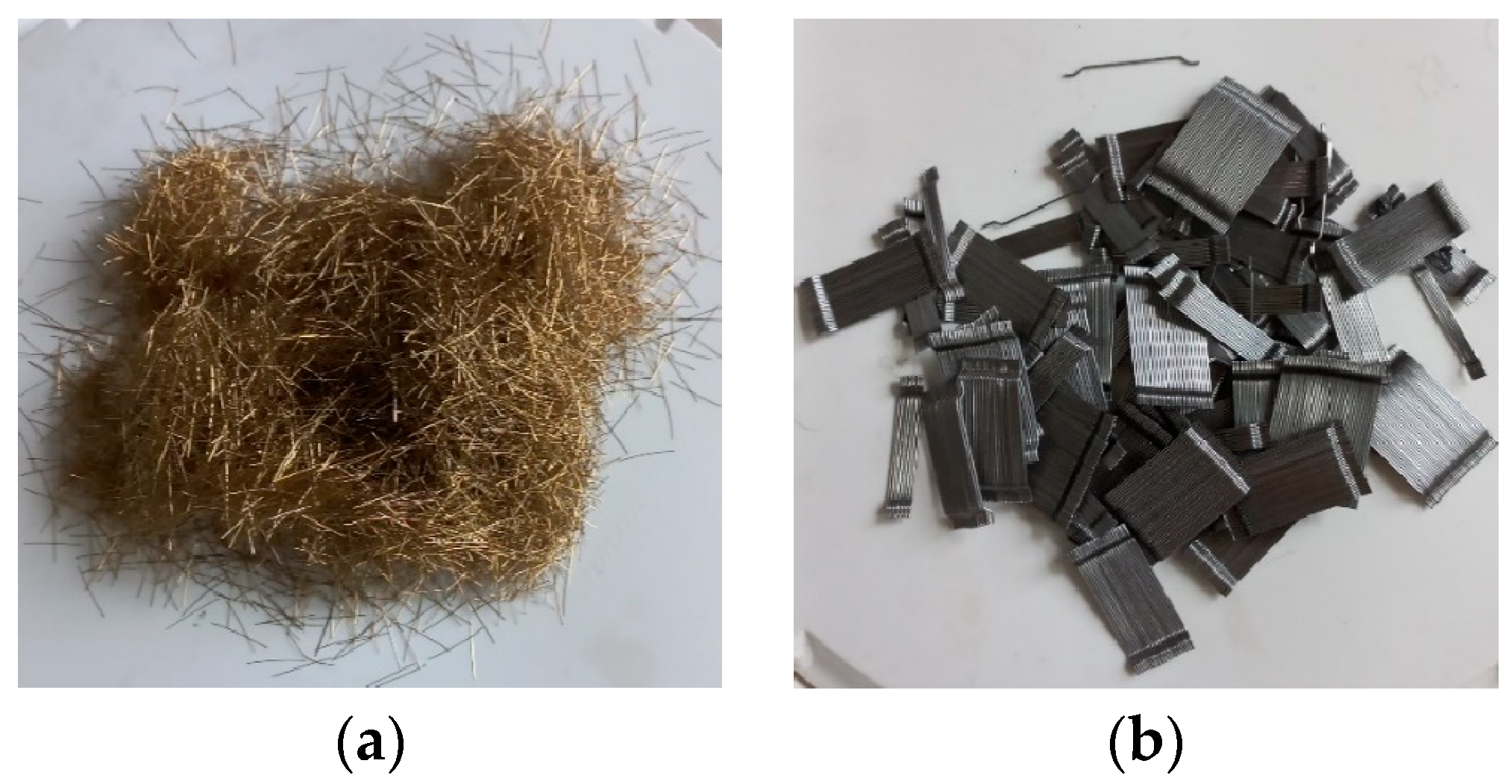
The materials and their quantities used in the UHPC mixtures are listed in Table 1. The binder part of the UHPC consisted of CEM I 42.5 grade Portland cement, silica fume and blast furnace slag. In the particle size analysis, the maximum sizes for silica fume and blast furnace slag were determined to be 52 and 59 microns, respectively. Quartz sand with a maximum particle size of 0.2 mm was utilized as the fine aggregate. In the fiber-reinforced mixtures, steel fibers were added on a volumetric basis relative to the total mixture volume of 1 m3. Since the total mixture volume was kept constant, the fiber volume fraction was accommodated by reducing the corresponding amount of quartz sand, such that the fibers replaced part of the sand content without altering the overall mixture volume. The particle size distributions of the UHPC constituents used in this study are presented in Figure 2. Chemical composition and physical properties of the binder materials are summarized in Table 2. The water-to-binder ratio of the UHPC mixtures was 0.17, and the total fiber volume fractions (Vf) were set at 1% and 2%. These fractions were selected to represent the commonly adopted lower and upper bounds in UHPC research, thereby ensuring both mechanical efficiency and workability [42,43]. Previous studies have shown that content below 1% provide negligible improvements in shear behavior, while fractions higher than 2% may lead to clustering and limited additional benefit [21,27,44,45]. The Mono1.0 and Mono2.0 mixtures contained only straight micro steel fibers, whereas the Hybrid1.0 and Hybrid2.0 mixtures included a 50:50 combination (by volume) of straight micro and hooked-end macro steel fibers (Table 1). This ratio was chosen to provide equal representation of each fiber type, enabling balanced contributions to micro and macro crack control [33,46,47,48,49]. In addition, Control mixture without steel fiber was also prepared. The straight micro and hooked-end macro steel fibers are illustrated in Figure 3, and their properties are summarized in Table 3. It should be noted that straight microfibers are approximately around 25% more expensive than hooked-end macro fibers according to current market prices, which is an important consideration for cost-performance evaluations.

2.2. Test Specimens

The mechanical properties of UHPC mixtures were evaluated in terms of compressive strength, splitting tensile strength, flexural tensile strength and fracture behavior parameters. For each UHPC mixture, six cube specimens with dimensions of 100 × 100 × 100 mm were prepared for axial compression tests to determine compressive strength. Splitting tensile strength was measured on cylinder specimens with dimensions of 100 × 200 mm (diameter × length), with three specimens tested for each mixture [50]. Prismatic beam specimens with dimensions of 150 × 150 × 550 mm were utilized for fracture tests in accordance with the provisions of EN 14651 [51], using three specimens for each mixture. A 2 mm-wide and 25 mm-deep notch was created on the surface, perpendicular to the casting side, at the midspan of the specimens.
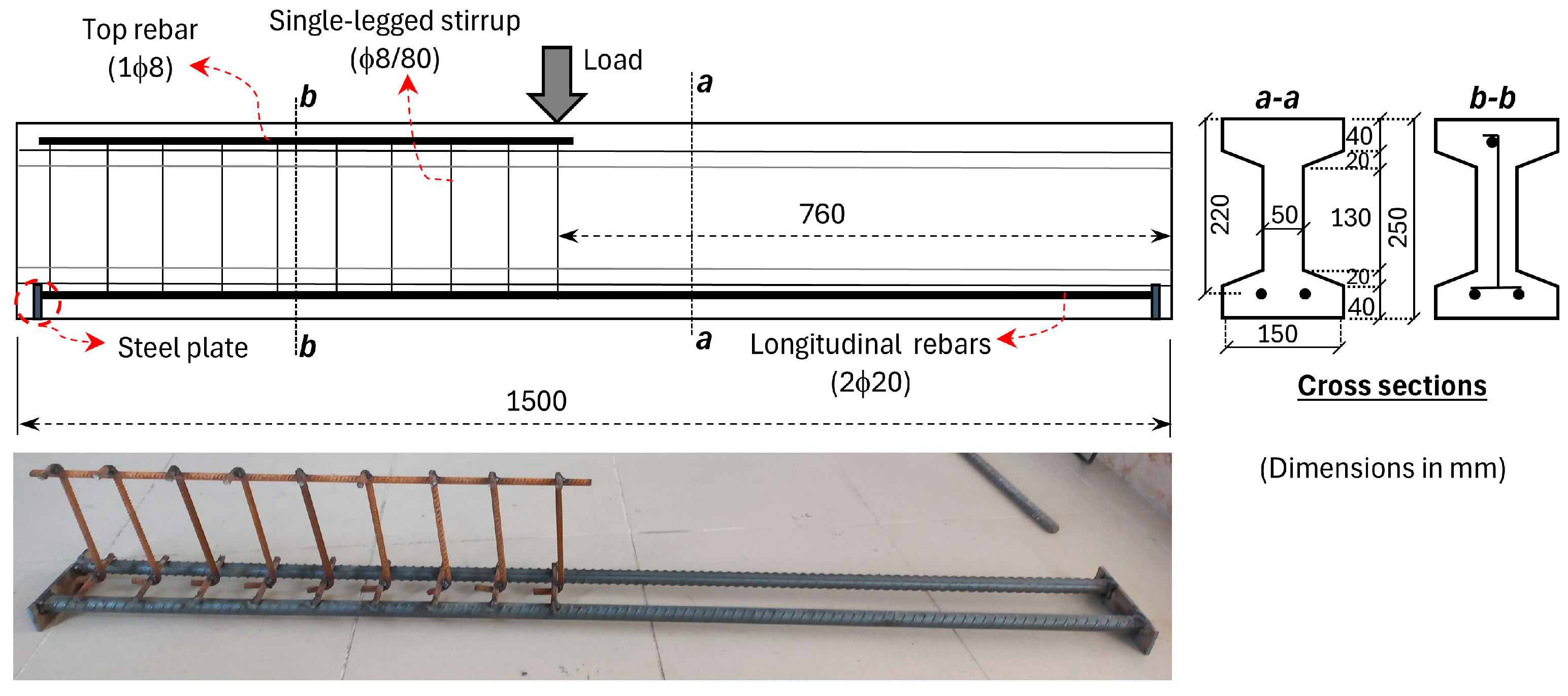
All I-beams had the same cross-sectional dimension of 150 × 250 mm and a total length of 1500 mm. The beams were tested under a three-point loading scheme creating two shear spans. One span was reinforced with single-legged 8 mm (ϕ8) stirrups at 80 mm spacing to prevent shear damage, while no stirrups were provided in other span (Figure 4). This ensured that the shear behavior was localized to the region where the measurements were to be made [25,29,52,53,54,55,56]. The stirrups were welded to the longitudinal rebars at the bottom and to the top rebar (Figure 4). Regarding the shear span-to-depth ratio (a/d), it is well established that a value of 2.5 is generally considered a transition point, below which reinforced concrete beams are prone to shear-critical failure. At very low ratios (a/d < 1.5), beams may develop arch action. For intermediate values (2.5 ≤ a/d ≤ 6), failure is typically governed by flexure-shear of diagonal tension modes following flexural cracking. When a/d exceeds 6, the response is generally governed by flexural behavior [57]. Therefore, a/d ratio of 3.0 was adopted in the present study to avoid arch action and to provide a clearer evaluation of the influence of steel fibers on shear behavior. The beams were reinforced with two longitudinal rebars of 20 mm diameter (ϕ20), corresponding to a reinforcement ratio of 0.057. This considerably high ratio was intentionally employed to promote shear-dominated behavior rather than flexural failure (Figure 4). The average yield and tensile strength of the rebars were 465 MPa and 563 MPa, respectively. To prevent premature bond failure, the endpoints of the tensile rebars were welded to steel plates (Figure 4).

2.3. Mixing Procedure of UHPC and Production of Test Specimens

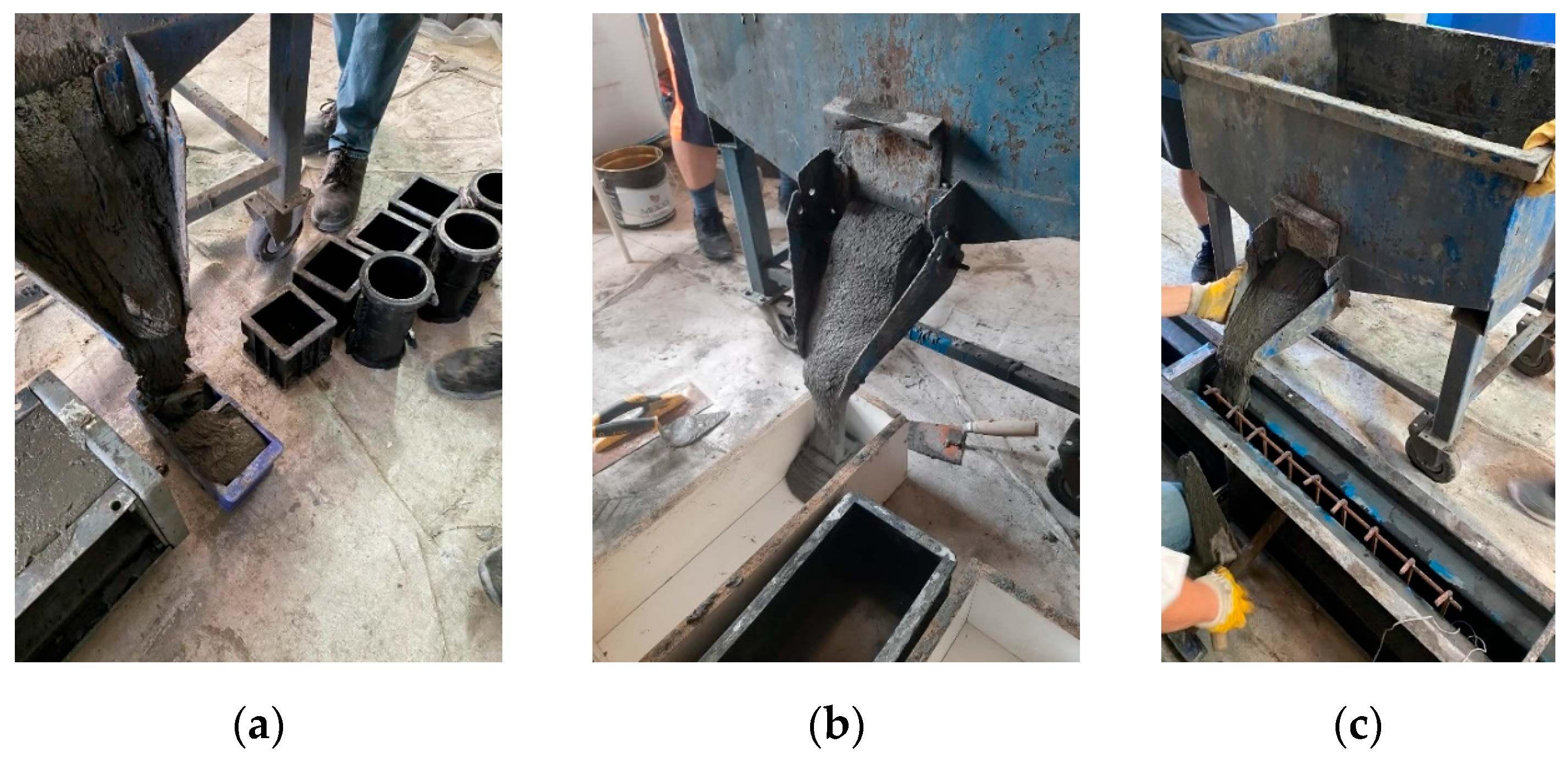
A specially designed pan mixer with a capacity of 100 dm3 was used for the preparation of UHPC mixtures. In the first stage of the UHPC mixing process, all powder components (cement, silica fume, and blast furnace slag) were mixed to ensure uniform particle dispersion, and then water and half of the superplasticizers were gradually added until the mixture reached liquid form. Afterwards, quartz sand was added to the pan mixer. The remaining additive was gradually added to the mixture, and the mixing procedure continued until a fluid consistency was obtained. Steel fibers were directly incorporated into the fresh mixture during the final stage of mixing without pre-dispersion, following a controlled and gradual addition to prevent fiber balling and ensure uniform dispersion. Once all materials were added, the uniform distribution of the fibers and the flow consistency were visually inspected. Subsequently, the concrete was transported to the casting vehicle. For the fabrication of the cube and cylinder specimens, the casting vehicle was positioned directly above the molds, allowing the fresh concrete to flow vertically and fill them under its own wight (Figure 5a). The prismatic beams and I-beams were cast in formwork by positioning the casting vehicle at one end, allowing the concrete to be discharged through the outlet and flow longitudinally along the formwork (Figure 5b,c) [58]. To avoid any adverse influence on fiber distribution, no vibration or shaking table was applied during specimen production. Following casting, all specimens were covered with a plastic sheet to prevent moisture evaporation. After 24 h, the specimens were demolded and stored at ambient laboratory temperature without water curing until the test day.

2.4. Test Setup and Instrumentation

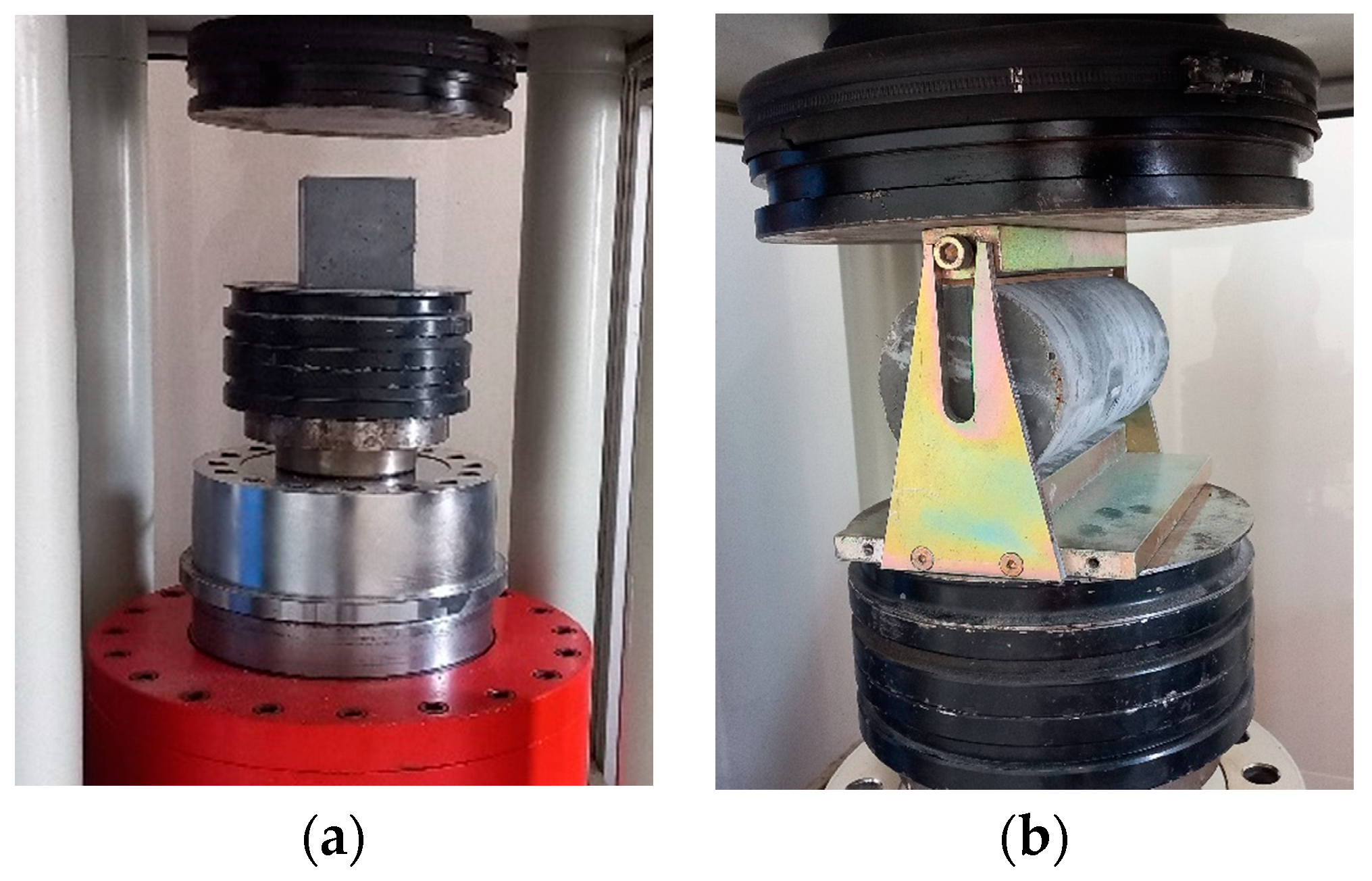
The axial compression and splitting tensile tests were carried out on a hydraulic compression testing machine with a maximum load capacity of 2000 kN. The axial compression tests were conducted under load control in accordance with the EN 12390-3 [59]. The test setup for compression tests is presented in Figure 6a. The splitting tensile tests were performed in accordance with the specifications outlined in EN 12390-6 [60]. The cylindrical specimens were placed horizontally and centered within the loading apparatus, and a linear compression force was applied along the cross-sectional length by means of rigid heads positioned above and below of the specimen (Figure 6b).
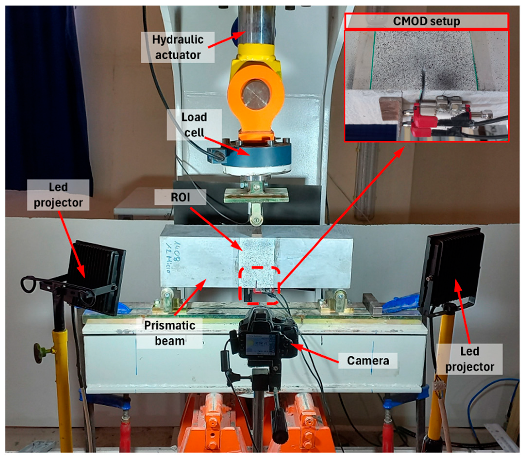
The fracture tests of the prismatic beam specimens were carried out in accordance with the procedures specified in EN 14651 [51]. The prismatic beams were placed on two rotating support cylinders spaced 500 mm apart (Figure 7). The concentrated load was applied at the midspan of simply supported beams through the servo-hydraulic testing machine with a load capacity of 500 kN. The tests were carried out under deformation control with a constant rate of 0.05 mm/min. Two displacement transducers were located at the notch area to measure the crack mouth opening displacement (CMOD) values (Figure 7).
The two-dimensional digital image correlation (2D-DIC) method was employed to examine the deformations that occurred on the surfaces of beam specimens in the fracture tests. Prior to testing, the beam surfaces were prepared by applying a thin layer of matte white spray paint followed by a randomly distributed black speckle pattern to ensure sufficient contrast for image correlation. A digital camera with a resolution of 1024 × 768 pixels and a CMOS sensor (23.2 × 15.4 mm) was positioned at a distance of 0.5 m from the specimen and mounted on a rigid tripod to avoid vibration. Artificial lighting was provided by two LED projectors placed at a 45° angle to minimize shadowing and to eliminate potential variations due to changes in natural light. The region of interest (ROI) was located at the midspan of the beams and covered an area 100 mm wide and 150 mm high (Figure 7). The digital images were taken at 10 s intervals throughout the tests.
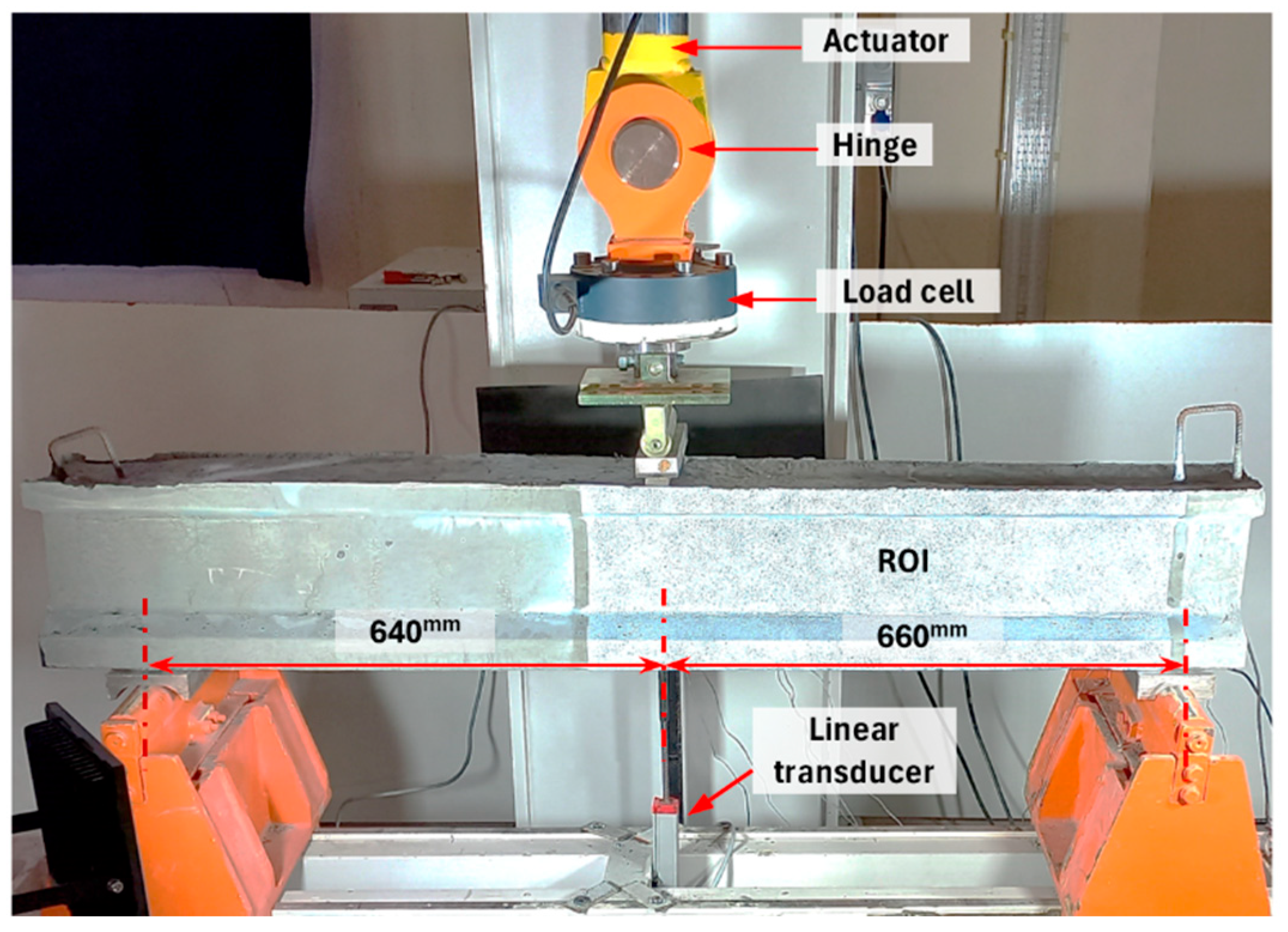
Flexural tests of the I-beams were conducted under a three-point loading configuration using a hydraulic actuator with a loading capacity of 500 kN. The midspan deflection was quantified with a linear transducer having a measuring capacity of 150 mm (Figure 8). Two strain gauges were mounted on both longitudinal rebars to measure the strain values. The tests were carried out under deflection-controlled loading at a rate of 0.5 mm/min. The flexural test setup and instrumentation for the I-beams are shown in Figure 8. Crack initiation and propagation in the I-beams were monitored using 2D-DIC. The same 2D-DIC setup employed in the fracture tests was also adopted for the I-beams. A random speckle pattern was applied over a 750 mm length from the left support, covering the span without stirrups (Figure 8). The digital camera was placed at 1.2 m from the beam surface, with two LED projectors positioned at 45° to ensure uniform artificial lighting [58]. The digital images of this region (ROI) captured at the same rate for the fracture tests. 2D-DIC analyses of both the prismatic beam and the I-beam tests were performed using GOM Correlate software (Version 2019) [61].

3. Experimental Results and Discussion

3.1. Axial Compression and Splitting Tensile Test Results

The average compressive strength (fc) for each mixture was calculated considering 6 cube specimens. The effect of fiber volume fraction (Vf) and hybrid fiber use on compressive strength is presented in Figure 9a. As expected, the incorporation of steel fibers led to an increasing trend in compressive strength compared to the Control mixture without fiber, which exhibited an average compressive strength of 140 MPa. It was found that, compared to the Control mixture, the increase in strength was limited (maximum 11%) for the Mono1.0 and Hybrid1.0 mixtures, whereas a significant increase (approximately 23%) was observed for the mixtures with 2% fiber volume fraction. However, no significant difference in compressive strength was observed between the use of mono and hybrid fiber (Figure 9a).
Splitting tensile tests were performed on 3-cylinder specimens for each UHPC mixture. The variation in average splitting tensile strengths (fct) according to volumetric fiber ratios is shown in Figure 9b. The inclusion of steel fibers led to a substantial increase in splitting tensile strength when compared to the Control mixture, which exhibited an fct of 9 MPa. For the Mono1.0 and Hybrid1.0 mixtures, the fct increased by 1.7 and 2 times, respectively. When the fiber volume fraction was increased to 2.0%, significant improvements of 2.4 and 2.9 times were observed for the mono and hybrid mixtures, respectively. Additionally, hybridization showed approximately 15% higher performance than microfiber use only at both 1% and 2% volume fractions (Figure 9b).

3.2. Fracture Test Results

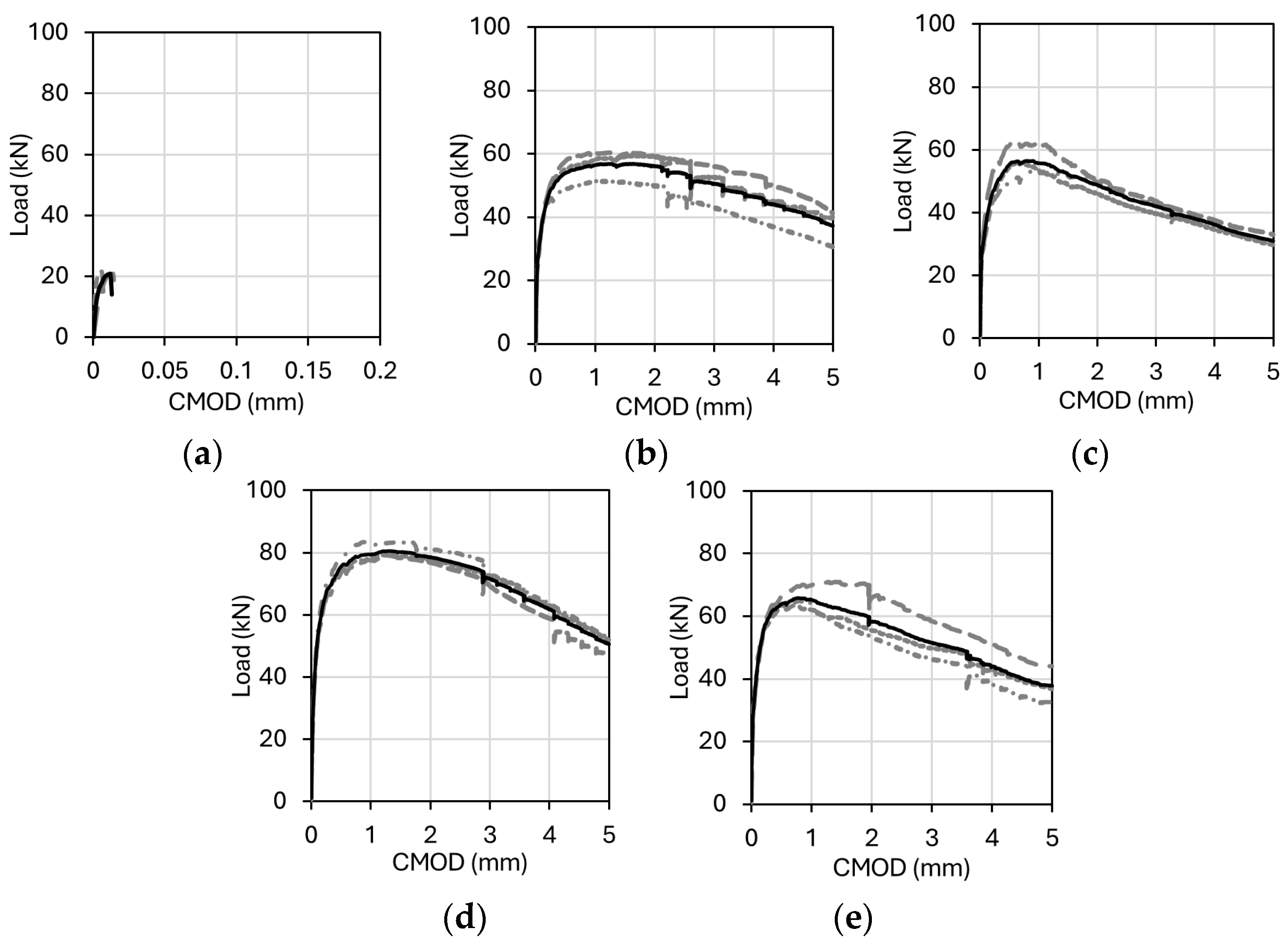
The load vs. CMOD response of the prismatic beam specimens is shown in Figure 10. It was noted that the measurement capacity of the transducers permitted the acquisition of data up to 5 mm. The CMOD values were calculated by averaging the measurements obtained from two transducers placed at the notch area of the specimens. The average load vs. CMOD responses indicated by the bold lines were obtained from three specimens for each mixture (Figure 10). Using the average load vs. CMOD curves, residual flexural tensile strengths (fR,j) of UHPC mixtures were calculated using Equation (1) in accordance with EN 14651 [51]. In Equation (1), P denotes the applied force at midspan, L is the span length, b is the beam width and hsp is the section height excluding the notch depth [51].
The fR,j values are defined as the characteristic strengths (j = 1, 2, 3, 4) corresponding to the CMOD values of 0.5, 1.5, 2.5 and 3.5 mm specified in EN 14651 [51], respectively. The flexural tensile strength at cracking (fLOP) was calculated from the cracking load using Equation (1). In addition, maximum strength (fR,max) was also determined. The flexural tensile strengths are summarized in Table 4 for each UHPC mixture. In all prismatic beams with fibers, a slope change occurred due to stiffness degradation after cracking; however, the strength continued to increase until the peak load owing to the crack bridging ability of the steel fibers. This response is characterized as deflection-hardening behavior [62].
f R , j = 3 P L 2 b h s p 2
A comparison of the average flexural tensile strengths of the UHPC mixtures revealed no significant difference in terms of cracking strength (fLOP) in general. However, the use of 2.0% microfiber by volume resulted in approximately a 10% increase in strength compared to the Control mixture (Table 4). While no significant difference was observed between the maximum strengths of the Mono1.0 and Hybrid1.0 mixtures, the use of 2.0% straight micro steel fiber led to a 22% higher strength than the corresponding hybrid combination. A higher proportion of straight microfiber in the pre-peak region, where crack widths are limited, is effective in enhancing strength capacity. This outcome may be attributed to the efficiency of microfibers at higher volume fractions. Due to their smaller length, straight microfibers are more numerous and tend to be better oriented and uniformly dispersed within the matrix, thereby improving their ability to bridge fine cracks. Consequently, the contribution of mono fiber use can, under certain conditions, outweigh that of hybrid combinations. Similar findings have been reported in the literature, where mono fiber use, particularly microfibers, was found to outperform hybrid combinations [32,38,40].
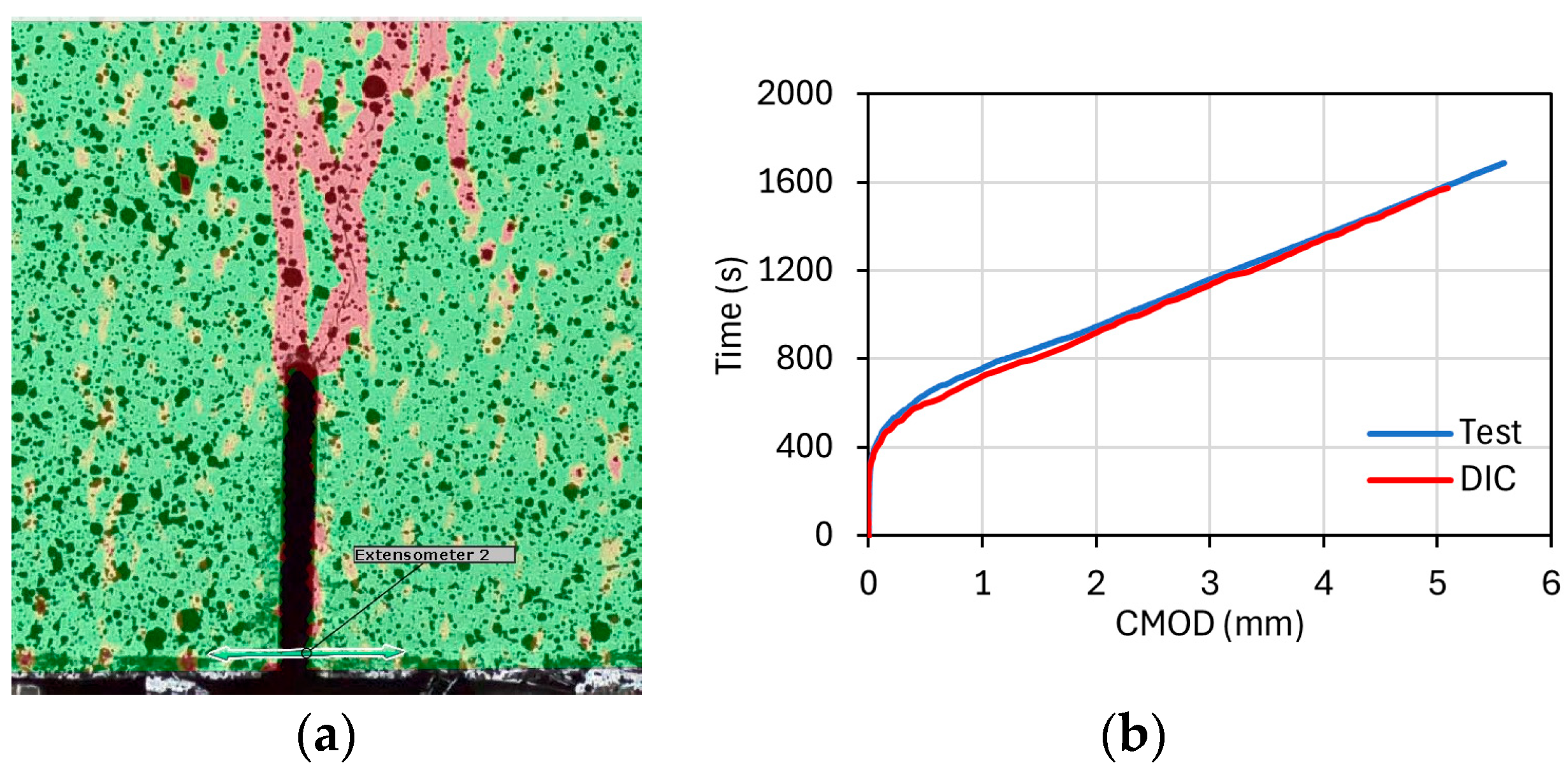
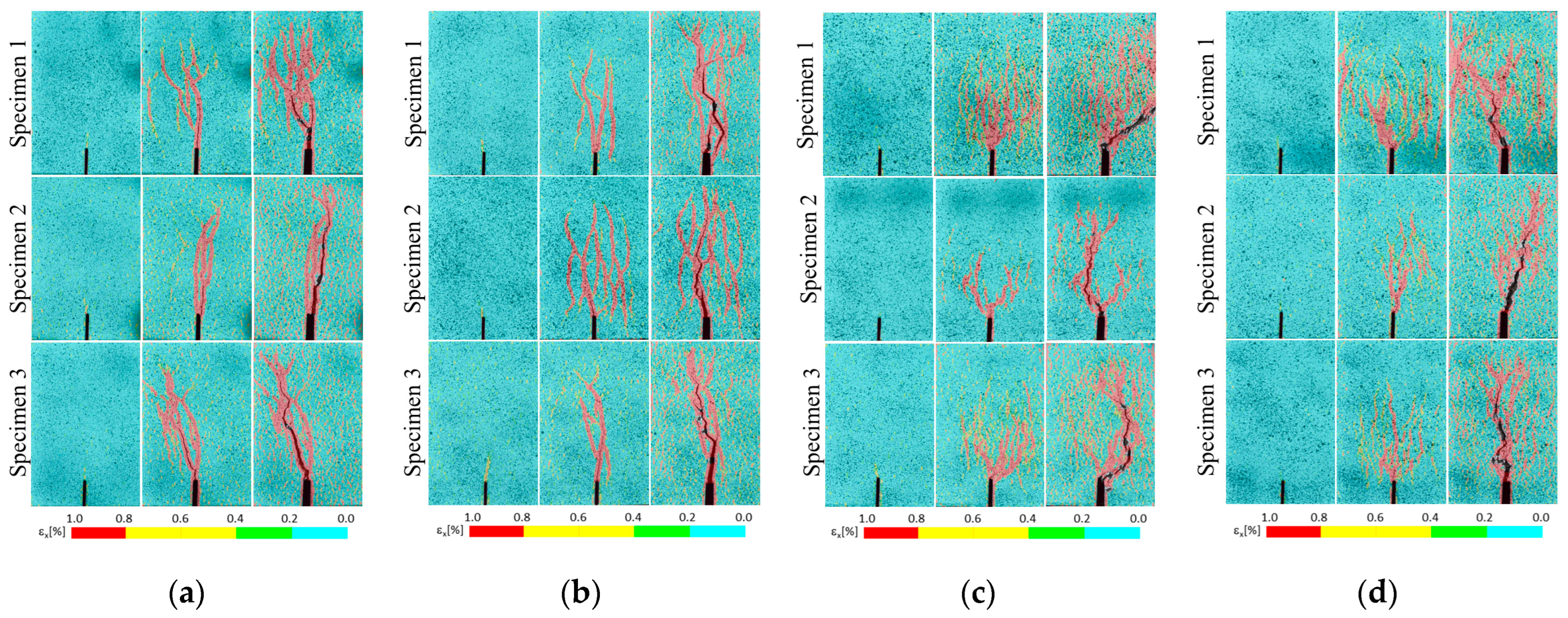
The influence of steel fiber hybridization on the fracture behavior of UHPC mixtures was evaluated using 2D-DIC analysis. To determine the CMOD values using 2D-DIC, a virtual extensometer was placed at the crack mouth, and the time vs. CMOD relationship was recorded (Figure 11a). For calibration of the analysis parameters, the experimental time vs. CMOD curve was compared with the analytical results. An example of the agreement between experimental and analytical results is presented in Figure 11b. GOM Correlate [61] software was used to determine the strains in the lateral direction (εx) in order to visualize the crack propagation. Figure 12 shows the lateral strain (εx) contours of the prismatic beams at different stages, from left to right: cracking load, peak load and end of the test at a CMOD of 5 mm. Even though there were no visible cracks at the cracking point, 2D-DIC could be used to visualize this early phase of the tests. Although fiber content had no significant effect on crack propagation, crack openings were notably narrower in specimens containing only straight microfibers. Compared to mono fiber mixtures, hybrid fiber use showed an average 37% reduction in CMOD values at maximum load (Table 4).

3.3. Test Results of I-Beams

3.3.1. Cracking Patterns and Failure Modes

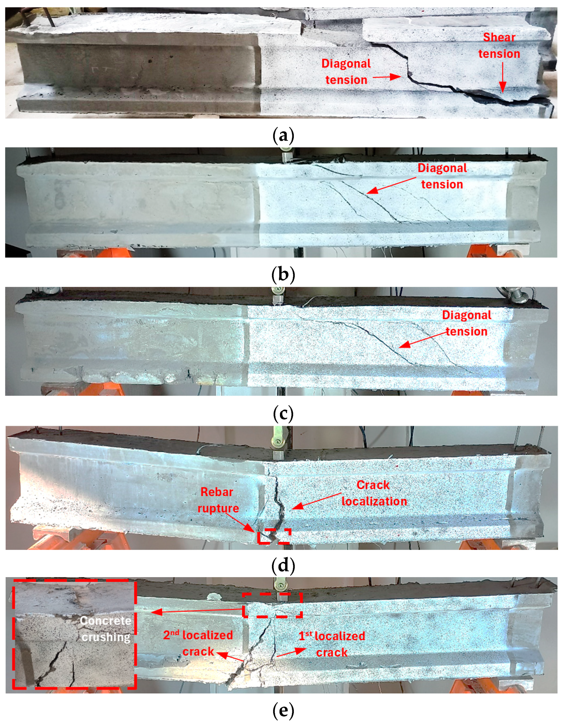
Figure 13 presents a comparison of the failure modes for the I-beams. The Control beam failed after the formation of the critical shear crack, which was initiated by a single inclined crack in the mid-depth region and propagated between the loading point and the rebars (Figure 13a). This failure mode can be described as diagonal tension combined with shear tension failure, where the diagonal crack propagated along the rebars toward the support. The failure was very brittle with no apparent sign of failure and the section above the crack was completely separated from the web (Figure 13a). The diagonal tension-type shear failure was observed in the Mono1.0 and Hybrid1.0 beams, without concrete crushing in the compression zone prior to rebar yielding (Figure 13b,c). The failure was not catastrophic as in the Control beam, owing to the crack-bridging ability of the steel fibers.
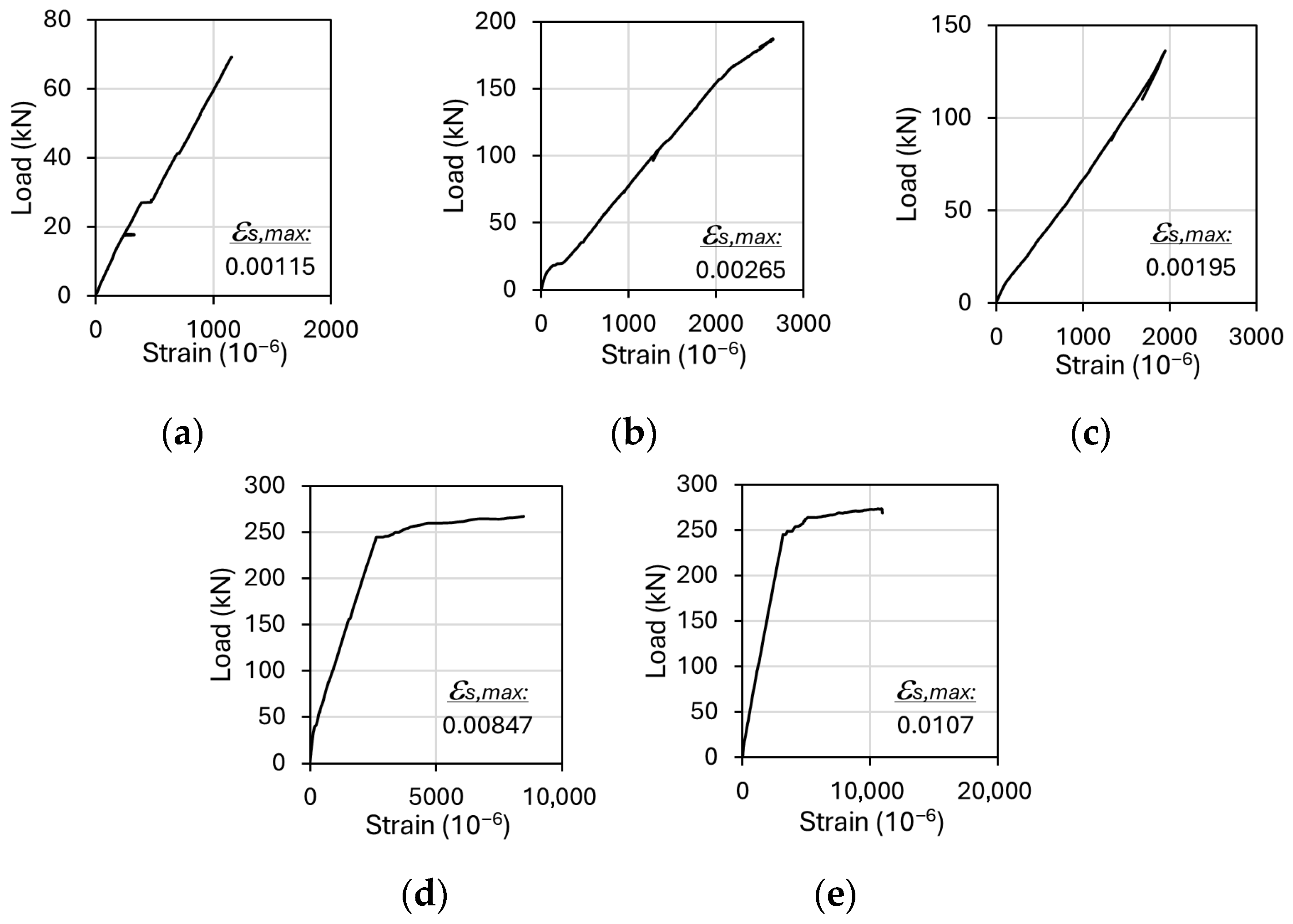
Ductile flexural behavior was observed in beams containing 2.0% steel fibers by volume, with no significant signs of shear damage. This finding is consistent with previous studies reporting that incorporating 2.0% steel fibers in UHPC beams can prevent shear failure even without shear reinforcement [17,63]. In the Mono2.0 beam, the deformation on the rebar was concentrated at a single point due to the crack localization and this caused rebar rupture resulting in excessive strain values (Figure 13d). In previous studies, rebar rupture type flexural failures were observed for the UHPC beams despite the high reinforcement ratios [64,65]. The Hybrid2.0 beam failed due to concrete crushing. In this case, the formation of an additional localized crack reduced the concentration of strain in the rebars, and consequently no rebar rupture was observed (Figure 13e).
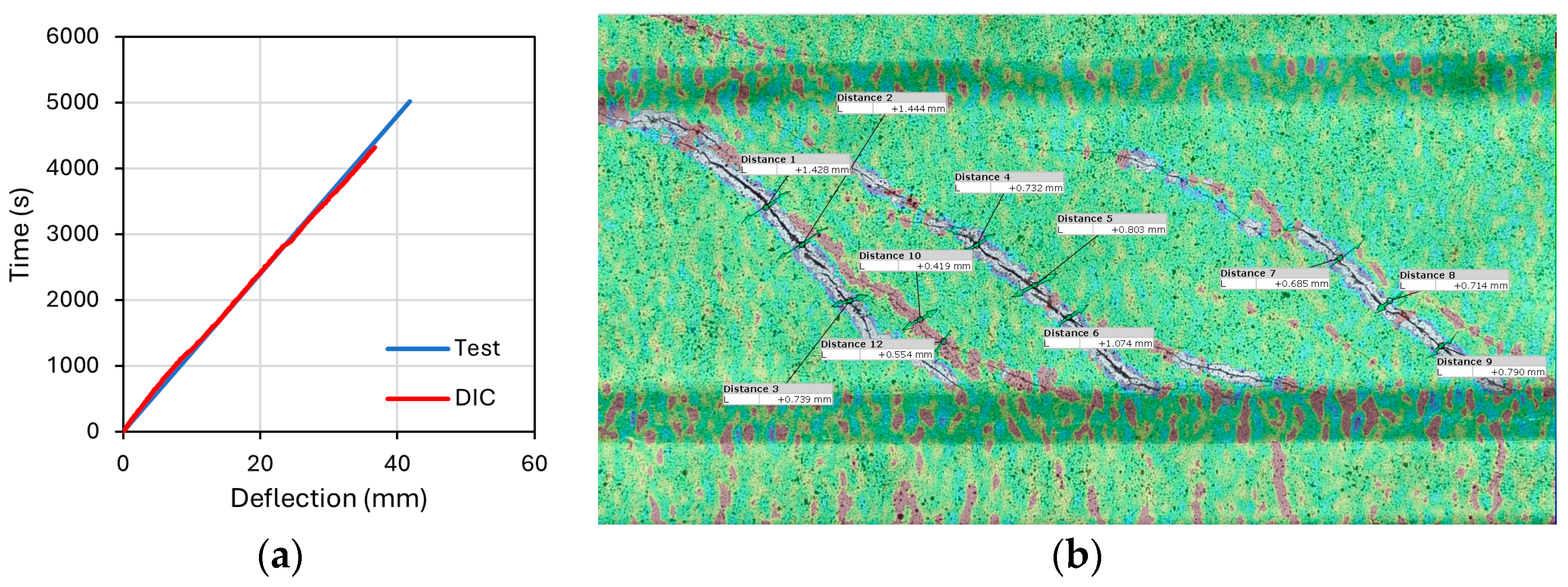
The crack development of I-beams was investigated by 2D-DIC analyses performed with the GOM Correlate [61] software. The experimentally measured time vs. deflection data were compared with the analytical results to assess the accuracy of the DIC analysis. Figure 14a presents time vs. deflection curve for the Mono2.0 beam, illustrating both the experimental and analytical outcomes. The deformation measurements can be made using virtual gauges during the image acquisition stages of the tests. Figure 14b illustrates a representative example of virtual extensometers used to monitor crack widths during the tests.
In order to evaluate the influence of varying steel fiber contents on cracking behavior, the shear cracks were determined through 2D-DIC analysis at peak and ultimate load levels (Figure 15). The evaluation of the crack widths up to the peak load is presented in Figure 16. At equivalent load levels, the use of steel fibers effectively limited crack propagation, as expected. Figure 16 shows that straight micro steel fibers were more effective than hybrid combination in controlling crack widths. In addition, multiple crack formations were also observed in beams with steel fiber (Figure 15). This can be attributed to distinct crack-bridging behavior of the fibers. In the pre-peak region, where diagonal crack openings remained small, straight microfibers provided effective bridging effect because of their higher number density per unit volume. By contrast, the contribution of hooked-end fibers became more pronounced as crack openings grew larger. Consequently, at the same total fiber volume, incorporating hooked-end fibers into the hybrid mixture reduced the microfiber count and diminished crack control up to peak load. Similar trends have been reported, where the use of microfibers matched or even outperformed hybrid fiber reinforcement at comparable dosages [30,32,38,66,67,68].
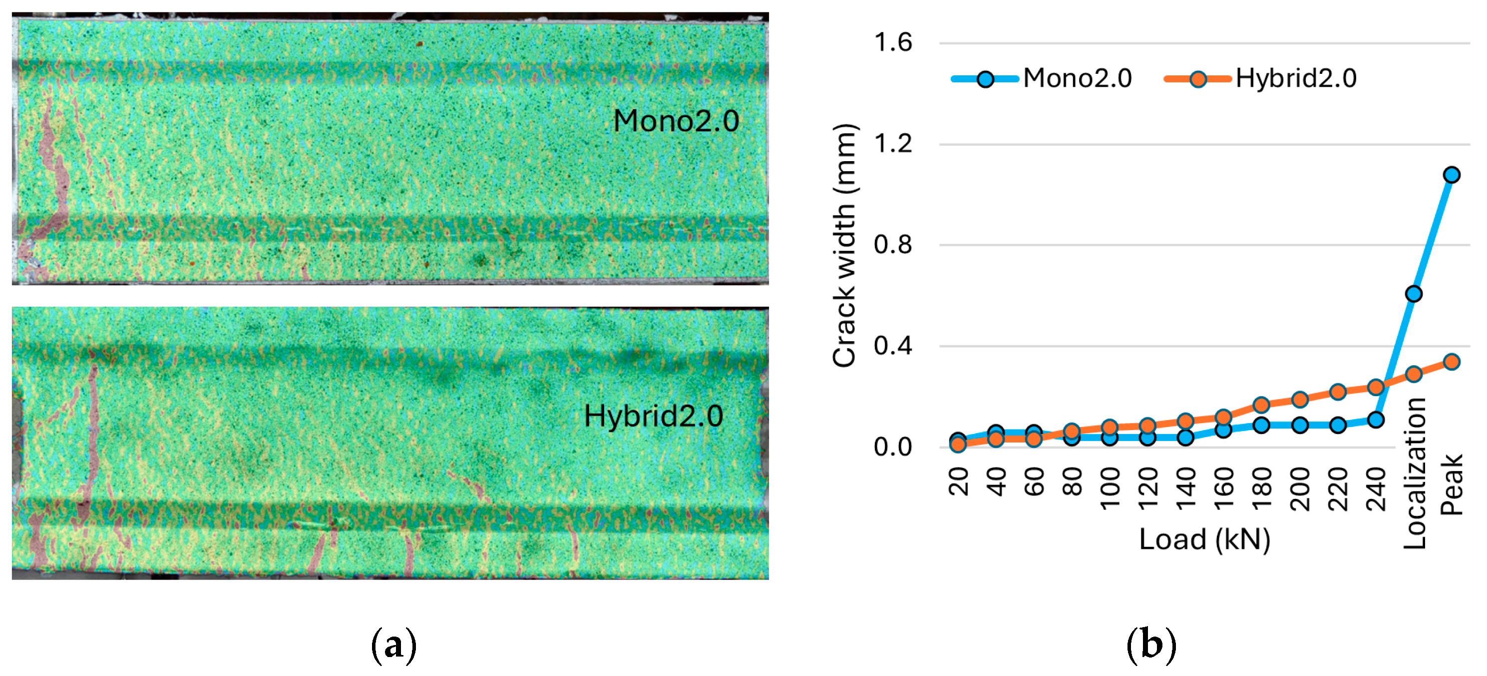
Figure 17 shows the cracking patterns of the Mono2.0 and Hybrid2.0 beams at the peak load, along with an evaluation of their maximum crack widths. Both beams exhibited multiple cracking, followed by crack localization (Figure 17a). However, it was observed that crack widths, aside from the critical crack in beam Mono2.0, remained quite limited. Following crack localization, crack widths gradually increased due to fiber pull-out, while the development of other cracks stopped (Figure 17b).

3.3.2. Load vs. Deflection Response

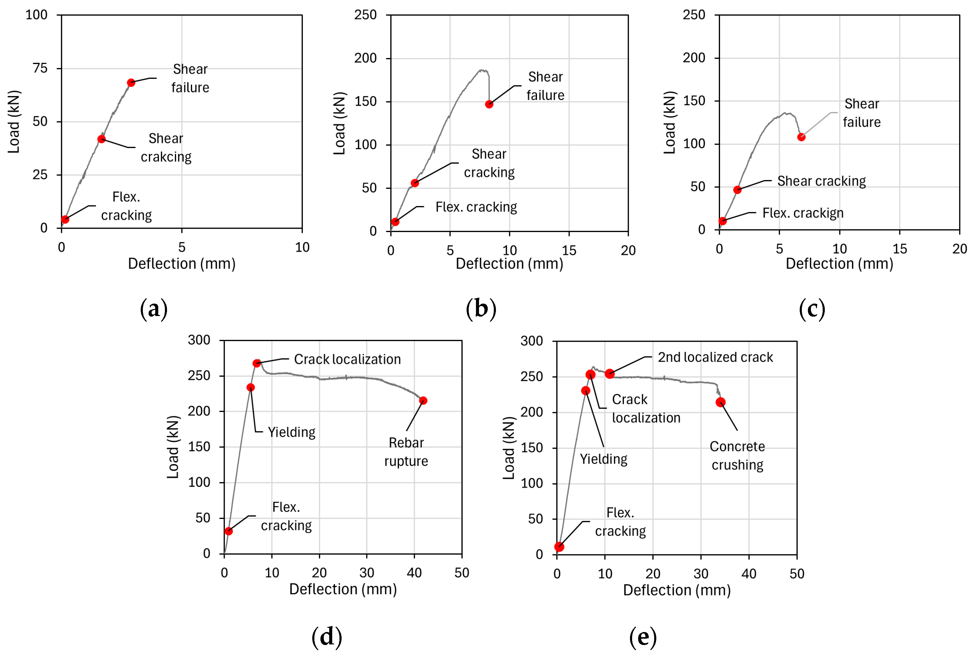
The experimental load vs. midspan deflection curves of the I-beams subjected to three-point loading are presented in Figure 18. The strain gauge readings obtained from the longitudinal rebars are presented in Figure 19 including the average maximum measurable strain values (εs,max). Flexural cracking load (Pcr,flex), shear cracking load (Pcr,shear), yield load (Py), peak load (Pp), ultimate load (Pu) and corresponding midspan deflection values are summarized in Table 5. The use of 1% fiber by volume significantly increased the flexural cracking strength compared to the non-fiber condition, whereas its effec on shear cracking strength was limited. Although shear failure also occurred in the Mono1.0 and Hybrid 1.0 beams, their load capacities increased by 2.7 and 2.0 times, respectively, compared to the Control beam. Similarly, incorporating mono and hybrid steel fibers at 1% by volume enhanced the deflection capacity by 2.7 and 1.9 times, respectively (Table 5). Moreover, the Mono1.0 beam exhibited a 37% higher shear strength than the Hybrid1.0 beam. It was found that the impact of the synergetic effect between the different steel fibers in terms of shear strength was limited compared to the mono fiber use, which can be attributed to the higher efficiency of microfibers in controlling fine crack openings in the pre-peak region due to their greater numerical density. As also pointed out in the previous studies, straight microfibers demonstrated superior efficiency in crack control and shear resistance compared to longer hooked-end fibers [17,69]. These studies showed that microfibers provide a more uniform distribution, enhance the initial shear cracking load, and effectively restrain shear crack propagation, whereas hooked-end fibers are less efficient and often associated with wider crack openings. In this context, the reduced proportion of microfibers in the hybrid mixtures likely diminished their beneficial influence, which explains the relatively lower shear performance of the Hybrid1.0 beam compared to the Mono1.0 beam.
Beams containing 2.0% fiber by volume reached their load-carrying capacity without significant strength loss (Figure 18d,e). Although the flexural cracking strength of the Hybrid2.0 beam was comparable to that of beams containing 1% fiber by volume, the Mono2.0 beam exhibited a strength approximately 2.8 times higher than the Hybrid2.0 beam. Following flexural cracking, the beams continued to carry increasing loads with reduced stiffness until the rebar yielding. Thereafter, one of the flexural cracks developed excessively, a phenomenon referred to as crack localization. The crack localization point was identified as the stage at which one of the crack openings, monitored incrementally through 2D-DIC analysis, began to increase disproportionately (Figure 18d,e). The load-carrying capacity values for Mono2.0 and Hybrid2.0 were 273.33 kN and 264.56 kN, respectively (Table 5). Afterward, the strength began to decrease due to fiber debonding induced by excessive crack openings and limited concrete damage in the compression zone. It was also observed that strain hardening of the rebars could not compensate for the strength loss. In the Mono2.0 beam, failure occurred with rebar rupture following a 21% load drop. In contrast, the Hybrid2.0 beam exhibited progressive concrete damage beyond the peak load, which led to crushing failure and a 19% reduction in strength. A comparison of the load-carrying and deflection capacities of the Mono2.0 and Hybrid2.0 beams revealed no significant differences in flexural behavior.

4. Conclusions and Recommendations

The influence of hybrid steel fiber reinforcement on the shear behavior of Ultra-High-Performance Concrete (UHPC) was experimentally investigated using I-shaped beams. In addition, the effect of steel fiber hybridization was assessed at the material scale in terms of strength and fracture behavior. Based on the experimental results and the 2D-DIC analyses in the study, the following conclusions were drawn:
  • The addition of 1% and 2% steel fibers by volume led to increases of approximately 11% and 23% in compressive strength, respectively, compared to the Control mixture without fibers. However, hybrid fiber reinforcement had no significant influence on compressive strength. In contrast, steel fiber incorporation produced a more pronounced effect on splitting tensile strength. At a fiber volume fraction of 2%, the splitting tensile strength increased by up to three times relative to the Control mixture. Moreover, hybrid fiber combinations provided a greater enhancement in splitting tensile strength than mixtures reinforced only microfibers, highlighting that the benefits of fiber addition were more evident in tensile behavior than in compression.
  • The fracture test results revealed no significant difference in cracking strength. As expected, the inclusion of steel fibers led to notable improvements in residual flexural strength. However, no significant synergistic effect was observed between different types of steel fibers at a total fiber volume of 1%. At 2.0% fiber volume, the use of straight microfibers resulted in a 22% higher strength compared to hybrid fiber combination.
  • The Control beam exhibited brittle shear failure characterized by a single diagonal crack. In contrast, UHPC beams with 1% steel fiber by volume developed multiple cracks with reduced widths, resulting in a more distributed damage pattern. The Mono1.0 and Hybrid1.0 beams exhibited diagonal tension-type shear failure without concrete crushing in the compression zone prior to rebar yielding. These failures were not catastrophic as that of the Control beam, owing to the crack-bridging ability of the steel fibers. Microfibers proved more effective than hybrid combinations in controlling crack widths and delaying the propagation of critical shear cracks.
  • Although beams with 1% fiber by volume eventually failed in shear, both their shear strength and deflection capacity were substantially improved. The Mono1.0 beam exhibited increases of 2.7 times in both shear strength and deflection capacity, whereas the Hybrid1.0 beam showed respective improvements of 2.0 and 1.9 times compared to the Control beam. Moreover, the Mono1.0 beam achieved a 37% higher shear strength than the Hybrid1.0 beam and reached the highest load capacity, confirming the dominant role of microfibers in enhancing pre-peak stiffness and delaying shear localization. Although the Hybrid1.0 beam performed better than the Control beam, its load capacity remained lower than that of the Mono1.0 beam, indicating that the synergy between straight microfibers and hooked-end macrofibers was not fully mobilized at 1% dosage.
  • At 2% fiber dosage, the dominant failure mode shifted from shear to flexural, indicating that a sufficiently high fiber content can transform the structural response by providing adequate crack-bridging capacity and shear resistance. Following the initiation of flexural cracking, the beams continued to carry increasing loads with reduced stiffness until the reinforcement. Thereafter, one of the flexural cracks exhibited excessive widening, a phenomenon known as crack localization. A comparison between the Mono2.0 and Hybrid2.0 beams revealed no significant differences in either load-carrying or deflection capacities, confirming their similar flexural behavior.
  • The use of only microfibers provided a noticeable increase in shear strength compared to the hybrid mixture; however, it was still insufficient to prevent shear failure at a 1% fiber dosage. When the fiber content was increased to 2%, shear failure was avoided in both microfiber and hybrid fiber-reinforced beams. Since similar strength values were achieved at this dosage, the use of hybrid fibers may offer a potential economic advantage by reducing their reliance on the more expensive microfibers.
The results of this experimental study indicated that, for the investigated volumetric ratios, the hybridization of different steel fiber types was less effective than the use of mono fibers in UHPC I-beams. However, it should be noted that the hybrid steel fiber combinations examined in this study were limited in terms of fiber types and volume fractions. Considering previous studies that have highlighted the potential benefits of hybrid fiber reinforcement in UHPC, further research incorporating a wider range of fiber combinations is recommended. Although the presented study focused on two representative fiber volume fractions, future investigations should also address intermediate dosages which may provide additional insight into the transition of structural performance, particularly with respect to shear behavior.

Author Contributions

Conceptualization, T.B. and A.A.; methodology, T.B.; software, T.B. and A.A.; validation, T.B., A.A. and A.Y.; formal analysis, A.A.; investigation, T.B. and A.A.; resources, A.Y.; data curation, A.A.; writing—original draft preparation, T.B.; writing—review and editing, T.B. and A.Y.; visualization, T.B. and A.A.; supervision, T.B. and A.Y.; project administration, T.B. and A.Y.; funding acquisition, T.B. All authors have read and agreed to the published version of the manuscript.

Funding

This research received no external funding.

Data Availability Statement

The data presented in this study is available on request from the corresponding author.

Conflicts of Interest

The authors declare no conflicts of interest.

References

  1. Richard, P.; Cheyrezy, M. Composition of reactive powder concretes. Cem. Concr. Res. 1995, 25, 1501–1511. [Google Scholar] [CrossRef]
  2. Wille, K.; Naaman, A.E.; El-Tawil, S.; Parra-Montesinos, G.J. Ultra-high performance concrete and fiber reinforced concrete: Achieving strength and ductility without heat curing. Mater. Struct. 2012, 45, 309–324. [Google Scholar] [CrossRef]
  3. Wille, K.; El-Tawil, S.; Naaman, A.E. Properties of strain hardening ultra high performance fiber reinforced concrete (UHP-FRC) under direct tensile loading. Cem. Concr. Compos. 2014, 48, 53–66. [Google Scholar] [CrossRef]
  4. Tahwia, A.M.; Elgendy, G.M.; Amin, M. Durability and microstructure of eco-efficient ultra-high-performance concrete. Constr. Build. Mater. 2021, 303, 124491. [Google Scholar] [CrossRef]
  5. Wu, Z.; Shi, C.; He, W.; Wu, L. Effects of steel fiber content and shape on mechanical properties of ultra high performance concrete. Constr. Build. Mater. 2016, 103, 8–14. [Google Scholar] [CrossRef]
  6. Shen, X.; Brühwiler, E. Influence of local fiber distribution on tensile behavior of strain hardening UHPFRC using NDT and DIC. Cem. Concr. Res. 2020, 132, 106042. [Google Scholar] [CrossRef]
  7. Lao, J.; Xu, L.; Huang, B.; Dai, J.; Shah, S.P. Strain-hardening ultra-high-performance geopolymer concrete (UHPGC): Matrix design and effect of steel fibers. Compos. Commun. 2022, 30, 101081. [Google Scholar] [CrossRef]
  8. Guo, Y.Q.; Wang, J.Y.; Gu, J.B. Nonlinear inverse analysis for predicting the tensile properties of strain-softening and strain-hardening UHPFRC. Materials 2022, 15, 3067. [Google Scholar] [CrossRef]
  9. Yoo, D.Y.; Lee, J.H.; Yoon, Y.S. Effect of fiber content on mechanical and fracture properties of ultra high performance fiber reinforced cementitious composites. Compos. Struct. 2013, 106, 742–753. [Google Scholar] [CrossRef]
  10. Li, V.C.; Ward, R.; Hamza, A.M. Steel and synthetic fibers as shear reinforcement. ACI Mater. J. 1992, 89, 499–508. [Google Scholar] [CrossRef]
  11. Lim, D.H.; Oh, B.H. Experimental and theoretical investigation on the shear of steel fiber reinforced concrete beams. Eng. Struct. 1999, 21, 937–944. [Google Scholar] [CrossRef]
  12. Choi, K.; Park, H.G.; Wight, J.K. Shear strength of steel fiber-reinforced concrete beams without web reinforcement. ACI Struct. J. 2007, 104, 12–22. [Google Scholar] [CrossRef] [PubMed]
  13. Pansuk, W.; Nguyen, T.N.; Sato, Y.; Uijl, J.D.; Walraven, J. Shear capacity of high performance fiber reinforced concrete I-beams. Constr. Build. Mater. 2017, 157, 182–193. [Google Scholar] [CrossRef]
  14. Mészöly, T.; Randl, N. Shear behavior of fiber-reinforced ultra-high performance concrete beams. Eng. Struct. 2018, 168, 119–127. [Google Scholar] [CrossRef]
  15. Kodur, V.; Solhmirzaei, R.; Agrawal, A.; Aziz, E.M.; Soroushian, P. Analysis of flexural and shear resistance of ultra high performance fiber reinforced concrete beams without stirrups. Eng. Struct. 2018, 174, 873–884. [Google Scholar] [CrossRef]
  16. Hasgul, U.; Yavas, A.; Birol, T.; Turker, K. Steel fiber use as shear reinforcement on I-shaped UHP-FRC beams. Appl. Sci. 2019, 9, 5526. [Google Scholar] [CrossRef]
  17. Yavas, A.; Hasgul, U.; Turker, K.; Birol, T. Effective fiber type investigation on the shear behavior of ultrahigh-performance fiber-reinforced concrete beams. Adv. Struct. Eng. 2019, 22, 1591–1605. [Google Scholar] [CrossRef]
  18. Yavas, A.; Goker, C.O. Impact of reinforcement ratio on shear behavior of I-shaped UHPC beams with and without fiber shear reinforcement. Materials 2020, 13, 1525. [Google Scholar] [CrossRef]
  19. Ma, K.; Ma, Y.; Liu, B. Experimental investigation on ultra high performance fiber reinforced concrete beams. Mech. Adv. Mater. Struct. 2023, 30, 1155–1171. [Google Scholar] [CrossRef]
  20. Hasgul, U.; Yavas, A.; Birol, T. Replacement of stirrups by steel fibers in shear dominant UHPFRC beams. Turk. J. Civ. Eng. 2023, 34, 103–124. [Google Scholar] [CrossRef]
  21. Xu, Q.; Zhu, Y.; Wang, J.; Sebastian, W. Effectiveness and response of replacing web reinforcements with steel fibers reinforced in shear for non-stirrup UHPC beams. Eng. Struct. 2023, 288, 116168. [Google Scholar] [CrossRef]
  22. Li, P.; Cheng, Q.; Chen, N.; Tian, Y.; Fang, J.; Jiang, H. Experimental Study on Shear Behavior of Non-Stirrup Ultra-High Performance Concrete Beams. Materials 2023, 16, 4177. [Google Scholar] [CrossRef]
  23. Deng, B.; Zhang, L.; Wu, S.; Jiang, H.; Tian, Y.; Fang, J.; Zhou, C. Shear Behavior of Non-Stirrup Ultra-High-Performance Concrete Beams: Contribution of Steel Fibers and UHPC. Buildings 2024, 14, 2705. [Google Scholar] [CrossRef]
  24. Zhang, L.; Deng, B.; He, B.; Jiang, H.; Xiao, J.; Tian, Y.; Fang, J. Experimental investigation on shear behavior of non-stirrup UHPC beams under larger shear span–depth ratios. Buildings 2024, 14, 1374. [Google Scholar] [CrossRef]
  25. Zagon, R.; Matthys, S.; Kiss, Z. Shear behaviour of SFR-UHPC I-shaped beams. Constr. Build. Mater. 2016, 124, 258–268. [Google Scholar] [CrossRef]
  26. Ţibea, C.; Bompa, D.V. Ultimate shear response of ultra-high-performance steel fibre-reinforced concrete elements. Arch. Civ. Mech. Eng. 2020, 20, 49. [Google Scholar] [CrossRef]
  27. Wang, Q.; Song, H.L.; Lu, C.L.; Jin, L.Z. Shear performance of reinforced ultra-high performance concrete rectangular section beams. Structures 2020, 27, 1184–1194. [Google Scholar] [CrossRef]
  28. Banthia, N.; Gupta, R. Hybrid fiber reinforced concrete (HyFRC): Fiber synergy in high strength matrices. Mater. Struct. 2004, 37, 707–716. [Google Scholar] [CrossRef]
  29. Lakavath, C.; Bhosale, A.B.; Prakash, S.S.; Sharma, A. Effectiveness of hybrid fibers on the fracture and shear behavior of prestressed concrete beams. Fibers 2022, 10, 26. [Google Scholar] [CrossRef]
  30. Kim, D.J.; Park, S.H.; Ryu, G.S.; Koh, K.T. Comparative flexural behavior of hybrid ultra high performance fiber reinforced concrete with different macro fibers. Constr. Build. Mater. 2011, 25, 4144–4155. [Google Scholar] [CrossRef]
  31. Ryu, G.S.; Kang, S.T.; Park, J.J.; Koh, K.T.; Kim, S.W. Mechanical behavior of UHPC (ultra high performance concrete) according to hybrid use of steel fibers. Adv. Mater. Res. 2011, 287, 453–457. [Google Scholar] [CrossRef]
  32. Yoo, D.Y.; Kim, M.J.; Kim, S.W.; Park, J.J. Development of cost effective ultra-high-performance fiber-reinforced concrete using single and hybrid steel fibers. Constr. Build. Mater. 2017, 150, 383–394. [Google Scholar] [CrossRef]
  33. Meng, W.; Khayat, K.H. Effect of hybrid fibers on fresh properties, mechanical properties, and autogenous shrinkage of cost-effective UHPC. J. Mater. Civ. Eng. 2018, 30, 04018030. [Google Scholar] [CrossRef]
  34. Chun, B.; Yoo, D.Y. Hybrid effect of macro and micro steel fibers on the pullout and tensile behaviors of ultra-high-performance concrete. Compos. B Eng. 2019, 162, 344–360. [Google Scholar] [CrossRef]
  35. Yavas, A.; Birol, T.; Türker, K.; Hasgül, U. Improvement on flexural performance of UHPFRC with hybrid steel fiber. Tek. Dergi/Tech. J. Turk. Chamb. Civ. Eng. 2020, 31, 10379–10397. [Google Scholar] [CrossRef]
  36. Jiao, C.; Ta, J.; Niu, Y.; Meng, S.; Chen, X.F.; He, S.; Ma, R. Analysis of the flexural properties of ultra-high-performance concrete consisting of hybrid straight steel fibers. Case Stud. Constr. Mater. 2022, 17, e01153. [Google Scholar] [CrossRef]
  37. Tran, N.T.; Nguyen, D.H.; Tran, T.K.; Kım, D.J.; Nguyen, D.L. Synergy performance of hybrid fiber-reinforced ultra-high-performance cementitious composites with low fiber contents. Compos. A Appl. Sci. 2024, 187, 108423. [Google Scholar] [CrossRef]
  38. Sturm, A.B.; Visintin, P.; Oehlers, D.J. Blending fibers to enhance the flexural properties of UHPFRC beams. Constr. Build. Mater. 2020, 244, 118328. [Google Scholar] [CrossRef]
  39. Dadmand, B.; Sadaghian, H. Studying the compressive, tensile and flexural properties of binary and ternary fiber-reinforced UHPC using experimental, numerical and multi-target digital image correlation methods. Case Stud. Constr. Mater. 2023, 18, e01865. [Google Scholar] [CrossRef]
  40. Hu, A.; Liang, X.; Yu, J.; Shi, Q. Tensile characteristics of ultra-high-performance concrete. Mag. Concr. Res. 2018, 70, 314–324. [Google Scholar] [CrossRef]
  41. Karim, R.; Shafei, B. Flexural response characteristics of ultra-high performance concrete made with steel microfibers and macrofibers. Struct. Concr. 2021, 22, 3476–3490. [Google Scholar] [CrossRef]
  42. Ahmad, S.; Bahij, S.; Al-Osta, M.A.; Adekunle, S.K.; Al-Dulaijan, S.U. Shear Behavior of Ultra-High-Performance Concrete Beams Reinforced with High-Strength Steel Bars. ACI Struct. J. 2019, 116, 3–14. [Google Scholar] [CrossRef]
  43. Lakavath, C.; Suriya Prakash, S. Influence of fiber dosage, fiber type, and level of prestressing on the shear behaviour of UHPFRC I-girders. Eng. Struct. 2024, 300, 117146. [Google Scholar] [CrossRef]
  44. Qi, J.N.; Ma, Z.J.; Wang, J.Q.; Liu, T.X. Post-cracking shear strength and deformability of HSS-UHPFRC beams. Struct. Concr. 2016, 17, 1033–1046. [Google Scholar] [CrossRef]
  45. Tahenni, T.; Chemrouk, M.; Lecompte, T. Effect of steel fibers on the shear behavior of high strength concrete beams. Constr. Build. Mater. 2016, 105, 14–28. [Google Scholar] [CrossRef]
  46. Visintin, P.; Sturm, A.B.; Ali, M.M.; Oehlers, D.J. Blending macro-and micro-fibres to enhance the serviceability behaviour of UHPFRC. Aust. J. Civ. Eng. 2018, 16, 106–121. [Google Scholar] [CrossRef]
  47. Mizani, J.; Sadeghi, A.M.; Afshin, H. Experimental study on the effect of macro and microfibers on the mechanical properties of reactive powder concrete. Struct. Concr. 2022, 23, 240–254. [Google Scholar] [CrossRef]
  48. Ma, R.; Guo, L.; Ye, S.; Sun, W.; Liu, J. Influence of hybrid fiber reinforcement on mechanical properties and autogenous shrinkage of an ecological UHPFRCC. J. Mater. Civ. Eng. 2019, 31, 04019032. [Google Scholar] [CrossRef]
  49. Zhang, L.; Liu, J.; Liu, J.; Zhang, Q.; Han, F. Effect of steel fiber on flexural toughness and fracture mechanics behavior of ultrahigh-performance concrete with coarse aggregate. J. Mater. Civ. Eng. 2018, 30, 04018323. [Google Scholar] [CrossRef]
  50. EN 12390-1; Testing Hardened Concrete-Part 1: Shape, Dimensions and Other Requirements for Specimens and Moulds. European Committee for Standardization: Brussels, Belgium, 2021.
  51. EN 14651:2005+A1:2007; Test Method for Metallic Fibre Concrete—Measuring the Flexural Tensile Strength (Limit of Proportionality(LOP), Residual). European Committee for Standardization: Brussels, Belgium, 2007.
  52. Lakavath, C.; Prakash, S.S.; Dirar, S. Experimental and numerical studies on shear behaviour of macro-synthetic fibre reinforced prestressed concrete beams. Constr. Build. Mater. 2021, 291, 123313. [Google Scholar] [CrossRef]
  53. Negi, B.S.; Jain, K. Prediction of shear crack width for steel fiber reinforced concrete beams. Struct. Concr. 2022, 23, 1065–1079. [Google Scholar] [CrossRef]
  54. Sturm, A.B.; Visintin, P.; Oehlers, D.J. Mechanics of shear failure in fiber-reinforced concrete beams. J. Struct. Eng. 2021, 147, 04020344. [Google Scholar] [CrossRef]
  55. Jain, K.; Singh, B. Deformed steel fibres as minimum shear reinforcement—An investigation. Structures 2016, 7, 126–137. [Google Scholar] [CrossRef]
  56. Ruano, G.; Isla, F.; Pedraza, R.I.; Sfer, D.; Luccioni, B. Shear retrofitting of reinforced concrete beams with steel fiber reinforced concrete. Constr. Build. Mater. 2014, 54, 646–658. [Google Scholar] [CrossRef]
  57. Kani, G. How safe are our large reinforced concrete beams? J. Proc. 1967, 64, 128–141. [Google Scholar]
  58. Aygen, A. Effect of Hybrid Steel Fiber Use on the Shear Behavior of Beams Containing Ultra High PERFORMANCE Concrete. Master’s Thesis, Balikesir University Institute of Science, Balikesir, Turkey, 2024. (In Turkish). [Google Scholar]
  59. EN 12390-3; Testing Hardened Concrete-Part 3: Compressive Strength of Test Specimens. European Committee for Standardization: Brussels, Belgium, 2019.
  60. EN 12390-6; Testing Hardened Concrete-Part 6: Tensile Splitting Strength of Test Specimens. European Committee for Standardization: Brussels, Belgium, 2009.
  61. GOM. GOM-Precise Industrial 3D Metrology; GOM: Braunschweig, Germany, 2019. [Google Scholar]
  62. Namman, A.E.; Reinhardt, H.W. High Performance Fiber Reinforced Cement Composites HPFRCC-4: International RILEM Workshop. Mater. Struct. 2003, 36, 710–712. [Google Scholar] [CrossRef]
  63. Li, J.; Yin, Y.; Yan, J. Experimental and Numerical Study on the Mechanical Performance of Ultra-High-Performance Concrete T-Section Beams. Sustainability 2023, 15, 9849. [Google Scholar] [CrossRef]
  64. Hasgul, U.; Turker, K.; Birol, T.; Yavas, A. Flexural behavior of ultra-high-performance fiber reinforced concrete beams with low and high reinforcement ratios. Struct. Concr. 2018, 19, 1577–1590. [Google Scholar] [CrossRef]
  65. Turker, K.; Hasgul, U.; Birol, T.; Yavas, A.; Yazici, H. Hybrid fiber use on flexural behavior of ultra high performance fiber reinforced concrete beams. Compos. Struct. 2019, 229, 111400. [Google Scholar] [CrossRef]
  66. Pham, T.M. Fibre-reinforced concrete: State-of-the-art-review on bridging mechanism, mechanical properties, durability, and eco-economic analysis. Case Stud. Constr. Mater. 2025, 22, e04574. [Google Scholar] [CrossRef]
  67. Deng, Y.; Zhang, Z.; Shi, C.; Wu, Z.; Zhang, C. Steel Fiber–Matrix interfacial bond in Ultra-High performance concrete: A review. Engineering 2023, 22, 215–232. [Google Scholar] [CrossRef]
  68. Lanwer, J.P.; Empelmann, M. Performance-based fibre design for ultra-high performance concrete (UHPC). Appl. Sci. 2022, 12, 8559. [Google Scholar] [CrossRef]
  69. Yavas, A.; Ince, M. Effect of reinforcement ratio on flexural behavior of I-shaped UHPFRC beams. Structures 2021, 34, 4457–4465. [Google Scholar] [CrossRef]
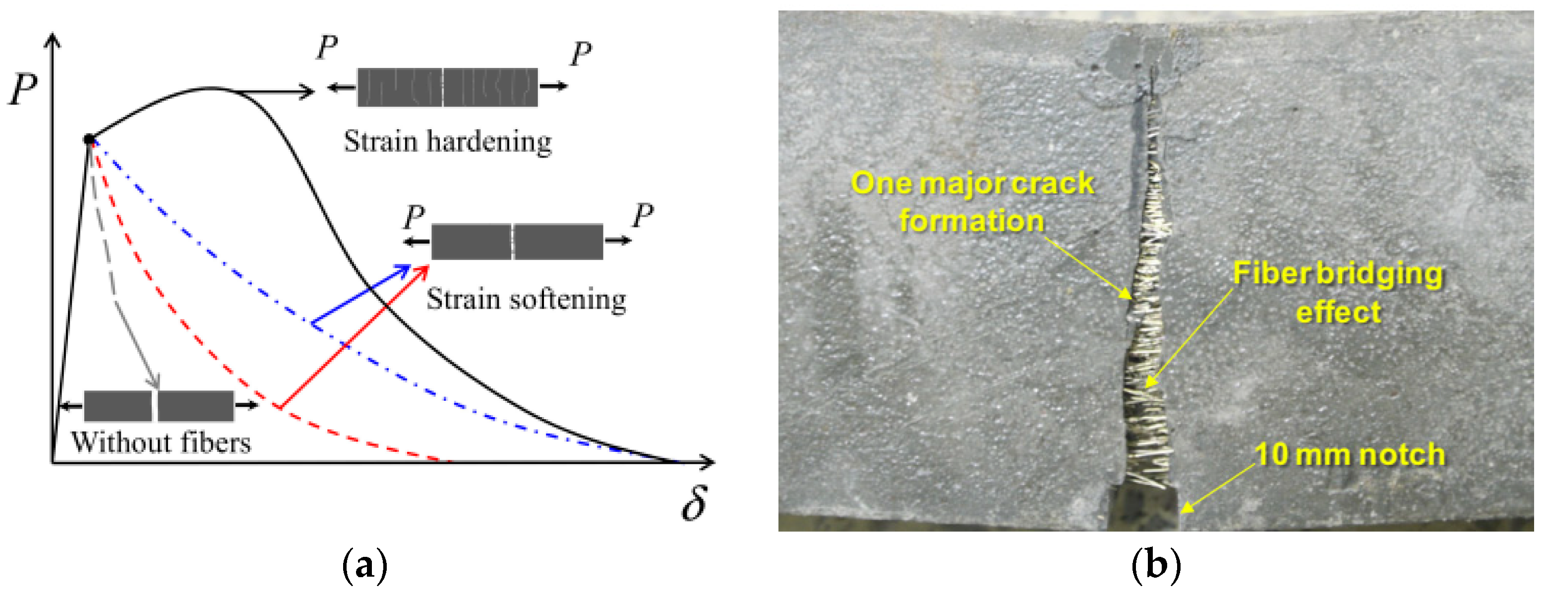
Figure 1. (a) Softening and hardening behavior of UHPC in uniaxial tension [8]; (b) Bridging effect of steel fibers [9].
Buildings 15 03335 g001
Figure 2. Cumulative particle size distribution of UHPC constituents.
Buildings 15 03335 g002
Figure 3. Steel fibers: (a) Straight micro; (b) Hooked-end macro.
Buildings 15 03335 g003
Figure 4. Details of I-beams.
Buildings 15 03335 g004
Figure 5. Production of test specimens: (a) Cube and cylinder specimens; (b) Prismatic beams; (c) I-beams.
Buildings 15 03335 g005
Figure 6. Test setups for compression and tensile tests: (a) Axial compression; (b) Splitting tensile.
Buildings 15 03335 g006
Figure 7. Fracture test setup for prismatic beam specimens.
Buildings 15 03335 g007
Figure 8. Flexural test setup and instrumentation for I-beam specimens.
Buildings 15 03335 g008
Figure 9. Effect of fiber volume fraction and hybrid fiber use: (a) Compressive strength; (b) Splitting tensile strength.
Buildings 15 03335 g009
Figure 10. Effect of fiber content on load vs. CMOD response: (a) Control; (b) Mono1.0; (c) Hybrid1.0; (d) Mono2.0; (e) Hybrid2.0.
Buildings 15 03335 g010
Figure 11. Details of CMOD determination in fracture tests using 2D-DIC: (a) CMOD measurement with GOM Correlate; (b) Comparation of experimental and analytical results.
Buildings 15 03335 g011
Figure 12. Crack evaluation of the UHPC prismatic beams at different stages: (a) Mono1.0; (b) Hybrid1.0; (c) Mono2.0; (d) Hybrid2.0.
Buildings 15 03335 g012
Figure 13. Failure modes of the I-beams: (a) Control; (b) Mono1.0; (c) Hybrid1.0; (d) Mono2.0; (e) Hybrid2.0.
Buildings 15 03335 g013
Figure 14. Details of 2D-DIC analysis for I-beams: (a) Calibration of 2D-DIC; (b) Determination of crack widths with GOM Correlate.
Buildings 15 03335 g014
Figure 15. Propagation of shear cracks: (a) Peak load; (b) Ultimate load.
Buildings 15 03335 g015
Figure 16. Sher crack evolution of I-beams: (a) Control; (b) Mono1.0; (c) Hybrid1.0.
Buildings 15 03335 g016
Figure 17. Crack evaluation of I-beams failed in flexure: (a) Cracking patterns at peak load; (b) Crack width evaluation.
Buildings 15 03335 g017
Figure 18. Load vs. midspan deflection curves of the I-beams: (a) Control; (b) Mono1.0; (c) Hybrid1.0; (d) Mono2.0; (e) Hybrid2.0.
Buildings 15 03335 g018
Figure 19. Load vs. rebar strain curves of I-beams: (a) Control; (b) Mono1.0; (c) Hybrid1.0; (d) Mono2.0; (e) Hybrid2.0.
Buildings 15 03335 g019
Table 1. Quantities of the materials for UHPC mixtures in kg/m3.
MixtureControlMono1.0Mono2.0Hybrid1.0Hybrid2.0
Cement700700700700700
Silica fume170170170170170
Blast furnace slag300300300300300
Quartz sand103010059801005980
Water200200200200200
Superplasticizer1717171717
Steel fiber-78
(Micro)
156
(Micro)
39 + 39
(Micro + Macro)
78 + 78
(Micro + Macro)
Table 2. Chemical composition and physical properties of the binder materials.
MaterialsCementSilica
Fume
Blast Furnace Slag
SiO2 (%)19.8095.9041.49
Al2O3 (%)5.470.4716.34
Fe2O3 (%)3.460.080.61
CaO (%)64.440.6629.26
MgO (%)1.300.487.68
SO3 (%)2.670.071.90
Na2O (%)0.400.540.80
K2O (%)0.670.8211.10
Loss on ignition (%)-0.53-
Density (kg/m3)325022002900
Specific surface area (m2/kg)38020,000–30,000-
Table 3. Properties of steel fibers.
TypeLength
(mm)
Diameter
(mm)
Aspect RatioTensile Strength
(MPa)
Straight micro 130.16812500
Hooked-end macro 300.55551345
Table 4. Summary of fracture test results.
ControlMono1.0Hybrid1.0Mono2.0Hybrid2.0
fLOP (MPa)6.656.376.427.295.79
CMOD (mm)0.010.020.020.020.01
fR,1 (MPa)-17.2417.7223.8520.43
CMOD (mm)-0.500.500.500.50
fR,2 (MPa)-18.1716.6925.6619.89
CMOD (mm)-1.501.501.501.50
fR,3 (MPa)-17.2114.3624.4417.66
CMOD (mm)-2.502.502.502.50
fR,4 (MPa)-15.1912.4621.4515.77
CMOD (mm)-3.503.503.503.50
fR,max (MPa)6.6518.2018.1025.8121.08
CMOD (mm)0.011.250.821.300.78
Table 5. Summary of results for I-beams.
ControlMono1.0Hybrid1.0Mono2.0Hybrid2.0
Pcr,flex (kN)4.3511.4310.0732.2411.61
Δcr,flex (mm)0.150.350.270.840.42
Pcr,shear (kN)41.9256.2946.91--
Δcr,shear (mm)1.662.011.49--
Py (kN)---234.21231.10
Δy (mm)---5.516.00
Pp (kN)68.55186.98136.57273.33264.56
Δp (mm)2.887.655.437.247.61
Pu (kN)68.55147.29108.40215.67214.81
Δu (mm)2.888.286.8041.8234.05
Notes: Δcr,flex: midspan deflection at flexural cracking, Pcr,flex: flexural cracking load, Δcr,shear: midspan deflection at shear crakcin, Pcr,shear: shear cracking load, Py: yield load, Δy: midspan deflection at yield load, Δp: midspan deflection at peak load, Pp: peak load, Δu: midspan deflection at ultimate load, Pu: ultimate load.
Disclaimer/Publisher’s Note: The statements, opinions and data contained in all publications are solely those of the individual author(s) and contributor(s) and not of MDPI and/or the editor(s). MDPI and/or the editor(s) disclaim responsibility for any injury to people or property resulting from any ideas, methods, instructions or products referred to in the content.