1. Introduction
Concrete plays a pivotal role in modern urban development and infrastructure, with its usage continuously growing. This growth is accompanied by extensive consumption of natural sand, gravel, and cement, exacerbating resource depletion and environmental impacts [
1,
2]. To mitigate these impacts, the use of industrial by-products to produce green concrete has become a major research focus. Coal gangue, a major solid waste generated during coal mining and processing, accounts for about 10–20% of China’s annual coal output. If left piled up, it can cause severe ecological and environmental pollution [
3,
4,
5]. Currently, the most economical and common way to utilize coal gangue is to crush and grade it as coarse aggregate for making coal-gangue concrete, which is then applied in mining-area infrastructure and underground support structures [
6,
7]. However, because coal-gangue aggregate is intrinsically weak and highly porous, the resulting gangue aggregate concrete (GAC) typically shows lower compressive strength and stiffness and greater brittleness than ordinary concrete [
8,
9,
10]. These deficiencies frequently prevent GAC from satisfying the rigorous load-bearing requirements of critical structural members.
To address the poor mechanical performance of GAC, some researchers have enclosed GAC in steel tubes to provide external confinement, thereby improving both strength and ductility [
11,
12,
13]. However, steel tubes themselves are prone to local buckling under axial load, which can compromise the safety of support structures [
14]. Although thicker steel walls can postpone buckling, they significantly increase self-weight and material costs. Moreover, steel corrodes rapidly in the humid, chemically aggressive environment of underground mines, leading to the progressive loss of capacity and serviceability [
15]. Consequently, the long-term durability of steel-confined GAC remains problematic. Compared with steel, fiber-reinforced polymers (FRP) are attractive due to their low density, high specific strength and stiffness, and excellent corrosion resistance [
16,
17,
18]. In composite systems, fabric-reinforced cementitious matrix (FRCM) jackets—high-strength FRP embedded in an inorganic mortar—retain the lightweight and corrosion-resistant attributes of FRP while offering improved fire performance [
19]. In parallel, FRP jackets have gained widespread acceptance for retrofitting conventional reinforced-concrete members [
16,
17,
18]. Researchers have recently proposed replacing steel tubes with FRP shells to produce concrete-filled FRP tube (CFFT) columns, which demonstrate superior confinement efficiency and corrosion durability [
20,
21]. Given these advantages, FRP confinement could provide the performance boost needed to transform GAC into a structurally reliable, environmentally sustainable construction material.
Extensive studies have demonstrated that confinement with FRP markedly enhances the ultimate strength and ductility of concrete columns, thereby mitigating brittle failure [
22]. Ren et al. applied FRP jackets to low-strength coal-gangue concrete and introduced a new FRP-confined coal-gangue column, testing cylinders (200 mm diameter × 450 mm height) without internal steel reinforcement. The reported GFRP-confined compressive strengths were about 47.6 MPa for coal-gangue concrete and 122 MPa for natural aggregate concrete. Their tests revealed substantial gains in axial load capacity and deformability, with ductility improving most in the weakest mixes [
23]. FRP confinement has also proved successful in specialized settings. In island reef regions where freshwater and natural aggregates are scarce, researchers have developed seawater coral-aggregate concrete (SCAC) and replaced traditional steel cages with glass-fiber-reinforced-polymer (GFRP) tubes. In their tests on circular CFFT (300 mm diameter × 800 mm height), the columns had measured 28-day cube strengths of approximately 94.14 MPa. The resulting columns combined high load-bearing capacity with ample ductility, while completely avoiding steel-corrosion problems [
24]. These examples highlight a core advantage: the corrosion resistance of FRP allows it to deliver effective external reinforcement for concrete made with marginal aggregates.
Although FRP-confined ordinary concretes and various special-aggregate concretes have been widely investigated, high-volume fly-ash coal-gangue self-compacting concrete (CGSC) remains virtually unstudied. CGSC contains two industrial by-products. Fly ash partially replaces cement, cutting clinker consumption and improving flow, whereas crushed coal gangue substitutes natural coarse aggregate, turning mine waste into a resource. Yet this “double-waste” blend displays mechanical drawbacks. Gangue aggregates are weak and highly porous, reducing the composite’s strength and elastic modulus. Excessive fly ash, meanwhile, limits cement hydration, creating a more porous matrix and further depressing strength [
25]. External confinement with FRP tubes, therefore, appears essential for restoring CGSC’s mechanical performance, but the effect of high fly-ash content on the axial strength and ductility of gangue concrete under FRP confinement is still unclear. Moreover, because the FRP jacket hides the interior, crack initiation and propagation cannot be observed directly, complicating failure analysis [
26]. Acoustic-emission (AE) monitoring offers a solution. It records elastic waves emitted as cracks form and grow, enabling real-time tracking of damage evolution [
27,
28,
29,
30,
31]. Prior work shows that AE event rate, energy, and frequency content can segment compression into distinct stages, identify crack types, and even provide failure warnings. Therefore, incorporating AE technology into the experimental study of GFRP-confined CGSC can offer quantitative characterization of the damage evolution in this new composite material.
Against this backdrop, this paper presents an experimental study on the axial compressive behavior of GFRP tube-confined CGSC. Monotonic compression tests were coupled with real-time AE monitoring to analyze the effects of GFRP tube confinement on the load-bearing capacity and deformation performance of such concrete columns, as well as the development and evolution of internal cracks during failure. This novel combination of AE sensing with mechanical testing provided quantitative evidence of the damage progression inside the confined concrete, allowing verification of the material’s unique failure characteristics. The findings will help to achieve a further understanding of the strengthening mechanism provided by GFRP confinement for self-compacting concrete with high waste content, and will provide a reference for the design and application of this new type of green concrete column in engineering practice.
3. Self-Compacting Concrete Performance Tests
3.1. Workability
This experiment also conducted slump flow and T500 flow time tests according to the Technical Specification for Application of Self-Compacting Concrete [
34] to ensure that both the NSC and CGSC meet the requirements for self-compactability. The test results of self-compacting concrete workability are presented below, listing the fresh mix performance results for different mix proportions (
Table 4).
The NSC-80 had an average slump flow of about 601 mm (grade SF1) and a T500 time of 6.0 s, exhibiting good flowability and cohesiveness (viscosity grade VS1). In contrast, the CGSC-80 showed a slump flow around 568 mm (a reduction of about 5%), and a longer T500 time of 7.6 s. This indicates that the introduction of coal-gangue coarse aggregate slightly reduced the filling ability and flow rate of the SCC. On one hand, coal-gangue aggregate likely has higher water absorption and porosity, reducing the effective free water in the mix. On the other hand, the irregular shape and rough surface of coal-gangue particles increase flow resistance. These factors together lead to a lower slump flow and increased flow viscosity for CGSC-80. Nevertheless, the slump flow of CGSC-80 remained above 550 mm, satisfying the workability requirement for SCC (SF1 grade), and its T500 time stayed within the VS1 range. This means that by adjusting the admixture dosage, this mix still achieved acceptable self-leveling capability.
As the fly-ash content increased, the workability of CGSC improved markedly. For CGSC-85, the slump flow rose to about 625 mm, and the T500 time dropped to 5.6 s, indicating a significantly faster flow compared to CGSC-80. With an even higher fly-ash content of 90% (CGSC-90), the average slump flow reached 670 mm, and some samples achieved up to 710 mm (entering SF2 grade, slump flow > 650 mm). Meanwhile, the T500 time decreased to 4.4 s, still within the VS1 viscosity grade. This demonstrates that a high fly-ash content greatly enhances the flowability of the coal-gangue concrete mixture. The incorporation of a large amount of fine fly-ash particles provides a lubricating effect and fills the voids between aggregates, allowing the paste to flow more easily. Notably, within the range of fly-ash replacement ratios tested (80–90%), no obvious segregation of the concrete was observed. This indicates that even at high fly-ash replacement levels, coal-gangue SCC can still achieve good workability.
3.2. Compressive Mechanical Performance
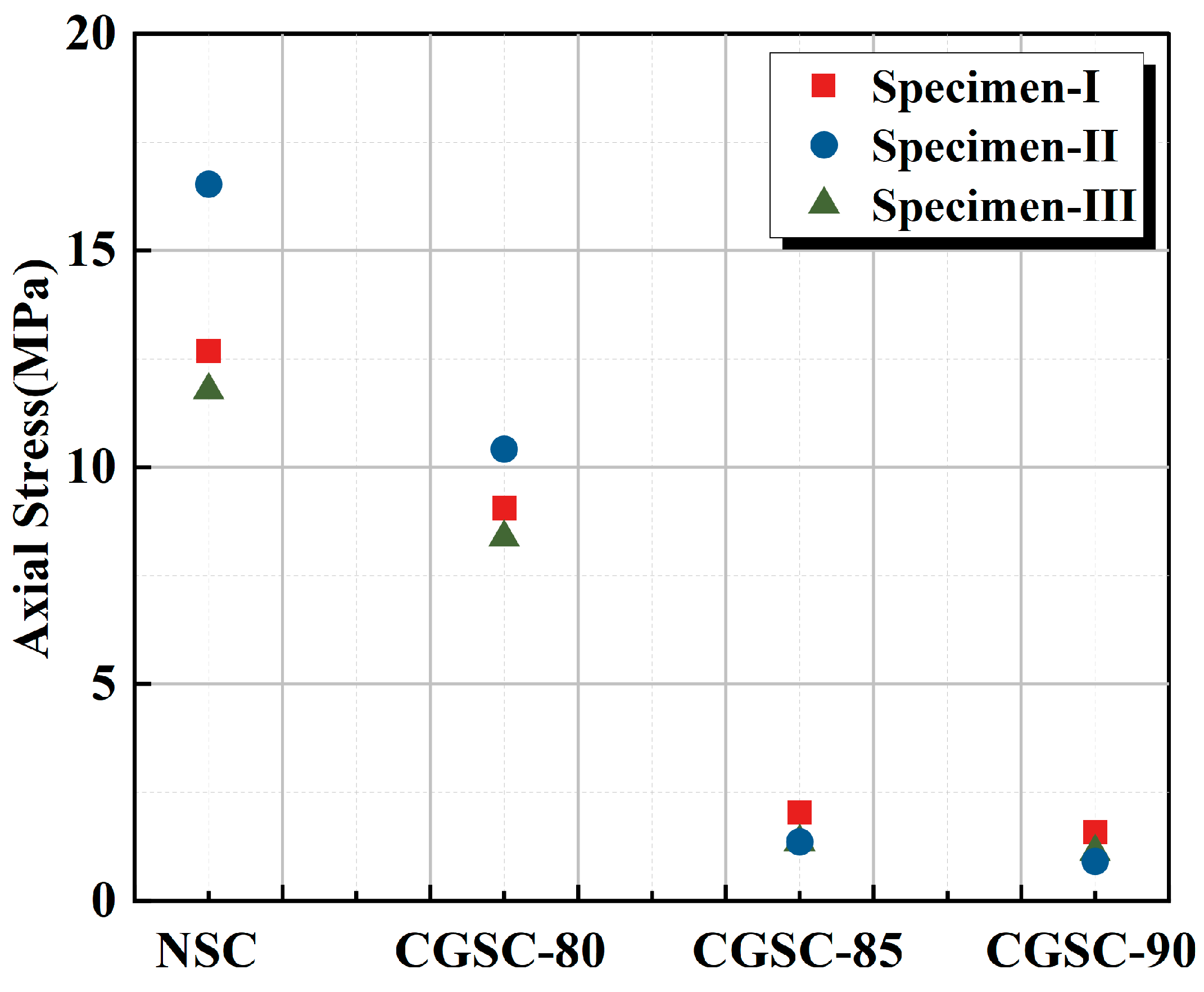
The 28-day compressive strengths of the unconfined concrete core with different aggregates and fly-ash content are shown in
Figure 7. NSC-80 averaged 13.66 MPa, whereas CGSC-80 reached 9.29 MPa—about 68% of NSC-80 (a 32% reduction). The primary reason for this strength loss is the inherently low strength of the coal-gangue aggregate. Coal gangue is a solid waste byproduct of coal mining (also referred to as coal rejects), characterized by a loose, porous structure and the presence of weak components. When used as aggregate, it often becomes the limiting weakness of the concrete’s strength. On the one hand, during loading, the coal-gangue particles themselves can fracture and crumble, absorbing some strain energy but no longer contributing to load bearing. On the other hand, the interfacial transition zone between the coal gangue and the cement paste is of poor quality—the interface bond strength and shear strength are lower than with natural aggregate. Therefore, it is more prone to interface debonding and crack propagation under stress [
23].
Fly-ash content is another important factor affecting the matrix strength. Because an extremely high fly-ash replacement was used (reducing the cement content), the overall strength level of the specimens is low. As the fly-ash content increases from 80% to 90% (i.e., cement content dropping from 20% to 10%), the unconfined compressive strength of the coal-gangue concrete plummeted from 9.29 MPa to 1.21 MPa, a reduction of as much as 87%. This decline indicates that at, ultra-high fly-ash levels, the cement available for hydration is severely insufficient. The production of hydration products drops sharply, the paste structure becomes porous and loose, destroying the load-bearing skeleton, and ultimately, the strength of the cementitious matrix is drastically weakened.
The low strength of the coal-gangue aggregate and the defects in its interfacial transition zone, combined with the lack of hydration products at ultra-high fly-ash content, together result in a weak load-bearing skeleton in the concrete matrix, causing the unconfined compressive strength to be significantly lower than that of the natural aggregate system. Particularly for the CGSC-90 specimens, the dual adverse effect of “weak aggregate and weak matrix” reduced the compressive strength to only 1.21 MPa, far below the safety threshold for engineering applications. To make up for this strength shortfall and to suppress early brittle failure, the introduction of external GFRP confinement becomes imperative.
4. Experimental Results and Discussion
4.1. Experimental Observation
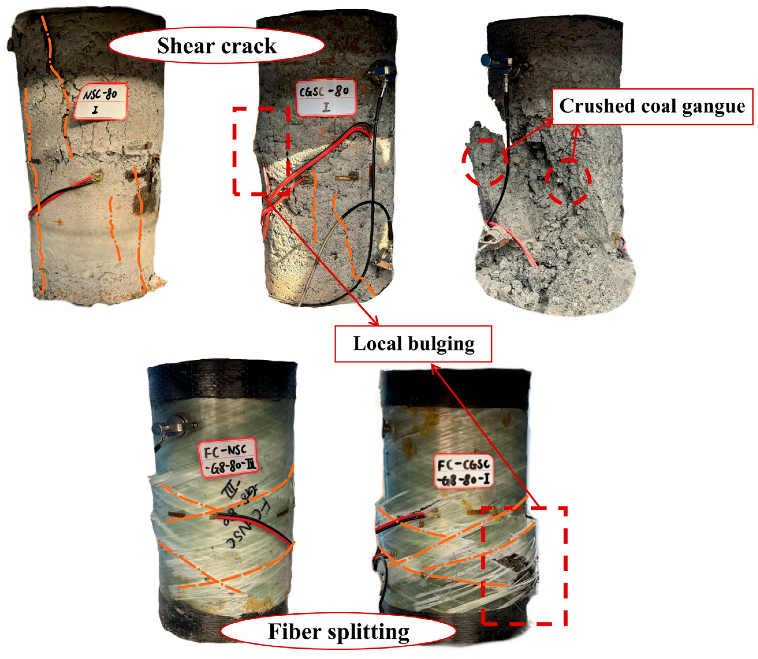
As shown in
Figure 8, observation of the specimen failure modes reveals that under unconfined conditions, the incorporation of a high proportion of fly ash (and the corresponding reduction in cement) leads to a loose cementitious matrix. Consequently, both the NSC and CGSC exhibited obvious longitudinal through-going cracks. The NSC specimens mainly displayed a typical brittle splitting failure: cracks propagated along the loading direction, forming distinct shear failure planes, and failure occurred mostly around the aggregate–mortar interfaces. In contrast, the CGSC specimens, due to the lower strength of the coal-gangue aggregate itself, showed a different failure pattern. During loading to failure, aside from pronounced debonding at the aggregate–mortar interfaces, a large number of the coal-gangue aggregates were themselves crushed, creating new separation surfaces between the aggregates and the paste and causing aggregate particles to detach from the matrix. This failure mode is not exactly the same as the common shear failure observed in ordinary aggregate concrete, causing the CGSC specimens to exhibit even more severe brittle failure characteristics, with the post-peak load-bearing capacity dropping off rapidly.
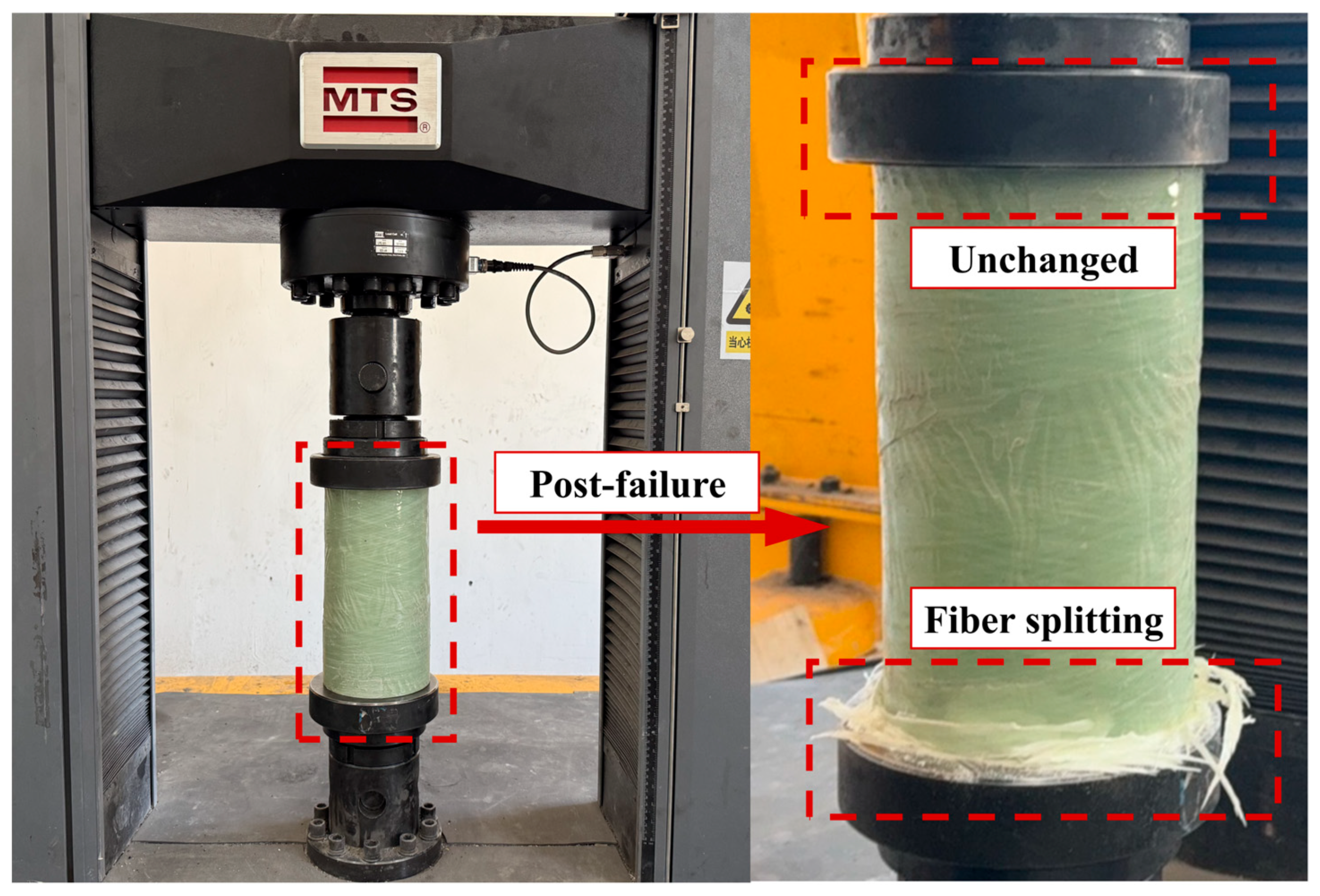
Under GFRP tube confinement, the specimens’ failure was dominated by hoop rupture of the GFRP tube. All five groups of the GFRP-confined specimens ultimately showed fractures of the GFRP jacket along the hoop (circumferential fiber) direction, accompanied by a loud snapping sound, indicating a typical sudden brittle rupture. The cracking direction of the GFRP tube was aligned with the fiber winding angle, and a small amount of longitudinal tearing along the fiber direction was also observed. However, there were slight differences in the failure modes between the GFRP-confined specimens with different coarse aggregates. As detailed in
Figure 8, although the early internal cracking and interface debonding in the CGSC specimens were suppressed by the GFRP confinement, they often caused overly concentrated strain in certain local regions of the GFRP tube at the moment of failure, resulting in distinct localized bulging tears. In contrast, the NSC specimens, having a relatively more uniform internal structure, typically exhibited a more uniform hoop cracking pattern in the GFRP jacket without premature local failure.
4.2. Axial Load-Axial Strain Behavior
4.2.1. General Behavior
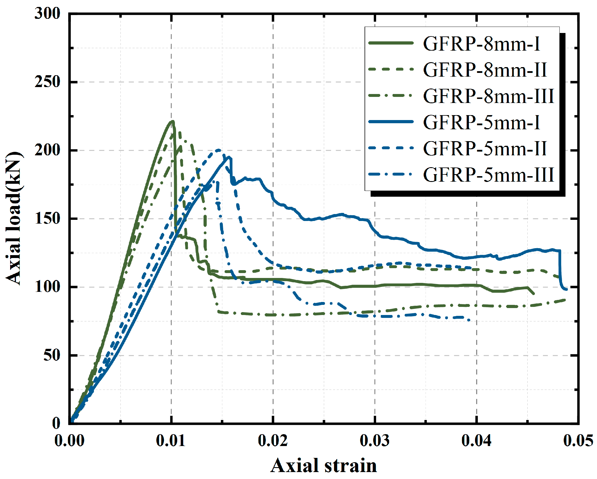
As presented in
Table 5, all groups satisfy the validity checks prescribed by the GB/T50081-2019 [
35], and the dispersion (SD and COV) is generally at a good level, indicating stable and reliable data. The test results demonstrate that GFRP confinement can significantly enhance the axial compressive load capacity and ductility of the concrete core, with an especially pronounced effect on the low-strength CGSC. For example, the peak strength of unconfined NSC-80 was about 13.66 MPa, which increased to 78.06 MPa under confinement with an 8 mm GFRP tube—an increase of approximately 470%. The unconfined CGSC-80 had a peak strength of only 9.29 MPa. Wrapping it with a 5 mm thick GFRP tube boosted the strength to 58.5 MPa (about 509% higher), while an 8 mm GFRP tube raised it further to 74.52 MPa, an increase of over 660%. The lateral confinement provided by the GFRP tube greatly increased the load-bearing capacity, and the percentage increase became larger as the initial strength of the core concrete decreased—a weaker matrix yields a higher relative strength gain under confinement. Under the 8 mm GFRP confinement, the peak strength of the CGSC specimens nearly matched that of the NSC specimens. It clearly demonstrates that with a sufficiently thick GFRP jacket, the strength gap between different aggregate concretes can be greatly narrowed. In other words, when lateral confinement is sufficient, the initial strength of the core concrete is no longer the sole controlling factor. The external FRP jacket likewise becomes a governing factor in the member’s load capacity.
4.2.2. Effect of Aggregate Type
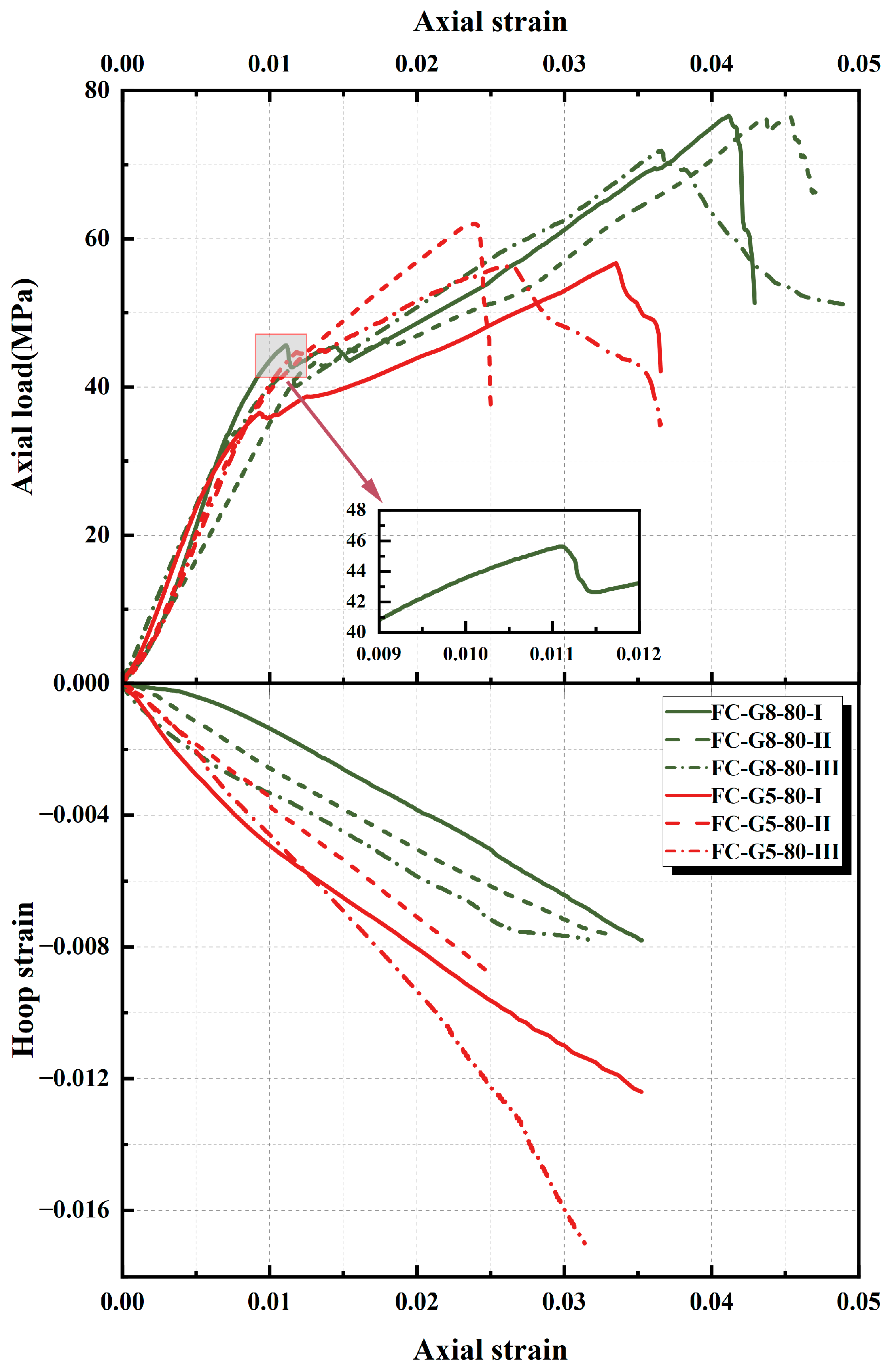
Stress–strain curves for FC-NSC-G8-80 and FC-CGSC-G8-80 under identical GFRP confinement are plotted in
Figure 9 for direct comparison. In terms of peak strength, the two groups’ values are almost identical (as noted above, 78.06 MPa vs. 74.52 MPa), indicating that sufficient lateral confinement has, to an extent, bridged the inherent strength difference between the two types of aggregate.
Both FC-NSC-G8-80 and FC-CGSC-G8-80 show a typical bilinear response: the initial segment is approximately linear elastic. Then the curve shows a turning point where the slope decreases significantly, entering a second stage characterized by continued stress increase with gradually reducing stiffness, which is consistent with the known behavior of FRP-confined concrete [
24]. The overall shapes of the curves for the ordinary aggregate and coal-gangue aggregate concretes are similar, but there are differences in the details around the turning point. After reaching the turning point, the NSC specimen’s curve continued to rise smoothly without an evident stress drop, whereas the CGSC specimen showed a small sudden stress-drop plateau at the turning point, after which the stress began to rise again under the GFRP confinement. Based on the observed failure modes, it can be inferred that in GFRP-confined CGSC, the internal aggregate and mortar rapidly develop cracks and undergo compaction at the onset of fracture, causing the stress–strain curve to briefly level off. Subsequently, the GFRP provides confining pressure that allows the stress to resume increasing. Despite this, ultimately, both specimens failed by GFRP rupture, with the curve dropping abruptly. This confirms that, under GFRP confinement, the stress–strain response reflects the combined action of the concrete core and the FRP jacket rather than the core alone. The FRP jacket delays the stress drop and provides a second phase of load-bearing, causing the curve to exhibit a long, gradual ascent until FRP failure. Wang et al. [
24] reported a similar trend in coral-aggregate concrete: the porous, low-strength aggregate caused compaction before confinement fully engaged, leading to a slight drop in the stress–strain curve in the transition zone [
24].
4.2.3. Effect of GFRP Tube Thickness
The wall thickness of the GFRP tube directly determines the confinement stiffness, which is a critical factor influencing compressive performance. In
Figure 10, the curves for FC-CGSC-G5-80 and FC-CGSC-G8-80 highlight the effect of increasing tube thickness from 5 mm to 8 mm.
Both groups exhibit a bilinear response, but the thick-walled GFRP provides a significantly higher peak strength and axial strain capacity. Specifically, the peak stress of the FC-CGSC-G8-80 specimens (74.52 MPa) is about 27% higher than that of the FC-CGSC-G5-80 specimens (58.5 MPa), and the corresponding peak axial strain increases from 0.028 to 0.041—a ductility improvement of nearly 50%. The thick-walled GFRP tube, owing to its greater tensile strength and stiffness, can provide higher lateral confinement pressure, delaying the radial deformation of the core concrete and thereby markedly enhancing the load capacity and ductility. In contrast, the thin-walled GFRP has a limited confinement capability. Once the concrete reaches its own strength, the rapid lateral expansion causes the thin jacket to fail prematurely, preventing full development of the second-stage load-bearing potential. Therefore, the stress–strain curve of the FC-CGSC-G5-80 specimens drops off more quickly after the turn, ending sooner. The FC-CGSC-G8-80 specimens exhibit a longer, more gradually ascending post-turn segment, indicating a higher strain capacity and energy-absorption ability. Overall, as the GFRP tube thickness increases, the effectiveness of the GFRP confinement in improving strength and ductility is greatly enhanced.
4.2.4. Effect of Fly-Ash Content
The fly-ash content alters the initial strength and brittleness of the core concrete, thereby affecting its behavior under GFRP confinement.
Figure 11 shows stress–strain curves for CGSC confined by the same 8 mm GFRP tube but with different fly-ash contents. As fly ash increases from 80% to 85% to 90%, peak strength decreases: FC-CGSC-G8-80, -85, and -90 average 74.52, 53.99, and 42.63 MPa, respectively. High fly-ash content leads to an extremely low core concrete strength, so even with GFRP confinement, the peak strength still drops substantially (a 43% decrease when increasing fly ash from 80% to 90%). However, compared to the drastic 87% drop in the unconfined case, the GFRP confinement significantly compensates for the strength loss. Notably, for the weakest mix FC-CGSC-G8-90, whose unconfined strength is only 1.21 MPa, the peak stress under confinement still reached 42.63 MPa—roughly equivalent to the level of a normal C30 concrete. This suggests that external confinement has, to an extent, given a rebirth to the ultra-low-strength concrete.
In terms of the shape of the stress–strain curves, increasing the fly-ash content makes the slope of the second stage more gradual. The curve of FC-CGSC-G8-80 remains relatively steep after the inflection point, whereas the curves of the specimens with 85% and 90% fly ash become more gently rising in the post-turn segment. This indicates that for very low-strength matrices, GFRP confinement primarily restrains lateral dilation and builds load gradually. The latter part of the curve becomes flatter and longer rather than steep. Meanwhile, irrespective of fly-ash content, all these curves exhibit a brief stress drop plateau around the turning point, reflecting that the high-fly-ash concrete core undergoes a certain degree of volumetric compaction and rapid crack development upon initial cracking.
In summary, increasing the fly-ash content (thereby lowering the core concrete strength) causes the peak strength under GFRP confinement to decrease, and the second stage of the stress–strain curve to become longer and more gently sloped. Furthermore, from the stress–strain curves, it can be observed that when the concrete strength is extremely low, the activation of the GFRP confinement is noticeably delayed. Only when the concrete has undergone larger deformations—approaching compaction and beginning to exhibit lateral expansion—does the GFRP gradually engage to provide confinement, which then leads to a significant increase in load capacity.
4.3. Axial-Hoop Strain Behaviour
To clarify deformation coordination under GFRP confinement, this study further analyzes the relationship between axial and hoop strains. As demonstrated by
Figure 9,
Figure 10 and
Figure 11, the axial-hoop strain curves of each group of specimens exhibit an approximately linear-growth trend overall. In other words, the Poisson effect of concrete under GFRP confinement behaves roughly as a constant ratio, and the differences between groups in their axial-hoop strain response are mainly reflected in the slope of the curves.
The FC-NSC-G8-80 specimens showed a significantly faster increase in hoop strain compared to the FC-CGSC-G8-80 specimens—for the same axial strain, the NSC had a larger hoop strain. A steeper slope indicates more pronounced lateral expansion, suggesting that NSC undergoes a higher proportion of lateral deformation when compressed. In the CGSC, however, the internal aggregate is more easily crushed and compacted, so part of the axial deformation is absorbed by the collapse of internal voids rather than translating into overall lateral expansion. Hence, the axial-hoop strain slope is relatively smaller. Thus, a considerable portion of axial deformation in CGSC does not produce corresponding hoop expansion but is absorbed by internal collapse, yielding an apparent Poisson’s ratio lower than that of ordinary aggregate concrete.
Meanwhile, the axial-hoop strain curve of the FC-CGSC-G5-80 specimens has a steeper slope than that of the FC-CGSC-G8-80 specimens. Due to its lower lateral stiffness, the thin-walled GFRP tube allows greater hoop strain for a given axial compression, resulting in a steeper slope. This indicates that the thin-walled confinement is insufficient—the axial deformation is not fully restrained, and more of it converts into lateral expansion. Increasing tube thickness to 8 mm provides stronger confinement and markedly slows lateral deformation. Consequently, the slope of the axial-hoop strain curve is reduced.
Under a fixed confinement thickness (8 mm), as the fly-ash content increases from 80% to 85% to 90%, the curve slope gradually decreases. This means that for the same axial strain, the hoop strain growth in the high fly-ash specimens is slower, i.e., the lateral expansion is more effectively suppressed. It can be considered that the high fly-ash content greatly reduces the strength and stiffness of the concrete core. The specimen undergoes internal crack closure and local crushing early in compression, so part of the axial deformation does not convert into overall hoop expansion. For weaker cores, external confinement more effectively controls lateral deformation, manifested by the fact that each increment of axial strain produces an even smaller increment of hoop strain.
4.4. Distribution of Hoop Strains
Aside from the overall development of hoop strain, the spatial uniformity of lateral deformation in different specimens is also of interest. The hoop-strain distributions—illustrated as radar plots for representative specimens—appear in
Figure 12. The four axes of each radar chart correspond to four strain gauges evenly arranged around the specimen’s circumference, while the shape of the plot reflects the synchronicity and uniformity of lateral deformation in different orientations.
The results show that the lateral expansion of the NSC under thick-walled GFRP confinement was relatively uniform. For FC-NSC-G8-80, hoop strains in all four directions were similar and the radar plot was nearly circular, indicating coordinated, uniform deformation under GFRP confinement. This corresponds with its observed failure mode: the FC-NSC-G8-80 specimen ultimately showed even, uniform cracking of the GFRP tube, with no sign of localized premature failure. In contrast, the specimens in the FC-CGSC-G5-80 and FC-CGSC-G8-80 groups showed a clearly non-uniform distribution of hoop strain. Before reaching peak load, the degree of lateral expansion differed significantly between different sides, and the radar plot appears as an ellipse with one end protruding. For the FC-CGSC-G8-85 and FC-CGSC-G8-90 groups, the radar plots evolved further into an ellipse with protrusions at two opposite ends.
The non-uniform distribution of hoop strain directly reflects uncoordinated deformation inside the material. In specimens incorporating coal-gangue aggregate with a high fly-ash content, the aggregate’s low strength, irregular morphology, and weak interfacial bonding prevent the constituent phases from deforming synchronously under compression. As a result, local weak zones exhibit pronounced lateral expansion before the surrounding material. Once the local confinement ruptures, the lateral restraint at that point collapses, causing stress to concentrate rapidly in the adjacent concrete core and precipitating global instability and failure of the entire specimen. A direct manifestation of this localized failure mode is the uneven distribution of hoop strain around the cross-section. Although GFRP confinement raises capacity, non-uniform deformation persists and intensifies at high strains.
5. Acoustic Emission Analysis
5.1. Cumulative AE Hit Count and Hit Rate
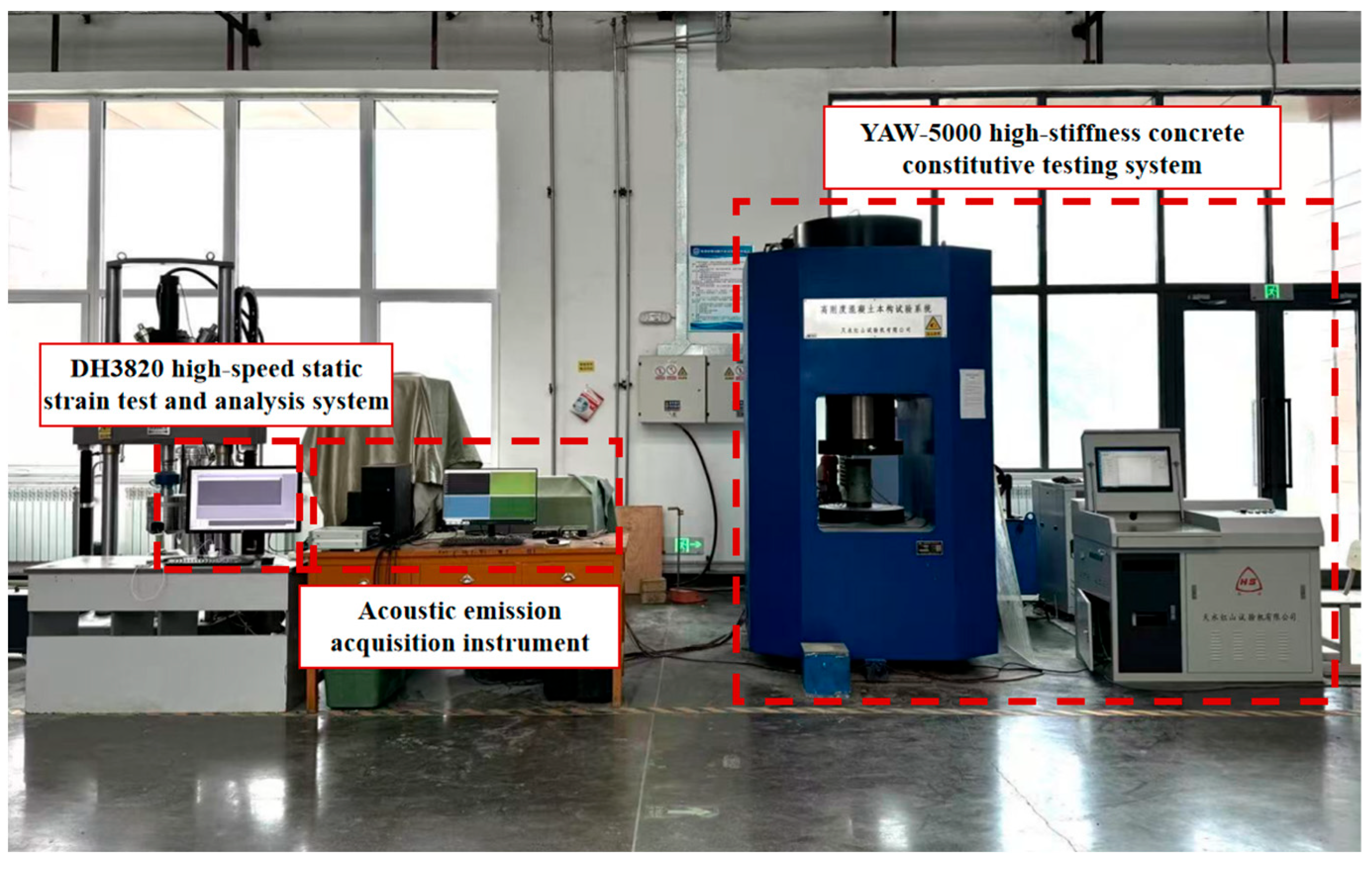
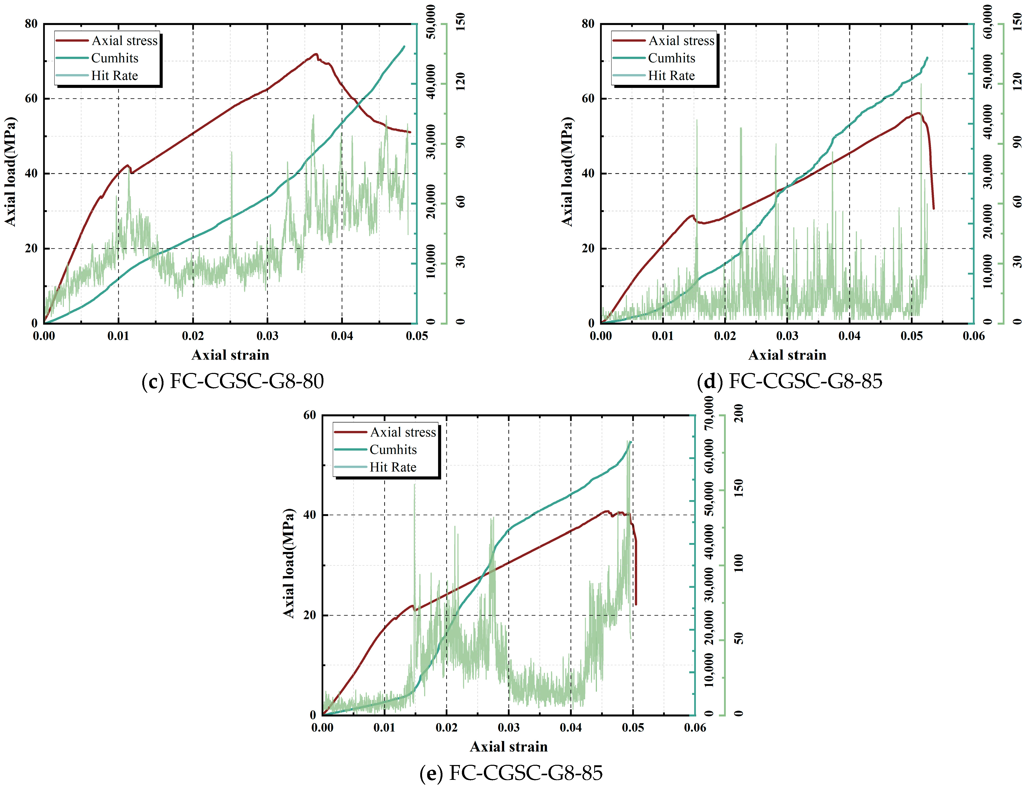
Acoustic-emission (AE) monitoring during axial compression provides real-time information on internal damage evolution. The experimental results show that the cumulative AE hit count of GFRP-confined specimens over time exhibits distinct stage-wise characteristics (
Figure 13). The AE hit-rate curve shows a double-peak pattern consistent with a three-stage damage process: an initial compaction stage (first peak), a stage of stable crack growth, and an ultimate failure stage (second peak).
It is noteworthy that for the GFRP-confined CGSC, the stress drop plateau at the inflection point of the stress–strain curve is clearly accompanied by an abrupt spike in the AE hit rate. This is because a large number of microcracks rapidly propagate inside the specimen at that moment, causing a sudden increase in AE events. The observation confirms that the short plateau marks rapid damage development and the onset of effective GFRP confinement. Subsequently, due to the confinement provided by the GFRP, the specimen’s load-bearing capacity is restored, and it enters the mid-to-late phase of stable crack propagation. Finally, as the stress approaches its peak, macroscopic cracks rapidly coalesce and the structure enters the unstable failure stage. Correspondingly, the AE hit rate rises sharply again to form a second prominent peak, reflecting the sudden emergence of numerous through-going cracks and the rupture of the GFRP tube.
From a quantitative perspective, there are obvious differences in the intensity of AE activity and the cumulative hit count among the specimen groups. In FC-NSC-G8-80, the early AE peak is modest and the hit rate remains low until just before peak stress, indicating greater resistance to microcrack initiation. In contrast, for the CGSC specimens, due to the low strength of the aggregate and the presence of many inherent flaws, relatively frequent AE events occur already in the initial loading stage. The first hit rate peak appears earlier and is higher in magnitude, indicating that early microcrack initiation is much more active. Meanwhile, the AE hit rate of the FC-CGSC-G8-80 specimens is significantly lower than that of the FC-CGSC-G5-80 specimens, indicating that with a thicker GFRP tube confinement, damage accumulation is slower. As for the fly-ash content, the CGSC with a higher fly-ash content has poorer matrix strength and interfacial properties, making microcracks easier to form at early loading stages, which leads to a faster and denser accumulation of AE events.
Throughout the loading process, the cumulative hit count can be used to quantify the extent of damage evolution. Specimens with more initial defects or more rapid damage development show a faster increase and a higher peak in cumulative AE hits. Conversely, denser and more intact structures exhibit fewer cumulative AE events. This indicates that damage indices based on the cumulative hit count can effectively characterize the damage level of concrete at different stress levels. Therefore, by comparing the AE hit rate curves and cumulative hit counts of different specimens, one can identify differences in internal crack propagation rates and failure modes, providing a basis for understanding the failure mechanisms under axial compression.
5.2. b-Value
The acoustic emission b-value is an important parameter that describes the distribution characteristics of AE event amplitudes. It derives from the Gutenberg–Richter law in seismology, where the exponent b links event amplitude to occurrence frequency on a log-linear scale [
36]. Physically, it reflects the proportion of large-amplitude events relative to small-amplitude events in the current damage state: a higher b-value indicates that small-energy, small-crack events dominate (i.e., the internal damage is mainly in the form of dispersed microcracks), whereas a lower b-value indicates the occurrence of more high-energy AE events, implying the formation of larger-scale cracks. Because the b-value is sensitive to crack-size distribution, a sustained decrease is widely taken as a warning of imminent macroscopic failure [
37]. In this experiment, the dynamic b-value was calculated by analyzing changes in the distribution of AE amplitudes, in order to examine differences in crack development characteristics among the different specimens throughout the loading process.
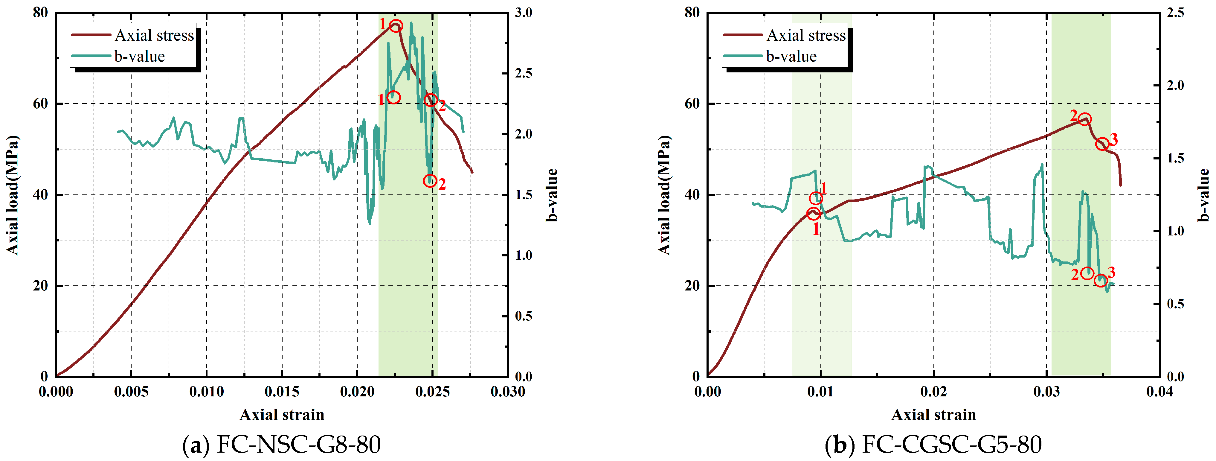
As evidenced by
Figure 14, the b-value of each specimen group generally exhibits a trend of gradual decline followed by a sharp drop as loading progresses. The circled regions denote characteristic points where the stress and the corresponding b-value exhibit pronounced changes. In the initial elastic compaction stage, AE events are mainly of low amplitude and low energy, and the b-value usually remains at a high level with little fluctuation, indicating that only a small number of microcracks are present and their scale is limited. As stress approaches crack initiation, medium-amplitude events appear and the b-value declines, marking microcrack extension and the onset of stable propagation. Notably, for the stress drop plateau observed in the GFRP-confined CGSC, the dynamic b-value often exhibits significant fluctuations or abrupt jumps—this corresponds to the occurrence of larger crack events during the aforementioned plateau stage. It can be considered that the sudden cracks associated with this plateau represent the transition of internal microcracks into macrocracks. Beyond the plateau, during the middle-to-late segment of stable crack propagation, the b-value declines steadily, reflecting both the progressive growth of internal cracks and the increasing prevalence of large-amplitude AE events. However, during this period, the b-value may show some fluctuations: when crack growth is relatively mild over a certain interval, the b-value may rebound slightly or remain steady. Whereas when a sudden localized failure occurs (for example, when a crack suddenly propagates through), the b-value correspondingly exhibits a downward spike. These fluctuations reflect the stepwise and non-uniform nature of crack propagation. Finally, in the unstable failure stage, the b-value drops sharply. This is because, as the peak load is approached, a series of high-energy AE events occur (e.g., GFRP fibers rupturing and concrete cracking violently). The contribution of low-energy events becomes negligible, causing the b-value to plummet to a very low level. A sudden drop in b-value serves as a warning of imminent failure.
In general, specimens with a denser internal structure and stronger confinement maintain a higher b-value in the early-to-middle loading stages and exhibit a more gradual decline. Conversely, specimens with more initial defects or weaker confinement have a lower b-value from the early loading stage, which drops sooner and more rapidly. For specimens made with coal-gangue aggregate, high fly-ash content, or confined by thinner GFRP tubes, the concrete core and interface contain more defects, and the confinement effect is insufficient. Consequently, high-amplitude AE events appear earlier in the amplitude spectrum—meaning that local macrocracks form at relatively lower stress levels, causing the b-value to begin decreasing earlier. Later, the b-value often plunges further, indicating unstable failure with rapid formation and coalescence of multiple large cracks.
6. Discussion
6.1. Factor Contributions and Significance
To quantify the relative importance of the experimental variables, a one-way analysis of variance (ANOVA) was performed separately for the peak axial strength () and the peak axial strain (). The fixed parameters examined included aggregate type (natural gravel and coal gangue), GFRP tube thickness (5 mm and 8 mm), and fly-ash content (80%, 85%, and 90%). Due to limitations in residual degrees of freedom, only the main effects were considered, excluding interactions. The significance level was set at α = 0.05, and the residual mean square was used as the error term.
The ANOVA results (
Table 6) indicated that the main effect of aggregate type on peak axial strength is not significant (
p > 0.05), whereas its effect on peak axial strain is significant (
p < 0.001, accounting for 49% of the variance). This is consistent with the observed axial-hoop strain interaction. CGSC tends to undergo crushing and densification under compression, so part of the axial deformation is dissipated internally rather than immediately converted into global lateral dilation, leading to a higher peak strain while the strength gain remains limited.
GFRP tube thickness had a significant positive effect on both peak metrics, accounting for 18% of the variance in peak axial strength and 24% in peak axial strain (p < 0.001). A thicker GFRP tube provides greater confinement stiffness, more effectively delaying the radial dilation of the core concrete and postponing instability, thereby resulting in a higher peak load and improved deformation capacity.
Fly-ash content is the dominant factor governing peak axial strength (p < 0.001, accounting for 75% of the variance), and the strength decreases obviously as the replacement ratio increases. By contrast, the main effect of fly-ash content on peak axial strain is not significant (p > 0.05). This further confirms the pronounced weakening effect of excessive fly-ash replacement on strength. High replacement levels weaken the matrix and the interfacial bond, reduce the efficiency of FRP-core coupling, and delay the effective activation of confinement.
Overall, peak axial strength is governed primarily by fly-ash content, with GFRP thickness as a secondary factor, whereas peak axial strain is governed mainly by aggregate type and GFRP thickness.
6.2. Practical Implications and Design Recommendations
Grounded in the preceding experiments and multi-factor ANOVA, the proposed system—GFRP tube-confined CGSC—emerges as a technically viable solution for underground support. It enhances mechanical performance while also improving deformation capacity.
In practice, the installation of GFRP tube-confined CGSC follows the similar workflow as cast-in-place bored piling. Prefabricated GFRP tubes are manufactured off-site to the specified dimensions, transported to the site, and installed in the borehole or excavation as stay-in-place formwork. Concrete is then cast inside, eliminating formwork stripping. Because the tube encloses the fresh concrete, it also serves as a curing jacket that conserves moisture and heat, reduces early-age moisture loss, and promotes internal curing [
38]. The method is particularly straightforward for circular sections, which provide uniform hoop confinement. By contrast, confinement in rectangular sections is non-uniform: the flat sides offer limited lateral restraint and effective confinement concentrates near rounded corners [
39]. Studies show that, all else being equal, circular FRP-confined columns develop higher capacities than non-circular members. Fabricating non-circular GFRP tubes is also more challenging, and corners tend to be weak points. Hence, under current technological and economic conditions, GFRP tube confinement is best suited to circular or near-circular members, and designs should prioritize such locations to capitalize on confinement efficiency and constructability.
For the design of concrete-filled GFRP tube supports, the tube wall thickness should match the required capacity and ductility. For concretes with low-strength or porous aggregates (e.g., coal-gangue or coral aggregate concrete), a sufficiently thick GFRP tube should be prioritized to ensure effective confinement and compensate for a weaker core. Increasing wall thickness is also the most effective means of improving performance where high load or large deformation demands are expected. When using fly ash as a partial cement replacement, its adverse impact on compressive strength must be weighed. If necessary, one can reduce the replacement level or blend silica fume and/or ground-granulated blast-furnace slag to recover matrix strength and enable a higher confined capacity. Regarding structure dimensions, sizing should follow the relevant codes and project requirements. This study focused on short columns with a height-to-diameter ratio of 2:1. Future work will investigate the performance of full-scale elements recognizing potential size effects.
In underground engineering, this system offers distinct advantages in several scenarios. It can be used for deep foundations and drilled shafts, where GFRP tube-confined concrete piles have been implemented in bridge and building foundations as an alternative to conventional reinforced-concrete piles [
40]. In tunnels and underground drifts, GFRP tube-confined concrete can serve as arch supports or lining elements. Traditional steel sets are corrosion-prone and have limited deformability, whereas concrete-filled GFRP tubes markedly improve corrosion resistance and overall ductility. In environments with aggressive groundwater or surrounding media, the GFRP tube is non-corrodible and limits the ingress of water and ions, offering a durability advantage over conventional reinforced concrete [
41]. Given the favorable deformation capacity of GFRP-confined concrete, the system is also suitable for seismic regions and impact-resistant applications. With continued research and field practice, GFRP tube composite members are likely to become a green and efficient option for underground support and foundations, especially in harsh environments.

