Article

Effects of Near-Fault Vertical Ground Motion on Seismic Response and Damage in High-Speed Railway Isolated Track–Bridge Systems

1
School of Civil Engineering, Tianjin Chengjian University, Tianjin 300384, China
2
Tianjin Key Laboratory of Civil Building Structure Protection and Reinforcement, Tianjin Chengjian University, Tianjin 300384, China
3
School of Civil Engineering, National Engineering Research Center of High-Speed Railway Construction Technology, Central South University, Changsha 410075, China
*
Author to whom correspondence should be addressed.
Buildings 2025, 15(18), 3320; https://doi.org/10.3390/buildings15183320
Submission received: 18 August 2025 / Revised: 7 September 2025 / Accepted: 12 September 2025 / Published: 14 September 2025
(This article belongs to the Special Issue Dynamic Response Analysis of Structures Under Wind and Seismic Loads)

Abstract

China’s high-speed railway (HSR) network relies heavily on bridge structures to ensure track regularity, with many lines crossing seismically active near-fault zones. Near-fault ground motions are characterized by significant vertical components (VGMs), which challenge conventional seismic design practices. Although seismic isolation techniques are widely adopted, the effects of VGMs on the dynamic response and damage mechanisms of HSR track–bridge systems remain insufficiently studied. To address this gap, this study develops a refined finite element model (FEM) in OpenSEES that integrates CRTS II slab ballastless tracks, bridge structures, and friction pendulum bearing (FPB). Using nonlinear time-history analyses, the research systematically investigates structural responses and damage degrees under different ratios of vertical-to-horizontal peak ground acceleration (αVH) and multiple seismic intensity levels (frequent, design, and rare earthquakes). Key findings reveal that αVH values in near-fault regions frequently range between 0.5 and 1.5, often exceeding current design code specifications. The impact of VGMs intensifies with seismic intensity: negligible under frequent earthquakes but significantly amplifying damage to piers, bearings, and track interlayer components (e.g., sliding layers and CA mortar layers) during design and rare earthquakes. While seismic isolation effectively mitigates structural responses through energy dissipation by bearings, it may increase sliding layer displacements and lead to bearing failure under rare earthquakes. Based on these insights, tiered αVH values are recommended for seismic design: 0.65 for frequent, 0.9 for design, and 1.2 for rare earthquakes. These findings provide critical references for the seismic design of HSR infrastructure in near-fault regions.

1. Introduction

As critical national transportation infrastructure in China, high-speed railways (HSR) feature a remarkably high proportion of bridges within the domestic network to ensure track levelness [1,2]. With HSR lines extending into regions traversing active fault zones, the track–bridge systems of HSR in near-fault seismic belts face significant seismic challenges. Relevant research indicates that near-fault ground motions exhibit distinct characteristics, including a pronounced long-period velocity pulse and intense vertical ground motion (VGM) [3,4,5], which result in structural responses distinctly different from those induced by far-field ground motions [6,7] and cause particularly severe damage to engineering structures [8,9,10,11]. Although seismic isolation techniques have proven effective in mitigating seismic damage to buildings and highway bridges [12,13,14], existing research predominantly focuses on horizontal seismic responses, with insufficient attention paid to the significant vertical ground motions in near-fault regions. Increased seismic observation records reveal that the peak vertical ground accelerations in some strong motions exceed their horizontal counterparts, constituting a major contributor to structural damage [15]. Consequently, investigating the response patterns and damage mechanisms of seismically isolated HSR track–bridge systems subjected to near-fault vertical ground motions holds important theoretical value and engineering guidance significance.
Domestic and international scholars have conducted extensive research on the characteristics of near-fault ground motions. Studies demonstrate that pulse effects significantly influence structural responses [16,17] and can amplify the displacements of seismic isolation bearings [18,19]. Jiang et al. [20], for instance, found that fling-step pulses induce more pronounced responses in HSR track–bridge systems. Concurrently, the VGM component’s impact is also notable. Guo et al. [21] demonstrated that the VGM in near-fault regions plays a crucial role and can potentially cause running trains to derail from bridge tracks. Ryan et al. [22] demonstrated that considering the vertical seismic component leads to significant amplification of base shear in structures isolated with spherical sliding bearings. Shao et al. [23] proposed a novel model of bridge seismic fragility surfaces conditioned on the horizontal peak ground velocity and the ratio of vertical to horizontal ground motion, and analyzed the influence and mechanism of VGM on damage probability. Wei et al. [24] further corroborated that VGMs can affect the seismic fragility of bridge structures. However, these studies have primarily explored the effects of near-fault seismic pulse and vertical characteristics on structural systems, while comparatively less attention has been paid to the seismic response and damage extent of isolated bridge systems under such conditions.
Seismic isolation bearings and damping devices are both effective in dissipating seismic energy for vibration control, among which isolation bearings are widely recognized as critical components for reducing seismic force transmission [25]. Compared with ductile bridges, the vulnerable location in isolated bridges shifts from piers to the bearings themselves, and under near-fault ground motions, bearing failure has become one of the primary damage modes [26]. In recent years, hybrid damping systems [27,28,29] and advanced isolation designs for high-speed railway (HSR) bridges [30,31] have been continuously developed and applied. Among various isolation devices, friction pendulum bearings (FPB) are widely used in bridge structures due to their advantages of simple design, large deformation, easily adjustable period, and excellent seismic isolation performance [32,33,34]. Therefore, it is essential to conduct in-depth research on the mechanical behavior of friction pendulum bearings under vertical ground motions (VGM). Loghman et al.’s study shows that considering the vertical component of earthquakes has no significant effect on determining the peak bearing displacement, and the maximum average error reaches 29.5% when calculating the base shear of the structure while ignoring this component [35]. Through statistical analysis, Zhong et al. [36] found that the VGM component should be reasonably considered in evaluating the seismic performance of friction-isolated bridges in near-fault regions, which is particularly critical for accurately calculating the response of friction pendulum bearings. Xiao et al. [37] examined the influence of FPB isolation parameters on component damage and operational safety performance within the HSR track–bridge system subjected to near-fault earthquakes. Despite these valuable efforts, significant limitations persist: existing research—including fragility assessments under VGM [23,24]—has not yet systematically clarified the response and damage mechanisms of key components in HSR seismically isolated bridge systems subjected to near-fault VGMs, nor has it fully revealed the behavioral laws and damage evolution paths of the track–bridge–isolation bearing coupled system under varying VGM intensity indices (αVH). Thus, targeted research is urgently needed to address these gaps.
Consequently, to address these limitations, this study develops a refined integrated track–bridge–isolation bearing FEM, analyzes αVH-seismic intensity coupling effects, quantifies damage in key components under varying VGM intensities, evaluates isolation performance, and proposes αVH recommendations. The specific research contents are as follows: Section 2 develops and validates a refined FEM incorporating the track structure, bridge, and seismic isolation bearings. Section 3 performs nonlinear time-history analysis to compare the structural displacements under isolated and common working conditions, considering different ratios of αVH of vertical peak ground acceleration (PGAV) to horizontal peak ground acceleration (PGAH) (where αVH = PGAV/PGAH), as well as different earthquake intensities. Section 4, based on a defined damage index system, quantifies the damage degree and progression patterns of critical components under different αVH ratios and seismic intensities, evaluates the seismic control effect of the isolation technology, and puts forward suggestions for the selection of αVH values. Section 5 draws together the research findings and conclusions, providing a scientific basis for the seismic design of HSR infrastructure in near-fault regions.

2. The Structural Dynamic Analysis Model

2.1. Simulation of HSR Track–Bridge System

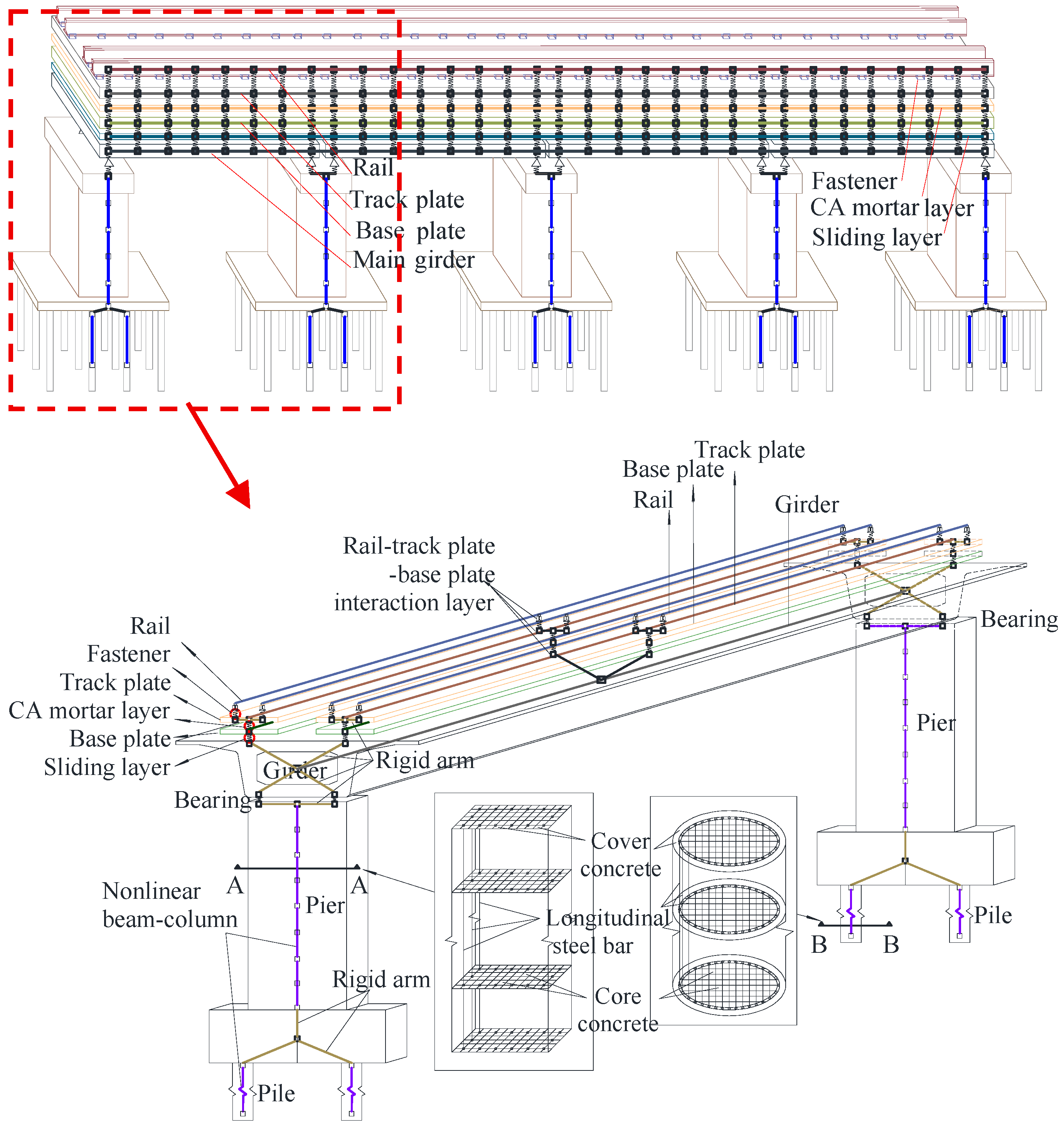
In this study, a typical high-speed railway simply supported beam bridge located in a near-fault area with an 8-degree seismic fortification intensity on a Type II site is taken as the analysis object. The bridge structure comprises four equal spans of 32 m each, as shown in Figure 1. The main girders of the bridge are equal-section single-box single-chamber box girders, and the piers are solid piers with rectangular sections, all with a height of 13.5 m. The track system employs a typical CRTS II slab ballastless track system as shown in Figure 1, whose material selection, dimensional parameters, and component layout are consistent with those of existing studies [32,33].
A dynamic analysis model of the HSR track–bridge system is established in this study utilizing the OpenSEES platform, as shown in Figure 2. Based on the bearing types employed in the HSR track–bridge system, the system is divided into two categories: the common system and the isolated system. The dynamic calculation models of these two systems are identical in all aspects except for the simulation method used for the bearings.
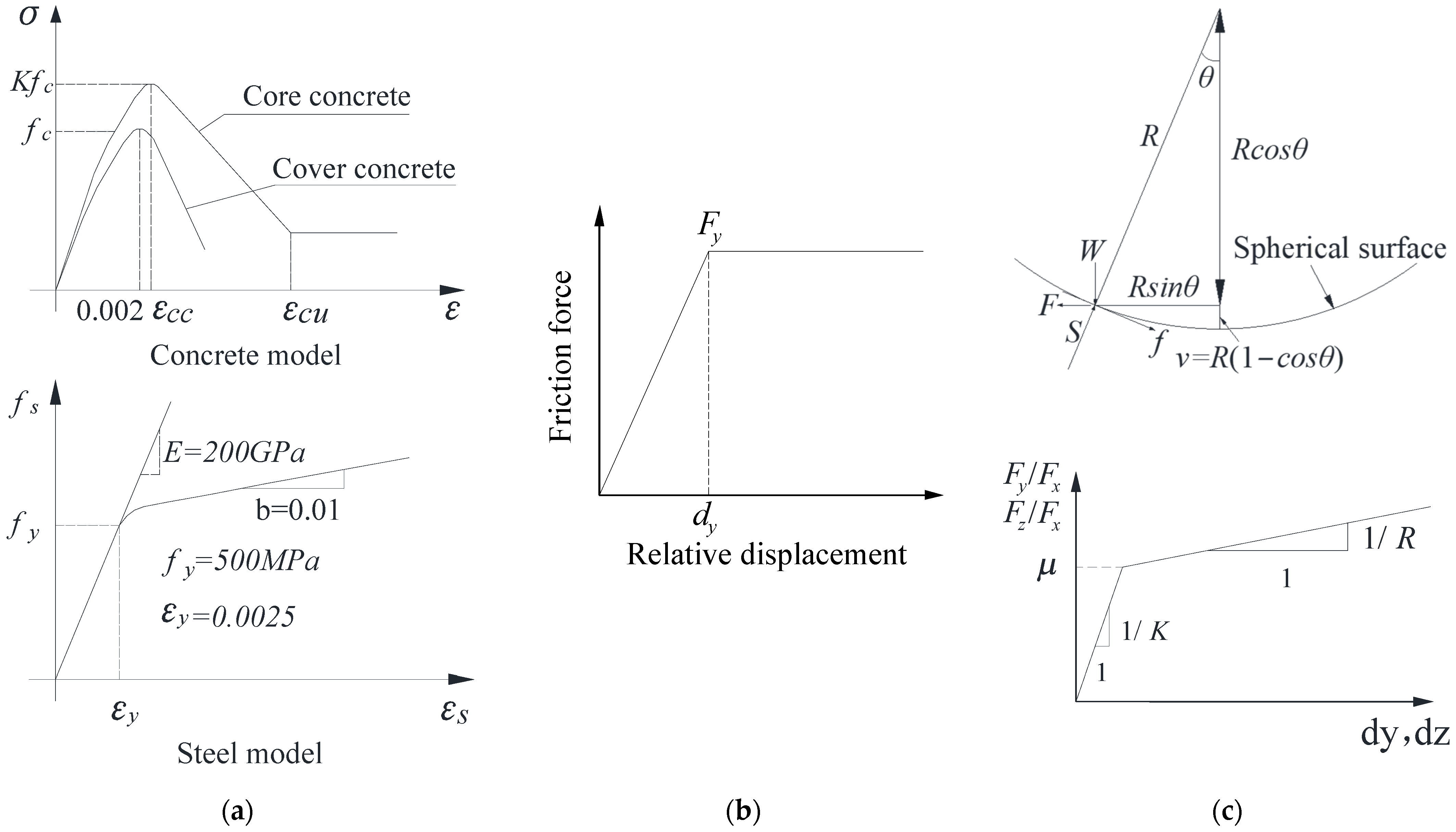
Specifically, the modeling approaches are maintained identically for the main girders, piers, and track system components in the two models. Based on evidence from existing seismic damage investigations [38], the rail, track plate, base plate, and girders are generally observed to remain elastic under seismic excitation. Consequently, these components are simulated using elastic beam elements in this study, with their corresponding parameters provided in Table 1. However, it is worth noting that under extreme near-fault earthquakes, these components may yield, altering system force distribution and energy dissipation, and causing localized damage (e.g., rail buckling, girder residual displacements) that affects bridge safety. Thus, this study’s findings rely on these members’ elasticity; future research should investigate their nonlinearity and failure modes to fully assess system response under broader extreme loads. Piers are simulated using fiber elements in OpenSEES to analyze their nonlinear behavior under seismic action [37]. The cover concrete and core concrete are represented by the Concrete 01 material model, with distinct parameter sets to account for their different mechanical behaviors. This model was selected due to its well-validated Kent–Scott–Park-based compressive response, computational robustness during dynamic analysis, and alignment with common seismic assessment practices that accept neglecting tensile behavior for piers. The ultimate compressive strength of the core concrete is calculated according to the Kent–Scott–Park model, explicitly incorporating the confinement effect provided by the reinforcement. Longitudinal reinforcement is modeled using the Steel 02 material in OpenSEES, with specific parameters shown in Figure 3a. The interlayer components of the CRTS II slab ballastless track are all simulated using zero-length elements. The force–displacement relationships for these nonlinear zero-length elements are presented in Figure 3b, and their corresponding parameters are tabulated in Table 2. These parameters were carefully calibrated: the values for the fixed and sliding bearings were selected in accordance with the Chinese seismic design code for highway bridges (JTG/T B02-01-2008) [39], while the parameters for the sliding layer, CA layer, and fasteners were directly derived from pushing test data to ensure simulation accuracy [24]. Furthermore, the vertical constitutive behavior of the aforementioned components is modeled by employing large stiffness values.
The distinction between the two systems is manifested primarily in the simulation of the bearings. Spherical steel bearings are employed in the common system. For the isolated system, friction pendulum bearings (FPBs) are selected and modeled using the SingleFPB element in OpenSEES. This dedicated element adopts a geometrically nonlinear Coulomb friction constitutive model to simulate the FPBs’ hysteretic behavior. The damping of FPBs is primarily provided by frictional dissipation, consistent with the Coulomb friction mechanism inherent to the element. The specific parameters for this element are presented in Figure 3c. The design parameters include the friction coefficient and the radius of curvature of the sliding surface, which are assigned values of 0.02 and 3.5 m, respectively. Specifically, these key parameters were determined based on conventional design practices [40]: the isolation period typically ranges from 2.5 to 4 s, and the curvature radius—calculated from the isolation period—is set to 3.5 m, a common value within the 2–4 m range. The friction coefficient, chosen as 0.02, accounts for sliding velocity, seismic hazard, and temperature, corresponding to a medium-hard soil site under its seismic fortification intensity.

2.2. Verification of Finite Element Model

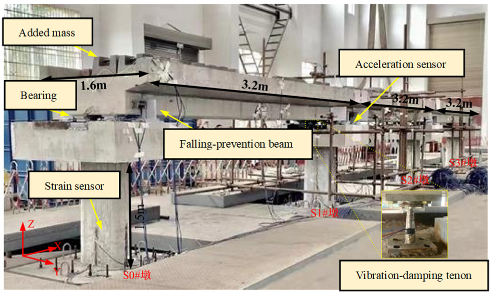
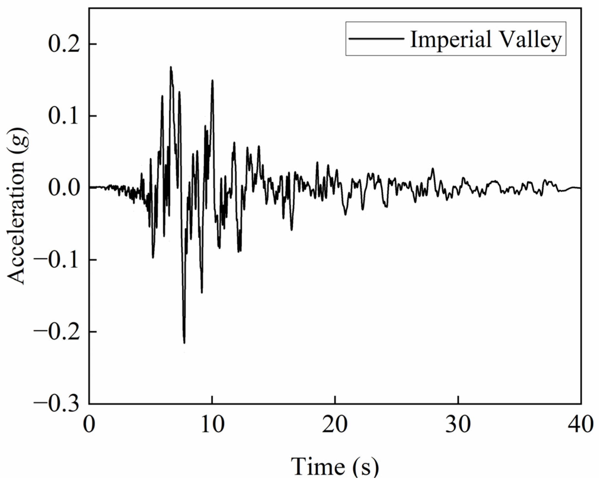
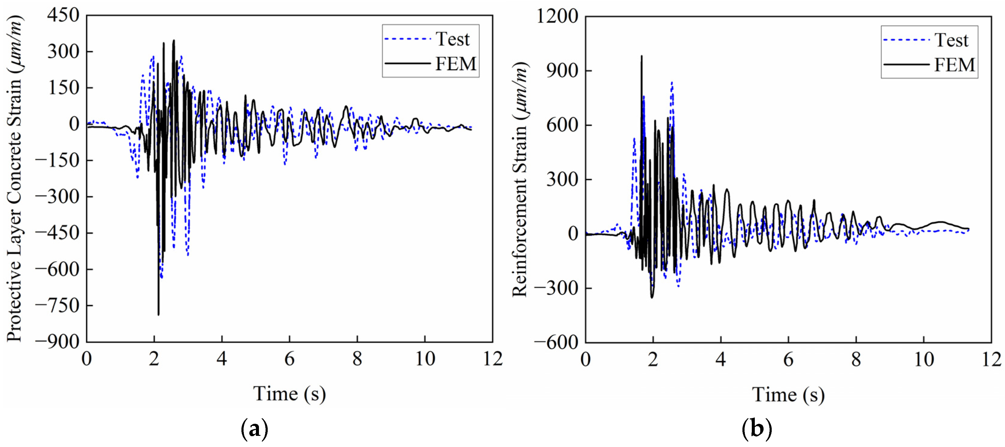
To validate the reliability of the finite element method adopted in this study, an FEM of the prototype bridge used in the shaking table test was developed using the approach in Section 2.1. The numerical results were compared with shaking table test data from Hu et al. [41]. The test model, shown in Figure 4, was a 1:10 scaled four-pier three-span simply-supported railway bridge with 1.5 m piers. The similarity ratios between the test model and the prototype were as follows: 1:10 (length), 1:1 (material), and 1.25:1 (acceleration) [41]. Validation was performed under the Imperial Valley wave (RSN170, PGA = 0.235 g) excitation; its acceleration time history is shown in Figure 5. The comparison results of the concrete cover and steel reinforcement strains in the longitudinal direction are shown in Figure 6 and Table 3. The results indicate that the finite element simulation agrees well with the shaking table test measurements. The relative errors between the numerically simulated peak values of the FEM responses for the HSR simply-supported bridge and the test-measured peaks fall within an acceptable range, demonstrating that the finite element modeling method used in this study exhibits high accuracy and reliability.

2.3. Near-Fault Ground Motions and Distribution of αVH

A total of 100 near-fault ground motion records were selected from the PEER ground motion database, with selection criteria designed to ensure representativeness for high-speed railway bridges under near-fault seismic conditions. All records are from shallow crustal earthquakes in active tectonic zones, characterized by rupture distances ranging from 0.07 km to 28.04 km and moment magnitudes between 5.4 and 7.9. To match the Type II site condition of the bridge prototype, all selected records were strictly limited to PEER Site Class C (VS30 between 360 m/s and 760 m/s).
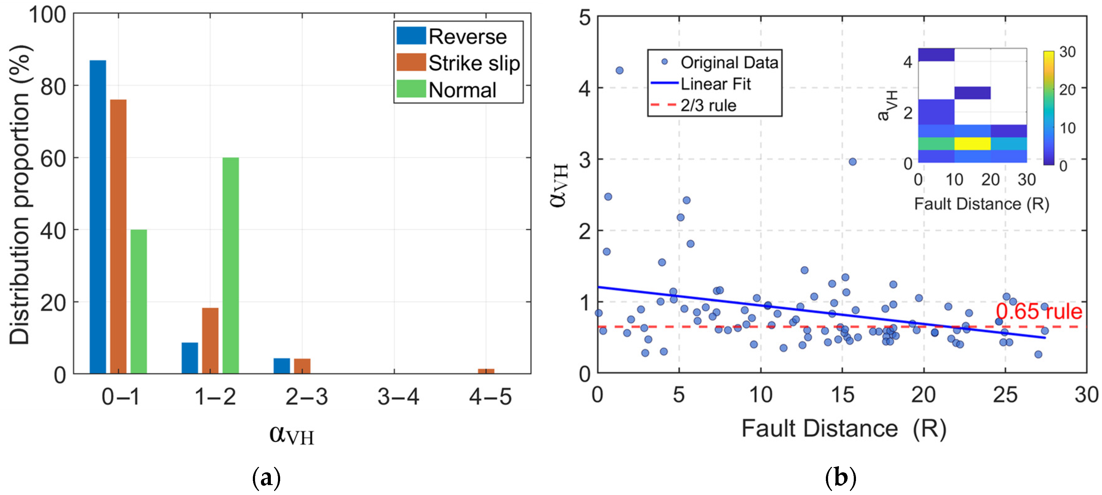
To preserve the inherent characteristics of real earthquakes and maintain the natural variability of the vertical-to-horizontal acceleration ratio, the original records were used without any scaling procedure or exclusion of pulse-type motions at this stage. This approach ensures that αVH remains an intrinsic property of each ground motion record and avoids introducing artificial bias into the statistical analysis of its distribution. To investigate the response of the HSR track–bridge system under various combinations of vertical and horizontal seismic excitations, the ratio of the peak vertical ground acceleration (PGAV) to the peak horizontal ground acceleration (PGAH), denoted herein as αVH and assumed to be an independent variable, is employed to quantify VGMs [23,24]. Systematic statistical analyses were performed on these 100 near-fault ground motion records to establish the distribution relationships between the αVH values and the rupture distance, moment magnitude, and faulting mechanism, as illustrated in Figure 7.
The distribution proportions of αVH in each interval (0–1, 1–2, 2–3, 3–4, 4–5) under three fault mechanisms (reverse, strike-slip faults, and normal) of near-fault earthquakes are presented in the bar chart in Figure 7a. The specific distribution characteristics are as follows: Under reverse faults, αVH accounts for the highest proportion (over 85%) in the 0–1 interval, then drops significantly to within 10% in the 1–2 interval, and remains at an extremely low level (<5%) in the 2–3 and higher intervals. For strike-slip faults, αVH makes up nearly 75% in the 0–1 interval, decreases to approximately 20% in the 1–2 interval, and negligible proportions (<5%) are maintained in higher intervals (≥2–3). In normal fault regimes, αVH occupies about 40% in the 0–1 interval, rises to around 60% in the 1–2 interval to become dominant, and maintains an extremely low proportion in the 2–3 and higher intervals. Collectively, distinct mechanistic partitioning of αVH distributions across fault mechanisms is conclusively demonstrated.
Figure 7b shows the distribution and density of the original αVH data with varying fault distances. It can be observed that the original αVH data generally exhibit a decreasing trend with the increase in fault distance, as quantitatively confirmed by the blue linear fitting line. Significant deviations are observed between actual αVH scatter points and the normative reference (“0.65 rule”, red dashed line), with most data points positioned above this benchmark. The data density histogram in the upper right corner (with a color scale of 0–30, where values are positively correlated with density) objectively reveals the spatial distribution characteristics of αVH values with fault distances. Within the fault distance range of 10–20 km, αVH values exhibit significant spatial aggregation, mainly densely distributed in the interval of 0.5–1.5. The practice of uniformly setting αVH to 0.65 in current codes may lead to a systematic underestimation of the vertical ground motions, which in turn causes negative deviations in the prediction of structural dynamic responses and ultimately results in inaccurate assessment of vertical seismic performance. Therefore, it is necessary to conduct refined research on the selection of αVH values in combination with the distribution characteristics of actual seismic data.
To quantify the effects of near-fault vertical ground motions on the response and damage of HSR isolated track–bridge systems, three levels of horizontal seismic intensities are employed in this study (corresponding to the 8-degree seismic fortification zone: 0.1 g for frequent earthquakes, 0.3 g for design earthquakes, and 0.57 g for rare earthquakes). Based on the distribution patterns revealed in Figure 7, where αVH is densely distributed within the range of 0.5~1.5, the scaling factor αVH is set as {0, 0.3, 0.6, 0.9, 1.2, 1.5} to characterize the variation of vertical ground motions. A representative near-fault ground motion record, IMPVALL.H_H-CPE237 (fault distance: 15.19 km, positioned within the 10–20 km high-density interval exhibiting αVH clustering), is selected as the seismic input to systematically analyze the influence of αVH on component responses and damage evolution.

3. Influence of Near-Fault VGM on the Longitudinal Responses of Components

It has been empirically established that component damage induced by longitudinal seismic actions significantly exceeds that caused by transverse actions [38]. Consequently, nonlinear time-history analyses were conducted to compute structural responses of the HSR track–bridge system under longitudinal excitations, with the influence mechanism of different αVH on component damage revealed.

3.1. Impact on the Seismic Performance of Bearings and Piers

In seismic research of HSR track–bridge structures, the seismic responses of bearings and piers are recognized as key safety indicators. Based on three levels of seismic intensity, namely frequent earthquake (FE), design earthquake (DE), and rare earthquake (RE), the influence patterns of common and isolated cases on the responses of bearings and piers under different αVH ratios are systematically evaluated in this paper. A theoretical basis is provided for the optimization of seismic design of HSR track–bridge structures. To ensure a clear and representative presentation of the results, the central pier (pier #3) and its corresponding bearing were selected for detailed analysis. Although minor variations exist among pier responses under longitudinal seismic excitation due to wave passage effects or minor asymmetries, the symmetrical simply-supported bridge system exhibits fundamentally consistent behavior. Therefore, the central pier (pier #3) is presented as its response is the most representative and critical for the global system. Consequently, the following sections will focus on presenting and discussing the results of pier #3 and the bearing atop it.
Figure 8 depicts the pier #3 top displacement responses under three seismic intensity levels (FE, DE, RE). The following key findings are observed: In common cases, pier top displacements exhibit a monotonic increase with rising αVH ratios (indicating enhanced vertical seismic components), with more pronounced amplification of growth rates as seismic intensity increases (from FE to DE to RE); under high αVH conditions, vertical–horizontal seismic coupling significantly exacerbates deformation demands. Conversely, in isolated cases, the pier top displacement increases slightly with the rise of αVH, and the increment is much lower than that in common cases. This is because the isolation system effectively interrupts direct vertical-horizontal energy transfer paths, remarkably mitigating coupling-induced deformations and thereby enhancing structural safety.
Figure 9 presents the displacement responses of the movable bearing at pier #3, where subfigures a–c display the displacement distributions of common and isolated conditions under FE, DE, and RE seismic levels, respectively. The results indicate that under both conditions, the movable bearing displacement increases with the elevation of seismic level (FE→DE→RE). With the variation of αVH, under the common case, at the FE level, minor movable bearing displacement (<6 mm) is exhibited with low sensitivity to αVH variations (difference <7%); at the DE level, the movable bearing displacement increases significantly with increasing αVH (26% increase when αVH = 1.5 compared to αVH = 0); at the RE level, the displacement surges due to the superposition of high seismic energy and bidirectional earthquakes (40% increase when αVH = 1.5 compared to αVH = 0). Under the isolated case, all three seismic levels demonstrate displacement sensitivity to αVH variations below 5%, indicating effective displacement control. In addition, the movable bearing displacement under all isolated cases is significantly higher than that under common cases, which reflects the design concept of the isolation system that “uses large bearing deformations for energy dissipation to protect primary structures”.
Most importantly, when evaluated against the damage state thresholds defined in Table 4, our results reveal a critical performance progression: (1) Conventional bearings remained in the no-damage state under all conditions; (2) Isolated bearings remained in the no-damage state under FE-level excitation; (3) Under DE-level excitation across all αVH values, isolated bearing displacements exceeded the DT2 threshold (100 mm), reaching the moderate damage state as intended for energy dissipation; and (4) Under RE-level excitation across all αVH values, displacements surpassed the DT4 ultimate safety limit (160 mm), entering the failure state. This progression demonstrates that while the isolation strategy effectively protects primary structural components through controlled energy dissipation, the resulting displacements under extreme seismic demands can exceed the bearing’s safe capacity, potentially leading to girder unseating. Therefore, for practical implementation in high-seismicity regions, our results unequivocally demonstrate that displacement-restricting devices must be incorporated to ensure that isolation system displacements remain within safe operational limits during extreme seismic events, thus preventing catastrophic failure while maintaining the energy dissipation benefits of the isolation system.

3.2. Effect of Seismic Response on Interlayer Components in Track Structure

The displacement characteristics of interlayer components in track structures, such as the sliding layer, CA mortar layer, and fasteners, are recognized as critical indicators for evaluating the seismic performance of HSR track–bridge systems. Based on three seismic levels—FE, DE, and RE—this study systematically investigates the influence of the vertical-to-horizontal PGA ratio (αVH)on the interlayer displacement responses of track structures under both common and isolated scenarios. The findings not only provide a theoretical foundation but also lay a solid basis for optimizing the seismic design of interlayer components in track–bridge systems.
Figure 10a–c present the sliding layer displacement responses under varying αVH ratios for both the common case (denoted as C_αVH = 0 to C_αVH = 1.5) and the isolated case (denoted as I_αVH = 0 to I_αVH = 1.5) at the FE, DE, and RE seismic intensity levels. The displacements exhibit periodic variation along the bridge length, with maximum values consistently occurring at the simply supported ends (0 m, 32 m, 64 m, and 96 m). For a given seismic intensity, displacements in both configurations increase with αVH, and this amplifying effect becomes more substantial as the intensity level escalates (FE→DE→RE). Notably, the isolated case demonstrates more significant displacement amplification relative to the common case, particularly under RE-level excitation, where an increase of 97% is observed when αVH = 1.5 compared to the αVH = 0 scenario. This provides conclusive evidence that vertical–horizontal coupling effects can markedly exacerbate sliding layer deformations. In near-fault regions susceptible to strong vertical motions, seismic design approaches that neglect or underestimate these coupling effects may lead to a considerable underestimation of displacement demands, potentially compromising structural safety.
Under identical intensity levels and αVH conditions, displacements in the isolated case are generally reduced compared to the common case, underscoring the protective role of the isolation system. However, displacements in the two central spans under isolation exceed those in the common case—a reversal attributable to the added flexibility from the isolation bearings, which modifies structural vibration modes and redistributes deformations among girders, thereby increasing the displacement demand in the central spans. Furthermore, period elongation and prolonged excitation under isolated conditions contribute to this effect. In terms of boundary behavior, common cases exhibit concentrated displacements in the end spans due to direct seismic input and constraint sensitivity. In contrast, isolation with FPB bearings promotes a uniform inter-span displacement distribution through energy dissipation and modal regularization, substantially alleviating end-span concentration.
A critical finding that emerges from this study is that the inclusion of vertical ground motion coupling (αVH > 0) leads to a significant increase in sliding layer displacement under RE-level earthquakes, with a 97% increase observed at αVH = 1.5 relative to the αVH = 0 case. Importantly, under all considered conditions, the displacements exceed the damage control threshold (DT4 = 2 mm, refer to Table 4) stipulated for the CRTSⅡ slab track sliding layer, reaching a maximum of 6.47 mm under condition C_αVH = 1.5. These results carry profound engineering implications. Implications for Structural Safety and Operational Integrity: Excessive displacements may elevate derailment risk and induce cracking in shear key zones due to stress concentrations, potentially resulting in operational failure and service interruption. Significance of VGM Consideration in Seismic Design: The results underscore that conventional design practices, which ignore vertical ground motion (i.e., assuming αVH = 0), would substantially underestimate displacement demands, thereby obscuring actual seismic vulnerabilities. This study not only elucidates the operational risks confronting high-speed railway bridges in near-fault regions under severe earthquakes but also offers actionable insights for seismic design and maintenance strategies. Potential measures include employing high-friction geotextiles, enhancing the restraint capacity of end-blocks, and implementing high-frequency monitoring systems to improve sliding layer performance.
Figure 11a–c and Figure 12a–c, respectively, present the displacement responses of CA mortar and fasteners under common and isolated conditions at FE, DE, RE seismic levels and αVH (0~1.5) values. Compared with the sliding layer, the displacement values of the CA mortar layer and fasteners are smaller, which reflects the gradient distribution characteristics of interlayer deformations in the track structure. Although physical validation was not performed for this specific model, the trends observed are consistent with existing numerical studies on similar simply-supported bridge systems, enhancing confidence in the present results. The displacements of both show an obvious increasing trend with the elevation of seismic levels (FE→DE→RE) and the increase in αVH (0→1.5). They present an inter-span periodic distribution along the bridge length, with peak values located at the ends of simply supported beams (32 m, 64 m, 96 m)—this is attributed to the weak constraints at the beam ends, where the vibration of the beam body during an earthquake leads to large relative displacements at the beam ends, and the complex stress and deformation at the connecting interface of the beam ends result in the concentration of displacements in interlayer components. Under identical seismic and αVH conditions, reduced displacements are achieved in isolated cases compared to common conditions, demonstrating the protective role of seismic isolation in mitigating energy transmission. The isolation system is shown to effectively alleviate the adverse effects of vertical–horizontal seismic coupling on the deformation demands of track interlayer components.

4. Damage Analysis of Components Under Different αVH Ratios

Based on existing research [24,42], the damage states of HSR track–bridge structural components are classified into five levels: no damage, slight damage, moderate damage, serious damage, and failure. The boundaries between these levels are defined by four damage thresholds (DT1–DT4), with specific quantitative indicators shown in Table 4. The selection of these thresholds is grounded in component-specific mechanical behavior and validated methodologies. For superstructure components, including bearings, sliding layers, CA layers, and fasteners, damage is characterized by displacement values (disp, mm). These deformation limits were determined based on functional failure criteria and experimental studies [24], reflecting their respective seismic behavior and damage mechanisms. The thresholds correspond to specific mechanical performance milestones, such as the initiation of sliding or yielding, and were conservatively estimated from experimental results and engineering practices. For substructure elements, pier damage is rationally represented by the non-dimensional pier drift ratio (%), calculated as the pier top displacement divided by the pier height [42]. The specific drift ratio thresholds were derived through statistical analysis of quasi-static test data from typical HSR solid piers, corresponding to a 90% assurance rate as established in Ref. [42]. This means that the thresholds represent a high statistical confidence level; for instance, a drift ratio exceeding the DT3 threshold of 0.95% indicates a 90% probability that the pier has sustained moderate seismic damage. These component-specific performance indices are employed in accordance with their distinct damage mechanisms and standard evaluation practices. By establishing a comparative system between the common model and the isolated model, the seismic performance of the track–bridge structure under FE, DE, and RE earthquakes was systematically investigated across different αVH conditions (0–1.5). The study focuses on the peak displacement responses and damage distribution of the pier, bearings, and interlayer track components (as shown in Figure 13 and Figure 14), the influence of earthquake intensity on damage progression, the effectiveness of isolation measures in mitigating displacement responses and damage degrees, and the suggested reasonable values of αVH based on damage control, so as to provide a theoretical basis for the seismic design of high-speed railway track–bridge systems.

4.1. Displacement Response and Damage Degree Analysis

Based on the damage level criteria classified in Table 4, Figure 13 and Figure 14 respectively illustrate the peak responses and damage degrees of piers, bearings, and track-structure interlayer components in the HSR track–bridge system under different seismic intensities. The analysis reveals the following:
Under the FE level, the displacement responses show that components under the common condition exhibit minor elastic deformations (e.g., movable bearing displacement ≤6 mm), while displacements in the isolated condition are negligible. In terms of damage, the overall damage is minimal: components in the common model remain in the “No damage” state, except for the sliding layer, which fails. Additionally, αVH has no significant impact on the damage.
Under the DE level, displacement behaviors differ between the common condition and the isolated condition: components under the common condition (e.g., CA mortar, piers) exceed elastic limits, whereas the isolated condition restricts displacements to the elastic range. Regarding damage, the common condition sees piers reaching “Slight damage” and, when αVH = 0.9, CA mortar entering “Slight damage”; in contrast, the isolated condition delays the initiation of CA mortar damage (remaining undamaged even at αVH = 0.9) and reduces pier damage to “No damage”.
Under the RE level, displacement responses are more severe: displacements of components under the common condition surge, while the isolated condition can only delay but not prevent displacement exceedance. For damage, the common condition has piers in “Moderate damage” across all αVH conditions; the isolated condition, however, reduces pier damage to “Slight damage” (at αVH = 0.9, 1.2, 1.5) or “No damage” (at αVH = 0, 0.3, 0.6), though the sliding layer and isolation bearings fail. The effect of αVH becomes evident here: at αVH = 0.9, piers reach “Slight damage,” and at αVH = 1.2, CA mortar transitions from “No damage” to “Slight damage.”
The damage behavior of components is closely related to their inherent properties under varying seismic intensities. The isolation bearings serve as “buffers”, significantly reducing displacements and suppressing damage development in other components at the FE and DE levels. However, they sustain moderate damage under the DE level and fail completely under the RE level. While unable to prevent overall structural damage, they delay the failure of other components and reduce their damage severity. Displacement-restraining devices must be employed to prevent catastrophic seismic damage, such as girder unseating. The sliding layer, being displacement-sensitive and functionally requiring large displacements, exhibits high damage risk and fails under all seismic intensities. Due to its weak load-bearing and deformation capacity, the CA mortar layer is prone to damage under complex seismic actions. In contrast, fasteners, protected by both bearings and the sliding layer, sustain the least damage, reflecting the differences in the “displacement–damage” relationship among components. Additionally, the vertical seismic effect acts as an “accelerator”: its influence is negligible under the FE level, but under the DE and RE levels, increasing αVH leads to premature displacement exceedance and accelerated damage escalation, particularly in the sliding layer, CA mortar, and piers.

4.2. Recommended Values for αVH in Near-Fault Regions

Based on the longitudinal response and structural damage analysis under varying seismic intensities, along with the influence of the vertical-to-horizontal PGA ratio αVH in near-fault regions, the following αVH values are recommended to ensure structural safety and performance. These recommendations are established with reference to current Chinese design codes while addressing the specific characteristics of near-fault motions.
Under the FE level, the variation of αVH has negligible effects on structural displacement and damage. It is recommended to adopt αVH = 0.65, which is consistent with the specification in the Code for Seismic Design of Buildings (GB 50011-2010) [43]. This value meets safety requirements for this intensity level while ensuring design redundancy.
As seismic intensity increases under the DE level, a higher αVH exacerbates structural damage. Although the Code for Seismic Design of Urban Rail Transit Structures (GB 50909-2014) [44] suggests a ratio αVH of 0.85 for a horizontal PGA of 0.30 g, our analysis for near-fault regions indicates that if the value is lower than 0.9, the impact of vertical ground motion may be underestimated, leading to insufficient evaluation of CA mortar layer damage. Conversely, an excessively high value would overamplify the effect. Therefore, a recommended αVH of 0.9 is proposed to more accurately reflect the damage state under near-fault conditions without underestimation.
Under high seismic intensity levels of RE, an increased αVH significantly amplifies damage, causing severe damage to components such as bridge piers. While GB 50909-2014 specifies an αVH value of 1.00 for a horizontal PGA of 0.40 g and acknowledges that the ratio can reach or exceed 1.0 near faults, it is important to note that the RE level considered in this study corresponds to a horizontal PGA of 0.57 g, which significantly exceeds the 0.40 g reference value in the code. Based on this higher intensity level and our specific findings for near-fault conditions, a higher value of 1.2 is warranted for the studied system to fully account for the influence of vertical ground motion, thereby effectively ensuring structural safety and performance.
In conclusion, the recommended αVH values comprehensively consider seismic intensity, structural damage characteristics, near-fault effects, and current code provisions. By adopting differentiated values, a balance is achieved between structural safety and design practicality, providing a scientifically sound and code-oriented parameter basis for seismic engineering design in near-fault regions.

5. Conclusions

This study focuses on HSR track–bridge systems in near-fault regions. FEMs of both common and isolated systems were established to systematically investigate the influence of αVH (vertical-to-horizontal PGA ratio) on structural responses and damage under different seismic intensity levels. The main conclusions are as follows:
  • αVH distribution differs significantly from code-specified values: Statistics show that for reverse faults and strike-slip faults, αVH is mainly distributed in the interval of 0–1 (accounting for 75–85%), while for normal faults, it is concentrated in the interval of 1–2 (approximately 60%). Moreover, the measured αVH values are densely distributed in the range of 0.5–1.5, which is significantly different from the unified value of 0.65 specified in the code.
  • αVH’s influence strengthens with seismic intensity: Under FE, the structural response is not sensitive to changes in αVH; under DE, an increase in αVH exacerbates damage in the common condition, while the isolated condition can delay such damage; under RE, the amplification effect of αVH is significant—the common condition suffers severe damage, while the isolated condition can significantly reduce the damage level. This confirms that the VGM in near-fault regions cannot be ignored in seismic analysis.
  • Isolation offers differentiated protection: By utilizing large deformations of friction pendulum bearings for energy dissipation, isolation reduces displacements and damage in main structural components. However, it may lead to greater displacements in sliding layers of mid-span sections compared to non-isolated cases. Under rare earthquakes, isolation bearings themselves are prone to failure, necessitating optimized deformation control strategies.
  • Tiered αVH design recommendations: Based on the principle of balancing damage control and economy, and guided by the framework of Chinese seismic design codes, it is suggested that αVH values under frequent, design, and rare earthquakes should be set to 0.65, 0.9, and 1.2, respectively. The value of 0.65 for frequent earthquakes is consistent with the specification in GB 50011-2010. For design and rare earthquake levels, the recommended values of 0.9 and 1.2 exceed the corresponding values of 0.85 (for 0.30 g) and 1.00 (for 0.40 g) suggested in GB 50909-2014 for general sites, which is justified by the higher intensity levels considered in this study (0.30 g for DE and 0.57 g for RE) and the specific near-fault conditions under investigation. Compared with the current code, this value system can more accurately reflect the characteristics of VGM in near-fault regions and provide a theoretical basis and practical reference for the seismic design of HSR projects.
In this paper, the influence of VGM on the dynamic response and damage mechanisms of near-fault HSR track–bridge systems was investigated using a refined finite element model. Tiered recommendations for the vertical-to-horizontal PGA ratio (αVH) were proposed under different seismic intensity levels. It should be noted that all conclusions drawn in this paper are derived from the selected seismic wave inputs and the set working conditions as specified herein, and their applicability is correspondingly limited by the aforesaid premises. If it is necessary to expand the scope of application of these conclusions in the future, further research should be conducted in combination with other seismic wave inputs and working conditions.

Author Contributions

Conceptualization, H.L. and J.M. (Jianfeng Mao); data curation, H.L. and J.M. (Jinyu Ma); formal analysis, H.L. and J.M. (Jianfeng Mao); funding acquisition, H.L.; investigation, J.M. (Jinyu Ma); methodology, H.L.; project administration, H.L. and J.M. (Jianfeng Mao); resources, Z.Y.; software, H.L. and J.M. (Jinyu Ma); supervision, Z.Y. and J.M. (Jianfeng Mao); visualization, J.M. (Jinyu Ma); writing—original draft, H.L.; writing—review and editing, H.L. and J.M. (Jinyu Ma). All authors have read and agreed to the published version of the manuscript.

Funding

This research was funded by the National Natural Science Foundation of China (Grant No. 52308517), the Natural Science Foundation of Hunan Province (Grant No. 2024JJ5427), the Science and Technology Research and Development Program Project of China Railway Group Limited (Grant Nos. 2023-Key-22, 2022-Key-06), and the Open Foundation of National Engineering Research Center of High-Speed Railway Construction Technology (Grant No. HSR202107).

Data Availability Statement

The original contributions presented in the study are included in the article. Further inquiries can be directed to the corresponding author.

Conflicts of Interest

The authors declare no conflicts of interest.

Abbreviations

The following abbreviations are used in this manuscript:
HSRHigh-speed railway
VGM Vertical ground motion
FEM Finite element model
PGAPeak ground acceleration
FPBFriction pendulum bearing
FEFrequent earthquake
DEDesign earthquake
RERare earthquake

References

  1. He, X.; Wu, T.; Zou, Y.; Chen, Y.F.; Guo, H.; Yu, Z. Recent developments of high-speed railway bridges in China. Struct. Infrastruct. Eng. 2017, 13, 1584–1595. [Google Scholar] [CrossRef]
  2. Montenegro, P.A.; Carvalho, H.; Ribeiro, D.; Calçada, R.; Tokunaga, M.; Tanabe, M.; Zhai, W. Assessment of train running safety on bridges: A literature review. Eng. Struct. 2021, 241, 112425. [Google Scholar] [CrossRef]
  3. Billah, M.; Alam, M.S.; Bhuiyan, A. Fragility analysis of retrofitted multicolumn bridge bent subjected to near-fault and far-field ground motion. J. Bridge Eng. 2013, 18, 992–1004. [Google Scholar] [CrossRef]
  4. Taslimi, A.; Petrone, F.; Pitarka, A. Characteristics of Vertical Ground Motions and Their Effect on the Seismic Response of Bridges in the Near-Field: A State-of-the-Art Review. J. Bridge Eng. 2024, 29, 03124001. [Google Scholar] [CrossRef]
  5. Li, X.; Dou, H.; Zhu, X. Engineering characteristics of near-fault vertical ground motions and their effect on the seismic response of bridges. Earthq. Eng. Eng. Vib. 2007, 6, 345–350. [Google Scholar] [CrossRef]
  6. Malhotra, P.K. Response of buildings to near-field pulse-like ground motions. Earthq. Eng. Struct. Dyn. 1999, 28, 1309–1326. [Google Scholar] [CrossRef]
  7. MAKRIS, N. Rigidity–plasticity–viscosity: Can electrorheological dampers protect base-isolated structures from near-source ground motions? Earthq. Eng. Struct. Dyn. 1997, 26, 571–591. [Google Scholar] [CrossRef]
  8. Shaohui, L.; Lizhong, J.; Wangbao, Z.; Jian, Y.; Feng, Y.; Zhenbin, R. Influence of velocity pulse effect on earthquake-induced track irregularities of high-speed railway track–bridge system under near-fault ground motions. Arch. Civ. Mech. Eng. 2024, 24, 70. [Google Scholar] [CrossRef]
  9. Chen, L.; Zhang, N.; Jiang, L.; Zeng, Z.; Chen, G.; Guo, W. Near-fault directivity pulse-like ground motion effect on high-speed railway bridge. J. Cent. South Univ. 2014, 21, 2425–2436. [Google Scholar] [CrossRef]
  10. Adanur, S.; Altunişik, A.; Bayraktar, A.; Akkose, M. Comparison of near-fault and far-fault ground motion effects on geometrically nonlinear earthquake behavior of suspension bridges. Nat. Hazards 2012, 64, 593–614. [Google Scholar] [CrossRef]
  11. Phan, V.; Saiidi, S.; Anderson, J.; Ghasemi, H. Near-Fault Ground Motion Effects on Reinforced Concrete Bridge Columns. J. Struct. Eng. 2007, 133, 982–989. [Google Scholar] [CrossRef]
  12. Zhang, J.; Huo, Y. Evaluating effectiveness and optimum design of isolation devices for highway bridges using the fragility function method. Eng. Struct. 2009, 31, 1648–1660. [Google Scholar] [CrossRef]
  13. Liu, X.; Wang, W.; Li, J. Full-scale shaking table tests and numerical studies of structural frames with a hybrid isolation system. Eng. Struct. 2023, 292, 116545. [Google Scholar] [CrossRef]
  14. Xie, Y.; Zhang, J. Design and Optimization of Seismic Isolation and Damping Devices for Highway Bridges Based on Probabilistic Repair Cost Ratio. J. Struct. Eng. 2018, 144, 04018125. [Google Scholar] [CrossRef]
  15. Papazoglou, A.; Elnashai, A. Analytical and field evidence of the damaging effect of vertical earthquake ground motion. Earthq. Eng. Struct. Dyn. 1996, 25, 1109–1137. [Google Scholar] [CrossRef]
  16. Tao, Y.; Yuan, X.; Zhong, J. Near-fault pulse seismic ductility spectra for bridge columns based on machine learning. Soil Dyn. Earthq. Eng. 2023, 164, 107582. [Google Scholar]
  17. Jiang, L.; Zhong, J.; Yuan, W. The pulse effect on the isolation device optimization of simply supported bridges in near-fault regions. Structures 2020, 27, 853–867. [Google Scholar] [CrossRef]
  18. Ismail, M.; Rodellar, J.; Pozo, F. An isolation device for near-fault ground motions. Struct. Control Health Monit. 2014, 21, 249–268. [Google Scholar] [CrossRef]
  19. Dicleli, M.; Buddaram, S. Equivalent linear analysis of seismic-isolated bridges subjected to near-fault ground motions with forward rupture directivity effect. Eng. Struct. 2007, 29, 21–32. [Google Scholar] [CrossRef]
  20. Jiang, L.; Duan, H.; Wen, T.; Jiang, L. Effects of Near-Fault Pulse-Like Ground Motions and Pulse Parameters on a High-Speed Railway Long-Span Arch Bridge–Track System. J. Bridge Eng. 2025, 30, 04024112. [Google Scholar] [CrossRef]
  21. Guo, W.; Yang, S.; Jiang, L.; Yu, Z.; Zeng, C.; Wang, Y.; Huang, R.; Wu, S.; Ren, S. Effect of near-fault vertical seismic excitation on running safety of trains on high-speed railway bridges. Eng. Struct. 2023, 296, 116880. [Google Scholar] [CrossRef]
  22. Ryan, K.; Mojidra, R. Analysis of effect of vertical ground shaking in bridges isolated with spherical sliding bearings. Earthq. Eng. Struct. Dyn. 2023, 52, 5010–5032. [Google Scholar] [CrossRef]
  23. Shao, Y.; Wei, Y.; Yang, T.; Ni, M.; Zhong, J. Empirical models of bridge seismic fragility surface considering the vertical effect of near-fault ground motions. Structures 2021, 34, 2962–2973. [Google Scholar] [CrossRef]
  24. Wei, B.; Zuo, C.; He, X.; Jiang, L.; Wang, T. Effects of vertical ground motions on seismic vulnerabilities of a continuous track-bridge system of high-speed railway. Soil Dyn. Earthq. Eng. 2018, 115, 281–290. [Google Scholar] [CrossRef]
  25. Zhou, F.; Tan, P.; Chen, Y.; Liu, Y. Recent Development and Application on Seismic Isolation, Energy Dissipation and Vibration Control in China. In Seismic Isolation, Energy Dissipation and Active Vibration Control of Structures; WCSI 2022. Lecture Notes in Civil Engineering; Springer: Cham, Switzerland, 2023; Volume 309. [Google Scholar]
  26. Wang, D.; Guo, X.; Sun, Z.; Meng, Q.; Yu, D.; Li, X. Damage to highway bridges during wenchuan earthquake. J. Earthq. Eng. Eng. Vib. 2009, 29, 84–94. (In Chinese) [Google Scholar]
  27. Hu, S.; Yang, M.; Hao, H. Parameter Optimization of the Combined Viscous-Steel Damping System for Dual Vibration Control in Long-Span Suspension Bridges Under Traffic and Seismic Excitations. Int. J. Struct. Stab. Dyn. 2025, 2540027. [Google Scholar] [CrossRef]
  28. Hu, R.; Yang, M.; Meng, D.; Cucuzza, R.; Domaneschi, M. Robustness investigation of Horizontal Bidirectional Hybrid Damping System applied to long-span bridges under near-fault pulse-like earthquakes. Soil Dyn. Earthq. Eng. (1984) 2024, 184, 108803. [Google Scholar] [CrossRef]
  29. Hu, S.; Yang, M.; Zhang, H.; Meng, D.; Li, X. Numerical and experimental study of a suspension bridge with combined viscous-steel damping system under train and seismic loads. Struct. Infrastruct. Eng. 2024, 4, 1–14. [Google Scholar] [CrossRef]
  30. Chen, L.; Jiang, L.; Qin, H.; Zhang, N.; Ling, L.; Zhang, Q.; Li, Q.; Cao, D. Nonlinear seismic assessment of isolated high-speed railway bridge subjected to near-fault earthquake scenarios. Struct. Infrastruct. Eng. 2019, 15, 1529–1547. [Google Scholar] [CrossRef]
  31. Liu, H.; Jiang, J.; Mao, N.; Mao, Y.; Mao, J. Design and Seismic Performance Study of Multistage Controllable Isolation Bearing for High-Speed Railway Simply Supported Beam. Buildings 2024, 14, 3539. [Google Scholar] [CrossRef]
  32. Li, H.; Yu, Z.; Mao, J.; Spencer, B.F. Effect of seismic isolation on random seismic response of High-Speed railway bridge based on probability density evolution method. Structures 2021, 29, 1032–1046. [Google Scholar] [CrossRef]
  33. Li, H.; Yu, Z.; Mao, J.; Jiang, L. Nonlinear random seismic analysis of 3D high-speed railway track-bridge system based on OpenSEES. Structures 2020, 24, 87–98. [Google Scholar] [CrossRef]
  34. Wei, B.; Yang, Z.; Fu, Y.; Xiao, B.; Jiang, L. Seismic displacement response analysis of Friction Pendulum Bearing under friction coupling and collision effects. Eng. Struct. 2024, 310, 118128. [Google Scholar] [CrossRef]
  35. Loghman, V.; Khoshnoudian, F.; Banazadeh, M. Effect of vertical component of earthquake on seismic responses of triple concave friction pendulum base-isolated structures. J. Vib. Control 2015, 21, 2099–2113. [Google Scholar] [CrossRef]
  36. Zhong, J.; Zhu, Y.; Han, Q. Impact of vertical ground motion on the statistical analysis of seismic demand for frictional isolated bridge in near-fault regions. Eng. Struct. 2023, 278, 115512. [Google Scholar] [CrossRef]
  37. Xiao, B.; Wei, B.; Zhao, H.; Zheng, X.; Zhang, R.; Chen, J.; Jiang, L. Effect of seismic isolation parameters on component damage and running safety performance of high-speed railway bridge-track system under near-fault earthquakes. Eng. Struct. 2025, 328, 119712. [Google Scholar] [CrossRef]
  38. Wei, B.; Wang, W.; Wang, P.; Yang, T.; Jiang, L.; Wang, T. Seismic Responses of a High-speed Railway (HSR) Bridge and Track Simulation under Longitudinal Earthquakes. J. Earthq. Eng. 2020, 26, 4449–4470. [Google Scholar] [CrossRef]
  39. JTG/T 2231-01-2020; Code for Seismic Design of Highway Bridges. China Communications Press: Beijing, China, 2020.
  40. Castaldo, P.; Tubaldi, E. Influence of FPS bearing properties on the seismic performance of base-isolated structures. Earthq. Eng. Struct. Dyn. 2015, 44, 2817–2836. [Google Scholar] [CrossRef]
  41. Hu, Z. Study on Key Parameters of Seismic Vulnerability and Risk Analysis of High-Speed Railway Bridge-Track Structure. Doctoral Thesis, Central South University, Changsha, China, 2022. [Google Scholar]
  42. Hu, Z.; Wei, B.; Jiang, L.; Li, S. Research on damage quantification of high-speed railway bridge piers. Chin. Civ. Eng. J. 2023, 56, 60–68. (In Chinese) [Google Scholar]
  43. GB 50011-2010; Code for Seismic Design of Buildings. China Architecture & Building Press: Beijing, China, 2016.
  44. GB 50909-2014; Code for Seismic Design of Urban Rail Transit Structures. China Planning Press: Beijing, China, 2014.
Figure 1. Schematic of high-speed railway track–bridge system and typical CRTS II track system.
Buildings 15 03320 g001
Figure 2. Schematic of the FEM of the HSR track–bridge system.
Buildings 15 03320 g002
Figure 3. The constitutive models of different elements: (a) Concrete and steel bar element; (b) Force–displacement curve of the zero-length element; (c) Single friction pendulum bearing.
Buildings 15 03320 g003
Figure 4. Shaking table test on a 3 × 32 m simply supported beam bridge for high-speed railway [41].
Buildings 15 03320 g004
Figure 5. Acceleration time history of the Imperial Valley (RSN170) ground motion.
Buildings 15 03320 g005
Figure 6. Comparison of test results and FEM results of pier S2#: (a) Protective layer concrete strain; (b) Reinforcement strain.
Buildings 15 03320 g006
Figure 7. Distribution characteristics of αVH under near-fault earthquakes: (a) Interval proportions under three fault mechanisms; (b) Fault distance-dependent density.
Buildings 15 03320 g007
Figure 8. Top displacement of pier #3: (a) FE level; (b) DE level; (c) RE level.
Buildings 15 03320 g008
Figure 9. Displacement of the movable bearing at pier #3: (a) FE level; (b) DE level; (c) RE level.
Buildings 15 03320 g009
Figure 10. Sliding layer displacement: (a) FE level; (b) DE level; (c) RE level.
Buildings 15 03320 g010
Figure 11. CA mortar layer displacement: (a) FE level; (b) DE level; (c) RE level.
Buildings 15 03320 g011
Figure 12. Fastener displacement: (a) FE level; (b) DE level; (c) RE level.
Buildings 15 03320 g012
Figure 13. Peak response of HSR track–bridge components under different αVH ratios: (a) FE level; (b) DE level; (c) RE level.
Buildings 15 03320 g013
Figure 14. Damage degree of HSR track–bridge components under different αVH ratios: (a) FE level; (b) DE level; (c) RE level.
Buildings 15 03320 g014
Table 1. Section parameters of elastic beam elements.
ComponentSectional Area /m2Elastic Modulus
/kN/m2
Shear Modulus
/kN/m2
Torque
/kN∙m
Inertia Moment 1
/m4
Inertia Moment 2 /m4
Main girder9.063.45 × 1071.44 × 1072.26 × 1011.10 × 1019.48 × 101
Rail7.75 × 10−32.06 × 1088.05 × 1062.00 × 10−63.20 × 10−55.00 × 10−6
Base plate5.61 × 10−13.00 × 1071.25 × 1076.74 × 10−31.69 × 10−34.06 × 10−1
Track plate5.10 × 10−13.55 × 1071.48 × 1076.80 × 10−31.70 × 10−32.76 × 10−1
Table 2. Parameters of zero-length connection elements.
ComponentFy/kNdy/mmFz/kNdz/mm
Sliding layer60.560.5
CA layer41.50.541.50.5
Fastener152152
Shear reinforcement22.50.07522.50.075
Lateral block45324532
Fixed spherical steel bearing5000250002
Sliding spherical steel bearing47024702
Table 3. Comparison between the FEM calculation results and the related test results.
IndicatorUnitFEM CalculationTest ResultRelative Error
Protective layer concrete strainμm/m791.07 653.1217.44%
Reinforcement strainμm/m1025.59837.4518.34%
Note: Relative error = (FEM calculation − Test result)/Test result × 100%.
Table 4. Damage indices of HSR track–bridge components.
Damage IndicesDT1DT2DT3DT4
Fastener disp (mm)2345
CA layer disp (mm)0.511.52
Sliding layer disp (mm)0.511.52
Common movable bearing disp (mm)100130160200
FPB bearing disp (mm)80100130160
Pier drift ratio (%)0.130.340.952.05
Disclaimer/Publisher’s Note: The statements, opinions and data contained in all publications are solely those of the individual author(s) and contributor(s) and not of MDPI and/or the editor(s). MDPI and/or the editor(s) disclaim responsibility for any injury to people or property resulting from any ideas, methods, instructions or products referred to in the content.