Article

Effects of Stray Current on Chloride Ingress in Underground Reinforced Concrete Structures

1
College of Pipeline and Civil Engineering, China University of Petroleum (East China), Qingdao 266580, China
2
Civil Engineering Department, China Tianchen Engineering Corporation Ltd., Tianjin 300400, China
3
College of Civil Engineering, Taiyuan University of Technology, Taiyuan 030024, China
*
Authors to whom correspondence should be addressed.
Buildings 2025, 15(18), 3301; https://doi.org/10.3390/buildings15183301
Submission received: 10 July 2025 / Revised: 2 September 2025 / Accepted: 5 September 2025 / Published: 12 September 2025
(This article belongs to the Special Issue Advanced Research in Cement and Concrete)

Abstract

The proliferation of electrified rail systems has intensified stray current effects on chloride-induced corrosion in underground reinforced concrete (RC) structures, yet coupled mechanisms of stray current and chloride ingress—particularly in cracked concrete—remain insufficiently researched. This study establishes numerical models integrating chloride diffusion and electromigration to investigate stray current impacts on chloride transport in intact and cracked RC structures. Results reveal that stray current accelerates chloride ingress, with non-uniform electric fields causing 20–50% faster depassivation time of rebar than uniform fields at equivalent intensities. Cracked concrete exhibits 2–5 times shorter depassivation times of rebar compared to intact concrete, where crack depth–concrete cover thickness ratios exceeding 0.6 reduce service life by 40–60%. A novel deterioration coefficient β is formulated, demonstrating quadratic dependence on stray current voltage and linear correlation with cover thickness. These findings provide a predictive framework for durability assessment and corrosion mitigation in underground infrastructure exposed to synergistic chloride-stray current aggression.

1. Introduction

As global economies and technologies advance, underground reinforced concrete (RC) structures—such as basements, tunnels, and tunnel shafts—are increasingly constructed. These critical assets suffer from durability degradation and shortened service life, primarily due to rebar corrosion, a problem exacerbated by their harsh subsurface environment [1,2]. Chloride, stray current, and concrete cracking, among other factors, are all causes of rebar corrosion in RC structures. Compared with conventional RC structures, the mechanisms of chloride-induced corrosion in underground RC structures are substantially more complex due to harsher working environments [3,4,5]. Particularly for underground structures near railways or metros, incomplete insulation between the train-running rails and the ground inevitably leads to stray current leakage. This stray current promotes both the anodic dissolution of rebar and the decomposition of Friedel’s salt. Consequently, the influence of the resulting electric field on chloride penetration and rebar corrosion is significant and cannot be ignored.
In recent years, the application of external electric fields to enhance chloride ingress—as exemplified by rapid chloride migration (RCM) testing and electrochemical chloride removal (ECR)—has been widely adopted [6,7]. Notably, ECR has been successfully implemented in practical engineering projects, such as concrete bridges [8]. While extensive research has investigated chloride electromigration from both experimental [9,10,11,12,13] and theoretical perspectives [14,15,16,17], it is crucial to recognize that stray current-induced electric fields differ substantially from those artificially applied. Stray current further accelerates chloride migration, thereby accelerating corrosion. When stray current flows from the rebar into the surrounding liquid medium, anodic polarization occurs. This anodic polarization current accelerates the rebar’s dissolution reaction [18,19,20,21]. Simultaneously, stray current reduces the chloride-binding capacity of hydration products, leading to Friedel’s salt decomposition [22,23]. The resulting increase in free chloride content within the concrete further intensifies corrosion. Currently, most studies focus on the mechanism of rebar corrosion directly induced by stray current [24,25,26,27], whereas the influence of stray current on chloride ingress, specifically the synergistic corrosion effect arising from the combined action of stray current and chloride, remains relatively underexplored and lacks systematic analysis [28,29,30,31]. Although chloride electromigration mechanisms are well understood, stray current-generated fields exhibit unique characteristics, especially non-uniformity, which induce localized potential gradients. These gradients alter chloride distribution and accelerate rebar depassivation, effects analogous to those observed in RCM or ECR. Consequently, stray current poses a significant threat to the durability of underground RC structures in chloride-rich environments.
It is well established that most RC structures develop cracks during service. Concrete cracks accelerate chloride ingress into concrete and significantly increase the likelihood of rebar corrosion. Numerous studies have demonstrated that cracks accelerate the migration of corrosive ions such as chlorides into reinforced concrete, further reducing the thickness of the passivation film and accelerating corrosion [32]. When cracks and stray currents coexist, the corrosion caused by chlorides entering the concrete will be further intensified. However, the synergistic effect of stray currents and chloride ingress in cracks remains poorly understood. While existing literature has extensively investigated the individual impacts of cracks on chloride ingress [33,34,35,36] and of stray currents on rebar corrosion [24,25,26,27], their combined influence has received limited attention. The interaction between cracks and stray currents can exacerbate rebar corrosion, yet few studies have systematically examined chloride ingress in cracked RC structures under stray current exposure. Current research predominantly focuses on the combined effects of cracks and stray currents on rebar corrosion [37,38], particularly in underground RC structures near railways or metros [39,40,41]. Although these studies have identified key factors influencing stray current-induced deterioration, they largely rely on experimental observations and lack a fundamental mechanistic understanding of how stray currents affect chloride transport in cracked concrete. Therefore, further research is essential to elucidate the underlying mechanisms governing stray current-enhanced chloride ingress in cracked RC structures.
Based on the above discussion, this paper develops numerical models for chloride ingress in both intact and cracked RC structures under stray current conditions. Then, the action mechanism and influence law of stray current on chloride ingress in such structures are discussed. Furthermore, a regression formula for the rebar deterioration coefficient under the influence of multiple factors is established, quantifying the deterioration effect induced by stray current. Finally, future research directions and engineering application guidelines are proposed, providing valuable insights for enhancing the durability assessment and design of RC structures exposed to chloride environments and stray currents in practice.

2. Numerical Modeling

2.1. Stray Current

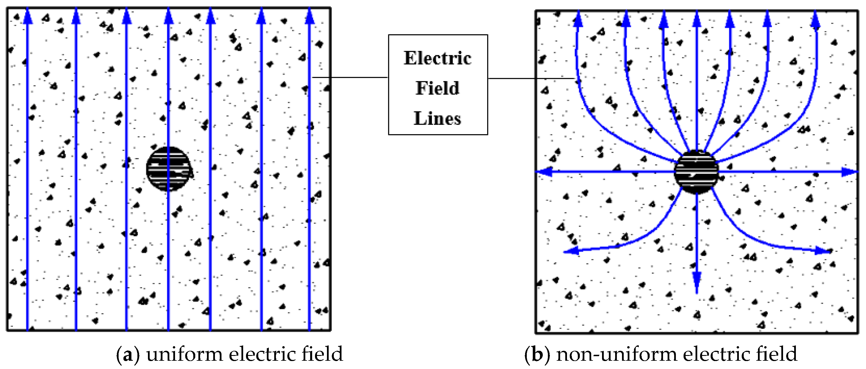
The electrified rail transportation systems, such as high-speed railways and metros, typically operate on direct current (DC) power, with the train-running rail serving as the DC return conductor. As illustrated in Figure 1, the power supply system of the train delivers high-voltage direct current. Current flows from the positive terminal of the power supply, through the train-running rail, and returns via the running track to the negative terminal. Consider the traction current of the electric locomotive as I. If the train-running rail is completely insulated from the ground, all the current should flow through the train-running rail. In fact, multiple electrical leakage points exist between the rails and the surrounding soil, inevitably causing current leakage and forming stray current I1. This stray current can penetrate underground RC structures and be picked up by the steel reinforcement [42,43,44]. Although alternating current (AC) systems can also generate stray current [45], this study primarily focuses on DC-induced stray current due to its significantly higher associated risks compared to AC-induced stray current [46]. The number and distribution of electrical leakage points influence the electric field generated by stray current within the RC structure. This internal electric field distribution affects both the chloride-induced corrosion process and the distribution of chloride ions. To analyze the resulting electric fields, when stray current flows through the rebar, the rebar can be regarded as composed of numerous point charges, with the surrounding soil or adjacent metals acting as planar electrodes [47]. For analytical purposes, this study considers two primary simplified representations of stray current effects, as illustrated in Figure 2: a uniform electric field is assumed for scenarios with numerous, densely distributed leakage points (Figure 2a), while a non-uniform electric field is represented for scenarios with sparse leakage points (Figure 2b).

2.2. Chloride Ingress Model

The essence of the chloride ion transport process lies in the mass transfer of charged particles within the pore solution of porous media, with the main driving forces being diffusion and electromigration. The chloride ingress model adopted in the numerical model of this study is specifically described as follows:
(1) Diffusion of chlorides
Based on Fick’s second law, the classical diffusion model for predicting chloride ion flux density in intact concrete is expressed as
J d = D C x
C t = D 2 C x 2
where Jd is the chloride ion flux per unit area per unit time during the diffusion process (kg·m−2·s). D is the chloride diffusion coefficient in intact concrete (m2/s). C is the partial density of chloride ions (kg/m3). x is the depth (m). t is the corrosion time (s). For cracked concrete, the chloride ion diffusion coefficient in Equations (1) and (2) must be adjusted according to the crack width, as formulated by Equation (3) [49]:
D cr = D w < w 1 16.9 27.4 exp ( 0.0176 w ) w 1 w w 2 D s w > w 2
where Dcr is the chloride diffusion coefficient in cracked concrete (10−10 m2/s), which is determined by regression analysis based on Djerbi’s experimental results when w1ww2 [49]. Ds is the chloride concentration at the exposed surface. w is the crack width (µm). The upper and lower limits of crack width are defined as w1 = 30 µm and w2 = 80 µm in this study [49].
(2) Electromigration of chlorides
The electromigration model of the chloride ion flux density is expressed by the Nernst–Planck Equation [50] in this study:
J e = D z i F E R T C
C t = J e x = D z i F E R T C x
where Je is the chloride ion flux per unit area per unit time during the electromigration process (kg m−2 s). zi is the valence of ions. F = 96,487 C/mol is the Faraday constant. E is the intensity of the electric field (V). R = 8.314 J/(K·mol) is the molar gas constant. T is the temperature (K). The diffusion coefficient, D, is sometimes called the migration coefficient (m2/s), and more details can be found in [51].
(3) Final chloride ingress model used in COMSOL software
The total chloride ion flux J density in intact or cracked concrete is governed by the combination of diffusion and electromigration mechanisms, as follows:
J = J d + J e = D   ( C x z i F E R T C )
C t = J x = D   ( 2 C x 2 z i F E R T C x )
The transient transport behavior of chloride ions in cracked concrete is simulated using COMSOL’s coupled partial differential equation (PDE) module, which can be solved by combining the corresponding boundary conditions and initial conditions. The initial conditions of the concrete boundary exposed to the chloride-ion environment, the insulation boundary not in contact with chloride ions, and the remaining part of the concrete are shown in Equation (8), respectively:
C = C 0 D C x n = 0 C x , 0 = 0
where C0 is the chloride ion concentration in the environment. n is the normal of the boundary surface.

2.3. Finite Element Model

This study utilizes the custom PDE feature in COMSOL software (version 5.4) [52] to simulate multiphysics fields, aiming to model the corrosion process of chloride ions in concrete driven by both diffusion and electromigration. The solution procedure is as follows:
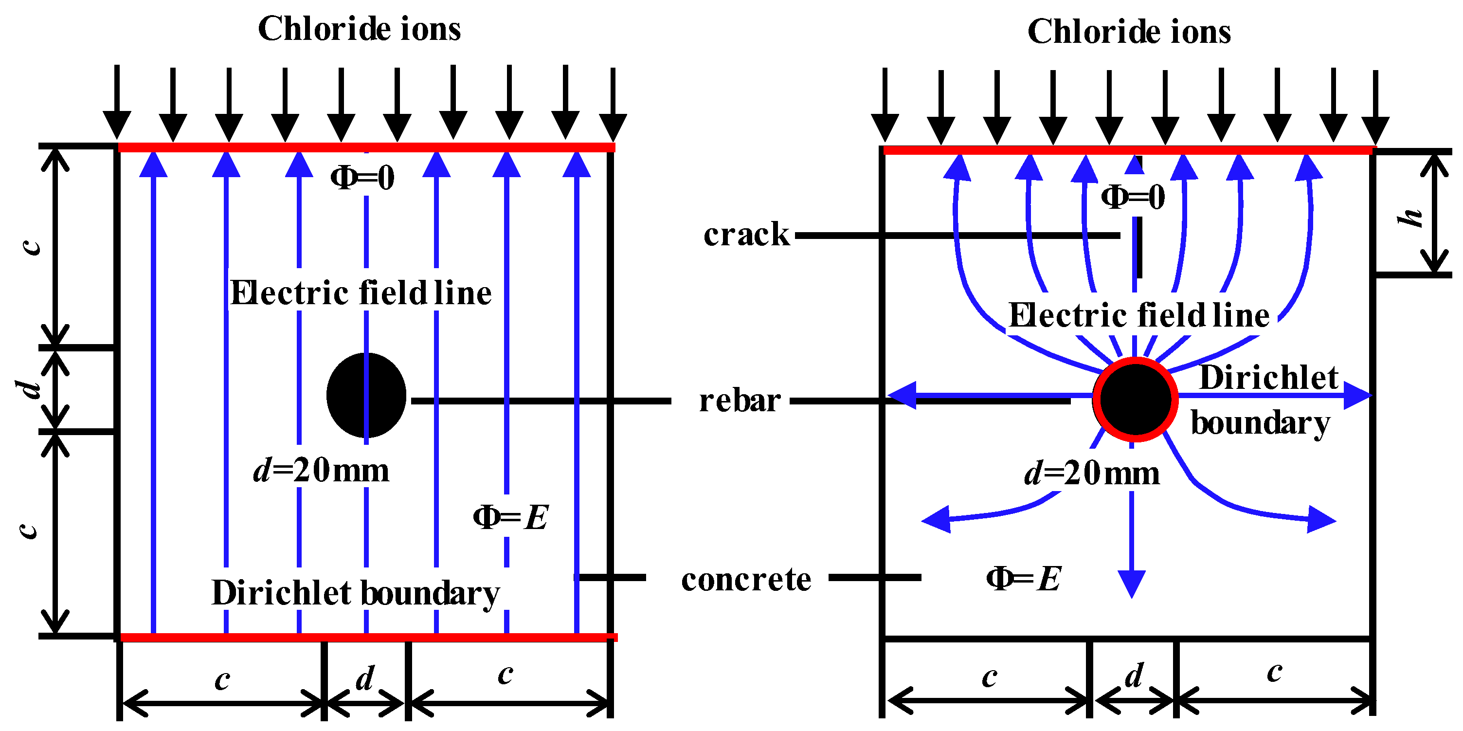
(1) It is assumed that chloride ions ingress concrete from a single direction. To consider the most dangerous situation for RC structures, there is only one uniformly wide crack in the cracked concrete, which is precisely located directly above the rebar, as shown in Figure 3.
(2) The specific values and ranges of finite element (FE) model parameters are detailed in Table 1. To calculate the corrosion initiation time, this study adopts 8.918 kg/m3, determined by Alonso et al. [53], as the chloride threshold Ct (i.e., the percentage of chloride ion mass in concrete). The chloride concentration in the surrounding environment C0 (i.e., the initial boundary condition of the concrete) is set to 16.53 kg/m3 [49].
(3) The stray current effect is realized in COMSOL by applying Dirichlet boundary conditions: fixed potential values are set on the upper and lower surfaces of the concrete to simulate a uniform electric field; fixed potential values are applied on both the surface of the rebar and the upper surface of the concrete to simulate a non-uniform electric field [22], as shown in Figure 3.
(4) Additionally, triangular elements are used for mesh discretization in this study. In order to obtain the most accurate calculation results, the size of the mesh must be ensured to be small enough. So, the mesh is refined in areas with large changes in chloride ion concentration gradients, such as near the crack and around the rebar. This approach adheres to the convergence criteria established by Qiu et al. [54,55] and enhances numerical accuracy, as shown in Figure 4.
Table 1. Values and ranges of numerical model parameters [47].
ParametersValues or Ranges
Rebar diameter d (mm)20
Stray current field intensity E (V)0, 3, 5, 10
Concrete cover thickness c (mm)60, 50, 40, 30
Crack depth h (mm)10, 20, 30, 40
Crack width w (µm)10, 30, 60, 90
Environmental chloride concentration C0 (kg/m3) [49]16.53
Chloride threshold Ct (kg/m3) [52]8.918
Chloride diffusion coefficient D (m2/s) [56]6 × 10⁻¹²

2.4. Model Verification

To validate the accuracy of the numerical model, this study simulates the chloride distribution in intact concrete under both no-electric-field and non-uniform-electric-field conditions, and compares the simulation results with the experimental data from Geng et al. [57], as shown in Figure 5 and Figure 6. The specific parameters for the experiment and FE model are summarized in Table 2. It can be seen from Figure 5 and Figure 6 that under the single effect of diffusion, the erosion distribution of chloride is relatively uniform, with a relatively small penetration depth; under the non-uniform-electric-field conditions, chloride exhibits an approximately quadratic distribution, with significantly higher concentrations near the rebar and an increased penetration depth. Meanwhile, it can be seen from the curve comparison chart that the numerical magnitude and trend of the numerical simulation are very similar to those of the experimental data of Geng et al. [57], but certain differences persisted. Numerical simulation results remained stable, while experimental data exhibited significant fluctuations resulting from experimental uncertainties. This also indicates that the model demonstrates excellent engineering prediction capabilities under simplified assumptions, but the application of complex working conditions requires further multiphysics field coupling. These findings indicate that stray current accelerates chloride migration in concrete, causing chloride to accumulate toward the rebar surface, thereby increasing the chloride concentration at the rebar interface and shortening the depassivation time. In conclusion, the proposed FE model can effectively predict the chloride ingress process in concrete under stray current.

3. The Influence of Stray Current on Chloride Ingress

3.1. Chloride Ingress in Intact Concrete Under Stray Current

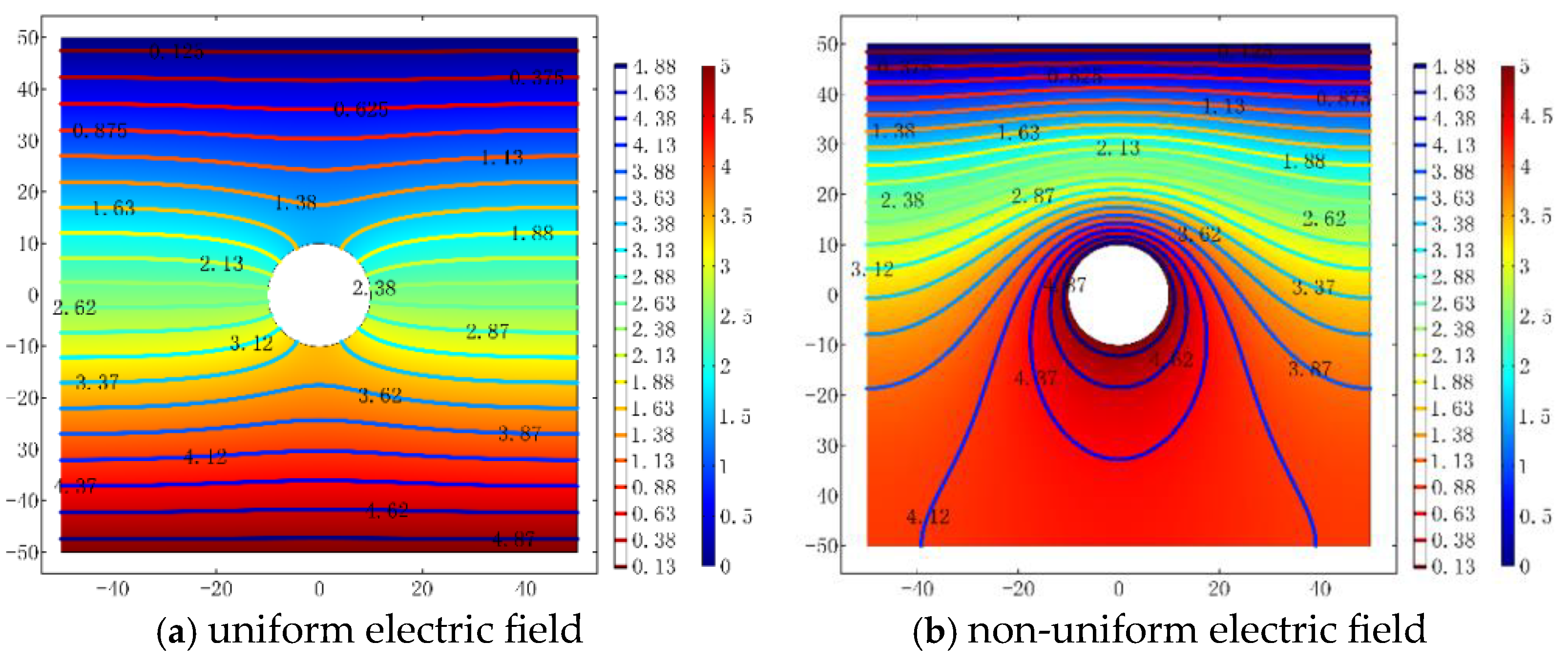
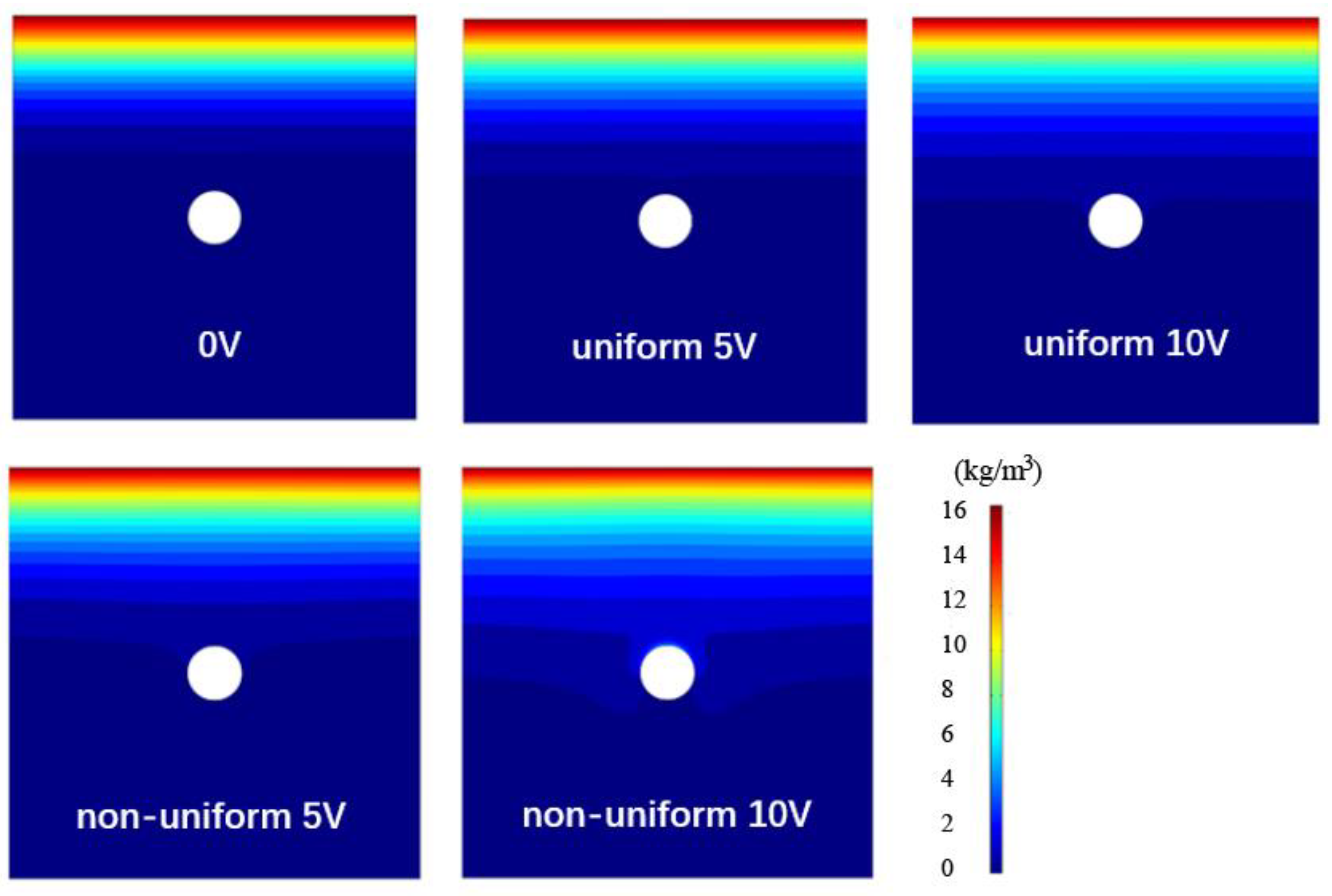
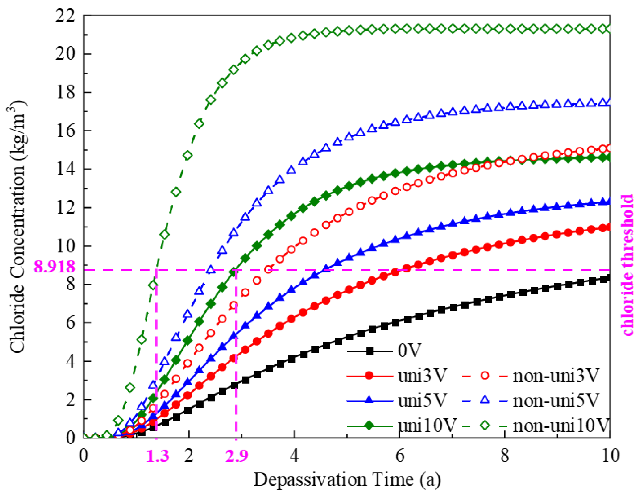
This study numerically simulated the characteristics of uniform and non-uniform electric fields generated by stray current, with their corresponding potential distributions shown in Figure 7. Figure 8 further presents the chloride concentration distributions at a specific time point (t = 100 days) under 0 V (no stray current), 5 V, and 10 V electric field intensities (uniform and non-uniform fields). The results indicate that compared to the no-stray-current condition (0 V), both uniform and non-uniform electric fields significantly alter chloride concentration distributions, with higher electric field intensities leading to faster chloride ingress rates and greater ingress depths. Under the same current intensity, the chloride ingress depth in non-uniform electric fields is substantially larger than in uniform fields, indicating an earlier onset of rebar corrosion. By analyzing the temporal evolution of chloride concentration on the rebar surface under different stray current conditions (Figure 9), it is observed that when subjected to a 10 V electric field, the depassivation times (defined as the time to reach the chloride threshold concentration) for uniform and non-uniform fields are approximately 2.9 years and 1.3 years, respectively, with the non-uniform field exhibiting a depassivation rate approximately 2 times faster than that of the uniform field. Compared to the no-stray-current condition (0 V, approximately 12 years), the depassivation time under 10 V uniform and non-uniform electric fields was reduced by approximately 4 to 9 times. In summary, the application of stray electric fields significantly accelerates the chloride-induced corrosion process, with greater field intensities producing more pronounced effects. Under identical electric field intensities, non-uniform fields exhibit a stronger promoting effect on chloride ingress than uniform fields, resulting in earlier rebar depassivation and higher risks of structural durability degradation.

3.2. Chloride Ingress in Cracked Concrete Under Stray Current

Compared to intact concrete, chloride ingress is significantly influenced by cracks in the concrete, with crack width and depth being the critical factors. Furthermore, stray currents can further accelerate the chloride ingress process, prematurely triggering the corrosion mechanism of rebar and thereby substantially reducing the service life of concrete structures [33]. Therefore, the present study investigates the combined effect of cracks and stray currents on chloride-induced corrosion behavior. The crack depths of the concrete specimens were set at 10, 20, 30, and 40 mm, while the crack widths were varied at 10, 30, 60, and 90 µm. The detailed results are discussed as follows.

3.2.1. Combined Effects of Crack Depth and Stray Current on Chloride Ingress

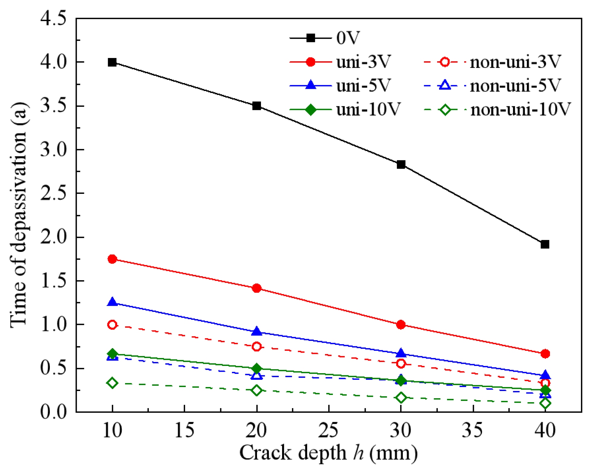
Figure 10 illustrates the influence of different crack depths on the chloride concentration distributions in concrete over 1 year in the absence of stray currents, while Figure 11 further reveals the variation in the depassivation time of rebar under the combined effects of crack depth and stray current. The results demonstrate that as crack depth increases, the rate of chloride ingress into cracked concrete accelerates significantly, leading to a substantial reduction in the depassivation time of the rebar; meanwhile, the depassivation time exhibits an approximately linear relationship with crack width. Under identical electric field conditions, when the crack depth increases from 10 mm to 40 mm, the depassivation time of the rebar is reduced by approximately half. Furthermore, an increase in electric field intensity further significantly shortens the depassivation time, with this effect following a nonlinear decay pattern—particularly pronounced under non-uniform electric field conditions. For instance, at a crack depth of 10 mm, the depassivation time under 10 V uniform and non-uniform electric fields is 0.7 years and 0.3 years, respectively, which is approximately 5.7 times and 13.3 times shorter than the depassivation time without considering stray currents (4.0 years). Moreover, compared to the depassivation time of rebar in intact concrete without stray current influence (approximately 12 years) as described in Section 3.1, the depassivation time of rebar under a 40 mm crack depth and 10 V uniform and non-uniform electric fields is significantly reduced to 0.3 years and 0.1 years, respectively. Therefore, it can be concluded that compared to the influence of individual factors, the chloride ingress rate in cracked concrete is significantly accelerated under the combined effect of crack depth and stray current, and this accelerating effect becomes more pronounced with increasing current intensity and crack depth.

3.2.2. Combined Effects of Crack Width and Stray Current on Chloride Ingress

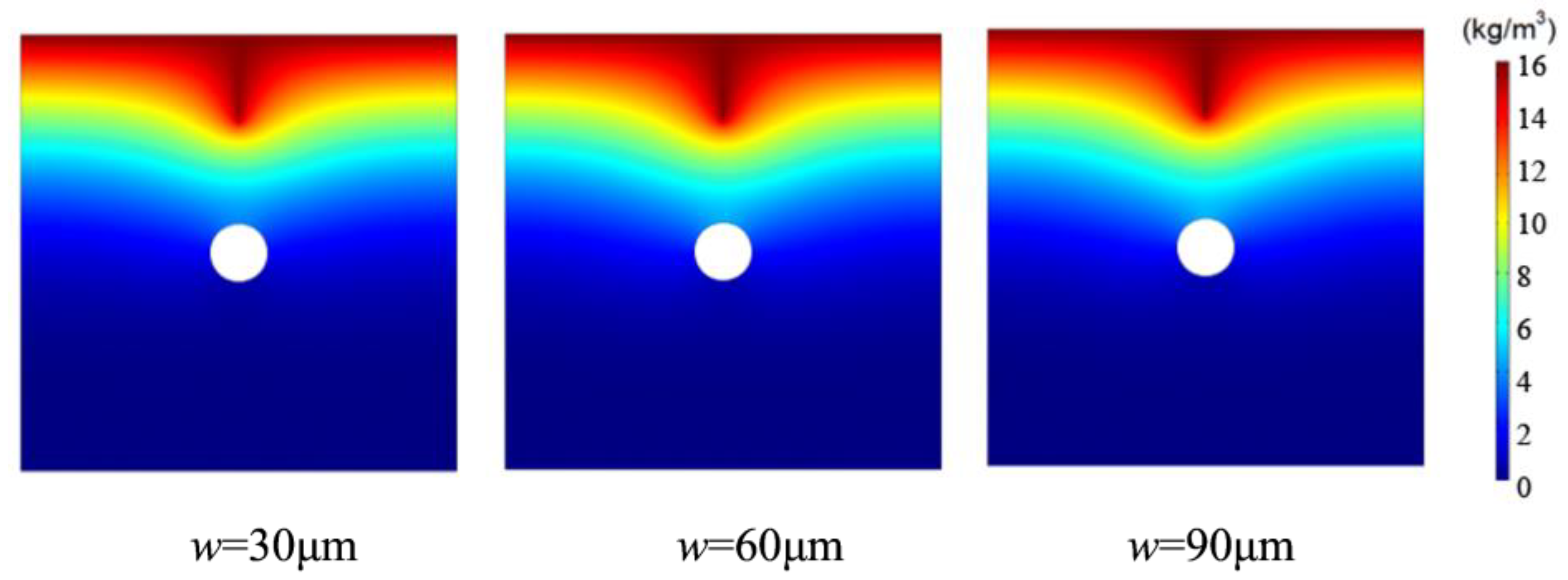
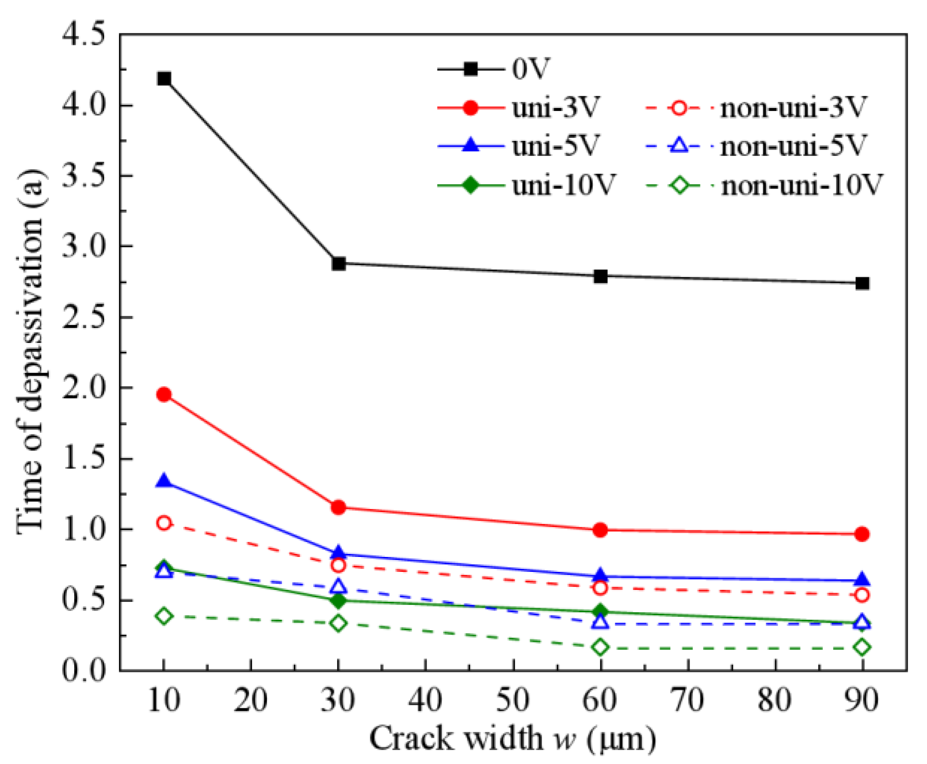
Figure 12 shows the influence of different crack widths on the chloride concentration distribution in concrete over 1 year without consideration of stray current, while Figure 13 reveals the evolution pattern of rebar depassivation time under the combined effect of stray current and crack width. It can be observed that as crack width increases, the depassivation time curve of rebar exhibits a distinct two-stage characteristic: in the first stage (crack width < 30 μm), the depassivation time decreases significantly with increasing crack width. For example, under 3 V uniform and non-uniform electric fields, when the crack width increases from 10 μm to 30 μm, the depassivation time is reduced by 30%~40%; in the second stage (crack width > 30 μm), the depassivation time remains relatively stable because the chloride diffusion coefficient gradually plateaus as the crack width increases. Furthermore, under the same crack width, the depassivation time decreases nonlinearly with increasing stray current intensity, and the depassivation time in non-uniform electric fields is consistently shorter than that in uniform electric fields. Taking a 30 μm crack width as an example, the depassivation time of rebar under 10 V uniform and non-uniform electric fields is 0.6 years and 0.3 years, respectively, which is approximately 4.8 times and 9.7 times shorter than the depassivation time without stray current influence (2.9 years). In summary, within small crack width ranges, the chloride ingress process in cracked concrete is jointly influenced by crack width and stray current; however, once the crack width exceeds a specific threshold, stray current becomes the dominant factor, while the impact of crack width becomes negligible.

3.2.3. Combined Effects of h/c and Stray Current on Chloride Ingress

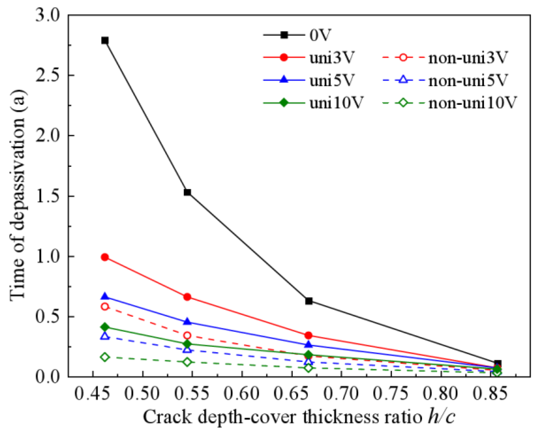
For cracked RC structures, the protective performance of the concrete cover is significantly influenced by crack depth. Thus, the influence of the crack depth/cover thickness ratio (h/c) on the rebar depassivation time in cracked concrete is examined in this section. The crack depth is fixed at 30 mm, while the cover thickness is varied to 65 mm, 55 mm, 45 mm, and 35 mm, resulting in h/c ratios of 0.462, 0.545, 0.667, and 0.857, respectively. Figure 14 presents the variation curve of rebar depassivation time under the combined effects of stray current and h/c ratio. The results indicate that (1) the depassivation time decreases significantly and nonlinearly with increasing h/c ratio; (2) under the same h/c ratio, the depassivation time further decreases with increasing stray current intensity, particularly in non-uniform electric fields. Specifically, without considering stray currents, when the h/c ratio increases from 0.462 to 0.857, the depassivation time sharply decreases from 2.8 years to 0.1 years, a reduction of 28 times; when the h/c ratio is fixed at 0.462, the depassivation time under 10 V uniform and non-uniform electric fields is 0.4 years and 0.2 years, respectively, which is 7 times and 14 times shorter than that without stray currents. In conclusion, the combined effect of stray current and h/c ratio significantly accelerates chloride ingress in concrete. When the h/c ratio approaches 0.9 (i.e., crack depth nears cover thickness), the depassivation time of rebar tends to zero, indicating that the concrete cover loses its protective function for structural durability.

4. Deterioration Coefficient of Stray Current

Stray currents will accelerate the chloride ingress and reduce the service life of underground RC structures. To quantitatively characterize the influence of stray currents on the initiation time of rebar corrosion, this section introduces a deterioration coefficient of stray currents (β), defined as the ratio of the depassivation time of rebar under stray currents to that without stray currents, as expressed in Equation (9):
t e = β · t 0 β = t e t 0
where te is the depassivation time of rebar under stray current action (a), β is the deterioration coefficient of stray current, t0 is the depassivation time of rebar without considering stray current effects (a). Based on the analysis in Section 3, it is evident that the chloride ingress rate is governed by the combined effects of stray current type, intensity, and concrete cover thickness, as well as crack width and depth. Accordingly, this section systematically investigates the variation patterns of β under various parameter combinations and establishes a regression prediction model for β based on the parametric analysis results, with the specific research content outlined as follows:

4.1. Effects of Stray Current and Concrete Cover Thickness on β in Intact RC Structures

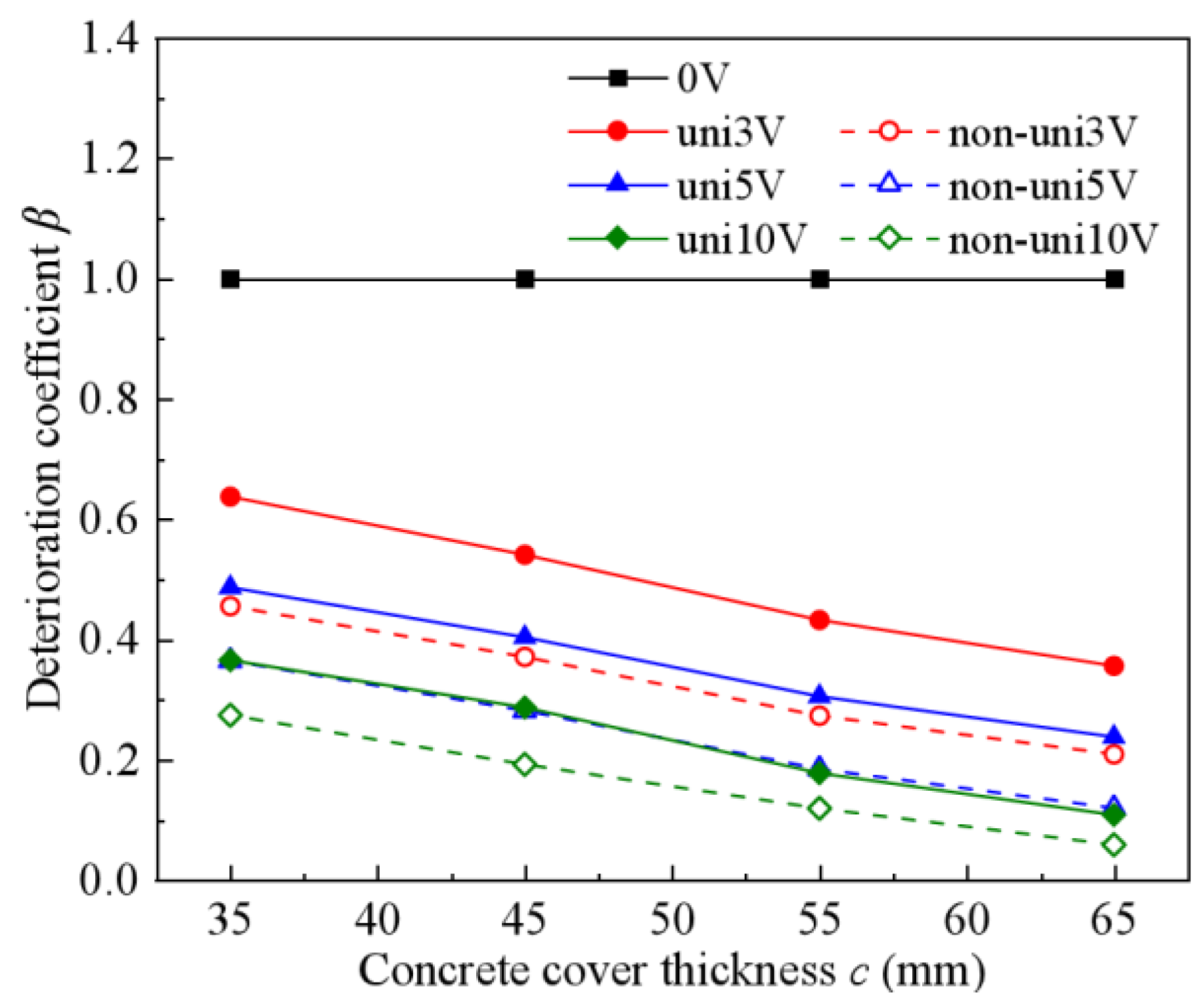
Based on the depassivation time of rebar calculated in Section 3.1, the deterioration coefficient β of intact RC structures is determined using Equation (9), and Figure 15 further illustrates the influence of stray currents and concrete cover thickness on β. The results reveal that β remains constant at 1 in the absence of stray currents, while it exhibits a decreasing trend with increasing stray current intensity or concrete cover thickness, with the impact of stray current intensity being more significant: β decreases significantly with increasing stray current intensity, following an approximate quadratic function relationship, and shows lower values under non-uniform electric fields; meanwhile, β decreases gradually with increasing concrete cover thickness, showing an approximate linear function relationship. The analysis demonstrates that the deterioration coefficient β is considerably more sensitive to stray currents than to the concrete cover thickness. Consequently, a regression prediction model for β can be established, employing a quadratic power function to characterize the relationship between β and stray current intensity, while a linear function is utilized to describe the relationship between β and concrete cover thickness.

4.2. Effects of Stray Current and Concrete Cover Thickness on β in Cracked RC Structures

Similarly, under the condition of a 30 mm crack depth and 60 μm crack width, the deterioration coefficient β of cracked RC structures is calculated, and the influence of stray current and concrete cover thickness on β in cracked RC structure is further given in Figure 16. It can be seen that when stray current effects are neglected, β remains constant at 1; as the stray current intensity or concrete cover thickness increases, β decreases significantly following an approximate quadratic function (dominated by stray current intensity) and gradually decreases following an approximate linear function (dominated by cover thickness), respectively, with β values under non-uniform electric fields being smaller than those under uniform electric fields. Therefore, for cracked RC structures, a quadratic power function and a linear function can still be adopted to characterize the relationship between β and stray current intensity and concrete cover thickness, respectively, thereby establishing a regression prediction model for β.

4.3. Effects of Stray Current and Crack Depth and Width on β in Cracked RC Structures

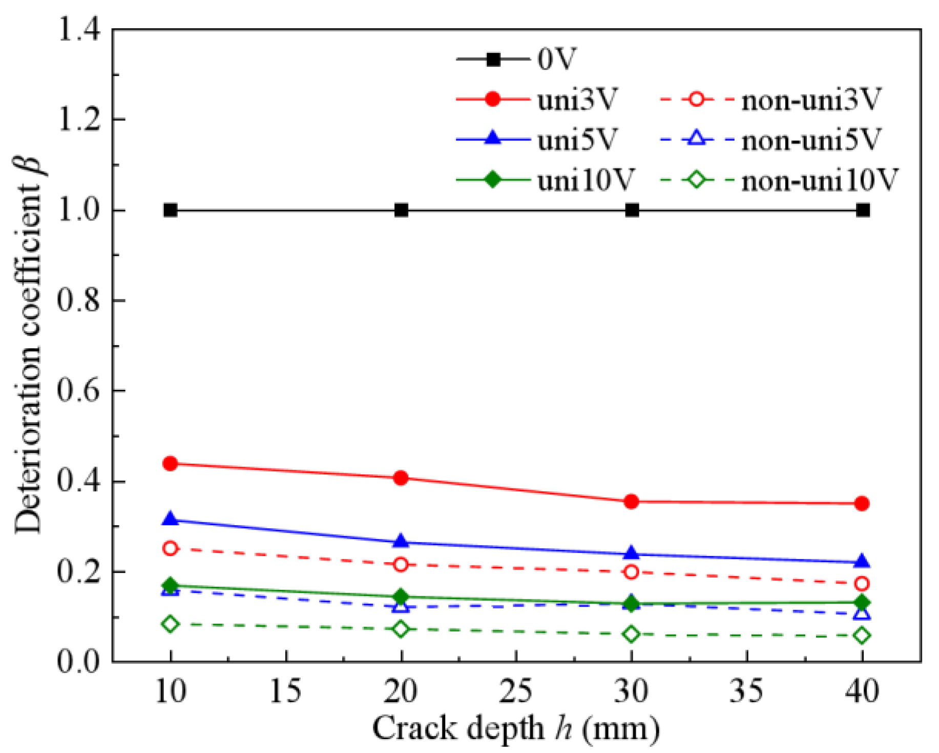
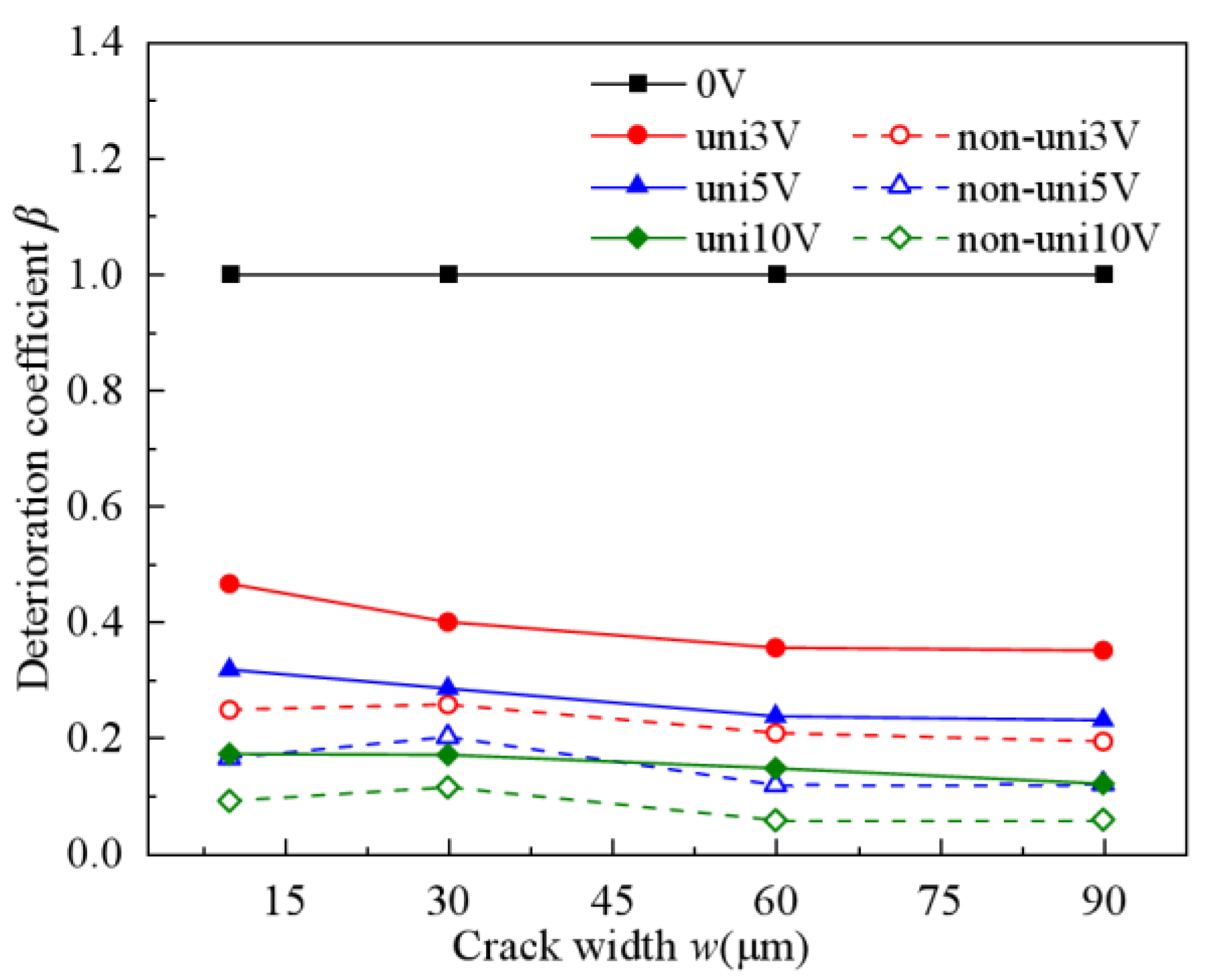
According to the depassivation time of rebar calculated in Section 3.2 and incorporating crack depth and width parameters, the deterioration coefficient β of cracked RC structures is determined. Using a concrete cover thickness of 65 mm, a crack depth of 30 mm, and a crack width of 60 μm as benchmark parameters, Figure 17 and Figure 18 illustrate the influence of stray currents, crack depth, and crack width on the β value, respectively. Consistent with previous findings, β remains constant at 1 when there is no stray current; as stray current intensity increases, β decreases significantly following an approximate quadratic function, with lower β values observed under non-uniform electric fields compared to uniform fields. Notably, variations in crack depth and width exhibit negligible effects on β, with minimal changes observed. Consequently, the regression prediction model for β excludes crack depth and width as influencing factors in this study.

4.4. The Regression Formula for Stray Current Deterioration Coefficient β

Based on the parametric study in Section 4.1, Section 4.2 and Section 4.3, the deterioration coefficient β can be characterized as a function of stray current intensity (E) and concrete cover thickness (c), as expressed in Equation (10). Specifically, β exhibits a quadratic power function relationship with stray current intensity and a linear function relationship with concrete cover thickness. Consequently, the regression prediction model for β is further formulated as Equation (11).
β = t e t 0 = f ( E , c )
β = a 1 μ E 2 + a 2 μ E + a 3 η c + a 4 in   uniform   electric   field b 1 μ E 2 + b 2 μ E + b 3 η c + b 4 in   non-uniform   electric   field
where E is the stray current intensity (V), c is the concrete cover thickness (mm), a1~a4 and b1~b4 are coefficients of regression, and μ and η are dimensionless parameters, defined as μ = 1 V and η = 1 mm . According to the numerical results of parameter analysis in Section 4.1, Section 4.2 and Section 4.3, the regression coefficients in Equation (11) are determined by 1st Opt (First Optimization) software [59], and finally, the regression formula for β shown in Equation (12) is obtained, with R-squares of 0.9525 and 0.9569, respectively.
β = 0.0134 E 2 0.2143 E 0.0028 c + 1.1456 in   uniform   electric   field 0.0182 E 2 0.2698 E 0.0020 c + 1.0871 in   non-uniform   electric   field
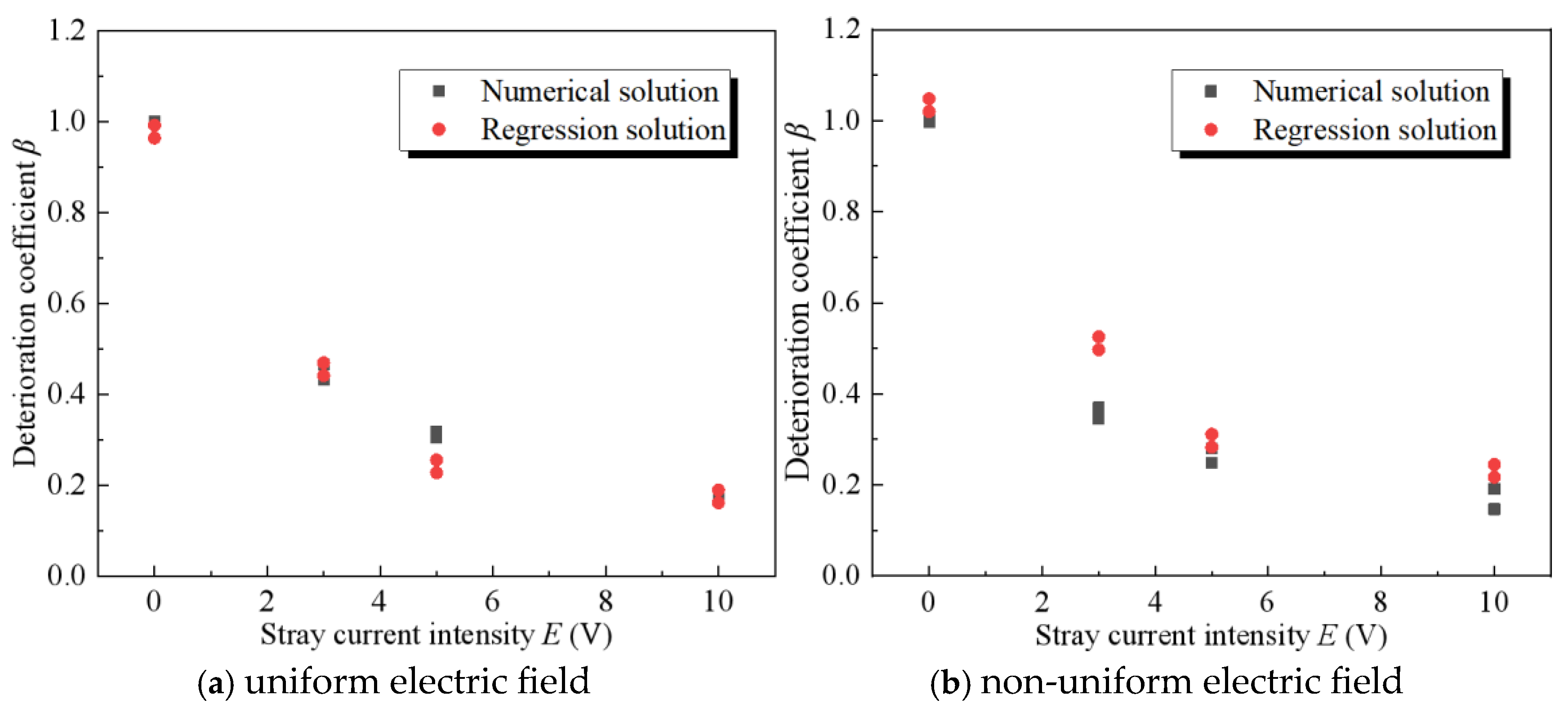
To validate the accuracy of the β regression formula, 16 sets of β values under varying conditions (including intact and cracked concretes, different stray current intensities, varying concrete cover thicknesses, etc.) are selected for comparative analysis between numerical solutions and regression predictions, as shown in Figure 19. The results demonstrate that the predicted values from the β regression formula exhibit good agreement with the numerical calculations, with overall errors maintained within 20% except for a few outlier samples. Consequently, the deterioration coefficient β can effectively characterize, to a certain extent, the influence of stray currents on rebar depassivation time, and can rapidly obtain estimation results consistent with the trend and comparable magnitude of the finite element results. Due to the limited number of numerical samples and the simplification of model assumptions, it is applicable for the preliminary and rough evaluation of the durability of underground RC structures subjected to stray current effects. In the future, the sample size will be expanded, and a more complex modeling framework will be adopted to enhance precision.

5. Conclusions and Discussion

This study systematically investigates the influence of stray currents on chloride ingress behavior in underground RC structures. The main research findings are summarized as follows:
  • Stray current intensity increasingly promotes chloride ingress. Non-uniform stray current fields accelerate ingress 20–50% faster than uniform fields at equivalent intensities.
  • Stray currents nonlinearly shorten rebar depassivation time. Crack depth and width effects are linear, with width becoming insignificant past a threshold. Crucially, depassivation time plunges 40–60% when crack depth-to-cover ratio exceeds 0.6.
  • Stray current intensity dominates depassivation sensitivity, exceeding concrete cover thickness effects and far surpassing crack influences. Research in chloride-stray current environments should focus primarily on current intensity and cover thickness, treating crack parameters as secondary.
  • The proposed regression formula for the deterioration coefficient β quantitatively characterizes the relationship between rebar depassivation time, stray current intensity, and concrete cover thickness. This enables effective durability evaluation of RC structures exposed to stray currents.
The mechanism of chloride-induced corrosion in RC structures is complex, involving numerous influencing factors. This study primarily investigates the effects of stray current, cracks, and concrete cover thickness on chloride ingress, while temporarily excluding the influence of factors such as temperature and humidity. Additionally, the constant applied electric field adopted in this study cannot fully simulate the stray current in practical engineering scenarios, as the stray current intensity in real-world applications varies dynamically over time. Therefore, constructing a numerical model that accounts for comprehensive influencing factors represents a more meaningful research direction for future studies.

Author Contributions

X.C.: Conceptualization, Methodology, Software, Validation, Investigation, Data Curation, Writing—Original Draft, Writing—Review and Editing, Visualization, Supervision. X.L., E.X. and M.C.: Software, Validation, Investigation, Data Curation, Writing—Review and Editing, Supervision. C.M.: Conceptualization, Methodology, Writing—Original Draft, Writing—Review and Editing, Visualization, Supervision. All authors have read and agreed to the published version of the manuscript.

Funding

This research received no external funding.

Data Availability Statement

Data will be made available on request.

Conflicts of Interest

Author Enze Xiang was employed by the company China Tianchen Engineering Corporation Ltd. The remaining authors declare that the research was conducted in the absence of any commercial or financial relationships that could be construed as a potential conflict of interest.

References

  1. Zeng, X.; Wang, Z.; Fan, J.; Zhao, L.; Lin, D.; Zhao, J. Problems of durability and reinforcement measures for underground structures in China. J. Rock Mech. Geotech. Eng. 2011, 3, 250–259. [Google Scholar] [CrossRef]
  2. Angst, U.M. Steel corrosion in concrete—Achilles’ heel for sustainable concrete? Cem. Concr. Res. 2023, 172, 107239. [Google Scholar] [CrossRef]
  3. Yuan, Q.; Shi, C.; Schutter, G.D.; Audenaert, K.; Deng, D. Chloride binding of cement-based materials subjected to external chloride environment—A review. Constr. Build. Mater. 2009, 23, 1–13. [Google Scholar] [CrossRef]
  4. Liang, C.; Cai, Z.; Wu, H.; Xiao, J.; Zhang, Y.; Ma, Z. Chloride transport and induced steel corrosion in recycled aggregate concrete: A review. Constr. Build. Mater. 2021, 282, 122547. [Google Scholar] [CrossRef]
  5. Luping, T.; Nilsson, L.O. Chloride binding capacity and binding isotherms of OPC pastes and mortars. Cem. Concr. Res. 1993, 23, 247–253. [Google Scholar] [CrossRef]
  6. Bouteiller, V.; Tissier, Y.; Marie-Victoire, E.; Chaussadent, T.; Joiret, S. The application of electrochemical chloride extraction to reinforced concrete—A review. Constr. Build. Mater. 2022, 351, 128931. [Google Scholar] [CrossRef]
  7. Guo, B.; Qiao, G.; Niu, D.; Ou, J. Electrochemical corrosion control for reinforced concrete structures−a review. Int. J. Electrochem. Sci. 2020, 15, 5723–5740. [Google Scholar] [CrossRef]
  8. Clemena, G.G.; Jackson, D.R. Trial Application of Electrochemical Chloride Extraction on Concrete Bridgecomponents in Virginia. Bridge Piers. 2000. Available online: https://rosap.ntl.bts.gov/view/dot/19511 (accessed on 1 July 2025).
  9. Chen, X.; Fu, F.; Wang, H.; Liang, Q.; Yu, A.; Qian, K.; Chen, P. A multi-phase mesoscopic simulation model for the long-term chloride ingress and electrochemical chloride extraction. Constr. Build. Mater. 2021, 270, 121826. [Google Scholar] [CrossRef]
  10. Li, Y.; Liu, J.; Wang, Z.; Hao, J. Experimental-numerical analysis of bending behavior of reinforced concrete beam with electrochemical chloride extraction-strengthening. KSCE J. Civ. Eng. 2021, 25, 2991–3007. [Google Scholar] [CrossRef]
  11. De Almeida Souza, L.R.; de Medeiros, M.H.F.; Pereira, E.; Capraro, A.P.B. Electrochemical chloride extraction: Efficiency and impact on concrete containing 1% of NaCl. Constr. Build. Mater. 2017, 145, 435–444. [Google Scholar] [CrossRef]
  12. Saraswathy, V.; Lee, H.S.; Karthick, S.; Kwon, S.J. Extraction of chloride from chloride contaminated concrete through electrochemical method using different anodes. Constr. Build. Mater. 2018, 158, 549–562. [Google Scholar] [CrossRef]
  13. Song, C.; Jiang, C.; Gu, X.; Fang, J. Modeling electrochemical chloride extraction in surface carbonated concrete. J. Clean. Prod. 2024, 460, 142591. [Google Scholar] [CrossRef]
  14. Hu, J.; Zhang, S.; Chen, E.; Li, W. A review on corrosion detection and protection of existing reinforced concrete (RC) structures. Constr. Build. Mater. 2022, 325, 126718. [Google Scholar] [CrossRef]
  15. Chu, H.; Zhang, B.; Zhao, S.; Guo, M.; Liang, Y.; Jiang, L.; Song, Z. Effect of electric current on the stability of bound chloride. Cem. Concr. Compos. 2019, 103, 71–79. [Google Scholar] [CrossRef]
  16. Xue, N. Reinforced concrete structure composition analysis after electrochemical chloride extraction. Int. J. Electrochem. Sci. 2016, 11, 8430–8438. [Google Scholar] [CrossRef]
  17. Liu, Q.; Xia, J.; Easterbrook, D.; Yang, J.; Li, L. Three-phase modelling of electrochemical chloride removal from corroded steel-reinforced concrete. Constr. Build. Mater. 2014, 70, 410–427. [Google Scholar] [CrossRef]
  18. Tang, K.; Wilkinson, S. Corrosion resistance of electrified railway tunnels made of steel fibre reinforced concrete. Constr. Build. Mater. 2020, 230, 117006. [Google Scholar] [CrossRef]
  19. Chen, Z.; Koleva, D.A.; Schlangen, E. Bond of steel-mortar interface interfered by stray current. Cem. Concr. Res. 2021, 150, 106591. [Google Scholar] [CrossRef]
  20. Jin, H.; Yu, S. Effect of DC stray current on rebar corrosion in cracked segment of shield tunnel. Constr. Build. Mater. 2021, 272, 121646. [Google Scholar] [CrossRef]
  21. Wang, C.; Qin, G. Corrosion of underground infrastructures under metro-induced stray current: A review. Corros. Commun. 2024, 14, 23–38. [Google Scholar] [CrossRef]
  22. Zhu, X.; Peng, W.; Xiao, C.; Ma, L.; Hou, J. Effect of electric field intensity on chloride binding capacity of concrete. J. Mater. Res. Technol. 2023, 23, 4466–4478. [Google Scholar] [CrossRef]
  23. Delagrave, A.; Marchand, J.; Ollivier, J.-P.; Julien, S.; Hazrati, K. Chloride binding capacity of various hydrated cement paste systems. Adv. Cem. Based Mater. 1997, 6, 28–35. [Google Scholar] [CrossRef]
  24. Liu, H.; Yang, L.; Kang, K.; Gao, D.; Liu, G.; Zhang, Y.; Zhang, Y. Mechanical properties and corrosion mechanism of steel fiber reinforced concrete (SFRC) subjected to stray current. J. Build. Eng. 2024, 96, 110519. [Google Scholar] [CrossRef]
  25. Chen, Z.; Koleva, D.; van Breugel, K. A review on stray current-induced steel corrosion in infrastructure. Corros. Rev. 2017, 35, 397–423. [Google Scholar] [CrossRef]
  26. Yang, W. Research status of the corrosion effect of stray current on reinforced concrete. China Concr. Cem. Prod. 2025, 2, 19–25. (In Chinese) [Google Scholar]
  27. Zhuang, H.; Cai, Y.; Chen, X.; Wei, H. Review of stray current corrosion on reinforced concrete. Concrete 2019, 6, 31–36. (In Chinese) [Google Scholar] [CrossRef]
  28. Guo, L.; Yang, B.; Chen, B.; Ding, C. Coupling effects of stray current and chloride ion on corrosion resistance of fiber reinforced mortar. J. Water Resour. Archit. Eng. 2016, 14, 11–17. (In Chinese) [Google Scholar] [CrossRef]
  29. Cao, L.; Chu, H.; Zhu, Z.; Liu, D.; Jiang, L.; Zuo, Q.; Li, Y. Migration behavior of sulfate ion in cement-based materials under thecombined action of chloride salt and stray current. Concrete 2020, 5, 19–23. (In Chinese) [Google Scholar] [CrossRef]
  30. Chen, M.; Chen, R.; Chen, Y.; Ma, X.; Kang, X. Stray current induced chloride ion transport and corrosion characteristics of cracked ultra-high performance concrete. Constr. Build. Mater. 2023, 398, 132536. [Google Scholar] [CrossRef]
  31. Lu, T.; Jin, Z.; Chen, Z.; Li, X.; Hu, Y.; Du, Z. Study on corrosion of reinforcement in buried concrete under the action of stray current and chlorine salt. J. Xi’an Univ. Archit. Technol. (Nat. Sci. Ed.) 2023, 55, 484–491. (In Chinese) [Google Scholar] [CrossRef]
  32. Xia, J.; Chen, J.; Li, T.; Shen, J.; Liu, Q.; Jin, W. Modelling the corrosion mechanism of steel bars in chloride-contaminated concrete with transverse cracks. Mag. Concr. Res. 2022, 75, 580–594. [Google Scholar] [CrossRef]
  33. Wang, X.; Ba, M.; Yi, B.; Liu, J. Experimental and numerical investigation on the effect of cracks on chloride diffusion and steel corrosion in concrete. J. Build. Eng. 2024, 86, 108521. [Google Scholar] [CrossRef]
  34. Ying, J.; Yan, H.; Huang, J.; Li, Z.; Chen, B. Simulation of concrete cracking and chloride diffusion under uniaxial compression. J. Build. Eng. 2024, 96, 110329. [Google Scholar] [CrossRef]
  35. Wang, X.; Zhang, L. Simulation of chloride diffusion in cracked concrete with different crack patterns. Adv. Mater. Sci. Eng. 2016, 2016, 1075452. [Google Scholar] [CrossRef]
  36. Zhang, R.; Jin, L.; Liu, M.; Du, X.; Li, Y. Numerical investigation of chloride diffusivity in cracked concrete. Mag. Concr. Res. 2017, 69, 850–864. [Google Scholar] [CrossRef]
  37. Chen, Q.; Zhang, Q.; Zhu, T.; Li, B.; Liu, W.; Yang, H.; Xu, J.; Jiang, Z.; Zhu, H. Coupling effect of concrete cracks and stray current on chloride-induced corrosion of rebar. Constr. Build. Mater. 2024, 449, 138403. [Google Scholar] [CrossRef]
  38. Zhao, P.; Xu, G.; Wang, Q.; Zeng, Z. Corrosion behavior of steel bars in simulated concrete pore solution under the coupling action of chloride salt and DC stray current. Constr. Build. Mater. 2024, 455, 139126. [Google Scholar] [CrossRef]
  39. Yun, Q.; Zhang, S.; Zhao, R.; Wu, J.; Zhu, W. Experimental study on chloride migration in mortar phase of concrete for metro tunnel segment under the coexistence of stray current and salt solution. Concrete 2024, 7, 54–57. (In Chinese) [Google Scholar] [CrossRef]
  40. Wu, P.; Zhu, X.; Xu, L.; Peng, W.; Zhao, G. Effect of stray current coupled with chloride concentration and temperature on the corrosion resistance of a steel passivation film. Electrochem. Commun. 2020, 118, 106793. [Google Scholar] [CrossRef]
  41. Zhang, D.; Huang, Z.; Wang, R.; Yan, J.; Zhang, J. Grouting-based treatment of tunnel settlement: Practice in Shanghai. Tunn. Undergr. Space Technol. 2018, 80, 181–196. [Google Scholar] [CrossRef]
  42. Wang, C.; Fang, Z.; Zhuang, X.; Chen, Q.; Han, K.; Zhou, S. External sulfate attack on cement-based materials in underground structures with the stray current. Constr. Build. Mater. 2025, 465, 140284. [Google Scholar] [CrossRef]
  43. Lapiro, I.; Eid, R.; Kovler, K. Passive protection of reinforced concrete columns against stray currents and chloride attack. Constr. Build. Mater. 2025, 472, 140814. [Google Scholar] [CrossRef]
  44. Chen, Z.; Gao, L.; Cai, X.; Zhong, Y.; Zhang, Y. Evolution of steel-mortar interface undergoing stray current. Constr. Build. Mater. 2023, 409, 134117. [Google Scholar] [CrossRef]
  45. Jones, D.A. Effect of alternating current on corrosion of low alloy and carbon steels. Corrosion 1978, 34, 428–433. [Google Scholar] [CrossRef]
  46. Brenna, A.; Beretta, S.; Bolzoni, F.; Pedeferri, M.; Ormellese, M. Effects of AC-interference on chloride-induced corrosion of reinforced concrete. Constr. Build. Mater. 2017, 137, 76–84. [Google Scholar] [CrossRef]
  47. Xiang, E.; Liu, X.; Lv, B.; Cheng, X. Effects of stray current on chloride ingress in cracked RC structures. Low. Temp. Archit. Technol. 2018, 40, 4. (In Chinese) [Google Scholar] [CrossRef]
  48. Xiang, E. Study on the Corrosion Behaviors of the Exitingpermanent Bolt Structure and Its Durability Evaluation. Master’s Thesis, China University of Petroleum (East China), Qingdao, China, 2019. (In Chinese). [Google Scholar] [CrossRef]
  49. Jin, W.; Yan, Y.; Wang, H. Chloride diffusion in the cracked concrete. In Fracture Mechanics of Concrete and Concrete Structures; Korea Concrete Institute: Seoul, Republic of Korea, 2010; Available online: https://www.framcos.org/FraMCoS-7/07-05.pdf (accessed on 1 July 2025).
  50. Němeček, J.; Kruis, J.; Koudelka, T.; Krejčí, T. Simulation of chloride migration in reinforced concrete. Appl. Math. Comput. 2018, 319, 575–585. [Google Scholar] [CrossRef]
  51. Cerný, R.; Rovnaníková, P. Transport Processes in Concrete; Spon Press: London, UK, 2002. [Google Scholar] [CrossRef]
  52. COMSOL Multiphysics®, Version 5.4. [Computer software]. COMSOL AB: Stockholm, Sweden, 2018. Available online: https://www.comsol.com/comsol-multiphysics (accessed on 1 July 2025).
  53. Alonso, C.; Castellote, M.; Andrade, C. Chloride threshold dependence of pitting potential of reinforcements. Electrochim. Acta 2002, 47, 3469–3481. [Google Scholar] [CrossRef]
  54. Qiu, J.; Feng, D.; Wu, G. A multi-physics dual-phase field model for chloride-induced localized corrosion process and cracking in reinforced concrete. Comput. Methods Appl. Mech. Eng. 2025, 434, 117578. [Google Scholar] [CrossRef]
  55. Wu, J. A unified phasefield theory for the mechanics of damage and quasibrittle failure. J. Mech. Phys. Solids. 2017, 103, 72–99. [Google Scholar] [CrossRef]
  56. Zhu, X.; Zi, G. A 2D mechano-chemical model for the simulation of reinforcement corrosion and concrete damage. Constr. Build. Mater. 2017, 137, 330–344. [Google Scholar] [CrossRef]
  57. Geng, J.; Ding, Q.; Sun, J.; Sun, B. Transport characteristics of chloride ion in concrete with stray current. J. Build. Mater. 2010, 13, 121–124. (In Chinese) [Google Scholar] [CrossRef]
  58. Geng, J. The Research on the Deteriorated Mechanisms of Reinforced Concrete in Stray Currents and Chloride Ion Coexisted Corrosion Environment. Ph.D. Thesis, Wuhan University of Technology, Wuhan, China, 2008. (In Chinese). [Google Scholar] [CrossRef]
  59. 1stOpt (First Optimization)®, Version 7.0. [Computer software]. 7D-Soft High Technology Inc.: Beijing, China, 2016. Available online: http://www.7d-soft.com/ (accessed on 1 July 2025).
Figure 1. Schematic illustration of stray current leakage from a DC railway system and its pickup by rebar embedded in concrete [48].
Buildings 15 03301 g001
Figure 2. Electric field distributions caused by stray currents.
Buildings 15 03301 g002
Figure 3. Schematic diagram of the FE model.
Buildings 15 03301 g003
Figure 4. Mesh discretization of FE models.
Buildings 15 03301 g004
Figure 5. Comparison of chloride distribution under no electric field: numerical results vs. experimental data.
Buildings 15 03301 g005
Figure 6. Comparison of chloride distribution under non-uniform electric field: numerical results vs. experimental data.
Buildings 15 03301 g006
Figure 7. Potential profiles in concrete under E = 5 V.
Buildings 15 03301 g007
Figure 8. Diagrams of chloride concentration under stray current, t = 100 d.
Buildings 15 03301 g008
Figure 9. Chloride concentrations of rebar upper surface under stray current.
Buildings 15 03301 g009
Figure 10. Chloride distributions in cracked concrete with different crack depths without stray current (w = 60 μm, t = 1 year).
Buildings 15 03301 g010
Figure 11. Effects of stray current and crack depth on depassivation time (w = 60 μm, t = 1 year).
Buildings 15 03301 g011
Figure 12. Chloride concentrations in cracked concrete with different crack widths without stray current (h = 30 mm, t = 1 year).
Buildings 15 03301 g012
Figure 13. Effects of stray current and crack widths on depassivation time (h = 30 mm, t = 1 year).
Buildings 15 03301 g013
Figure 14. Effects of stray current and h/c ratios on depassivation time (t = 1 year).
Buildings 15 03301 g014
Figure 15. Effects of stray current and concrete cover thickness on β in intact RC structures.
Buildings 15 03301 g015
Figure 16. Effects of stray current and concrete cover thickness on β in cracked RC structures (h = 30 mm, w = 60 μm).
Buildings 15 03301 g016
Figure 17. Effects of stray current and concrete crack depth on β (c = 65 mm, w = 60 μm).
Buildings 15 03301 g017
Figure 18. Effects of stray current and concrete crack width on β (c = 65 mm, h = 30 mm).
Buildings 15 03301 g018
Figure 19. Verification of the β regression formula.
Buildings 15 03301 g019
Table 2. Parameters of experimental model by Geng et al. [58].
ParametersValues
Rebar diameter d (mm)12
Concrete cover thickness c (mm)30
Stray current field intensity E (V)20
Electrification time t (h)168
Concentration of NaCl (%)8
Concrete mix ratio—Cement (kg/m3)480
Concrete mix ratio—Limestone (kg/m3)1056.9
Concrete mix ratio—Sand (kg/m3)704.6
Concrete mix ratio—Water (kg/m3)151.6
Concrete mix ratio—Chemical admixture (%)1.5
Disclaimer/Publisher’s Note: The statements, opinions and data contained in all publications are solely those of the individual author(s) and contributor(s) and not of MDPI and/or the editor(s). MDPI and/or the editor(s) disclaim responsibility for any injury to people or property resulting from any ideas, methods, instructions or products referred to in the content.