Article

Innovative Seismic Strengthening of Reinforced Concrete Frames with U-Shaped Precast Concrete Wall Panels: Experimental Performance Assessment

Department of Building Research, Korea Institute of Civil Engineering and Building Technology, Goyang-si 10223, Republic of Korea
Buildings 2025, 15(18), 3273; https://doi.org/10.3390/buildings15183273
Submission received: 8 August 2025 / Revised: 6 September 2025 / Accepted: 9 September 2025 / Published: 10 September 2025
(This article belongs to the Section Building Structures)

Abstract

Many existing reinforced concrete (RC) frames with brick infill walls are vulnerable to earthquake damage, particularly when the walls contain window openings that reduce the lateral resistance. This study aims to examine the seismic performance of RC frames strengthened with U-shaped precast concrete (PC) wall panels. In the proposed method, the window-containing brick infill walls within the RC frames are replaced with factory-fabricated U-shaped PC wall panels, thereby converting the infill into a strong and rigid structural element while preserving the openings. The panels are anchored to the RC frame using post-installed anchors inserted through predrilled holes, allowing for rapid and secure installation with minimal on-site work. To validate the method, five full-scale, one-bay, one-story RC frames were constructed and tested under reversed cyclic lateral loading. Three frames were strengthened with U-shaped PC wall panels of varying thicknesses and large openings. Displacement-controlled cycles following ACI 374.1-05 (R7.0) were applied, with three cycles at each drift ratio stage, and no axial load was applied to the columns. Compared with the reference specimen with a U-shaped brick wall, the strengthened frames exhibited up to 3.29 times higher lateral strength, 4.39 times higher initial stiffness, and 4.33 times greater energy dissipation capacity. These findings demonstrate that the proposed strengthening technique significantly enhances seismic resistance while maintaining the architectural openings, offering a practical and efficient solution for upgrading low-rise RC buildings.

1. Introduction

Many low-rise school buildings with reinforced concrete (RC) frames have been constructed worldwide without considering appropriate seismic design principles. Unfortunately, some of these buildings have suffered severe damage or collapsed during earthquakes, leading to significant injuries and loss of life among young students. In earthquake-prone countries, such as China and Indonesia, a substantial number of low-rise RC school buildings remain vulnerable to large-scale damage from future seismic events. Therefore, there is an urgent need to develop a structurally effective, practical, and cost-efficient seismic strengthening technique that can rapidly and reliably enhance building safety.
Numerous studies have focused on techniques for strengthening RC-framed structures, particularly using partial or full RC infill walls [1,2,3]. This approach, the practical application of which has been widely studied, significantly enhances the lateral strength and stiffness of the frames. However, it presents challenges such as extended construction durations and intensive fieldwork, making it difficult to complete within the limited timeframe of school vacation.
To address these issues, many researchers have explored precast concrete (PC) panels as alternatives to RC infill walls. Factory-produced PC panels offer several advantages, including reduced construction time and minimized site work. The dust and odor associated with on-site concrete placement is also eliminated. Furthermore, they are easy to manufacture and install and are highly durable [4,5,6,7]. High-performance fiber-reinforced concrete (HPFRC) has also been utilized in precast infill panels to enhance their cyclic response and energy dissipation characteristics [8]. In parallel with panel-based solutions, member-level strengthening using fabric-reinforced cementitious matrix (FRCM) jackets has also improved the ductility, stiffness, and lateral strength of RC columns under cyclic loading, underscoring the global interest in practical seismic strengthening solutions [9].
Recently, techniques involving the bonding of thin PC panels to brick infill walls have been extensively studied [3]. This method aims to strengthen RC frames with fully infilled walls without incorporating openings. However, low-rise buildings, including school buildings, typically have windows on their external walls. Studies have revealed that when such buildings experience earthquakes, lateral shear cracks can severely damage the structural members surrounding the windows along the longitudinal walls [10].
It has been observed that RC infill walls with openings are less effective in terms of frame strength and stiffness than those without openings [4]. Additionally, experimental results have indicated that using multiple PC panels provides no significant improvement in seismic resistance compared to using a single PC wall panel [6]. Therefore, a U-shaped PC wall panel was selected to retain the opening while significantly enhancing the strength and stiffness of the RC frame. The results demonstrated that the use of this wall panel preserved the opening and substantially improved the seismic resistance of the RC frame. In a previous study, a strengthening technique using a single L-shaped PC wall panel with an opening has been proposed, exhibiting remarkable lateral load resistance performance [11].
In this study, a predrilled anchor connection system that uses post-installed anchors is proposed to enhance the seismic resistance achieved by the strengthening method developed in our previous research. The aim of this innovative technique is to achieve composite behavior between the U-shaped PC panel and RC frames. The proposed method involves anchoring PC wall panels within an RC frame using post-installed anchors inserted through predrilled holes in the PC wall panel. The primary experimental parameters evaluated in this study were the thickness of the PC wall panel and the arrangement of the anchors. To assess the effectiveness of this technique, the lateral strength, lateral stiffness, energy dissipation capacity, and failure mechanisms of the specimens were thoroughly investigated. Displacement-controlled reversed cyclic loading was employed in the experiments in accordance with ACI 374.1-05 (R7.0) [12], with three cycles repeated at each drift ratio stage, and no axial load was applied to the columns (see Section 3.3). The results demonstrated that the predrilled anchor-connected U-shaped PC wall panel provides an effective and practical solution for improving the seismic resistance of RC frames.

2. Structural Strengthening Technique

Strengthening techniques based on U-shaped PC wall panels can preserve the existing windows of a building and improve the resistance to lateral loads through replacement of the RC frames’ existing brick walls while maintaining their shape. As shown in Figure 1, three types of mechanical connections are used to install PC wall panels. These connections can resolve construction errors (up to 50 mm) that occur in the field when installing factory-made PC members and can also significantly shorten the construction time by reducing the construction complexity.
  • Predrilled anchor connection system: PC wall panels are fabricated with predrilled holes. During installation, matching holes are drilled in the RC beams and columns, and threaded anchor rods are bonded into the substrate via injecting an epoxy adhesive after the holes are cleaned [11]. In the laboratory specimens, bar layouts were known, and no reinforcement was cut; for field application to existing frames, rebar scanning (e.g., a cover meter) is recommended so that drilling can be locally adjusted to avoid bars. Post-installed anchors (ϕ24 × 630 mm) were used, with embedment lengths of 210 mm in the RC frame and 420 mm in the PC panel (see Figure 1a). The drill-bit nominal diameter was ϕ28 mm. Holes were cleaned using a blow–brush–blow sequence. The first 2–3 adhesive extrusions were discarded, and the holes were kept dry. HIT-RE 500 anchor injection adhesive was used, and the typical through-anchor pitch was 250 mm at each wall pier.
  • Top multi-anchor connection: Located at the top, this connection resists the maximum shear force during lateral loading using chemical anchors, intersecting connections, and deformed bar stirrups [13,14]. Three post-installed anchors (ϕ24 × 330 mm) were installed at the RC beam in 210 mm deep holes with 150 mm spacing via injecting an adhesive (HIT-HY 200-R); in the PC panel, three cast-in-place anchors (ϕ24 × 330 mm) were provided at the same spacing with an effective embedment depth of 210 mm in the panel and 120 mm into the connection region (see Figure 1e). Three deformed-bar stirrups (D10) were installed.
  • Bottom U-bar connection: Positioned at the bottom side to resist tensile stress, this connection features straight and U-shaped deformed bars for flexible adjustment between the RC columns and PC panels. U-bars were anchored 655 mm into the PC wall panel. Two through-bars (ϕ19) were tied to the U-bars (see Figure 1f), the diameters of which followed the specimen design: D16 for specimens 3 and 4 and D13 for specimen 5. In this study, the “bottom connection” refers to the mid-joint between two factory-made L-shaped PC panels, which are assembled in situ to form a U-shaped panel, allowing for width adjustment to accommodate frame-clearance differences. The connection was filled with high-strength concrete (compressive strength 52–61.4 MPa).
  • Interface bedding and sealing: The perimeter gap was sealed, and low-pressure epoxy bedding was applied at the frame–panel interface. The epoxy was an injectable type (e.g., W-200; medium viscosity; pot life, 40 min at 20 °C; tensile strength, ≥15 MPa; compressive strength, ≥40 MPa; bond strength, ≥6 MPa); materials were selected to ensure watertightness and resistance to corrosion and staining.
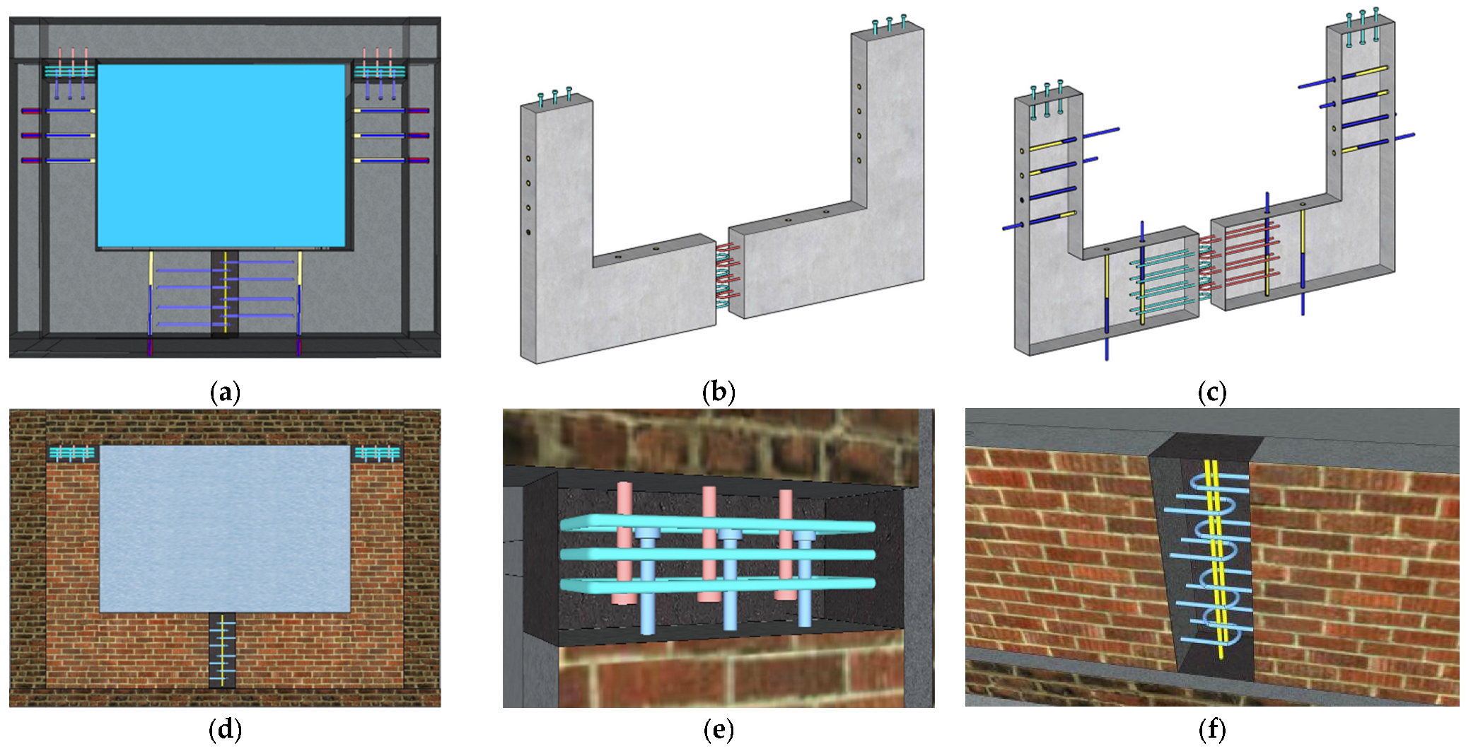
Figure 1. Structural strengthening technique using a U-shaped PC wall panel with an opening: (a) predrilled anchor connection system; (b) U-shaped PC wall panel; (c) PC wall panel with predrilled holes and anchors; (d) PC wall panel fixed with three types of connections; (e) upper multi-anchor connection; (f) lower U-bar connection.
Buildings 15 03273 g001
Since the PC wall panel and the RC frame are both concrete members, the differential thermal strain is negligible. Any long-term shrinkage/creep incompatibility is mitigated by maintaining a sealed perimeter gap and by the continuous, low-pressure epoxy bedding, which distributes interface shear and limits stress concentrations. Lateral force transfer is shared by distributed post-installed anchors rather than by the hard bearing. For field applications, the joint sealant and anchorage should be inspected periodically—initially at one year, then in five-year intervals and following any significant events. If fine interface cracks are observed, local resealing or low-pressure re-injection should be performed.

3. Experimental Work

3.1. Description of Test Specimens

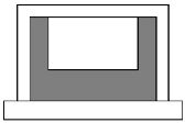
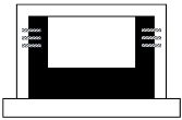
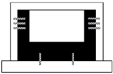
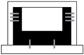
Five full-scale one-bay, one-story RC frames were designed and tested under cyclic lateral loads. The specimens are listed in Table 1. Specimens 1 and 2 served as reference specimens, whereas the remaining three specimens were strengthened with U-shaped PC wall panels using the predrilled anchor connection system on bare frames.
Specimen 1 was an unstrengthened bare RC frame modeled after an exterior beam–column section of a school building based on a standard school blueprint from the 1980s provided by the Korean Office of Education (details are shown in Figure 2). All the specimens shared identical dimensions and reinforcement configurations for the bare frame. The column and beam dimensions were 400 mm × 400 mm and 330 mm × 400 mm, respectively. Each column was reinforced with ten 19 mm diameter deformed longitudinal bars, whereas each beam contained six 19 mm diameter deformed longitudinal bars. Additionally, 10 mm diameter deformed stirrups were installed in both the columns and beams, spaced 150 mm from the ends and 250 mm from the center.
The reference specimen 2 was a bare frame with a U-shaped brick wall. The wall was constructed using hollow bricks (190 mm × 90 mm × 57 mm) in a U-shaped configuration with a thickness of 1B (190 mm) and an English bonding pattern. The size of the opening was designed according to standardized school designs, with a minimum window size of 2900 mm × 1850 mm.
The U-shaped PC wall panel was installed and connected to the RC frames using three types of connections, as described in Section 2. The predrilled anchor connection system (ϕ24 × 630 mm) and wall panel thickness were selected as key experimental parameters (Table 1).
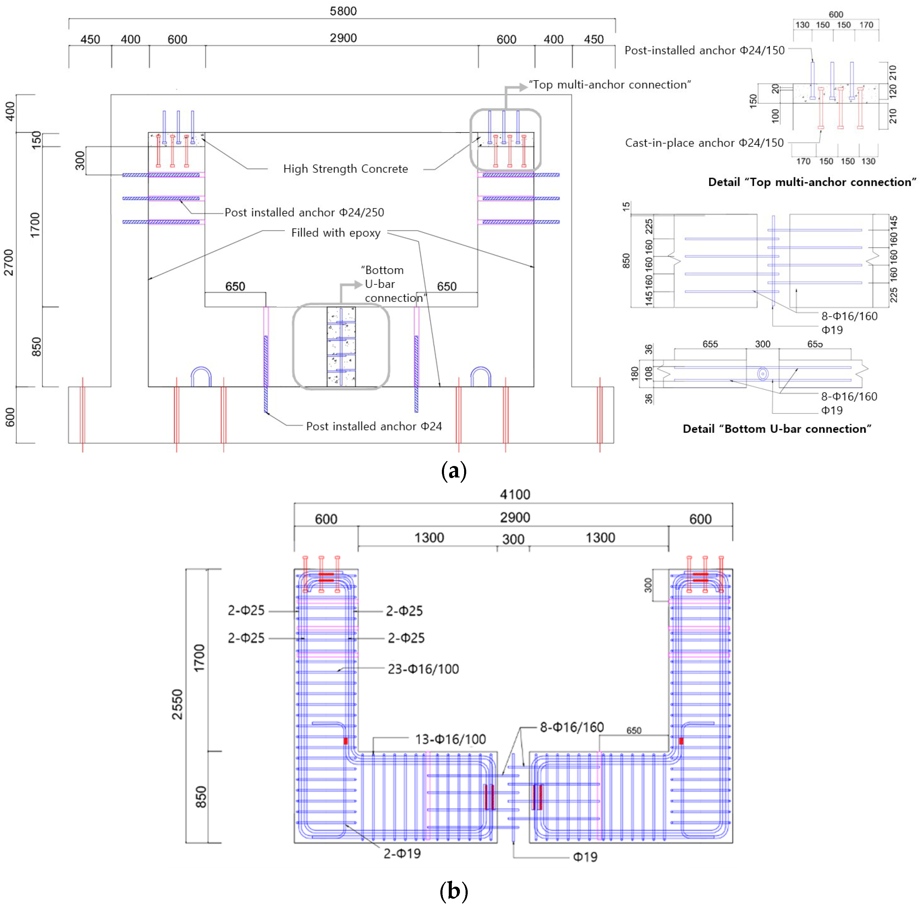
The openings of all the strengthened specimens were identical to those of specimen 2. Additionally, the longitudinal bar spacing and stirrup configurations were consistent across all PC panel specimens. Deformed bars were used for each specimen, with their diameters specified separately for the wall pier and spandrel wall of the PC panels listed in Table 2 (the PC wall panel details of the representative specimen 4 are shown in Figure 3). The anchor arrangements for the predrilled anchor connection system are listed in Table 2. The anchors had a diameter of 24 mm and a total length of 630 mm. Their anchorage lengths were 420 mm in the PC wall panel and 210 mm in the RC frame.
The anchor and rebar arrangements for the top multi-anchor connection and bottom U-shaped rebar connection are summarized in Table 3. The diameters of all the anchors were 24 mm. The anchors of the top multi-anchor connection at the RC beam were post-installed, whereas those at the PC panel were cast-in-place anchors. The anchors were centered on the face of the member to which they were applied. Three deformed bars were used as stirrups for the top connection. At the RC beam, three holes (210 mm in depth) were drilled at 150 mm intervals, into which post-installed anchors (ϕ24 × 330 mm) were placed using anchorage injection. The PC wall panel, equipped with three cast-in-place anchors (ϕ24 × 330 mm) spaced at 150 mm, was then installed within the RC frame.
The U-bars for the bottom connection were also centered on the face of the member in the connection. These U-bars had anchorage lengths of 655 mm in the PC wall panel and of 300 mm into the bottom connection. They were spaced at 160 mm in both the PC spandrel walls and arranged to intersect. Two deformed bars, each 19 mm in diameter, passed through the center of the connection and were tied to the U-bars with steel wires. Finally, high-strength concrete was placed to complete the connection.
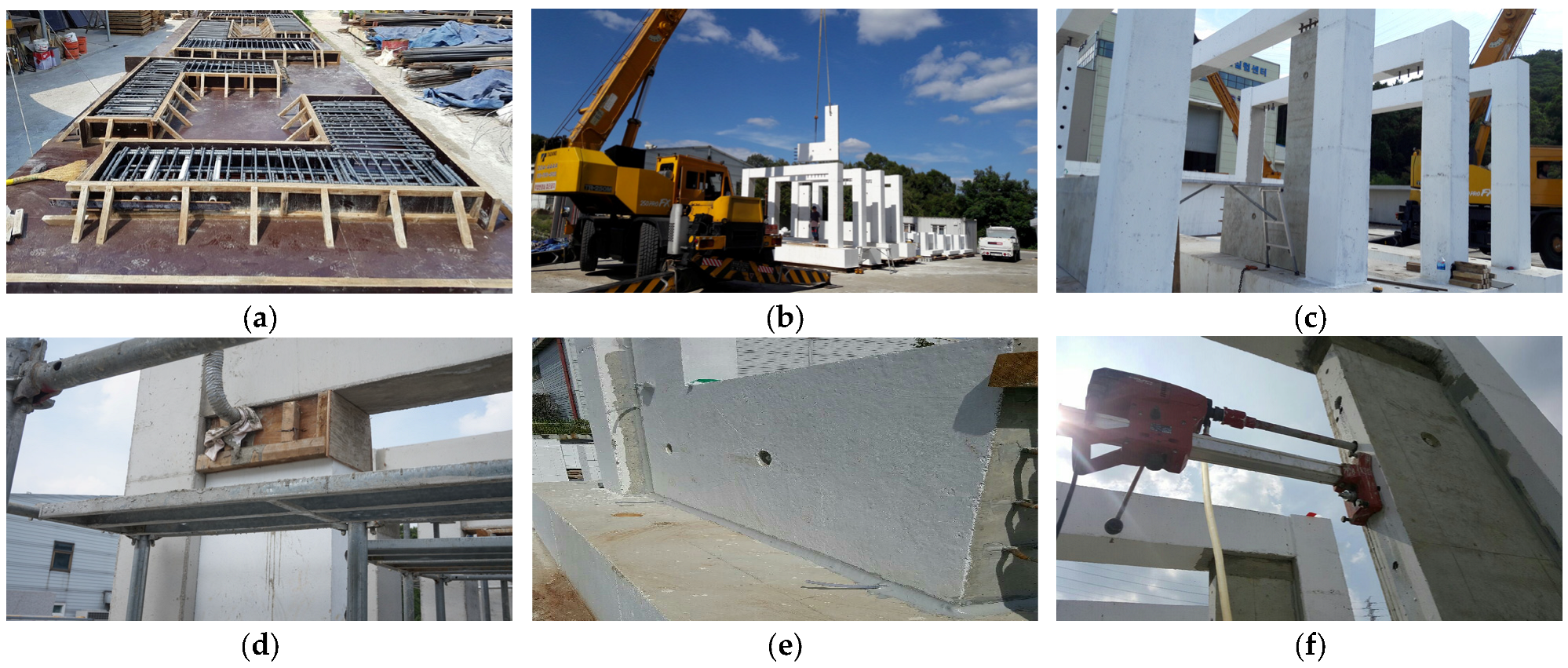
Small L-shaped PC panels were shop-fabricated in molds with reinforcement cages, cast-in-place anchors for the top multi-anchor connection, U-bars for the bottom U-bar connection, and temporary plastic sleeves. The plastic sleeves were withdrawn after the concrete reached early-age strength to form concrete-only holes for the predrilled anchor connection system (Figure 4a). On site, each L-shaped panel was crane-lifted and set within the RC frame to assemble a U-shaped PC wall panel (Figure 4b,c). The top multi-anchor connection and the bottom U-bar connection were then completed using small formwork and filled with high-strength grout (Figure 4d). Next, the perimeter gap was sealed. Low-pressure epoxy bedding was then injected along the frame–panel interface via temporary hoses to form a continuous bedding layer that filled gaps and promoted uniform contact. The assembly was then allowed to cure (Figure 4e). Holes were drilled into the RC members, they were cleaned using the blow–brush–blow technique, and adhesive was injected. Anchors were installed to complete the predrilled anchor connection (Figure 4f). In existing school buildings, when applying the technique proposed in this study, the masonry infill within the RC frame must first be removed (as in Specimen 2) while preserving the openings. The U-shaped PC wall panel can then be installed according to the sequence in Figure 4.
All the specimens were constructed under identical conditions, including the manufacturing environment, date, and materials. Each specimen was tested daily.

3.2. Materials

Concrete with a low compressive strength (17.7 to 20.0 MPa) is commonly used for the exterior RC frames in existing school buildings. For the PC wall panels, relatively high-strength concrete with a compressive strength of 44.8 to 53.5 MPa was employed, while high-strength concrete from Company S with a compressive strength of 52.0 to 61.4 MPa was used at the connections. The compressive strengths of the concrete used in the specimens on the test dates are summarized in Table 1, and the properties of the rebars are listed in Table 4. Both the post-installed (ϕ24 × 630 mm and ϕ24 × 330 mm) and cast-in-place (ϕ24 × 630 mm) anchors were supplied by Hilti Corporation (Schaan, Liechtenstein), through Hilti Korea Ltd.; their properties are listed in Table 5.

3.3. Testing Procedure

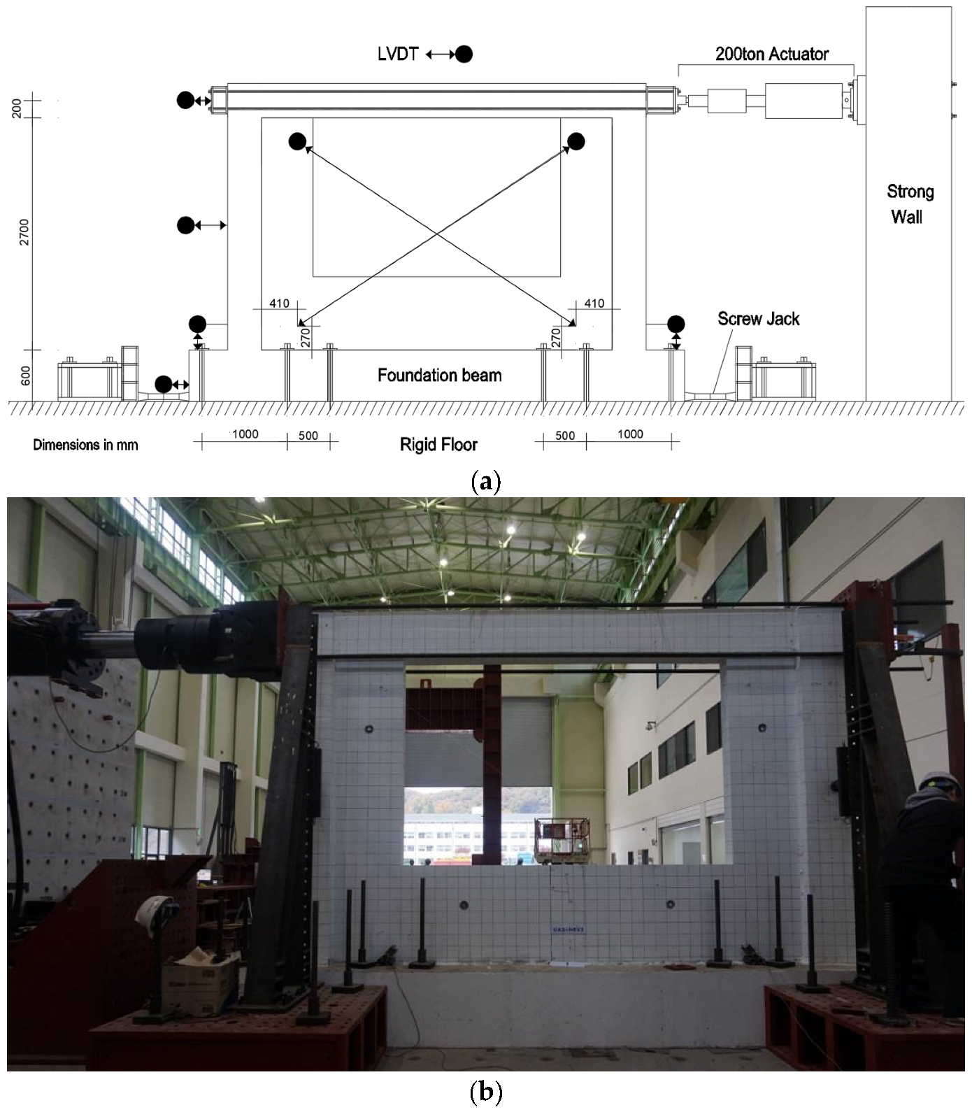
As illustrated in Figure 5, the specimens were placed on the laboratory floor for testing. The setup included a strong floor, a rigid wall, loading equipment, and a data acquisition system. The RC foundations of each specimen were firmly secured to the strong floor using 12 high-tension steel bars, each 32 mm in diameter and capable of withstanding a tensile strength of over 20 tons. Additionally, two screw jacks, each capable of providing a reaction force of up to 400 tons, were installed at both ends of the foundation. Ball jigs were attached to both sides of the RC columns to prevent lateral collapse. Reversed cyclic lateral loading was applied to the center of the upper RC beam end using an actuator with a 200-ton capacity. The tests were conducted using the displacement control method. The story height was set to 2900 mm, measured from the top of the foundation to the center of the upper RC beam, assuming that the foundation was rigidly connected to the reaction floor without deformation.
To observe hysteretic behavior within the elastic range, loading steps corresponding to drift ratios of 0.10% and 0.15% were included. The testing procedure was based on the drift ratios following ACI 374.1-05, R7.0 [12], which are summarized, alongside cycle counts per stage, in Table 6. Displacement-controlled cycles, simulating the drift expected during earthquake conditions, were applied. Three loading cycles were repeated for each drift ratio stage, followed by continuous loading at the same drift ratio. Between amplitude stages, loading was temporarily stopped to allow for recording of crack development and specimen behavior. To control the total test duration, the loading rate was gradually increased: 0.2 mm/s for low amplitudes (stages 1–4), 0.3 mm/s for medium amplitudes (stages 5–8), and 0.5 mm/s for high amplitudes (stages 9–12). However, if the resistance decreased by 20% or more from the maximum load, the specimen was considered to have failed and testing was stopped.
No axial (vertical) load was applied to the columns during the cyclic tests to isolate the frame–panel interaction, consistent with one-story RC frame tests in the literature [1]. Because there was no axial load, the response may be biased toward larger drifts and flexure-dominated behavior; by contrast, in tests with a constant axial load on strengthened infilled frames, a higher lateral strength and initial stiffness but reduced ductility were reported, and the axial level was found to influence the diagonal cracking pattern [6].
To measure the shear displacement of the infill, column curvature, and story drift, linear variable differential transformers (LVDTs) were used, as illustrated in Figure 5. The average shear deformation of the infill was measured using diagonally placed wire displacement transducers. In Figure 5a, the arrows indicate the measurement directions of each transducer. Strain gauges were installed at critical sections of the reinforcement to monitor the yielding of flexural bars during the tests. After each stage of the three cycles, all cracks in the specimens were marked. Additionally, lateral load–story displacement curves were plotted, and failure mechanisms were observed and documented throughout the testing process.

4. Experimental Results

4.1. Specimen Behavior

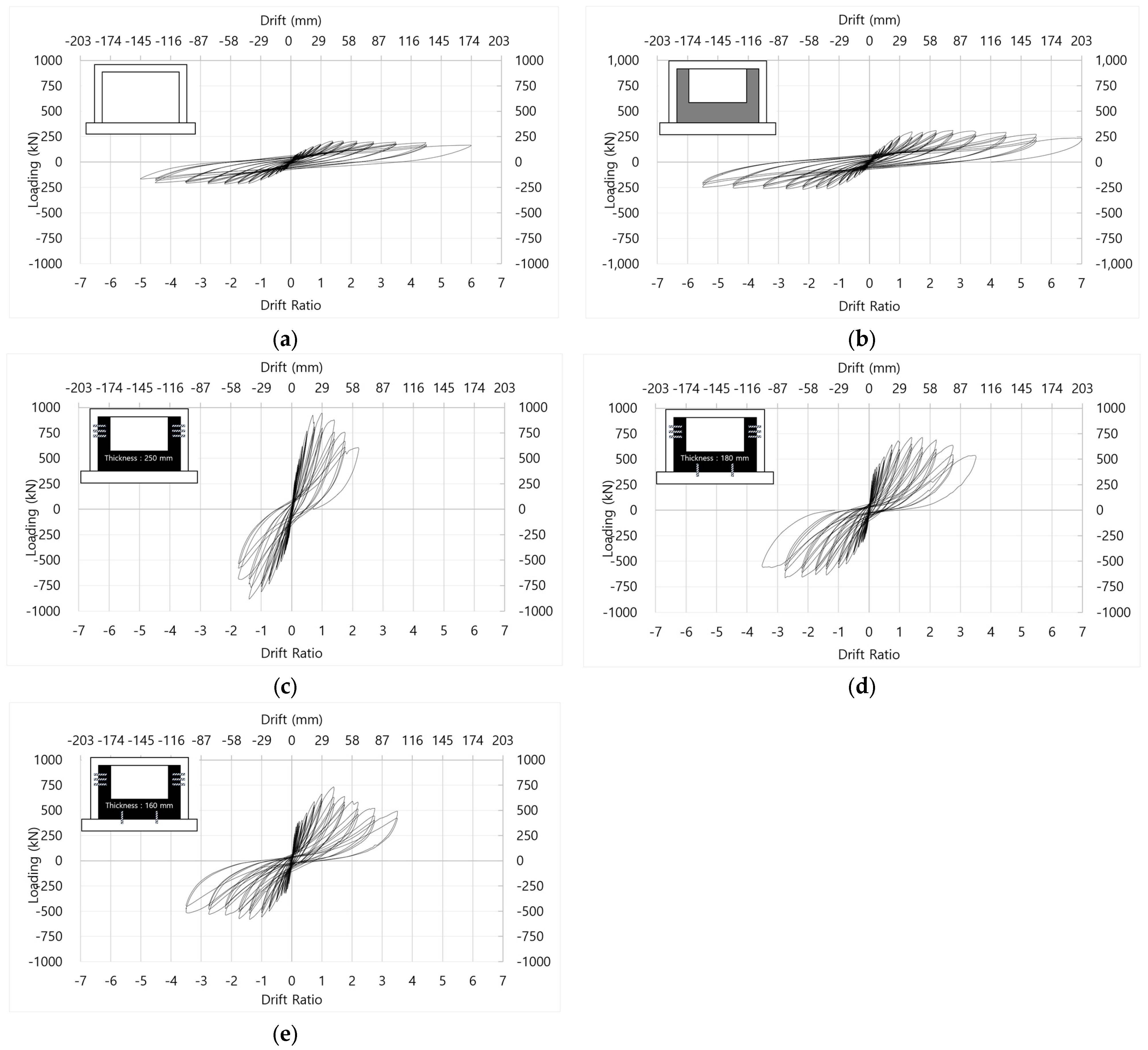
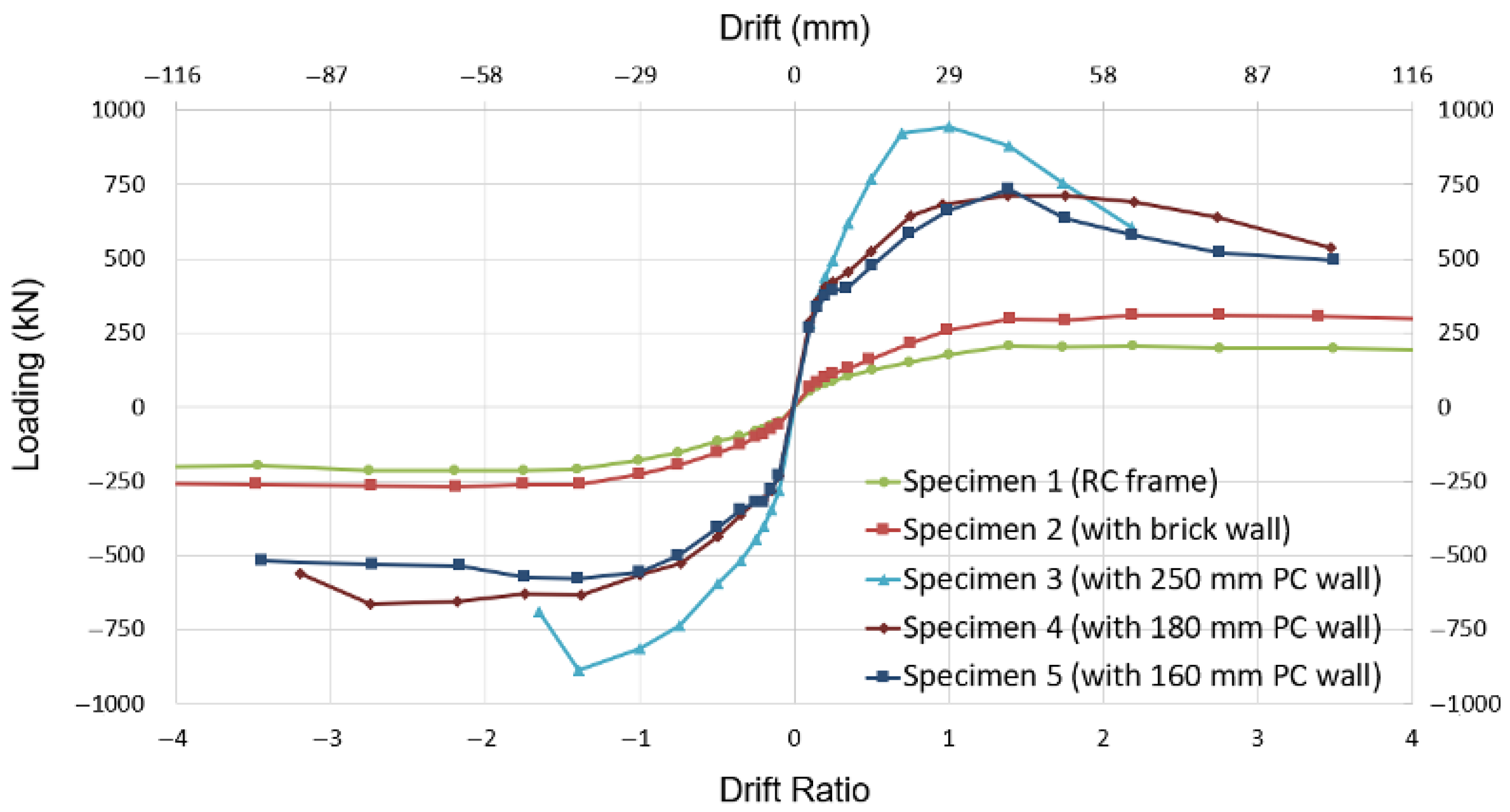
The load–displacement ratio curves plotted from the test data are shown in Figure 6, and the maximum loads and lateral drift ratios at 85% of the maximum post-peak load are summarized in Table 7 for each specimen. The ductility of the specimens was determined based on the lateral drift ratio, and the results were divided into forward and backward cycles. The test results for the specimens strengthened with PC wall panels were compared with those of the reference specimen 2, which featured a U-shaped brick wall commonly used in school buildings.
The first reference specimen 1 (a bare RC frame) exhibited typical frame behavior during the test as well as ductile flexural failure over an extended period at relatively low loads, as shown in Figure 5a. The lateral drift ratio at 85% of the maximum load was 4.4% in both the forward and backward cycles. The load–displacement ratio curve for the second reference specimen 2 (with a brick wall), shown in Figure 5b, was larger than that for specimen 1 (RC frame). Specimen 2 (with a brick wall) recorded a lateral drift ratio of 5.5% at 85% of the maximum load in both the forward and backward cycles, representing a 1.1% increase compared with that for specimen 1 (RC frame).
According to the load–displacement ratio curves in Figure 6c–e, the lateral deformation of the strengthened specimens significantly reduced. In contrast, their lateral strength and stiffness remarkably improved. The measured lateral drift ratios at 85% of the maximum load for the strengthened specimens range between 1.4% and 2.7% in the forward cycles and 1.3% and 3.5% in the backward cycles, which are considerably lower than the 5.5% recorded for reference specimen 2 (with a brick wall).
Experiments with specimen 4 (featuring a 180 mm thick PC wall panel) and specimen 5 (with a thinner 160 mm PC wall panel) showed an 11% difference in wall thickness. Yet, their average lateral drift ratios were similar at 2.7% and 2.65%, respectively. Specimen 3, with a thicker 250 mm PC wall panel, achieved a higher average maximum load compared to specimens 4 and 5. Its average lateral drift ratio was 1.35%, which was 1.35% lower than the average value of 2.7% for the thinner panel specimens.

4.2. Failure Mechanisms

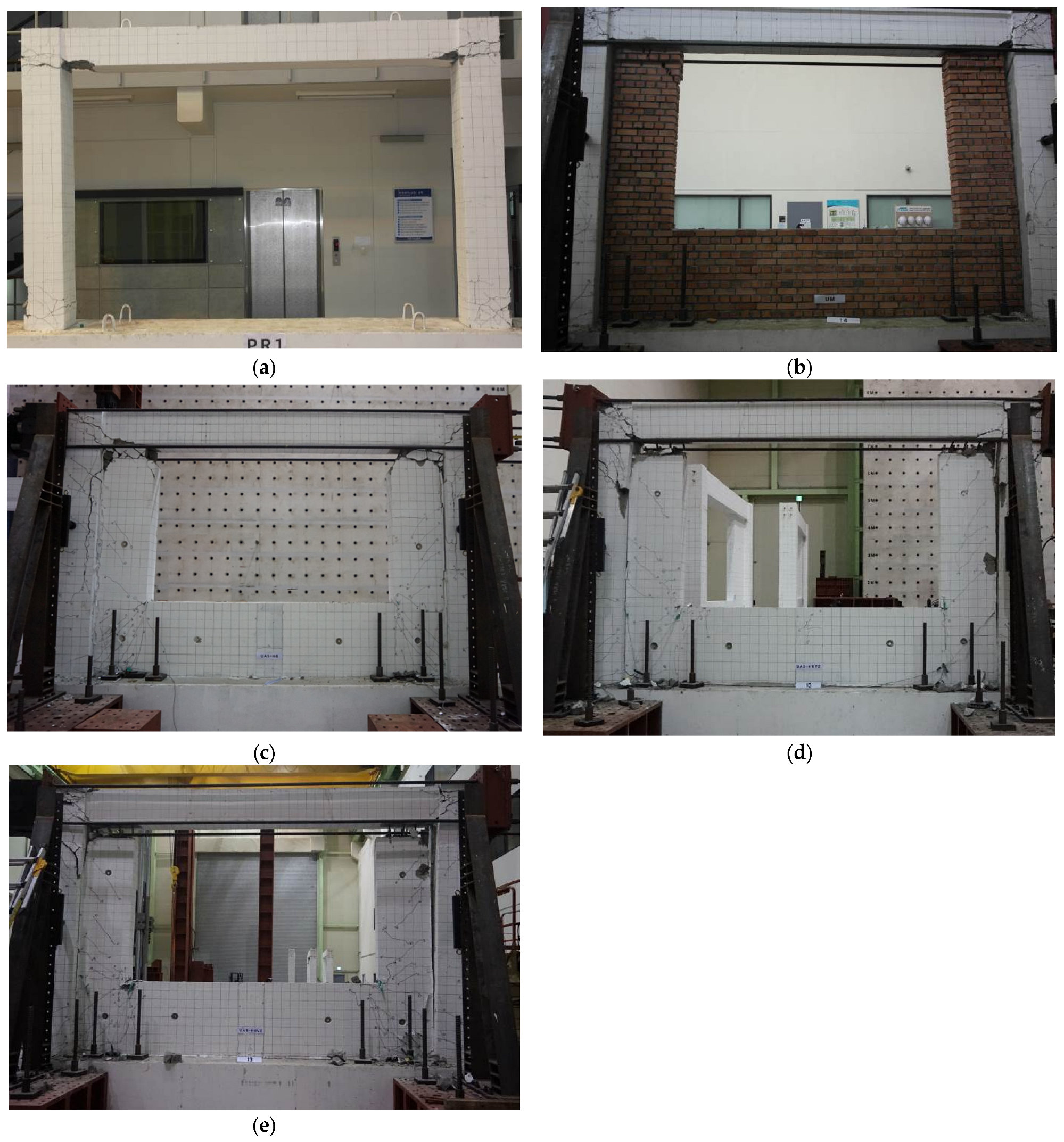
Figure 7 shows photographs of the specimens after failure. For specimen 1 (RC frame), failure occurred because of the column mechanism, as shown in Figure 7a. Plastic hinge behavior was observed, accompanied by flexural and shear failures at the beam–column connections and at the ends of the columns near the foundation. Specimen 2, which included a brick wall, exhibited a behavior similar to that of a frame with a waist-high wall, as shown in Figure 7b. Initially, a long gap formed between the RC column and infill near the sides of the window opening. Although the infill at the sides of the opening was nearly separated from the lower part of the waist-high wall, it did not collapse. The RC frame of specimen 2 (with a brick wall) ultimately failed like that of specimen 1 (RC frame).
For the strengthened specimens (Figure 7c–e), the failure mechanism was consistent across all cases. Cracks first appeared in the internal PC wall panels before the RC frames failed. Flexural and shear cracks typically began at the corners of the window openings, particularly at the bottom-left corners, and numerous cracks spread across the entire wall. The thinner PC wall panels exhibited more severe concrete damage at the corners of the openings than the thicker panels.
After the initial cracking of the PC panels, gaps began to form between these panels and the RC columns. By the end of the test, these gaps widened to approximately 50 mm in size. This gap weakened the composite action between the frame and wall panel. Consequently, the lateral force applied to the RC column was directly transferred to the top multi-anchor connection that fixed the vertical portions of the PC panels to the upper RC beams. These multi-anchor connections eventually failed, causing the concrete at the connections to shatter and fall off. The separation of the U-shaped PC wall panel from the RC column, combined with the failure of the top multi-anchor connection, led to the ultimate failure of the strengthened specimens. At this stage, the strengthened specimens reached their maximum load-carrying capacities in both cycles.

5. Discussion of Results

5.1. Strength and Stiffness

Figure 8 presents the load–displacement envelope curves for the tested specimens, obtained by connecting the peak points of the lateral load–displacement hysteretic curves for each specimen. These envelope curves illustrate the strength and stiffness characteristics of the specimens as well as their overall behavior. In general, the strengthened specimens with U-shaped PC wall panels exhibit significantly higher strengths and initial stiffness than the reference specimens 1 and 2. The strengthening effect was evaluated as the ratio of the performance of each specimen to that of reference specimen 2, which incorporated a U-shaped brick wall.
For specimen 2, the brick wall provided limited frame strengthening. The lateral forward and backward strengths of the RC frame (specimen 1) were 207 and 216 kN, respectively. In contrast, for reference specimen 2 (with a brick wall), these values were slightly higher at 311 and 269 kN, respectively. This resulted in a lateral strength ratio of 0.68 for specimen 1 (the RC frame) relative to specimen 2 (with a brick wall). This minimal improvement indicates that the brick wall alone lacked sufficient resistance to seismic loads, leaving the RC frame highly vulnerable.
After strengthening the RC frame with the U-shaped PC wall panel, the seismic performance of the frame substantially improved. The strengthened specimens exhibited a significantly higher strength and stiffness than specimen 2 (with a brick wall). The maximum strength increased by a factor of 2.30 to 3.04 in forward cycles and 2.15 to 3.29 in backward cycles. The strength improvements were correlated with the thickness of the PC wall panel. Specimen 4 (180 mm thick PC wall panel) had an average lateral strength of 688 kN, whereas that of specimen 3 (250 mm thick PC wall panel) reached 915 kN, a 33% increase. By contrast, specimen 5 (160 mm thick PC wall panel) exhibited a lateral strength of 656 kN, with specimen 4 being 5% stronger. Specimens 4 and 5 employed the same connection strategy, and the difference in the thickness (20 mm) of their PC wall panels was negligible. Consequently, their connection shear strengths were nearly identical, resulting in similar lateral strength values during testing.
The directional asymmetry observed in specimen 5 was analyzed, with peak strengths of 733 kN (forward) and 579 kN (backward). This asymmetry is mainly attributed to direction-dependent contact at the RC frame–PC wall interface: the small initial gaps closed under forward loading, leading to a stiffer compression–strut path. Meanwhile, under reverse loading, the gaps reopened, and load transfer occurred more commonly through the anchors and epoxy, reducing the peak strength. Cumulative cracking after the first peak and minor unavoidable loading eccentricity may also have contributed to this; the panel reinforcement and anchor layout were nominally symmetric, so material anisotropy is unlikely to be the principal cause. This directional difference does not alter the conclusion that the U-shaped PC wall panel significantly increases the lateral strength and stiffness of the RC frame.
The area-normalized strength increased from 3.15 to 3.82 MPa as the panel thickness decreased from 250 to 160 mm (Table 8). This trend matches the observed failure mechanism: after initial cracking, a gap formed at the RC frame–panel interface (up to about 50 mm), weakening composite action and shifting the lateral force to the top multi-anchor connection that fixes the vertical portions of the PC panels to the upper RC beam. Crushing and spalling at this connection governed ultimate failure. Under this mechanism, capacity is primarily controlled by the anchors and their arrangement, rather than the pier section area, so a thinner panel does not exhibit a proportional loss in maximum load.
The initial stiffness of the specimens was calculated as the initial slope of the load–displacement curve in the first half of the forward cycles and served as an index of rigidity improvement. Table 9 shows that the initial stiffness of specimen 1 (RC frame) was 20% lower than that of specimen 2 (with a brick wall). For the strengthened specimens, the initial stiffness ratios ranged from 4.09 to 4.33 compared with that of specimen 2 (with a brick wall). Specimen 3 had an initial stiffness ratio of 4.33, similar to that of specimen 4 (4.39), whereas specimen 5 had a ratio of 4.09. Specimen 4 exhibited a 7% greater stiffness than specimen 5, so the effect of thickness on stiffness was minimal.
At ultimate load, the stiffness of the specimens was evaluated as the average slope of the straight lines connecting the origin to the peak load points in the forward and backward half cycles of the load–displacement curves. For the strengthened specimens, the stiffness ratios at ultimate load range from 3.73 to 5.53. Specimen 3 (250 mm thick PC wall panel) has the highest value at 49.06 kN/mm (ratio 5.53), followed by specimen 4 (180 mm, 35.08 kN/mm, ratio 3.95) and specimen 5 (160 mm, 33.07 kN/mm, ratio 3.73). Although all strengthened specimens exhibit a reduction in stiffness from the initial to the ultimate load stage, the ranking among the specimens remains the same, indicating that panel thickness had only a minor effect on stiffness.

5.2. Energy Dissipation Capacities

Enhancing the energy dissipation capacity is a key objective of strengthening techniques and serves as a crucial indicator of improved earthquake resistance. In this study, energy dissipation was quantified as the area enclosed by the hysteresis load–displacement curve for each cycle. For a consistent comparison across specimens, the cumulative dissipated energy was computed up to Step 10 (drift ratio = 1.75%), which is the last step before specimen 3 met the failure criterion (≥20% strength drop). Specimen 3 satisfied this criterion at Step 11, as seen in Figure 8. The cumulative energy dissipation values are plotted in Figure 9.
Specimens strengthened with U-shaped PC wall panels exhibit a notable increase in energy dissipation capacity, ranging from 3.15 to 4.33 times greater than that of reference specimen 2 (with a brick wall). Thicker PC wall panels are associated with greater energy dissipation, highlighting the positive impact of the increased wall thickness. These results indicate that the proposed strengthening technique significantly enhances the energy dissipation capacity of the frame, providing an effective solution for improving resistance to earthquake loads.

6. Numerical Study: Nonlinear Pushover Analysis

The load–displacement behaviors of the strengthened specimens were evaluated through a nonlinear pushover analysis using the Midas Gen program [15]. This program offers an integrated solution system for building and general structures and provides various functions for both linear and nonlinear structural analyses. The displacement control method was employed for the pushover analysis in this study. In Section 6, a brief calibration-type nonlinear pushover model is presented, which is intended to show that the proposed connection can be represented with standard elements and that the experimental strength envelopes can be reproduced with a simple, practitioner-oriented model. The model is deliberately compact and is not proposed as a comprehensive modeling methodology.
The numerical model was configured to match the maximum load observed in the tests while being simple enough for practical application. For forward loading, single or double braces are added between the PC wall piers and RC columns to simulate partial composite action; for backward loading, these braces are removed to allow independent behavior. Only the PC wall piers were modeled, as the lower part has little influence on the overall response. Figure 10 shows the nonlinear pushover analysis model incorporating these assumptions. Beams and columns were modeled as elastic frame elements with nonlinear plastic hinges at member ends (FEMA hinges in Midas Gen). The U-shaped PC wall was represented by two line “piers” (one per leg), each discretized into two elements with plastic hinges at both ends, using the panel thickness as the section property. Braces were axial-only truss links (single or double), used only for the forward loading branch to emulate partial composite action. Displacement-control pushover was applied at the beam level, with fixed bases. Under backward loading, the predrilled anchor connection allows for limited opening and shear slip at the RC frame–panel interface; bearing is lost, and the composite action disengages. This unilateral contact behavior was represented by removing the braces for the backward branch.
Inputs not explicitly stated follow the software’s standard defaults for the declared element and hinge types (no user overrides). Section properties are derived in closed form from the measured specimen geometry and reported material properties; the model is intended to reproduce global envelopes (initial stiffness and peak lateral strength), with no proprietary or solver-specific tuning.
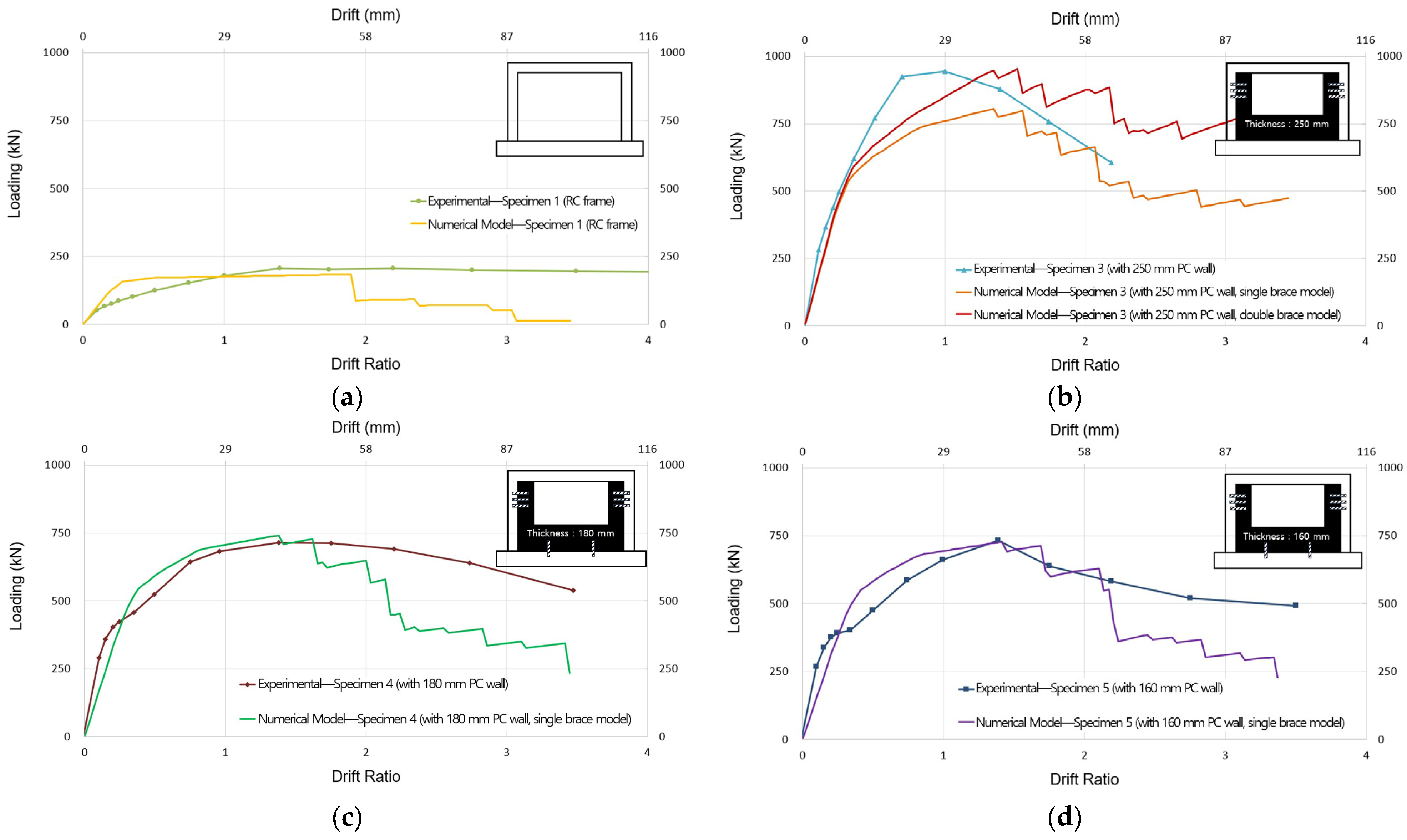
The experimental and numerical results are compared for lateral strength. In practice, a PC wall panel with the required thickness would be used; thus, the analysis model was developed by selecting the optimal configuration with a good lateral strength and stiffness for each thickness. The results of the pushover analysis are compared with the test results, and the ratios of the maximum load and initial stiffness are listed in Table 10 and Figure 11.
The pushover analysis for specimen 1 (RC frame) yields an average maximum lateral load ratio of 1.17 in both the forward and backward cycles, with an initial stiffness ratio of 0.81. For the strengthened specimens, the analysis shows that the ratios of maximum lateral load range from 0.96 to 1.17. In particular, for specimen 3 with a 250 mm thick PC wall panel, both single- and double-brace configurations are modeled, resulting in ratios of 1.17 and 0.99. However, the initial stiffness values from the analysis are lower than the test values for all the strengthened specimens. The ratio of the initial stiffness from the testing to the analysis values ranges from 1.46 to 1.77.

7. Conclusions

Full-scale RC frames with window openings strengthened with U-shaped precast concrete (PC) wall panels were tested, and their behavior was analyzed under reversed cyclic lateral loads. Three strengthened specimens with varying PC wall-panel thicknesses and predrilled anchor connections were fabricated. Based on the test results, the following conclusions were drawn:
  • This strengthening method is an infill technique, which means that the external appearance of a building remains unchanged before and after strengthening. The fabrication of PC wall panels requires minimal on-site work, resulting in a short construction period and lower costs. The proposed seismic strengthening technique significantly enhanced the lateral strength, stiffness, and energy dissipation capacity while maintaining window openings, making it an effective solution for strengthening low-rise buildings.
  • The lateral strengths of specimens strengthened with U-shaped PC wall panel increased by an average of 2.57-fold in forward cycles and 2.63-fold in backward cycles compared with that of reference specimen 2, which had a U-shaped brick wall. In addition, the initial stiffness of the strengthened specimens increased by 4.09- to 4.39-fold.
  • The energy dissipation capacity of the frames strengthened with a U-shaped PC wall panel increased by 3.15- to 4.33-fold compared with that of reference specimen 2 (with a brick wall). This demonstrates that the proposed strengthening technique improves the structure’s resistance to seismic loading.
  • Two key factors primarily influence the composite flexural resistance between the RC column and the U-shaped PC wall panel in the strengthened specimens. The first is the role of the horizontal predrilled anchor connection in enhancing the composite behavior of the RC column and PC wall panel. The second factor is the effect of the thickness and reinforcement of the PC wall panel on its flexural capacity. A greater flexural capacity in the U-shaped PC wall panel resulted in higher lateral strength, stiffness, and energy dissipation, thereby enhancing the seismic resistance of the structure.
  • The strengthened specimens were accurately modeled using nonlinear plastic hinges, braces, and the wall pier of the U-shaped PC wall panel. The maximum lateral load obtained via pushover analysis, conducted using the Midas Gen program, is at most 4% higher than the experimental values when using a double-brace configuration for the 250 mm thick specimen and a single-brace configuration for the other specimens.
  • The design approach adopted in this study is conservative, leading to model results that are lower than the experimental values. A simplified modeling approach is also expected to reduce the design time in practical applications.

Funding

This work is supported by the Korea Agency for Infrastructure Technology Advancement (KAIA) grant funded by the Ministry of Land, Infrastructure, and Transport (grant: RS-2022-00143584).

Data Availability Statement

Data are contained within the article.

Acknowledgments

I would like to express my sincere gratitude to Sung-Yong Yu for his invaluable support throughout this study.

Conflicts of Interest

The author declares no conflicts of interest. The funders had no role in the design of the study; in the collection, analyses, or interpretation of data; in the writing of the manuscript; or in the decision to publish the results.

Abbreviations

The following abbreviations are used in this manuscript:
RCReinforced concrete
PCPrecast concrete

References

  1. Altin, S.; Anil, Ö. An Experimental Study on Reinforced Concrete Partially Infilled Frames. Eng. Struct. 2007, 29, 449–460. [Google Scholar] [CrossRef]
  2. Baran, M.; Aktas, M.; Aykaç, S. Strengthening of Plastered Hollow Brick Infill Walls Using Reinforced Concrete Panels. J. Fac. Eng. Archit. Gazi Univ. 2014, 29, 23–33. [Google Scholar]
  3. Kesner, K.E.; Billington, S.L. Investigation of Infill Panels Made from Engineered Cementitious Composites for Seismic Strengthening and Retrofit. J. Struct. Eng. 2005, 131, 1712–1720. [Google Scholar] [CrossRef]
  4. Akin, A.; Sezer, R. A Study on Strengthening of Reinforced Concrete Frames Using Precast Concrete Panels. KSCE J. Civ. Eng. 2016, 20, 2439–2446. [Google Scholar] [CrossRef]
  5. Baran, M.; Canbay, E.; Canbay, Ö.; Altin, S. Experimental Investigation of Infilled Reinforced Concrete Frames with Openings. ACI Struct. J. 2009, 106, 132–141. [Google Scholar] [CrossRef] [PubMed]
  6. Baran, M.; Okuyucu, D.; Susoy, M.; Tankut, T. Seismic Strengthening of Reinforced Concrete Frames by Precast Concrete Panels. Mag. Concr. Res. 2011, 63, 321–332. [Google Scholar] [CrossRef]
  7. Baran, M.; Tankut, T. Experimental Study on Seismic Strengthening of Reinforced Concrete Frames by Precast Concrete Panels. ACI Struct. J. 2011, 108, 227–237. [Google Scholar] [CrossRef]
  8. Baran, M.; Gunal, E.; Sezer, R. Cyclic Response of Precast High-Performance Fiber-Reinforced Concrete Infill Panels. ACI Struct. J. 2011, 108, 51–60. [Google Scholar] [CrossRef]
  9. John, S.K.; Cascardi, A.; Verre, S.; Nadir, Y. RC-Columns Subjected to Lateral Cyclic Force with Different FRCM-Strengthening Schemes: Experimental and Numerical Investigation. Bull. Earthq. Eng. 2025, 23, 1561–1590. [Google Scholar] [CrossRef]
  10. Arêde, A.; Furtado, A.; Rodrigues, H.; Varum, H. Effect of the Openings on the Seismic Response of an Infilled Reinforced Concrete Structure. Buildings 2022, 12, 2020. [Google Scholar] [CrossRef]
  11. Ha, S.-K.; Yu, S.-Y.; Kim, J.-S. Experimental Study on Existing Reinforced Concrete Frames Strengthened by L-Type Precast Concrete Wall Panels to Earthquake-Proof Buildings. KSCE J. Civ. Eng. 2018, 22, 3579–3591. [Google Scholar] [CrossRef]
  12. ACI 374.1-05; Acceptance Criteria for Moment Frames Based on Structural Testing and Commentary. American Concrete Institute: Farmington Hills, MI, USA, 2014.
  13. Son, G.W.; Ha, S.K.; Song, G.T.; Yu, S.Y. Shear Tests on Subassemblies Representing the Multi-Anchored Connection between PC Wall and RC Frames. KSCE J. Civ. Eng. 2018, 22, 5164–5177. [Google Scholar] [CrossRef]
  14. Park, C.; Ha, S.; Song, G.; Choi, H.; Yu, S. Shear Tests on Subassemblies Representing the Single-Anchored Connection between Precast Concrete Wall Panels and Reinforced Concrete Frames. Buildings 2023, 13, 2632. [Google Scholar] [CrossRef]
  15. MIDAS Civil. Midas Gen 2024, V950; MIDAS Information Technology Co., Ltd.: Seongnam, Republic of Korea, 2024. [Google Scholar]
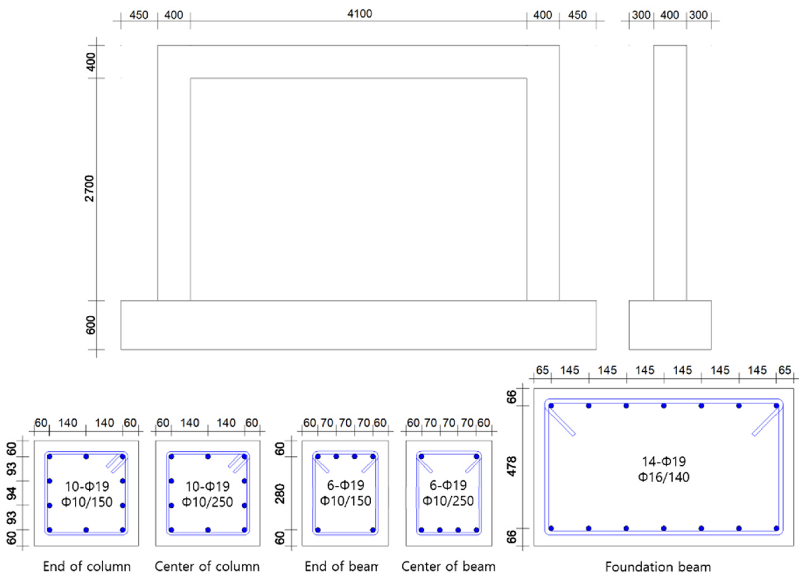
Figure 2. Dimensions and reinforcement of the bare frame (mm).
Buildings 15 03273 g002
Figure 3. Dimensions and reinforcement of a representative specimen strengthened by a U-shaped PC wall panel (mm): (a) RC frame with U-shaped PC wall panel; (b) PC wall panels.
Buildings 15 03273 g003
Figure 4. Fabrication and installation sequence: (a) shop fabrication: reinforcement, cast-in-place anchors, U-bars, sleeves; (b) first L-panel placed in RC frame; (c) second L-panel set to form U-shaped panel; (d) grouting: top multi-anchor and bottom U-bar connections; (e) perimeter sealing, low-pressure epoxy bedding, curing; (f) predrilled anchor connection: drill–clean–adhesive–anchor.
Buildings 15 03273 g004
Figure 5. Installation diagram of the test specimen (mm): (a) arrangement of measuring devices on the specimen; (b) specimen test setup.
Buildings 15 03273 g005
Figure 6. Experimental results: comparison of load–displacement curves: specimen (a) 1 (RC frame); (b) 2 (with a brick wall); (c) 3 (with a 250 mm thick PC wall panel); (d) 4 (with a 180 mm thick PC wall panel); (e) 5 (with a 160 mm thick PC wall panel).
Buildings 15 03273 g006
Figure 7. Specimens after the test: (a) specimen 1 (RC frame); (b) specimen 2 (with a brick wall); (c) specimen 3 (with a 250 mm thick PC wall panel); (d) specimen 4 (with a 180 mm thick PC wall panel); (e) specimen 5 (with a 160 mm thick PC wall panel).
Buildings 15 03273 g007
Figure 8. Load–displacement envelope curves of specimens.
Buildings 15 03273 g008
Figure 9. Energy dissipation capacity graphs of specimens.
Buildings 15 03273 g009
Figure 10. Nonlinear pushover analysis model of the frame strengthened with U-shaped PC wall panel.
Buildings 15 03273 g010
Figure 11. Comparison of experimental and numerical strength envelope curves of the specimens: (a) specimen 1 (RC frame); (b) specimen 3 (with a 250 mm thick PC wall panel); (c) specimen 4 (with a 180 mm thick PC wall panel); (d) specimen 5 (with a 160 mm thick PC wall panel).
Buildings 15 03273 g011
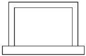
Table 1. Properties of specimens.
Specimen No.Configuration 1,2,3Wall Thickness
(mm)
Concrete Compressive Strength (MPa)
FrameInfill WallConnection
1Buildings 15 03273 i001-20.5--
2Buildings 15 03273 i002190
(Brick wall)
17.7--
3Buildings 15 03273 i003250
(PC wall panel)
18.044.861.4
4Buildings 15 03273 i004180
(PC wall panel)
19.453.553.3
5Buildings 15 03273 i005160
(PC wall panel)
20.051.152.0
1 Gray marks indicate an infill brick wall. 2 Black marks indicate infill PC wall panels. 3 Diagonal bars indicate the predrilled anchor connection system.
Table 2. U-shaped PC wall panel reinforcement and predrilled anchor connection system.
Specimen
No.
U-Shaped PC Wall Panel 1
Longitudinal Bar (No.–Dia) (mm)
and Stirrup (Dia/Spacing) (mm)
Predrilled Anchor Connection System Anchor (No.–Dia/Spacing) (mm)
Wall PierSpandrel WallHorizontal 2Vertical 3
1----
2----
38-25 and 16/1008-25 and 16/1003-24/250-
48-25 and 16/1008-25 and 16/1003-24/2502-24/1600
58-22 and 13/1008-22 and 13/1003-24/2502-24/1600
1 Each wall pier and the spandrel wall had a column-type reinforcement layout. 2 Each wall pier was anchored to the column using horizontal predrilled holes and anchors. 3 The spandrel wall was anchored to the foundation beam using vertical predrilled holes and anchors.
Table 3. Top multi-anchor connection and bottom U-bar connection.
Specimen
No.
Top Multi-Anchor Connection 1
Anchor (No.–Dia/Spacing) (mm)
Bottom U-Bar Connection 2
Bar (No.–Dia/Spacing) (mm)
At RC Beam 1At PC Wall Pier 2At Right PC WallAt Left PC Wall
1----
2----
33-24/150 13-24/150 24-16/1604-16/160
43-24/150 13-24/150 24-16/1604-16/160
53-24/150 13-24/150 24-13/1604-13/160
1 Sets of six ϕ24 anchors were arranged on each side, with cast-in-place anchors for wall piers and post-installed anchors for RC beams. 2 Four U-bars were placed on both sides of the spandrel wall to form the bottom center connection.
Table 4. Properties of the reinforcing bars.
Bar No.Bar Diameter (mm)Tensile Strength (MPa)Yield Strength (MPa)
109.5645.8516.8
1312.7660.7544.2
16 115.9654.4536.7
16 215.9675.2556.4
1919.1644.5508.5
2222.2842.0705.7
2525.4766.5627.5
1 Location: stirrup for RC foundation. 2 Location: bottom U-bar connection.
Table 5. Properties of the anchors.
Anchor No.Anchor PropertyTensile Strength (MPa)Yield Strength (MPa)
24 1Cast-in-place 2450350
24 1Post-installed 3500400
1 The effective cross-sectional area of the ϕ24 anchor was 354 mm2. 2 The cast-in-place anchors were used at the PC wall pier face in the top multi-anchor connection. 3 The post-installed anchors were used on the bottom face of the RC beam in the top multi-anchor connection and also in the predrilled anchor connection system.
Table 6. Loading sequence 1.
StepDrift (%)Displacement (mm)Loading Rate (mm/s)Period (s)Loading Frequency (Hz) 2Duration (s)
10.102.900.2600.0167180
20.154.350.2900.0111270
30.205.800.21200.0083360
40.257.250.21500.0067450
50.3510.150.31400.0071420
60.5014.500.32000.0050600
70.7521.750.33000.0033900
81.0029.000.34000.00251200
91.4040.600.53360.00301008
101.7550.750.54200.00241260
112.2063.800.55280.00191584
122.7579.750.56600.00151980
133.50101.5014200.00241260
144.50130.5015400.00191620
1 Sequence adapted from ACI 374.1-05 (R7.0). 2 Three cycles per drift step; frequency = 1/period.
Table 7. Summary of the experimental results.
Specimen
No.
Forward CyclesBackward CyclesMode of Failure
Ultimate Load
(kN)
Ratio 1
(%)
Drift Ratio 2
(%)
Ultimate Load
(kN)
Ratio 1
(%)
Drift Ratio 2
(%)
12070.674.42160.704.4Column mechanism
23111.005.52691.005.5Column mechanism 3
39453.041.48853.291.3Separation from RC column 4
47142.302.76622.462.7Separation from RC column 4
57332.361.85792.153.5Separation from RC column 4
1 Ratio of maximum load to that of the reference specimen (bare frame with a brick wall). 2 Lateral drift ratio at 85% of maximum load post-peak. 3 The reference specimen showed a continuous gap between the RC column and the wall pier. 4 Strengthened specimens failed by separation from RC columns after PC wall panel cracking.
Table 8. Area-normalized lateral strength using the PC wall pier-only shear area.
Specimen No.Area (mm2) 1Maximum Load (kN) 2Strength Per Unit Panel Area (MPa) 3
3300,0009453.15
4216,0007143.31
5192,0007333.82
1 Maximum load (kN): from Table 6. 2 Pier-only shear area (mm2): panel thickness × 2 × wing width per single pier. 3 Strength per unit panel area: maximum load/area (MPa).
Table 9. Initial stiffness of the specimens.
Specimen No.Initial (kN/mm)Ratio 1At Ultimate Load (kN/mm)Ratio 2
118.310.807.220.81
222.761.008.871.00
398.644.3349.065.53
499.904.3935.083.95
592.984.0933.073.73
1 Ratio of initial stiffness to that of reference specimen 2 (bare frame with a brick wall). 2 Ratio of stiffness to that of reference specimen 2 (bare frame with a brick wall) at ultimate load.
Table 10. Comparison of experimental and numerical results.
Specimen
No.
Maximum Load (kN)Initial Stiffness (kN/mm)
ExperimentalNumericalRatio 3ExperimentalNumericalRatio 3
12161841.1718.3122.510.81
3 1945805 11.1798.6466.05 11.49
3 2945953 20.9998.6467.69 21.46
4714742 10.9699.9056.48 11.77
5733727 11.0192.9853.48 11.74
1 Single brace used in forward loading to model composite behavior. 2 Double braces in an X-shaped arrangement are used in forward loading. 3 Ratio of experimental results to numerical values.
Disclaimer/Publisher’s Note: The statements, opinions and data contained in all publications are solely those of the individual author(s) and contributor(s) and not of MDPI and/or the editor(s). MDPI and/or the editor(s) disclaim responsibility for any injury to people or property resulting from any ideas, methods, instructions or products referred to in the content.