Article

Experimental Study on a UHPC Precast Pier with External Energy Dissipation Device for Seismic Resilience

School of Civil Engineering, Central South University, Changsha 410083, China
*
Authors to whom correspondence should be addressed.
Buildings 2025, 15(18), 3272; https://doi.org/10.3390/buildings15183272
Submission received: 8 August 2025 / Revised: 3 September 2025 / Accepted: 8 September 2025 / Published: 10 September 2025
(This article belongs to the Special Issue Seismic Performance of Seismic-Resilient Structures)

Abstract

This study proposes a precast concrete bridge pier system designed to enhance seismic resilience and post-earthquake reparability. The structural configuration integrates ultra-high-performance concrete (UHPC), externally replaceable steel-angle energy-dissipating components, and unbonded post-tensioned tendons. The seismic performance of the system was evaluated through quasi-static tests under cyclic loading. Experimental results demonstrated that the proposed pier exhibited stable hysteretic behavior and minimal residual displacement, effectively concentrating damage within the intended plastic hinge region. The superior strength of UHPC further contributed to improved load-bearing capacity and less localized concrete compressive damage at the rocking interface. The external steel angles improved the energy dissipation capacity of the precast column significantly, and its external arrangement made the post-earthquake replacement much easier as compared to internal energy dissipation bars. The feasibility of the proposed seismic-resilient pier system was successfully validated, offering a promising solution for bridge design in high-seismic-intensity regions.

1. Introduction

Traditional cast-in-place reinforced concrete (RC) structures have been extensively employed in construction projects worldwide due to their mature construction techniques and broad applicability. This method primarily relies on on-site operations such as formwork erection, reinforcement placement, and concrete casting. However, it is often associated with prolonged construction periods and intensive labor demands, which not only disrupt traffic but also pose challenges to ensuring construction quality and worker safety. Furthermore, the generation of dust and wastewater during construction causes a significant environmental impact [1,2,3].
To address these challenges, precast concrete structures have emerged as a viable alternative [4,5,6,7,8,9,10,11,12]. Compared with cast-in-place systems, precast construction offers several notable advantages, including significantly reduced construction time, improved component quality, and reduced on-site pollution and traffic disruption. Prefabricated construction technology has been widely adopted in bridge superstructures; however, its application in bridge piers remains relatively limited. The seismic performance of bridge substructures is of great importance, given the increasing application demand for precast piers. In recent years, increasing research attention has been directed toward the performance of precast systems under seismic loading. Experimental and numerical studies have provided theoretical support for their application in seismic engineering [13,14,15,16,17,18,19].
As a critical component of precast systems, precast bridge piers with post-tensioned tendons have attracted considerable attention due to their excellent self-centering capacity and low residual displacements following seismic events. Previous studies have shown that piers and abutments are more susceptible to seismic damage. Even in the absence of severe structural failure, insufficient self-centering capacity often leads to significant residual deformations, complicating post-earthquake repair efforts. For example, around 100 piers were demolished after the Hyogo-ken Nanbu earthquake in 1995 in Japan due to their excessive residual drift after the earthquake [20]. Prestressed tendons are commonly employed to connect the precast elements. The tendons also help the column return to its original position after the earthquake, which minimizes the residual displacement and thus facilitates the post-earthquake retrofitting activities [21,22,23]. Therefore, the tendon plays an important role in enhancing the resilience of the precast pier.
When traditional monolithic concrete columns are subjected to earthquake excitations, it is typical for concrete cracking, spalling damage, and yielding of steel reinforcement to occur. This leads to the formation of plastic hinges at vulnerable locations. In contrast, the precast segmental concrete columns have different mechanical behaviour. Once lateral load acts on such a column, rather than tensile concrete cracks emerging, openings will form at the joints connecting the precast elements. As these joints open, the rocking phenomenon can bring about excessive compressive stress within the concrete elements at the rocking joints. As a result, when the column undergoes seismic loads, concrete crushing damage is frequently seen at these column joints [24,25,26]. To mitigate the problem of concrete crushing, researchers have proposed several enhancement strategies, including the use of steel tubes [7,27], fiber-reinforced polymer (FRP) jackets [28], and the incorporation of high-performance materials such as ultra-high-performance concrete (UHPC) [29], aiming to improve the local load-bearing capacity of critical joint regions.
Another challenge of the precast pier is that the discontinuity of longitudinal reinforcement limits the overall energy dissipation (ED) capacity of the column under seismic loading. To boost the ED capacity of precast columns, internal ED bars have been proposed. In the internal ED system, before casting the precast pier, corrugated tubes are positioned in the formwork. These tubes enable ED bars to pass through, and after installing the segments and ED bars, they are grouted with cementitious materials. Prior research shows that internal ED bars can effectively enhance the ED ability of precast columns [8,29,30]. However, their use may elevate residual displacement and another drawback is that they are hard to repair and retrofit after being damaged in a severe earthquake.
To solve this issue, external ED devices have been investigated. Chou et al. [7] tested two precast concrete—filled steel tube segmental columns under cyclic loading, and one of the specimens had external ED devices made of reduced-steel-plates (RSPs). External energy devices similar to buckling-restrained braces (BRB) have also been studied to enhance the ED capacity of precast columns [31,32,33,34].
Currently, there is an increasingly urgent demand for “rapid post-earthquake functional recovery” of bridges in high seismic intensity zones. However, in existing studies, research on precast pier systems that synergistically integrate ultra-high-performance concrete (UHPC), externally replaceable steel-angle energy dissipation components, and unbonded post-tensioned tendons is relatively scarce, and systematic experimental verification is lacking. To address this, this study proposes a precast concrete bridge pier with seismic resilience design details, which integrates UHPC, externally replaceable steel-angle energy dissipation components, and unbonded post-tensioned tendons. Among these components, the prestressed tendons provide the column with excellent self-centering capacity, facilitating post-earthquake repair; the application of UHPC can minimize concrete damage, thereby reducing potential repair costs; and the external steel angles form the main energy dissipation mechanism, with good replaceability and maintainability. The seismic performance of this system is verified through quasi-static tests, aiming to solve the problems of “insufficient energy dissipation”, “difficult repair” and “poor damage resistance” of traditional piers, and to provide a precast pier solution with the characteristics of low damage, high energy dissipation and rapid repair for bridges in high seismic intensity zones.

2. Specimens Design and Preparation

2.1. Specimen Details

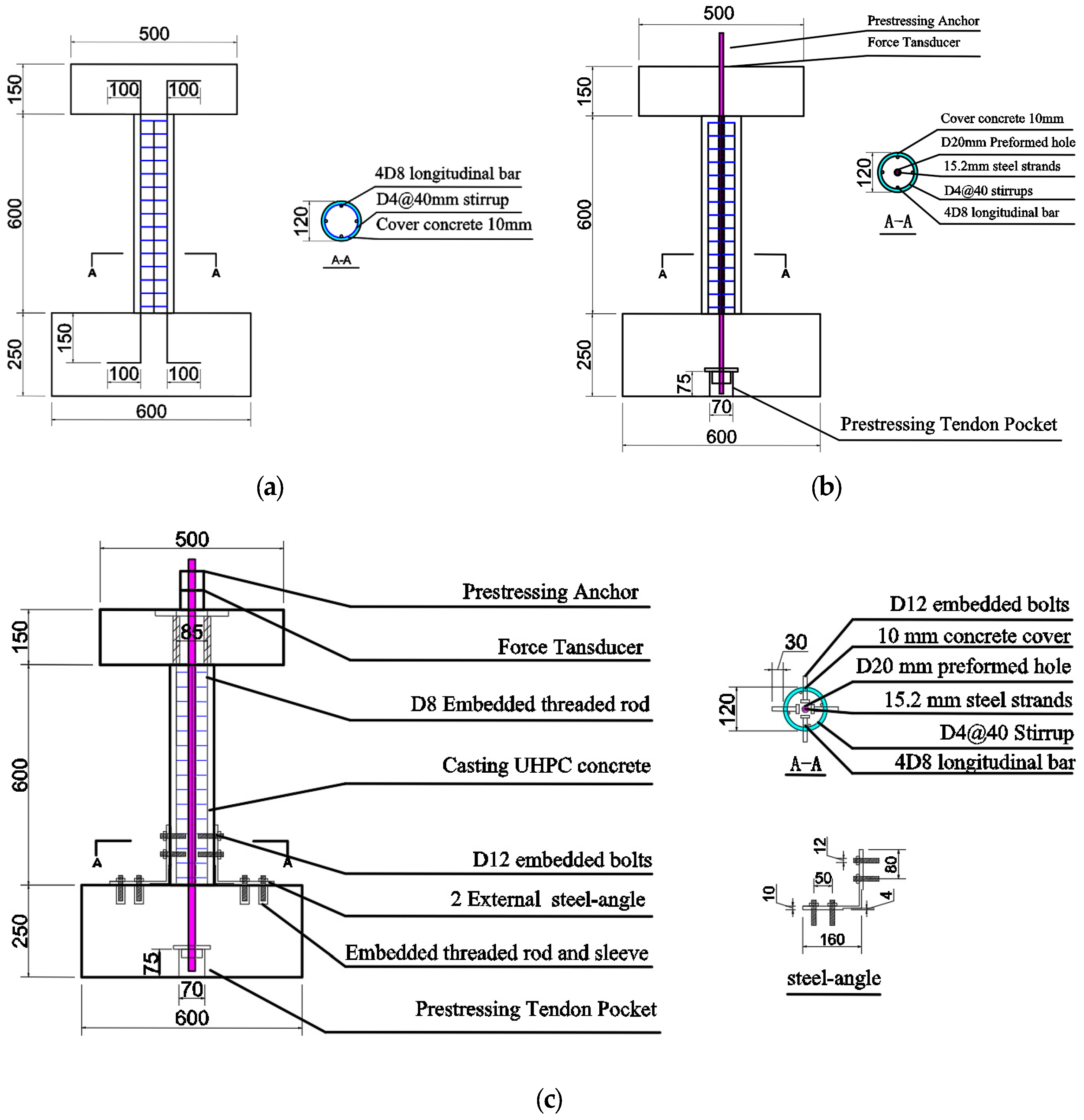
In this study, three specimens were tested: a conventional cast-in-place reinforced concrete (RC) column, a traditional precast concrete pier constructed with normal-strength concrete (S1), and a seismic-resilient precast pier (S2). Table 1 summarizes the key specimen details. Each specimen comprised a single column segment, a foundation block, and a top loading block. For the RC specimen, as illustrated in Figure 1a, the column had a diameter of 120 mm and a height of 600 mm. The foundation block measured 600 mm × 600 mm × 250 mm (L × W × H), and the top loading block measured 500 mm × 500 mm × 150 mm. The total pier height was 1000 mm.
Specimen S1, as illustrated in Figure 1b, differs from specimen RC primarily by the incorporation of a 20 mm diameter central hole through the foundation, column, and loading block to accommodate a prestressing tendon. An anchorage device was installed atop the loading block to secure the tendon, along with a load cell for force monitoring. Additionally, a recess measuring 70 mm × 70 mm × 75 mm (L × W × H) was provided at the bottom center of the foundation base to anchor the lower end of the tendon.
Specimen S2, illustrated in Figure 1c, is similar to column S1 in dimensions except for two differences. One is that this column adopted UHPC instead of normal-strength concrete. The second difference is that external ED steel angles were installed between the footing and the column to improve the energy dissipation capacity of the column. To connect the steel angles, threaded bars and sleeves were embedded and cast together with the concrete of the column and footing, respectively. Then the steel angles were tied to the column and footing with high-strength nuts. This structural system effectively combines self-centering capacity with enhanced energy dissipation, providing superior seismic resilience.
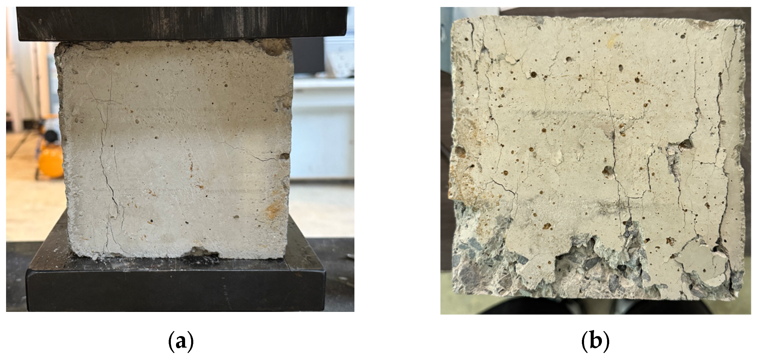
The specimens were cast using ready-mixed concrete with a design compressive strength of 30 MPa, and the measured cube compressive strength on the test day was 38.91 MPa (As shown in Figure 2). For the UHPC used in the column of S2, the measured compressive strength was 135.6 MPa. The mechanical properties of all materials are summarized in Table 2. The mechanical properties of the steel tendons in Table 2 are all obtained from the product technical specifications provided by their supplier. The mechanical property parameters of the longitudinal bars are all obtained from the tensile tests conducted in the lab. The tests were strictly carried out in accordance with Metallic Materials—Tensile Testing (GB/T 228.1-2021) [35]. A total of 3 groups of standard specimens were prepared, and loading was completed using a universal testing machine.
In this study, the target post-tensioning force was set to 70 kN, with this design grounded in findings from prior research on precast columns. As established in previous studies [15,27,36], the typical dead load of precast columns accounts for approximately 10% of their axial loading capacity, quantified as 0.1fcAg (where fc denotes the concrete compressive strength and Ag represents the gross cross-sectional area of the column). To ensure precast columns achieve both favorable self-centering capacity and ductility, the ratio of prestressing force to the column’s axial capacity is generally constrained to less than 0.2. Notably, the prestressing force tends to increase when the column undergoes rocking under lateral loading. Consequently, as recommended in [15,27,36], the initial prestressing stress level of the tendon should be limited to approximately 30% of the tendon’s ultimate strength. Based on this principle, the quantity of prestressing tendons can be determined by the required prestressing force and the preset initial prestressing stress. In the present study, the target post-tensioning force was set to 70 kN, corresponding to 0.16fcAg; the initial prestressing stress of the tendon was approximately 0.27 times its ultimate strength. Both parameters fall within the aforementioned recommended limits, verifying the rationality of the prestressing design.

2.2. Fabrication of Specimens

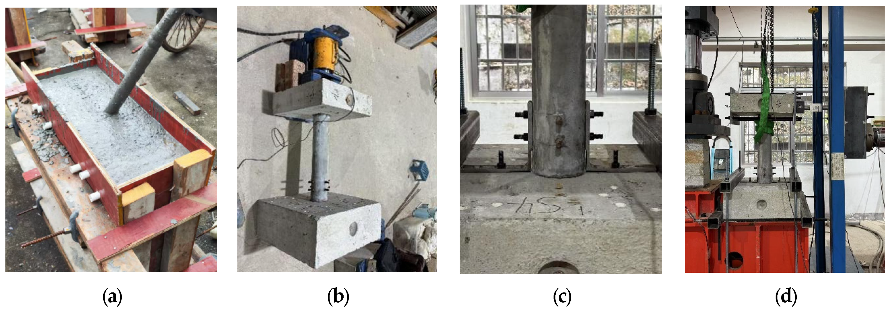
All components of the cast-in-place and precast piers, including the foundation, column, and loading block, were prefabricated in a factory and subsequently delivered to the lab. Figure 3 shows the construction sequence of representative specimens. Figure 3a shows the concrete casting. After concrete curing, the installation began by placing the foundation laterally on the ground. A tendon was then inserted through the central duct of the column to connect it with the loading block, thereby completing the column assembly. As shown in Figure 3b, post-tensioning was subsequently applied using a hydraulic jack mounted on top of the loading block. For specimens S1 and S2, the applied post-tensioning forces were 70.64 kN and 65.29 kN, respectively. The final step involved the installation of external angle steel components for S2, with the details illustrated in Figure 3c. Lastly, the specimen was lifted and installed on a loading frame, which is shown in Figure 3d.

3. Experimental Setup

3.1. Installation of Specimens

To evaluate the seismic performance of precast bridge piers, cyclic loading tests were conducted. The experimental setup is depicted in Figure 4a, and the actual test configuration is shown in Figure 4b. The loading system comprised a horizontal reaction frame and a footing fixing beam. The specimen footing was anchored to the footing fixing beam using vertical and transverse steel beams and high-strength bolts. Due to the limitation of the arrangement of the actuator, a force transfer beam was installed on the actuator. An S-type loading cell was installed between the specimen and the force transfer beam. Two hinges were also installed to avoid a potential bending moment applied on top of the column. The lateral loading point is located 660 mm above the top surface of the foundation. The lateral displacement of the column at the loading point was measured using a linear variable displacement transducer (LVDT), and both loading force and displacement were recorded in real time using an HBM data acquisition system.

3.2. Loading Protocol

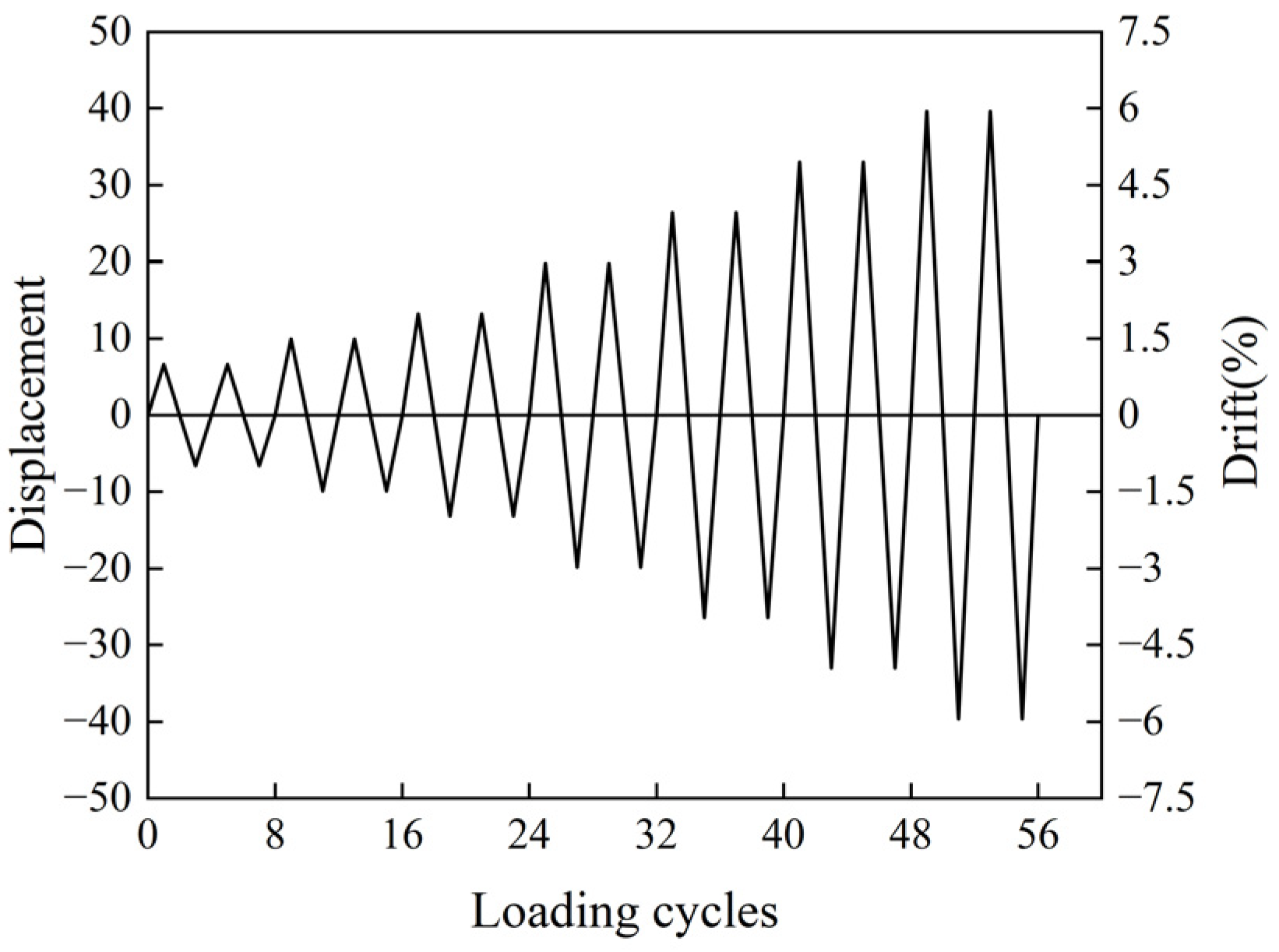
All specimens were subjected to the same lateral cyclic loading. The loading sequence consisted of incremental lateral drift ratios of 0.5%, 1%, 1.5%, 2%, 3%, 4%, 5%, and 6% [8]. Here, the drift ratio is defined as D/H, where D is the lateral displacement at the loading point, and H is the distance from the top surface of the foundation to the loading point (660 mm in this test). Each drift level was applied in two full loading cycles. The cyclic loading protocol adopted in this study is illustrated in Figure 5.

4. Test Results

4.1. Damage Observations

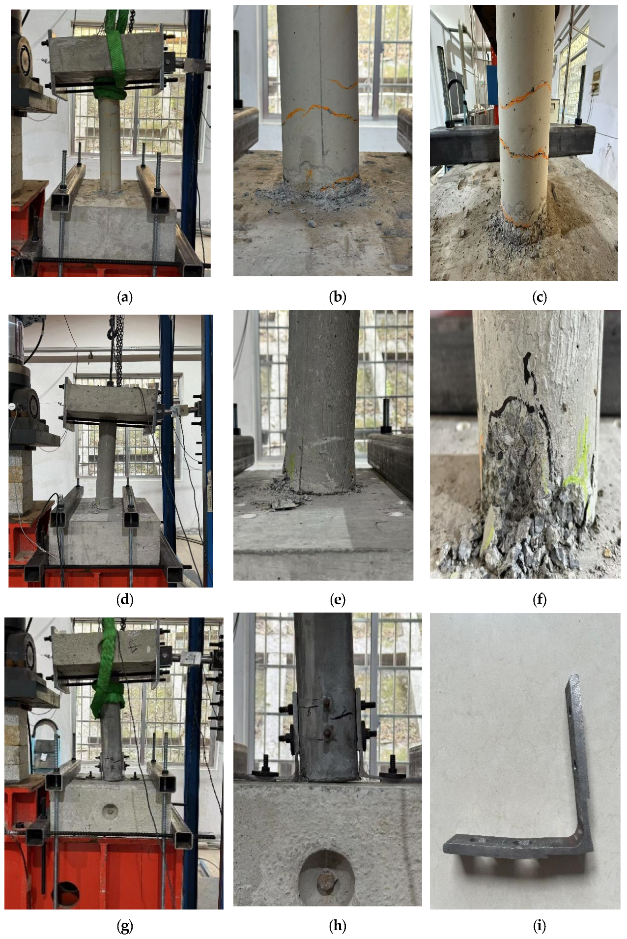
Figure 6 illustrates the damage states of specimens RC, S1, and S2 at a 6% drift ratio.
For the RC specimen, initial minor flexural cracks were observed at the bottom segment when the drift ratio reached 1%. These cracks exhibited horizontal orientation and progressively extended vertically along the segment height as the drift increased. At a 3% drift ratio, the crack openings became more pronounced, with additional cracks propagating upward along the height of the column. When the drift reached 6%, vertical cracks emerged at the interface between the bottom segment and the footing, accompanied by concrete spalling and crushing in the lower region. Figure 6a presents the global deformation pattern of the RC column. while Figure 6b,c show front and right views of the damage, respectively. Evidently, cracking, spalling, and crushing were concentrated in the bottom segment, with the spalled region extending approximately 0–15 mm above the top surface of the footing.
For specimen S1, cracking initiated at the bottom of the column when the drift ratio reached 1%, with a pattern similar to the RC specimen. As the drift increased, these cracks extended laterally across the surface and new cracks appeared progressively along the column height. At 5% drift, the first vertical crack emerged at the bottom segment, accompanied by localized concrete crushing and spalling. As drift continued to increase, the severity of crushing and spalling became more pronounced. At a drift ratio of 6%, significant surface spalling occurred, exposing sections of transverse reinforcement. Figure 6d displays the global damage state at 6% drift, while Figure 6e,f illustrate severe crushing and spalling at the column base, extending approximately 0–200 mm above the footing surface.
For specimen S2, no visible cracks were observed at low drift levels. At a 3% drift ratio, slight buckling of the external angle steel at the column base was first recorded, along with the appearance of minor surface cracking. When the drift reached 4%, a small separation gap developed at the lower right corner between the segment and foundation, with an increase in the number of visible surface cracks. As the drift ratio further increased, the buckling deformation of the angle steels on both sides became more pronounced, and the segment–foundation interface separation widened. As shown in Figure 6g, when the drift ratio increased to 6%, a gap of approximately 2 mm developed between the lower right corner of the segment and the foundation, and the number of visible cracks on the column surface increased (Figure 6h,i). Upon completion of the test, the removed angle steel components exhibited significant deformation, indicating substantial plastic engagement within the designated energy dissipation region on the steel angle.

4.2. Hysteretic Curve

Figure 7 illustrates the hysteresis curves of specimens RC, S1, and S2 at a 6% drift ratio. For specimen RC (Figure 7a), the hysteresis loops enclosed relatively small areas prior to 3% drift, with lateral load increasing approximately linearly. Beyond this point, strength development became nonlinear, and the loop areas expanded, indicating progressive plastic deformation. It should be mentioned that the plastic deformation of the RC column includes the concrete damage and the steel rebar yielding, which are both difficult to repair. While the cast-in-place column exhibited considerable energy dissipation capacity, it also showed large residual displacements and limited self-centering capability. This further increases the difficulty of post-earthquake retrofitting activities.
For specimen S1 (Figure 7b), the hysteresis loops enclosed limited areas when the drift ratio was below 1%, and lateral strength increased approximately linearly with drift. As drift increased, strength development became nonlinear, and the loop areas expanded notably, indicating progressive plastic deformation. Compared with the cast-in-place column, the precast column had smaller residual displacements, demonstrating superior self-centering capability. The unbonded post-tensioned tendons effectively reduced residual displacements and enhanced self-centering ability, contributing to improved post-earthquake reparability and seismic resilience.
Figure 7c presents the hysteresis curves of specimen S2. Compared to specimen S1, the S2 column exhibited more stable hysteretic behavior and superior ductility. The residual displacements remained minimal even at a drift ratio of 6%. Due to the implementation of external angle steel, the hysteretic curves enclose large areas, indicating excellent energy dissipation capacity under large deformations. Furthermore, the stiffness degradation between successive cycles was relatively mild, and no significant strength degradation was found even at 6% drift. In summary, the hysteretic behavior of specimen S2 demonstrates excellent energy dissipation, stable strength retention, and self-centering capability, thereby validating the effectiveness of the proposed seismic-resilient design.

4.3. Skeleton Curve

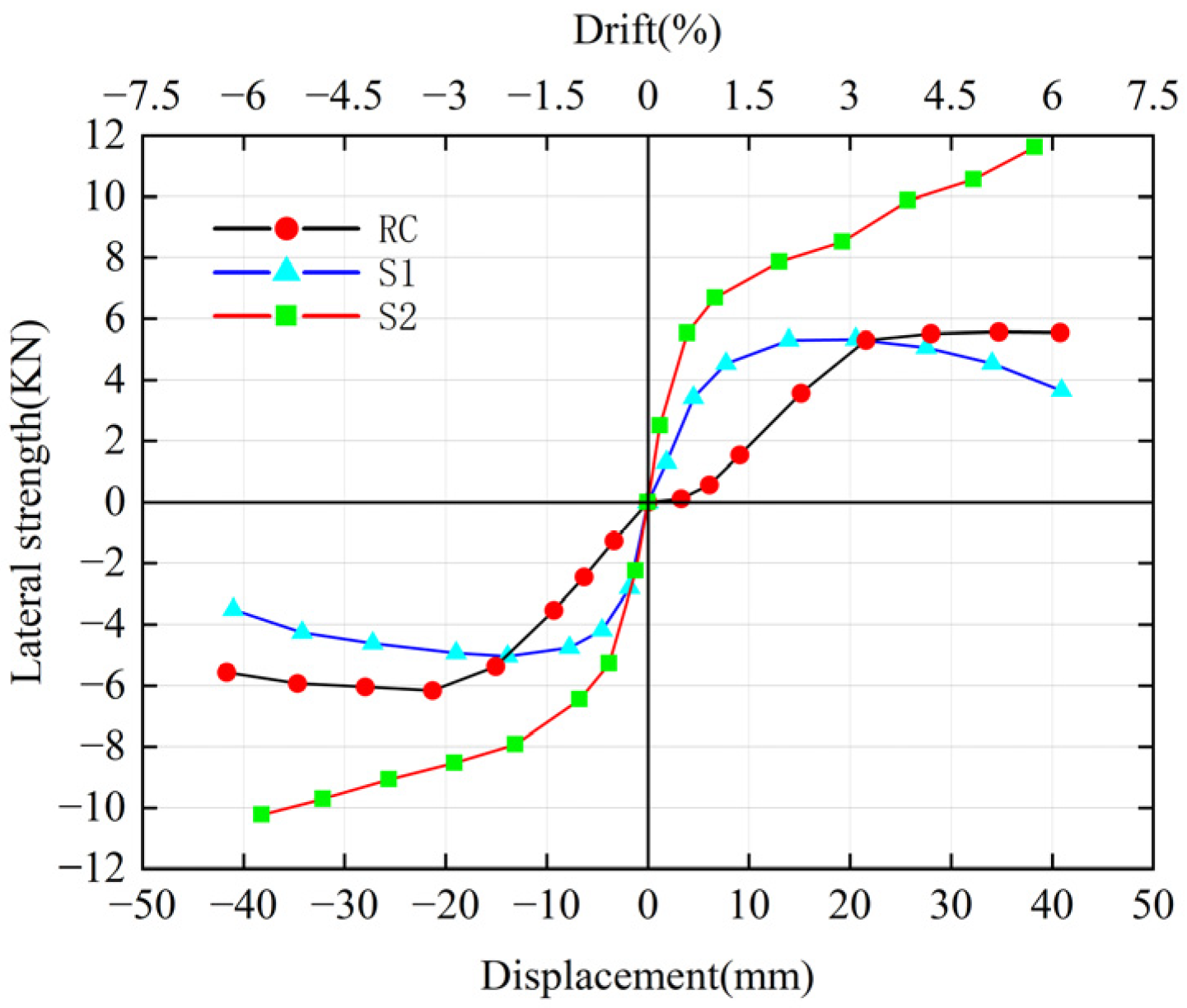
Figure 8 presents the skeleton curves of the three specimens. For the RC specimen, the peak lateral load capacities were 5.57 kN (positive) and 6.01 kN (negative) at 5.3% and −3.2% drift, respectively, decreasing to 5.52 kN and 5.56 kN at 6% drift, respectively, corresponding to strength degradation rates of 1.9% and 8%. The post-peak stiffness reduction was insignificant, particularly in the positive direction. Meanwhile, through calculations, we obtained that the ductility coefficient of the RC specimen is 1.88 [37], and its initial stiffness is 0.2 kN/mm, indicating good ductility and stable load-bearing capacity over a broad deformation range. It should be noted that the stiffness of the column in the positive displacement direction was small before 1.5% drift. This could be attributed to the damage caused by the delivery stage prior to the test.
In contrast, the S1 specimen exhibited lower peak strengths (5.31 kN and 5.04 kN at 2.1% drift) and more pronounced post-peak degradation (decreased to 3.65 kN and 3.51 kN at 6% drift), especially in the negative direction. Through calculations, we obtained that the ductility coefficient of Specimen S1 is 4.36 and its initial stiffness is 1.25 kN/mm. This indicates that although Specimen S1 has relatively low peak strength and a limited load-bearing capacity upper limit, with significant post-peak load-bearing capacity degradation (especially in the negative direction) and weak damage resistance under large deformations, it exhibits good ductility and can still maintain a certain degree of deformation capacity during the degradation process.
The S2 specimen exhibited a notably higher peak load capacity. The peak load is 11.62 kN. Through calculations, we obtained that the ductility coefficient of Specimen S2 is 5.21 and its initial stiffness is 1.9 kN/mm, which indicates that Specimen S2 has a stable structure and excellent ductility. It is primarily attributed to the superior mechanical properties of UHPC and the application of steel angles. The use of UHPC significantly enhanced the localized bearing capacity of the concrete and maintained the integrity of the column section as compared to column S1 with conventional concrete, which increased the strength of column S2. In addition, the external angle steel further improved the overall load-bearing performance of the structure. No strength degradation was observed, which further confirms its excellent seismic performance and deformation recovery capability.

4.4. Residual Displacement

Residual displacement is a key indicator for evaluating the post-earthquake reparability of structural systems. Excessive residual drift can result in misalignment of structural elements, increased difficulty in repositioning, and significantly higher repair costs. In practical engineering, reducing the residual displacement of bridge piers is therefore particularly important. A smaller residual displacement can effectively lower the difficulty of post-earthquake repair, as well as save repair costs and time. Figure 9 presents the residual displacements of the specimens at a drift ratio of 6%. The cast-in-place reinforced concrete (RC) column exhibited the largest residual displacement (13.33 mm), indicating poor recentering capacity and a high tendency for permanent deformation under seismic loading. In contrast, the precast columns S1 and S2 showed significantly reduced residual displacements, measured at 5.53 mm and 1.03 mm, corresponding to 0.88% and 0.15% drift ratios, respectively. The enhanced performance of specimen S1 is primarily attributed to the restoring force provided by the unbonded post-tensioned tendons, which is a critical feature in minimizing residual displacement in seismic design. For specimen S2, the residual drift was further reduced, owing not only to the inclusion of unbonded post-tensioning tendons but also to the presence of the UHPC column, which helped reduce the damage to the column. Therefore, it can be found that the proposed seismic resilient column S2 exhibited limited damage and small residual displacement, both of which are beneficial for post-earthquake repair. As specified in Highway Bridge Seismic Design Code (JTG/T 2231-01-2020) [38] and FEMA 273, the requirements for residual displacement should be ≤0.5% to maintain the ‘Life Safe’ status. Combined with the data of this study, after loading at a peak drift ratio of 6%, the residual drift ratio of Specimen S2 is only 0.15%, which is significantly lower than the threshold specified in the codes. This directly demonstrates its engineering advantage in “reducing the difficulty of post-earthquake repair”. With these characteristics, the retrofitting cost and time can be effectively reduced.

4.5. Cumulative Energy Dissipation

Figure 10 presents the cumulative energy dissipation and equivalent viscous damping of each specimen under cyclic loading. As the drift ratio increased, plastic deformation gradually developed, enhancing the energy dissipation capacity of the structures. In the initial loading stages, all specimens exhibited relatively low energy dissipation due to the limited development of nonlinear responses. However, with increasing drift, specimen S2 demonstrated the highest cumulative energy dissipation, followed by the cast-in-place RC column, while specimen S1 consistently exhibited the lowest dissipation performance. At 6% drift, the cumulative ED of RC, S1 and S2 were 950.02 kN·mm, 615.87 kN·mm, 1602.71 kN·mm, respectively. As the drift ratio increases, the difference in equivalent viscous damping ratios among the three specimens becomes more significant. When the drift ratio reaches 6%, the equivalent viscous damping coefficient of RC is 14.15%, that of S1 is 9.84%, and that of S2 is 8.59%. The superior ED of the RC column compared to S1 is primarily attributed to its monolithic cast-in-place construction, which ensures structural continuity and eliminates potential weaknesses at joints. This enables more effective plastic deformation in the continuous rebars and thus more energy absorption under seismic loading. In contrast, S1 was constructed using precast elements connected through an unbonded tendon. Under repeated loading, this assembly is more prone to joint rocking, leading to reduced energy dissipation. Specimen S2, by contrast, adopted a distinctly different structural configuration. The external steel angles significantly improved the energy dissipation capacity of S2. The external design also made it easy to replace after strong earthquakes.

5. Discussion

This study investigates the seismic performance of a novel ultra-high-performance concrete (UHPC) precast pier (S2), which integrates external steel-angle energy-dissipating components and unbonded post-tensioned tendons. The performance of this pier was compared with that of a cast-in-place reinforced concrete (RC) pier and a conventional precast concrete pier (S1). This section focuses on interpreting the key experimental results (Table 3 summarizes the experimental data), as well as clarifying the innovative value and limitations of the proposed pier system.
Specimen S2 exhibited excellent damage control capability, with minimal cracking in the column and plastic deformation concentrated in the steel angles. This advantage stems from the high compressive strength (135.6 MPa) and crack resistance of UHPC, which effectively mitigates concrete crushing at the rocking interface. By combining UHPC with external energy-dissipating components, this study further reduces the residual damage of the structure—in the tests, S2 only developed slight surface cracks without obvious concrete spalling or crushing. In contrast, both the RC pier and Specimen S1 suffered severe spalling at the base (with the spalling range of S1 reaching 0–200 mm), which fully indicates that monolithic cast-in-place or conventional precast structures have significant shortcomings in targeted damage control and cannot achieve the design goal of “damage concentrated in replaceable components and minimal damage to the main structure” as S2 does. In terms of energy dissipation capacity, the cumulative energy dissipation of S2 was significantly enhanced, reaching 1602.71 kN·mm at a 6% drift ratio. Moreover, the external steel angles are connected to the column and foundation via bolts, allowing direct disassembly and replacement after an earthquake. In contrast, although Specimen S1 possesses a certain self-centering capacity relying on unbonded post-tensioned tendons, its cumulative energy dissipation is only 615.71 kN·mm, and it lacks sufficient seismic resilience due to the absence of dedicated energy-dissipating components. Internal energy-dissipating bars commonly used in existing studies require concrete breaking for replacement after an earthquake, resulting in great repair difficulty. However, the external steel angle design of S2 properly solves this problem of “difficulty in repair after damage”. Regarding residual displacement, the residual displacement of S2 is only 1.03 mm, which is much smaller than that of S1 (5.53 mm) and the RC pier (13.33 mm). This result highlights the synergistic effect of UHPC and unbonded post-tensioned tendons—UHPC enhances the integrity of the column and reduces local damage, while the post-tensioned tendons provide a stable restoring force. Together, they ensure the excellent self-centering capacity of S2.
Compared with the RC pier and Specimen S1 in the document, the innovative value of the S2 pier system is mainly reflected in three aspects: Firstly, Traditional RC piers rely on the plastic deformation of the main structure for energy dissipation, which easily leads to irreparable damage. Although Specimen S1 reduces residual displacement through unbonded post-tensioned tendons, its energy dissipation capacity is weak. In contrast, the S2 pier uses UHPC to protect the main body of the column and external steel angles to undertake energy dissipation. This design not only avoids damage to the main structure but also achieves efficient energy dissipation through the plastic deformation of the steel angles—addressing the inherent trade-off between damage control and energy dissipation in RC piers and Specimen S1. Secondly, the external steel angles of S2 adopt a modular design and are connected through the “pre-embedded threaded bars and high-strength nuts” method. Compared with traditional external energy-dissipating components, for example, the reduced-steel-plate (RSP) devices proposed by Chou et al. [7], are connected to the main body of the pier via welding. After an earthquake, the damaged steel plates need to be removed by cutting, and the replacement process is likely to cause secondary damage to the pier’s concrete. Although the buckling-restrained braces (BRBs) studied by Marriott et al. [31], adopt a modular design, they require special connectors for disassembly, resulting in a complicated replacement procedure. However, for Specimen S2, after an earthquake, the damaged steel angles can be replaced directly without destroying the column or foundation. Compared with the repair process of internal energy-dissipating (ED) bars mentioned in the Introduction of this document, this design significantly shortens the repair time and reduces the repair costs. Thirdly, UHPC not only enhances the crack resistance and compressive performance of the column but also improves the effective transmission of the prestressing force of the post-tensioned tendons—preventing prestress loss caused by concrete cracking. This ensures the post-tensioned tendons maintain a stable self-centering force throughout the loading process. Such a synergistic effect is absent in both RC piers (without UHPC reinforcement) and Specimen S1 (without UHPC protection), and it is also the core reason why the residual displacement of S2 (only 1.03 mm at 6% drift ratio) is much smaller than that of the two counterparts.
This study has certain limitations: Firstly, the specimens were small-scale models, which may underestimate the impact of size effects on structural performance. For instance, the bond behavior between UHPC and steel bars, as well as the uniformity of plastic deformation of external steel angles in actual engineering, may differ from those observed in small-scale specimens. Secondly, the quasi-static cyclic loading protocol was adopted, which fails to fully simulate the dynamic response under earthquake action. Consequently, it cannot reflect the strain rate effect of UHPC or the fatigue performance of steel angles under repeated dynamic loads.
Future research should address the aforementioned limitations in the context of this study: Firstly, adopt shake table tests or dynamic cyclic loading protocols to explore the dynamic response law of the S2 pier; Secondly, conduct durability tests on the external steel angles to ensure their reliability during the long-term service of bridges, thereby further verifying the practical engineering applicability of the proposed pier system.

6. Conclusions

This study proposed a precast concrete bridge pier system aimed at enhancing the seismic resilience and post-earthquake reparability of bridges. The seismic performance of the column was evaluated through a cyclic loading test. From the test observations, the effectiveness and feasibility of the proposed seismic-resilient design were validated. Based on the results, some conclusions are summarized as follows:
(1)
The proposed precast bridge pier (S2), which integrates ultra-high-performance concrete (UHPC) and external replaceable steel angles, demonstrated higher resistance to localized concrete damage. The steel angles experienced obvious plastic deformation, which contributed to the ED of the column. The external arrangement facilitates an easy and fast replacement after strong earthquakes.
(2)
Compared to both the S1 and cast-in-place RC specimens, the S2 pier achieved a higher peak lateral strength (up to 11.62 kN) and no strength degradation due to the high compressive strength and fracture resistance of UHPC. The measured compressive strength of the UHPC used in Specimen S2 reaches 135.6 MPa, which can effectively inhibit concrete cracking and crushing at the column–foundation rocking interface. Even at a drift ratio of 6%, only slight surface cracks appear on S2, with no obvious concrete spalling or core damage. In contrast, the RC specimen exhibits concentrated cracking, spalling, and crushing in the range of 0–15 mm at the bottom, while the spalling range at the column base of Specimen S1 even extends to 0–200 mm. These results fully demonstrate the protective effect of UHPC on the main structure.
(3)
The precast columns S1 and S2 with unbonded post-tensioned tendon demonstrated excellent self-centering capability under cyclic loading. The use of UHPC further reduced the column damage and thus the residual displacement. The synergistic effect of the two compensates for the defect of Specimen S1, which relies solely on post-tensioned tendons but still has relatively high residual displacement due to the damage of normal-strength concrete. This achieves the dual guarantee of “stable restoring force + low damage to the main structure”. At 6% drift, the residual displacement of S2 was limited to only 1.03 mm, which is significantly smaller than that of the cast-in-place RC column (13.33 mm) and the conventional precast pier S1 (5.53 mm).
(4)
Experimental results confirm that the S2 pier demonstrated superior energy dissipation capacity. The cumulative ED of S2 at 6% drift was 1602.71 kN·mm, which is higher than those of RC (950.02 kN·mm) and S1 (615.87 kN·mm). The use of steel angles effectively improved the ED of the precast pier; it also ensured quick post-earthquake replaceability.
In conclusion, a precast pier can significantly improve construction efficiency. The proposed precast concrete bridge pier S2 outperformed both the RC and S1 piers in terms of strength retention, hysteretic stability, and residual drift control. The modular design facilitates easier transportation and installation, while the detachable energy-dissipating components enable efficient post-earthquake repair and maintenance. These findings highlight the potential of the proposed configuration as a practical and resilient solution for precast bridge systems in high seismic regions.

Author Contributions

Formal analysis, Y.P. and K.X.; Investigation, Y.P., P.Y. and K.X.; Data curation, P.Y.; Writing—original draft, Y.P.; Writing—review & editing, C.L.; Supervision, C.L. All authors have read and agreed to the published version of the manuscript.

Funding

Natural Science Foundation of Hunan Province (2023JJ40727) and National Natural Science Foundation of China (52008407).

Data Availability Statement

The original contributions presented in this study are included in the article. Further inquiries can be directed to the corresponding author.

Conflicts of Interest

The authors declare no conflict of interest.

References

  1. Ou, Y.-C.; Wang, P.-H.; Tsai, M.-S.; Chang, K.-C.; Lee, G.C. Large-scale experimental study of precast segmental unbonded posttensioned concrete bridge columns for seismic regions. J. Struct. Eng. 2010, 136, 255–264. [Google Scholar] [CrossRef]
  2. Cogurcu, M.T.; Uzun, M. Experimental investigation of a new precast column-foundation connection under cyclic loading. J. Build. Eng. 2022, 50, 104245. [Google Scholar] [CrossRef]
  3. Bi, K.; Li, C.; Hao, H. State-of-the-art review of the seismic performance of precast segmental columns. Adv. Bridge Eng. 2022, 3, 7. [Google Scholar] [CrossRef]
  4. Ou, Y.-C.; Lau, J.V.J.; Li, J.-Y.; Havlasek, P.; Bittnar, Z. Cyclic behavior of reinforced concrete columns with five-spiral reinforcement. J. Build. Eng. 2022, 61, 105245. [Google Scholar] [CrossRef]
  5. Li, C.; Bi, K.; Hao, H.; Zhang, X.; Van Tin, D. Cyclic test and numerical study of precast segmental concrete columns with BFRP and TEED. Bull. Earthq. Eng. 2019, 17, 3475–3494. [Google Scholar] [CrossRef]
  6. Billington, S.L.; Yoon, J.K. Cyclic response of unbonded posttensioned precast columns with ductile fiber-reinforced concrete. J. Bridge Eng. 2004, 9, 353–363. [Google Scholar] [CrossRef]
  7. Chou, C.C.; Chen, Y.C. Cyclic tests of post-tensioned precast CFT segmental bridge columns with unbonded strands. Earthq. Eng. Struct. Dyn. 2006, 35, 159–175. [Google Scholar] [CrossRef]
  8. Ou, Y.C.; Tsai, M.S.; Chang, K.C.; Lee, G.C. Cyclic behavior of precast segmental concrete bridge columns with high performance or conventional steel reinforcing bars as energy dissipation bars. Earthq. Eng. Struct. Dyn. 2010, 39, 1181–1198. [Google Scholar] [CrossRef]
  9. Li, C.; Bi, K.; Hao, H. Seismic performances of precast segmental column under bidirectional earthquake motions: Shake table test and numerical evaluation. Eng. Struct. 2019, 187, 314–328. [Google Scholar] [CrossRef]
  10. Cai, Z.-K.; Yuan, W.; Wang, Z.; Smith, S.T. Seismic behavior of precast segmental bridge columns reinforced with hybrid FRP-steel bars. Eng. Struct. 2021, 228, 111484. [Google Scholar] [CrossRef]
  11. Li, C.; Bi, K.; Hao, H.; Zuo, H.; Do, T.V. Shake-table tests of BFRP-reinforced geopolymer concrete segmental columns. Bull. Earthq. Eng. 2022, 20, 7287–7311. [Google Scholar] [CrossRef]
  12. Salehi, M.; Valigura, J.; Sideris, P.; Liel, A.B. Experimental assessment of second-generation hybrid sliding-rocking bridge columns under reversed lateral loading for free and fixed end rotation conditions. J. Bridge Eng. 2021, 26, 04021071. [Google Scholar] [CrossRef]
  13. Li, C.; Xiang, Y.; Bi, K.; Cai, C. Seismic performance of precast CFDST segmental column with hybrid energy dissipation devices. J. Constr. Steel Res. 2022, 197, 107455. [Google Scholar] [CrossRef]
  14. Cai, Z.-K.; Zhou, Z.; Wang, Z. Influencing factors of residual drifts of precast segmental bridge columns with energy dissipation bars. Adv. Struct. Eng. 2019, 22, 126–140. [Google Scholar] [CrossRef]
  15. Elgawady, M.; Booker, A.J.; Dawood, H.M. Seismic behavior of posttensioned concrete-filled fiber tubes. J. Compos. Constr. 2010, 14, 616–628. [Google Scholar] [CrossRef]
  16. Wang, J.; Wang, Z.; Tang, Y.; Liu, T.; Zhang, J. Cyclic loading test of self-centering precast segmental unbonded posttensioned UHPFRC bridge columns. Bull. Earthq. Eng. 2018, 16, 5227–5255. [Google Scholar] [CrossRef]
  17. Dangol, I.; Pantelides, C.P. Resilient posttensioned bridge bent with buckling restrained brace. J. Bridge Eng. 2022, 27, 04021107. [Google Scholar] [CrossRef]
  18. Varela, S.; Saiidi, M. Resilient deconstructible columns for accelerated bridge construction in seismically active areas. J. Intell. Mater. Syst. Struct. 2017, 28, 1751–1774. [Google Scholar] [CrossRef]
  19. Nikoukalam, M.; Sideris, P. Resilient bridge rocking columns with polyurethane damage-resistant end segments and replaceable energy-dissipating links. J. Bridge Eng. 2017, 22, 04017064. [Google Scholar] [CrossRef]
  20. Kawashima, K.; MacRae, G.A.; Hoshikuma, J.I.; Nagaya, K. Residual displacement response spectrum. J. Struct. Eng. 1998, 124, 523–530. [Google Scholar] [CrossRef]
  21. Saeidzadeh, M.; Chenaghlou, M.R.; Hamed, A.A. Mechanical model and seismic performance of frames with a self-centring connection. Proc. Inst. Civ. Eng.-Struct. Build. 2024, 177, 633–648. [Google Scholar] [CrossRef]
  22. Saeidzadeh, M.; Chenaghlou, M.R.; Hamed, A.A. Experimental and numerical study on the performance of a novel self-centering beam-column connection equipped with friction dampers. J. Build. Eng. 2022, 52, 104338. [Google Scholar] [CrossRef]
  23. Saeidzadeh, M.; Bafandeh Nobari, H.; Akbari Hamed, A. Numerical parametric study on structural performance and design of self-centering eccentrically braced frames with novel SC-PC-FD connections. Iran. J. Sci. Technol. Trans. Civ. Eng. 2025, 1–27. [Google Scholar] [CrossRef]
  24. Akbarnezhad, M.; Salehi, M.; DesRoches, R. Seismic design and numerical assessment of shape memory alloy-restrained rocking precast concrete bridge columns. Adv. Struct. Eng. 2022, 25, 2803–2829. [Google Scholar] [CrossRef]
  25. Xia, Z.; Ge, J.; Lin, Y.; Qiu, F. Shake table study on precast segmental concrete double-column piers. Earthq. Eng. Eng. Vibr. 2020, 19, 705–723. [Google Scholar]
  26. Dawood, H.; Elgawady, M.; Hewes, J. Factors affecting the seismic behavior of segmental precast bridge columns. Front. Struct. Civ. Eng. 2014, 8, 388–398. [Google Scholar] [CrossRef]
  27. Hewes, J.T. Seismic Design and Performance of Precast Concrete Segmental Bridge Columns; University of California, San Diego: San Diego, CA, USA, 2002. [Google Scholar]
  28. Li, C.; Peng, Y.; Yang, P.; Zhou, H.; Wang, N. Behavior of a Precast Bridge Pier with Basalt Fiber-Reinforced Polymer (BFRP)-Strengthened Segments under Seismic Loading. Polymers 2024, 16, 2018. [Google Scholar] [CrossRef]
  29. Li, C.; Xiang, Y.; Cai, C. Performance of a seismic-resilient precast segmental column with UHPC segments and CFRP tendon. Eng. Struct. 2023, 282, 115833. [Google Scholar] [CrossRef]
  30. Ma, C.; Zheng, X.; Zhu, Z.; Zhou, M. Seismic behavior of precast columns with unbonded prestressed tendons and energy-dissipating bars: Physical and numerical investigations. Sci. Rep. 2023, 13, 21983. [Google Scholar] [CrossRef]
  31. Marriott, D.; Pampanin, S.; Palermo, A. Biaxial testing of unbonded post-tensioned rocking bridge piers with external replacable dissipaters. Earthq. Eng. Struct. Dyn. 2011, 40, 1723–1741. [Google Scholar] [CrossRef]
  32. Li, C.; Xiang, Y.; Bi, K.; Hao, H.; Li, H.; Cai, C. Seismic performance of a GFRP–concrete–steel hollow section segmental column with SMA bars and replaceable ED devices. Thin-Walled Struct. 2023, 191, 111018. [Google Scholar] [CrossRef]
  33. Li, C.; Xiang, Y.; He, X.; Yang, P.; Zhou, H.; Cai, C. Investigation of the seismic performance of a precast CFDST column with internal SMA and external energy dissipating devices. Structures 2024, 61, 106000. [Google Scholar] [CrossRef]
  34. Li, C.; Yang, P.; Peng, Y. Development and experimental study of a two-stage self-centering friction damper. Structures 2025, 80, 109821. [Google Scholar] [CrossRef]
  35. GB/T 228.1-2021; Metallic Materials—Tensile Testing—Part 1: Method of Test at room Temperature. Standardization Administration of the People’s Republic of China: Beijing, China, 2021.
  36. Cai, Z.-K.; Wang, Z.; Yang, T. Experimental testing and modeling of precast segmental bridge columns with hybrid normal-and high-strength steel rebars. Constr. Build. Mater. 2018, 166, 945–955. [Google Scholar] [CrossRef]
  37. Council BSS. Prestandard and Commentary for the Seismic Rehabilitation of Buildings; Report FEMA-356; Council BSS: Washington, DC, USA, 2000.
  38. JTG/T 2231-01-2020; Specifications for Seismic Design of Highway Bridges. Ministry of Transport of the People’s Republic of China: Beijing, China, 2020.
Figure 1. Design details of the bridge piers: (a) RC; (b) S1; (c) S2.
Buildings 15 03272 g001
Figure 2. Cube compressive strength test: (a) experimental procedure; (b) final failure.
Buildings 15 03272 g002
Figure 3. Construction procedures of specimens: (a) concrete casting; (b) post-tensioning procedure; (c) Installation of external steel angle in specimen S2; (d) specimen installation.
Buildings 15 03272 g003
Figure 4. Test setup: (a) schematic diagram; (b) photograph of the test system.
Buildings 15 03272 g004
Figure 5. Cyclic Loading Protocol.
Buildings 15 03272 g005
Figure 6. Post-test damage observations of the specimens: (a) the global deformation pattern of the RC; (b) the front views of the RC; (c) the right view of the RC; (d) the global deformation pattern of the S1; (e) the front view of the S1; (f) the right view of the S1; (g) the global deformation pattern of the S2; (h) the front view of the S2; (i) the view of the Yielded steel-angle.
Buildings 15 03272 g006
Figure 7. Hysteretic curves: (a) RC; (b) S1; (c) S2.
Buildings 15 03272 g007
Figure 8. Skeleton Curves.
Buildings 15 03272 g008
Figure 9. Residual Displacement.
Buildings 15 03272 g009
Figure 10. (a) Cumulative Energy Dissipation; (b) Equivalent viscous damping.
Buildings 15 03272 g010
Table 1. Summary of the specimens.
SpecimenMonolithic\PrecastMaterialED
RCMonolithicConcrete-
S1PrecastConcreteNone
S2PrecastUHPCSteel angles
Table 2. Material properties.
MaterialPropertiesValues
Concrete\UHPCCompressive Strength (MPa)38.91\135.6
Longitudinal barDiameter (mm)8.0
Young’s modulus Es (GPa)210.0
Yielding stress (MPa)428.7
TendonNominal diameter (mm)15.2
Area per tendon (mm2)140.0
Young’s modulus Es (GPa)195.0
Yield stress (MPa)1670.0
Ultimate stress (MPa)1860.0
Steel-angleYielding stress (MPa)235.0
Young’s modulus Es (GPa)206.0
Tensile strength375.0
Table 3. Summarizes the experimental data.
SpecimenDuctilityInitial StiffnessUltimate StrengthResidual DisplacementEnergy Dissipation
RC1.880.2 (kN/mm)5.56 (kN)13.33 (mm)950.02 (kN·mm)
S14.891.25 (kN/mm)5.31 (kN)5.56 (mm)615.87 (kN·mm)
S25.201.9 (kN/mm)11.62 (kN)1.03 (mm)1602.71 (kN·mm)
Disclaimer/Publisher’s Note: The statements, opinions and data contained in all publications are solely those of the individual author(s) and contributor(s) and not of MDPI and/or the editor(s). MDPI and/or the editor(s) disclaim responsibility for any injury to people or property resulting from any ideas, methods, instructions or products referred to in the content.