Article

Seismic Performance of Long-Span Continuous Rigid-Frame Bridge Equipped with Steel Wire Rope Damper Isolation Bearings

1
Gansu Communication Investment Management Co., Ltd., Lanzhou 730030, China
2
CCCC Second Highway Consultants Co., Ltd., Wuhan 430056, China
3
School of Civil Engineering and Architecture, Wuhan University of Technology (WUT), Wuhan 430070, China
4
School of Civil Engineering and Architecture, Wuhan Institute of Technology (WIT), Wuhan 430074, China
*
Author to whom correspondence should be addressed.
Buildings 2025, 15(18), 3249; https://doi.org/10.3390/buildings15183249 (registering DOI)
Submission received: 7 August 2025 / Revised: 29 August 2025 / Accepted: 5 September 2025 / Published: 9 September 2025

Abstract

Aiming to address the seismic vulnerability of long-span continuous rigid-frame bridges in high-intensity seismic zones, this study proposes to use a novel annular steel wire rope damper spherical bearing (SWD-SB) to dissipate the input earthquake energy and reduce the seismic responses. Firstly, the structural configuration and mechanical model of the new isolation bearing are introduced. Then, based on the dynamic finite element formulation, the equation of motion of a continuous rigid-frame bridge with the new isolation bearings is established, where the soil-structure interaction is considered. In a practical engineering case, the dynamic responses of the Pingchuan Yellow river bridge with the SWD-SB bearings are calculated and analyzed under multi-level earthquakes including the E1 and E2 waves. The results show that, compared with the bidirectional movable pot bearings, the SWD-SB significantly reduces the internal forces and displacement responses at the critical locations of the bridge. Under the E2 earthquake, the peak bending moments at the basement of main piers and at the pile caps are reduced by up to 72.6% and 44.7%, respectively, while the maximum displacement at the top of the main piers decreases by about 34.6%. The overall structural performance remains elastic except the SWD-SB bearings, meeting the two-stage seismic design objective. This paper further analyzes the hysteretic energy dissipation characteristics of the SWD-SB, highlighting its advantages in energy dissipation, deformation coordination, and self-centering capability. The research results demonstrate that the steel wire rope isolation bearings can offer an efficient and durable seismic protection for long-span continuous rigid-frame bridges in high-intensity seismic regions.

1. Introduction

Continuous rigid-frame bridges, due to their overall integrity with pier-girder consolidation, adaptability of flexible tall piers, efficient cantilever construction, and excellent mechanical performance, have become economical and effective solutions for crossing mountains and valleys, and have been effectively applied in seismic engineering [1]. Both historical earthquake experience and numerical simulation studies show that under strong earthquakes, especially near-fault earthquakes with pronounced vertical components and long-period effects, the critical parts of continuous rigid-frame bridges, such as pier bases and girder ends, are prone to large internal forces and deformations, leading to severe plastic damage and threatening the overall safety of the bridge [2].
To improve the seismic performance of continuous rigid-frame bridges, many effective seismic methods and measures have been proposed. For example, the damage analysis of reinforced concrete rigid-frame bridges under the combined action of earthquakes and waves found that the combined effect can increase the damage [3]. Yan Liang et al. studied the safety of an offshore continuous rigid-frame bridge in a seismic-prone area, evaluating its safety under material deterioration and earthquake threats throughout its life cycle [4]. As rigid-frame bridges often have long spans and tall piers, they are susceptible to damage during earthquakes. Thus, researchers have focused on the loss assessment of rigid-frame bridges under horizontal and vertical ground motions. Through comparing the seismic performance of reinforced concrete (RC) columns and concrete-filled steel tube columns, the quantitative sustainable indicators are provided for seismic design [5]. Other researchers, through model updating and hybrid test methods, have studied the failure prediction and seismic performance of reinforced concrete rigid-frame bridges with thin-walled tall piers under earthquakes [6,7].
As ground motions are often multi-directional, engineers have also studied the seismic performance of steel-concrete composite rigid-frame bridges under bidirectional earthquakes, proposing the improved pushover analysis methods that greatly enhance the prediction ability of nonlinear responses in complex bridges in the cases of high piers, long spans, and bidirectional earthquakes [8]. Some scholars have focused on the global reliability assessment of long-span, high-pier continuous RC rigid-frame bridges under multi-point and multi-component stochastic ground motions, and proposed an efficient analysis method to improve the overall seismic capacity of the bridge [9]. Near-fault earthquakes, due to the proximity of the fault, are far more destructive than ordinary earthquakes. Researchers have focused on the nonlinear seismic responses of prestressed concrete rigid-frame bridges and multi-main-span high-pier continuous rigid-frame bridges considering the internal force state under near-fault ground motions [10,11]. Also, the seismic hinge systems are proposed to enhance the seismic capacity of bridges [12].
Other scholars have carried out the in-depth analysis of uplift of the end span for long-span rigid-frame bridges under near-fault ground motions [13]. Yuanzheng Lin et al. studied the seismic performance of steel–concrete composite rigid-frame bridges under surface rupture at a thrust fault [14]. Based on different forms of cast-in-place and prefabrication, researchers studied the seismic performance of cast-in-place and prefabricated super-high-pier continuous rigid-frame bridges, and found that prefabricated bridges show more prominent high-order mode participation and collision effects [15]. Additionally, the mechanical properties of steel–concrete joint areas in hybrid girder continuous rigid-frame bridges were investigated [16]. To dissipate more energy input from earthquakes and facilitate post-earthquake resetting and repair, a new type of pier bottom self-centering isolation structure was studied, which can effectively improve the seismic performance of high-pier continuous rigid-frame bridges [17].
In high seismic intensity regions, the strong seismic action and large energy input lead to the consideration of many factors in design. Thus, researchers have developed new adaptive damping pendulum isolation systems, which maintains the displacement control while reducing the residual displacement to the levels comparable to friction pendulum systems [18]. Other teams proposed a new restorable cable-sliding bearing, solving the problem of excessive displacement and lack of self-resetting ability in traditional flat the bidirectional movable pot bearings under strong earthquakes [19].
To reduce the acceleration and displacement, a lot of new types of dampers and isolation bearings are invented. For example, scholars successively developed the negative-stiffness tuned mass dampers to enhance the seismic performance of friction pendulum system isolation bridges [20]. Hybrid isolation bearing systems, which combine friction the bidirectional movable pot bearings and laminated rubber bearings, separate vertical bearing and horizontal isolation, are also studied to improve the seismic performance and post-earthquake restorability [21]. And multi-level sliding friction adaptive isolation bearings are designed to improve the isolation efficiency under small earthquakes and displacement control under large earthquakes [22]. In addition, seismic vibration damping solutions based on rubber isolation bearings and double-spherical seismic isolation bearings were investigated to markedly enhance the seismic capacity of bridge [23,24].
While these seismic isolation measures improve the seismic performance of continuous rigid-frame bridges, they still face shortcomings including the durability and environmental protection. For example, lead–core rubber bearings, under repeated loading, may experience the fatigue hardening or softening of the lead core, resulting in reduced energy dissipation capacity [25]. Additionally, the damage may lead to lead leakage, posing environmental and health hazards [26]. Fluid viscous dampers suffer from poor durability and may leak oil, necessitating timely replacement [27]. Friction dampers and tuned mass dampers, despite effectively reducing seismic responses, are also greatly influenced by environment, design parameters, and maintenance [28,29]. Therefore, it is essential to adopt new seismic isolation devices to form the effective seismic systems of continuous rigid-frame bridges.
To overcome these deficiencies, metal energy-dissipating dampers, due to their stable hysteretic performance, insensitivity to environmental factors, and excellent fatigue life, were developed and attracted much attention [30,31]. Among various metal dampers, the Steel Wire Rope Damper (SWRD) shows a great potential with its unique structure. It dissipates the input energy through the mutual friction, extrusion, and nonlinear behavior of multiple steel wires during cyclic deformation. Numerous component tests have confirmed that the SWRD possesses multi-directional energy dissipation, broad frequency adaptability, stable mechanical performance, and environmental friendliness [32,33]. However, although SWRD had some applications in the equipment vibration control and small structures, its direct use in large civil engineering structures is still lacking. In particular, how to combine SWRD with mainstream bridge bearings such as spherical bearings, and verify its actual seismic mitigation effectiveness in large scale bridges like large-span continuous rigid-frame bridges, remains an important field for further research.
To fill this research gap, this paper takes the Pingchuan Yellow river bridge located in a seismic intensity VIII area as an engineering case, applying the novel annular steel wire rope damper spherical bearing (SWD-SB) to the seismic design of long-span continuous rigid-frame bridges. Firstly, the structural configuration and mechanical model of the new isolation bearing are presented. Then, based on the dynamic finite element formulation, the equation of motion of a continuous rigid-frame bridge with the new isolation bearings is established, where the soil-structure interaction is considered. In a practical engineering case, the three-dimensional dynamic finite element model of the Pingchuan Yellow river bridge with the SWD-SB bearings is established, where a numerical model is provided to accurately reflect the nonlinear hysteretic behavior of the SWD-SB bearings. Then dynamic responses of the bridge are calculated and analyzed under multiple earthquakes of the E1 and E2 levels. The comparisons with traditional ordinary bearings quantify its mitigation effect; and verify the applicability of the novel isolation system for long-span continuous rigid-frame bridges in high seismic regions.

2. New Isolation Bearing with Steel Wire Rope Damper

To enhance the seismic performance of bridges, steel wire ropes can be fabricated into annular dampers and combined with vertical supports to form a new type of bearing. The input earthquake energy is dissipated through the mutual friction and compression between the wires during deformation, as well as the inherent nonlinear behavior of the material. The structural configuration and mechanical model of the annular steel wire rope damper spherical steel bearing are provided in the following.

2.1. Annular Steel Wire Rope Damper Spherical Bearing (SWD-SB)

To enhance the seismic performance of the bridge, this project employs a newly developed annular steel wire rope damper spherical bearing (SWD-SB), which is designed to address the limitations of conventional devices, such as the lead core fatigue in lead-rubber bearings, fluid leakage in viscous dampers, and long-term performance variation in friction pendulum systems, by providing a more durable and environmentally adaptive configuration. The innovative bearing separates the function of vertical load-bearing from that of energy dissipation. The central spherical bearing is responsible for carrying the vertical force of the superstructure and providing rotational capacity, utilizing a polished stainless-steel sphere sliding on a PTFE plate for low frictional resistance. Surrounding the core, several prestressed steel wire ropes are circumferentially arranged to serve as the primary energy dissipation elements in the event of an earthquake.
During a strong seismic excitation, the relative displacement between the superstructure and the substructure is mainly resisted by the steel wire rope damper. The damper dissipates earthquake energy primarily through the friction, extrusion, and nonlinear deformation among the multi-strand steel wire ropes, thus greatly improving the damping performance of the system. As the displacement increases, the restoring force offered by the steel wire rope damper also increases rapidly, which in turn effectively controls the excessive displacement of the superstructure and provides a certain self-centering capability after the earthquake.
This integrated design enables the new bearing to combine the large vertical load-bearing capacity, multi-directional energy dissipation, strong anti-unseating capacity, stable mechanical behavior, and self-centering performance together. The installation and maintenance of the SWD-SB system proposed in this study mainly comply with the current specifications about bearings. The tensioning construction, anchoring, and anti-corrosion treatment of prestressed steel wire ropes will follow the relevant provisions in the specifications, such as the technical specifications for seismic response reduction in highway bridges with steel wire rope damping devices [34] and the annular steel wire rope composite damper bearings for highway bridges [35]. These specifications provide clear technical guidance on construction processes, allowable deviations of tension control stress, and regular inspection and maintenance during service. Therefore, the SWD-SB system is technically mature and reliable, and has advantages in cost-effectiveness throughout its whole life cycle. The structural configuration of the bearing is shown in Figure 1.

2.2. Mechanical Model of the Isolation Bearing

The mechanical behavior of the SWD-SB isolation bearing is highly nonlinear. For numerical analysis, its force-displacement relationship is decoupled into two parallel mechanical components, including a friction element representing the frictional behavior of the spherical steel bearing, and a nonlinear hysteretic element modeling the annular steel wire rope damper.
The horizontal force of the spherical steel bearing is primarily due to the friction of the PTFE sliding interface. The mechanical behavior is idealized by the Coulomb friction model, and the restoring force F f r i c t i o n can be expressed as:
F f r i c t i o n = μ N sgn ( u ˙ )
where μ is the sliding friction coefficient; N is the vertical pressure on the bearing; and sgn ( u ˙ ) is the sign function, ensuring the friction force always opposes the direction of sliding velocity. The value of μ is determined with reference to the provisions in the specification in the reference [34], and a conservative value is adopted to ensure system reliability. This study focuses on verifying the overall performance of the system under the design specified by the specification, while the parameter sensitivity analysis and optimal design will be implemented in the near future.
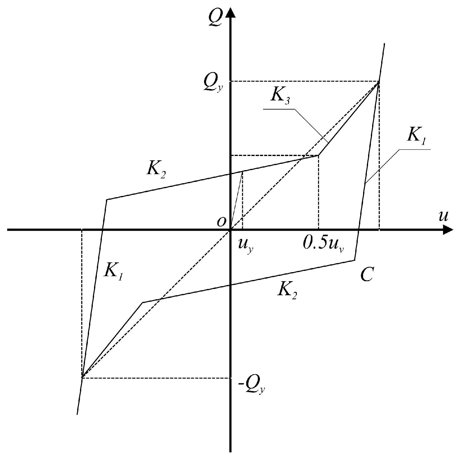
The annular steel wire rope damper is the primary energy dissipation component. Its hysteretic characteristics can be modeled by a tri-linear force-displacement relationship, which effectively captures the elastic stage, yielding stage, and strain hardening stage under cyclic loading. The restoring force F d a m p e r versus displacement u is defined as:
F d a m p e r ( u ) = K 1 u                                                                                                 u u y sgn ( u ) Q y + K 2 ( u u y )               u y < u u h   sgn ( u ) F h + K 3 ( u u h )             u > u h
where K 1 is the initial elastic stiffness, Q y and u y are the yield force and yield displacement, respectively, and K 2 and K 3 are the tangent stiffnesses at the first and second hardening stages, respectively. The typical hysteretic curve of this model is shown in Figure 2.

3. Dynamic Model of Continuous Rigid-Frame Bridge with New Isolation Bearing

3.1. Equation of Motion of the Isolated Bridge

For a bridge structural system incorporating highly nonlinear elements, its dynamic equation in the finite element form under the ground motion u ¨ g ( t ) can be written as:
M u ¨ t + C u ˙ t + K u t = M u ¨ g t
where M , C and K are the structural mass, damping, and stiffness matrices, respectively.
For the overall stiffness matrix K, the continuous rigid frame bridge is assumed to be composed of three-dimensional beam elements. The element stiffness matrix K e can be obtained by performing a numerical integration on B T D B at the integration points, which is written as:
K e = Ω B T D B d V
where B is the strain-displacement relationship matrix, and D is the material constitutive matrix.
According to the nodal degrees of freedom in the whole system, summing up the element stiffness matrices yields the total stiffness matrix K , as:
K = K e
Similarly, the mass matrix M can be determined. Afterwords the damping is assumed as the Rayleigh damping, and the damping matrix C is represented as:
C = α M + β K
where α and β are the damping coefficients, which are calculated, respectively, as:
α = 2 ω 1 ω 2 ω 1 ξ 2 ω 2 ξ 1 / ω 1 2 ω 2 2
β = ω 1 ξ 1 ω 2 ξ 2 / ω 1 2 ω 2 2
where ω 1 and ω 2 are the first two frequencies, respectively, ξ 1 and ξ 2 are the damping ratios of the first two vibration modes of the structure, respectively.

3.2. Soil-Structure Interaction Modeling

To reflect the influence of pile foundation on the seismic responses of the bridge, this study considers pile-soil-structure interaction in the modeling. The interaction between the pile foundation and the surrounding soil is equivalently simulated using the classic Winkler beam-on-elastic-foundation model, i.e., treating the continuous soil as a series of discretely arranged, independent spring elements along the pile length.
The stiffness of the springs is determined according to the m-method or named subgrade reaction modulus method recommended by the Chinese highway bridge foundation design code in the reference [36]. The core assumption is that the soil resistance at any depth along the pile is proportional to the horizontal displacement at that point, with the proportionality constant m directly related to soil type and properties. Although linear in essence, this model effectively captures the influence of foundation flexibility and provides a more realistic representation of structural dynamics compared to fully fixed boundary conditions.
The horizontal and rotational soil spring stiffnesses for a single pile may be calculated, respectively, by:
k h = m b 1 h
k θ = k h h 2 12
where m is the horizontal resistance coefficient of foundation soil, b 1 is the pile calculation width where for round piles, b 1 = 0.9(1.5d + 0.5) and d is the pile diameter, and h is the representative soil layer thickness.
For pile group foundations, the pile-pile interaction is considered by introducing a group efficiency factor η, which reduces the single pile stiffness. According to specifications, η is typically between 0.6 and 0.9.

4. Engineering Case

4.1. Engineering Background

The case of this study is the Pingchuan Yellow river bridge, which is a key transportation hub spanning the Yellow river. The main bridge is a long-span prestressed concrete continuous rigid-frame bridge, with a total length of 1626 m. The main bridge adopts a three-span continuous arrangement, with a span combination of (900 + 1600 + 900) meters. The overall elevation layout and typical cross-sections of the bridge are shown in Figure 3.
The main girder adopts a single-box, single-cell variable cross-section box girder. The top slab of the box girder is 12.55 m wide, and the bottom slab is 6.75 m wide. The girder height transitions smoothly from 8.8 m at the middle pier support to 3.8 m at midspan, following a quadratic parabola. The main girder is made of C55 high-strength concrete.
The main piers use hollow piers with double thin-walled form, with a height range of 35 to 55 m. The cross-sectional dimensions of the piers are 8.0 m by 3.0 m, with a wall thickness of 0.6 m. The piers are constructed with C40 concrete.
Given its location in a high seismic intensity region and its complex structural form, proposing an efficient seismic protection scheme for this bridge is both a core challenge and a key focus in the project design.

4.2. Finite Element Model of the Bridge

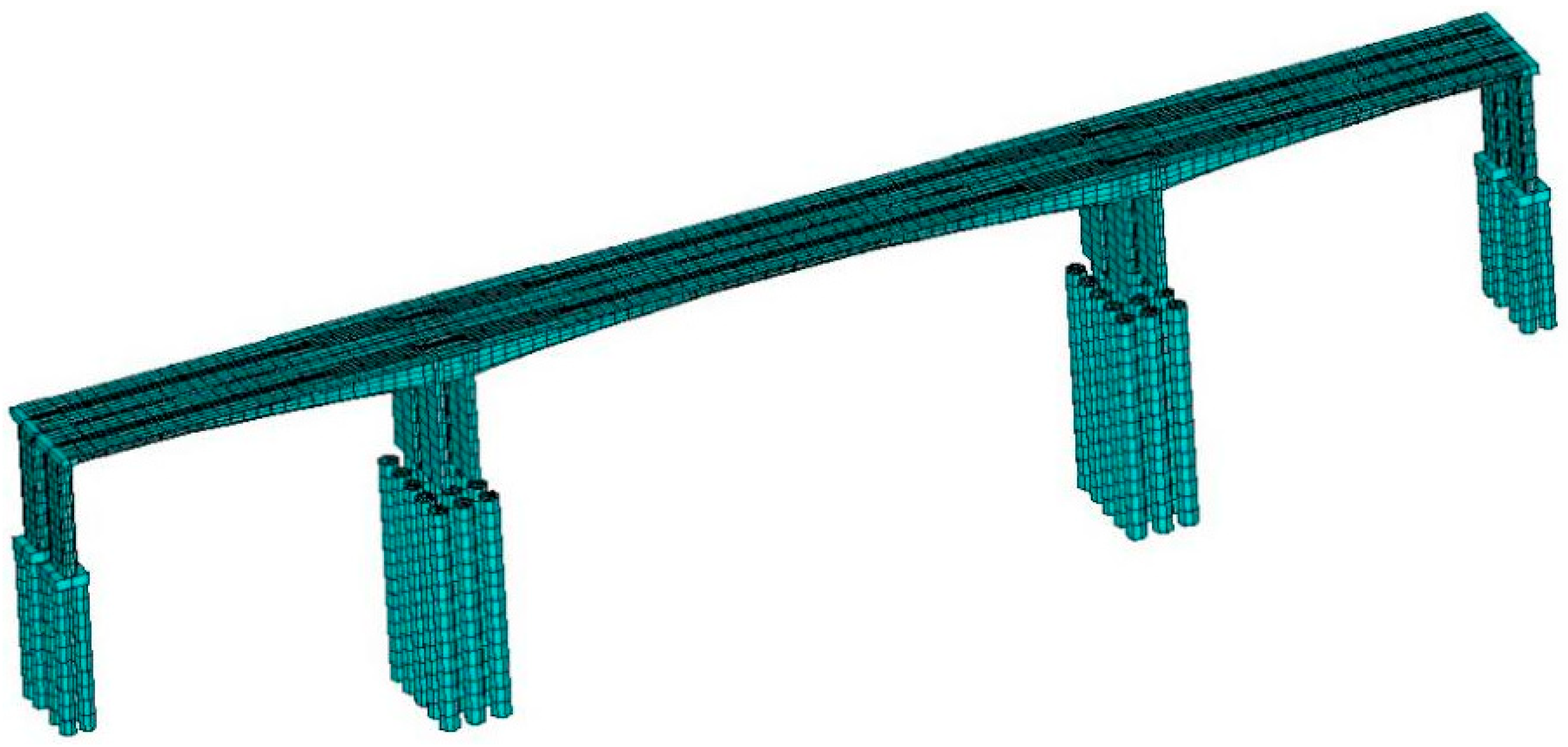
Based on the software ANSYS (v2021R1), a three-dimensional nonlinear finite element model for the Pingchuan Yellow river bridge was established, as shown in Figure 4. The main girder and piers are simulated using BEAM188 elements with shear deformation considered, where each node has 6 degrees of freedom including translations and rotations, while pile caps are modeled using Shell elements. The model contains 3396 nodes and 2950 elements.
According to the m-method in the Chinese seismic design code for highway bridges, the pile-soil interaction is considered using COMBIN40 elements to simulate soil springs and equivalent horizontal and rotational restraints [36]. The secondary dead load is applied as a distributed linear mass on the main girder.
The tri-linear hysteretic characteristic of the annular steel wire rope damper spherical bearing is simulated using the COMBIN39 element in combination with the COMBIN40 element. Ordinary bearings are simulated with a single spring element. The body of the spherical bearing is modeled with elastic link elements, setting the vertical stiffness to 1 × 10⁹ kN/m, and horizontal stiffness is calculated according to the code. The steel wire rope damper is represented with nonlinear connection elements, and multi-segment plastic kinematic model parameters are input accordingly. And the key design parameters of the bearing are listed in Table 1.
The Winkler springs are simulated using COMBIN40 elements, which can define both spring stiffness and damping properties. The COMBIN40 springs for both horizontal and rotational direction are attached at each node. The computed values of k h and k θ are input as real constants in the respective COMBIN40 elements. The pile base node is fully fixed, and the pile head is coupled to the pile cap. In this study, the group efficiency factor η is 0.8.

4.3. Ground Motion Input

Through seismic hazard analysis by the Gansu provincial institute of earthquake engineering, the earthquake ground motion characteristics at the bridge site are determined, and the design response spectra are provided for various exceedance probabilities.
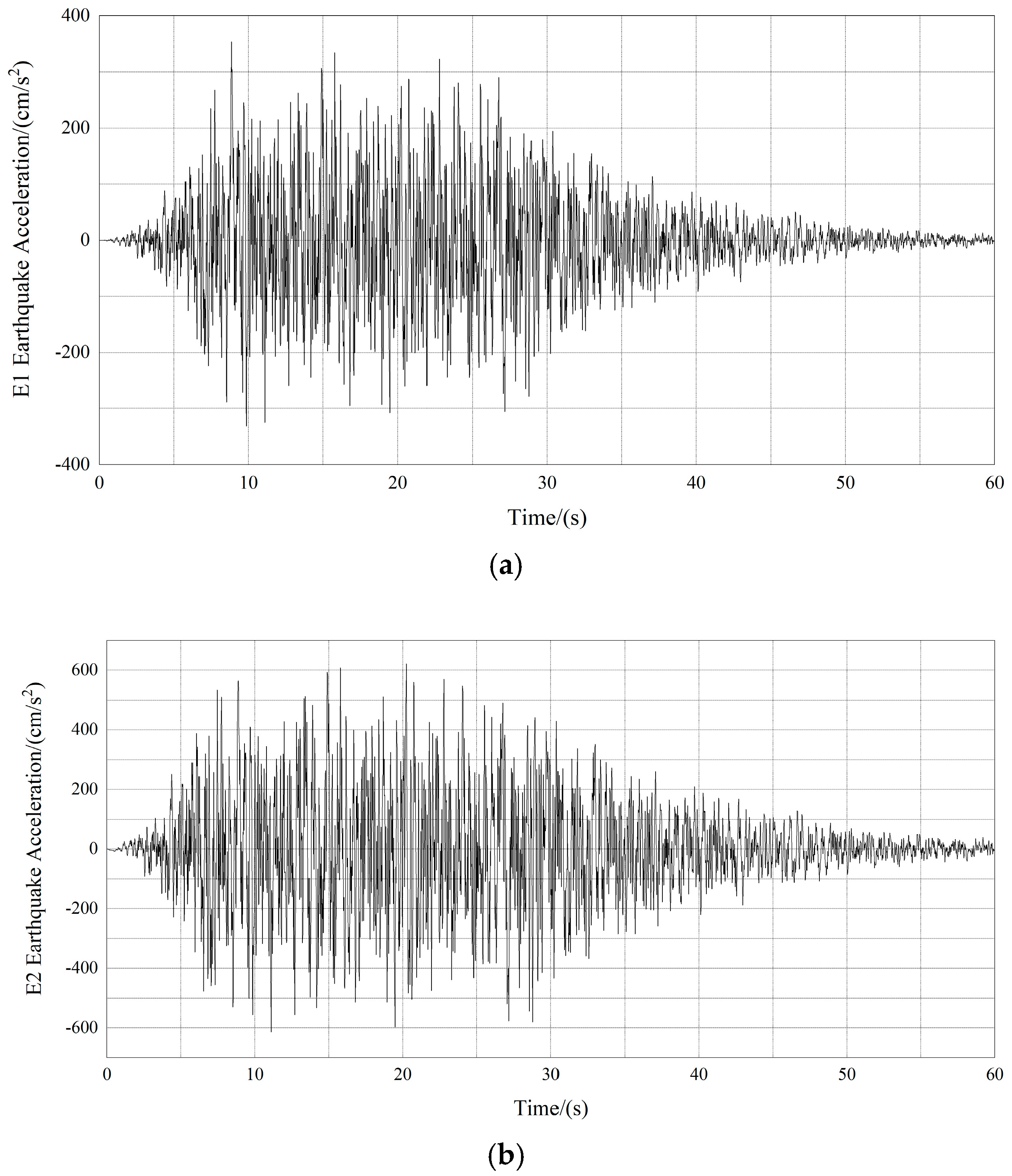
Two levels of seismic hazards are adopted for dynamic analysis. About the E1 earthquake, which represents the seismic scenario with a 10% exceedance probability in 50 years, the peak ground acceleration (PGA) is approximately 0.33 g. For the E2 earthquake, corresponding to the seismic scenario with a 5% exceedance probability in 100 years, the PGA of the earthquake reaches approximately 0.64 g. In addition, the characteristic period of the construction site is about 0.45 s.
According to the Chinese seismic code, the Pingchuan Yellow river bridge requires all main components to basically remain elastic under the E2 earthquake, regardless of isolation or conventional ductility design. The artificial ground motion time histories for E1 and E2 are generated using the design response spectra, which are plotted in Figure 5.

4.4. Seismic Design Criteria and Static Responses

Considering that the site is of seismic intensity VIII and soil category II, it is required that under the E1 earthquake, the section moment of the piers and pile foundations does not exceed the initial yield moment Under the E2 earthquake, the section moment must not exceed the equivalent flexural yield moment. According to the stress characteristics of the Pingchuan Yellow river bridge under seismic loads, the most unfavorable section is selected as the critical section and is divided into fiber elements. The contributions of both reinforcement and concrete to the section capacity are taken into account according to the actual reinforcement arrangement.
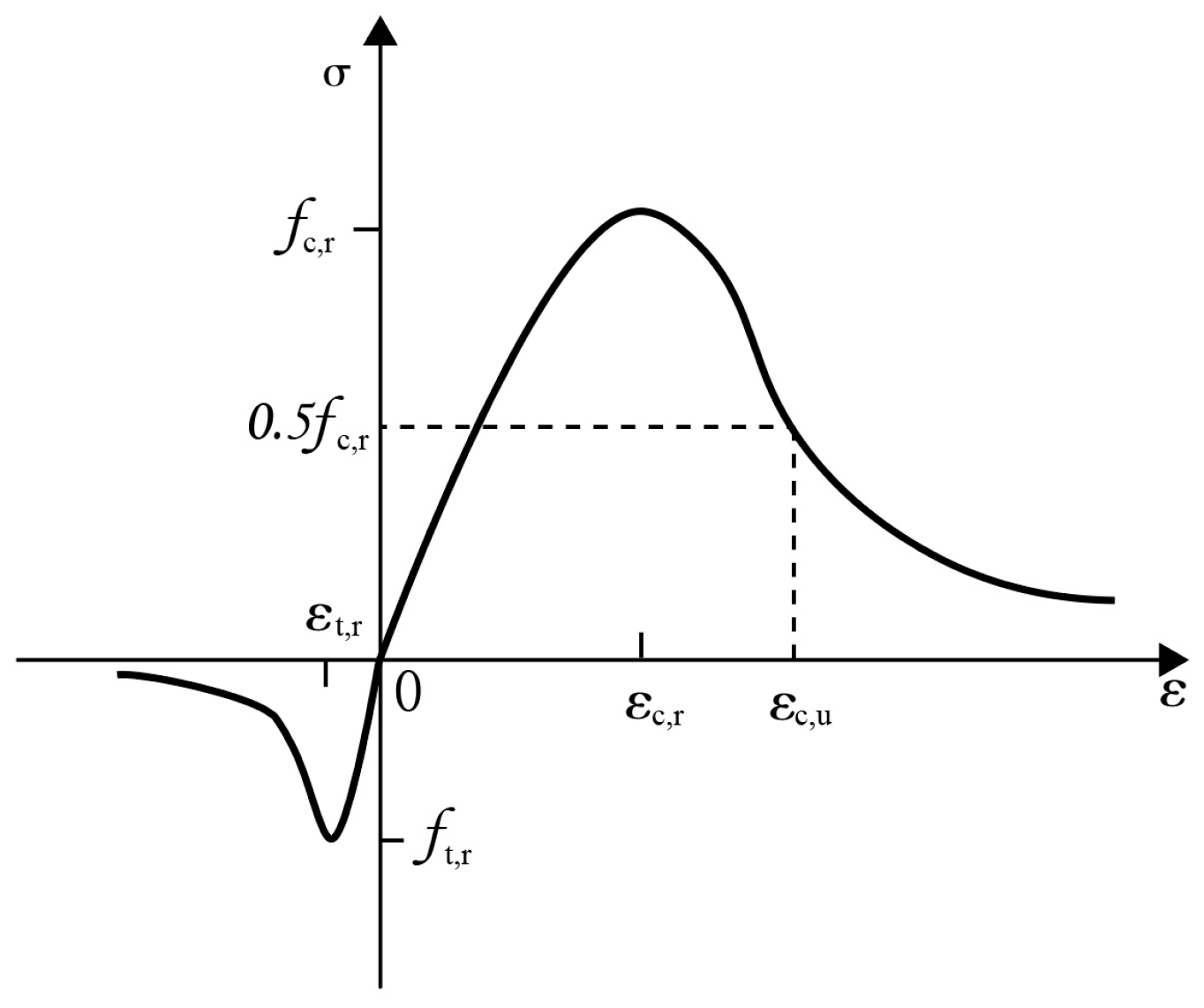
The concrete stress–strain relationship, which is adopted from the design code of concrete structures [37], is shown in Figure 6. The section moment–curvature analysis is performed using the numerical integration, as plotted in Figure 7. In Figure 7, M y represents the initial yield moment corresponding to the first yielding of the outermost rebar in the section, and M e q represents the equivalent flexural yield moment of the section.
To evaluate the load effects of the Pingchuan Yellow river bridge, the responses of the bridge under the static load are calculated at first. As an example, the unfavorable axial forces of the critical sections for the piers and the pile foundations attached to the piers under the static load are shown in Table 2.

4.5. Seismic Responses

In order to accurately assess the protective effect of the SWD-SB for the large-span continuous rigid-frame bridge under the strong earthquake excitation, this section calculates the basic dynamic characteristics and seismic responses of the bridge under the E1 and E2 earthquakes.

4.5.1. Basic Dynamic Characteristics

Using the finite element model of the Pingchuan Yellow river bridge, the first eight periods, frequencies and modal shape characteristic of the structure are calculated, and listed in Table 3.

4.5.2. Seismic Responses Under the E1 Earthquake

Assuming that the E1 earthquake occurs, this section calculates the seismic responses of the Pingchuan Yellow river bridge the bidirectional movable pot bearings and the SWD-SB bearings, respectively. On this basis, considering the most unfavorable combination of static load and earthquake, the internal force values on critical sections are determined.
In the case of using the bidirectional movable pot bearings, under the E1 earthquake, the longitudinal and vertical earthquake waves are input simultaneously. Taking the most unfavorable combination of the static load and earthquake into account, the internal force response results on the critical sections of piers and piles are shown in Table 4, where the ratio of capacity to demand is provided following the seismic design criteria given on the above.
After installing the steel wire rope damper isolators, the response results under the longitudinal and vertical E1 earthquake excitations are shown in Table 5.

4.5.3. Seismic Responses Under the E2 Earthquake

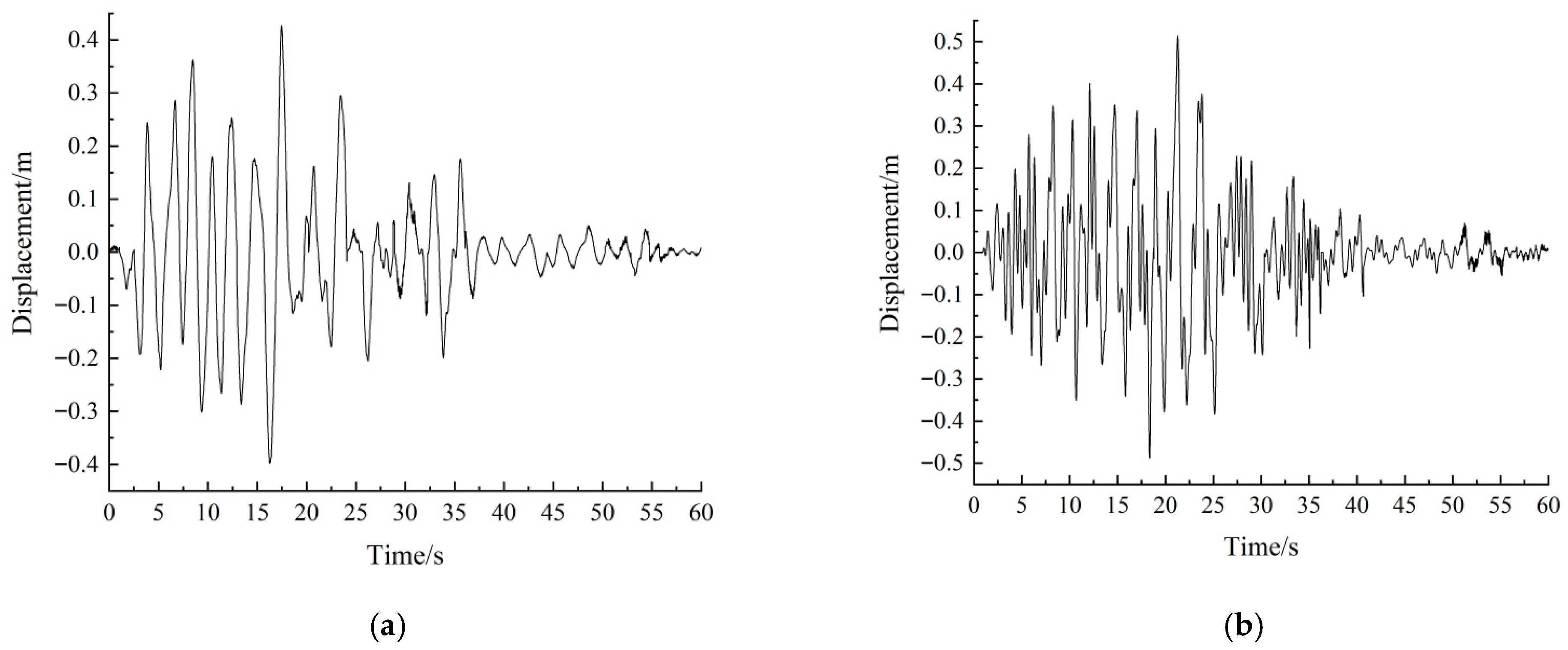
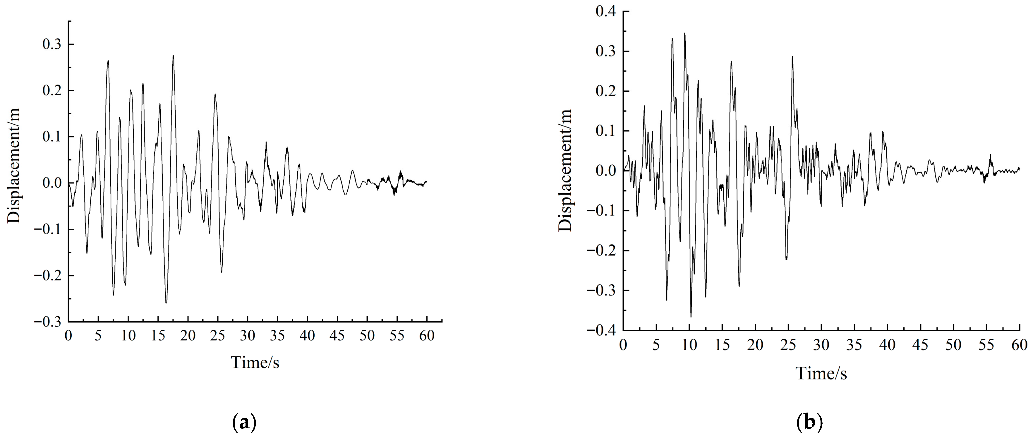
Under the E2 earthquake, both the longitudinal and vertical ground motions are considered. The internal force response results of critical sections of the piers and piles are given in Table 6, and the displacement time history at the top of Pier 2 is shown in Figure 8.
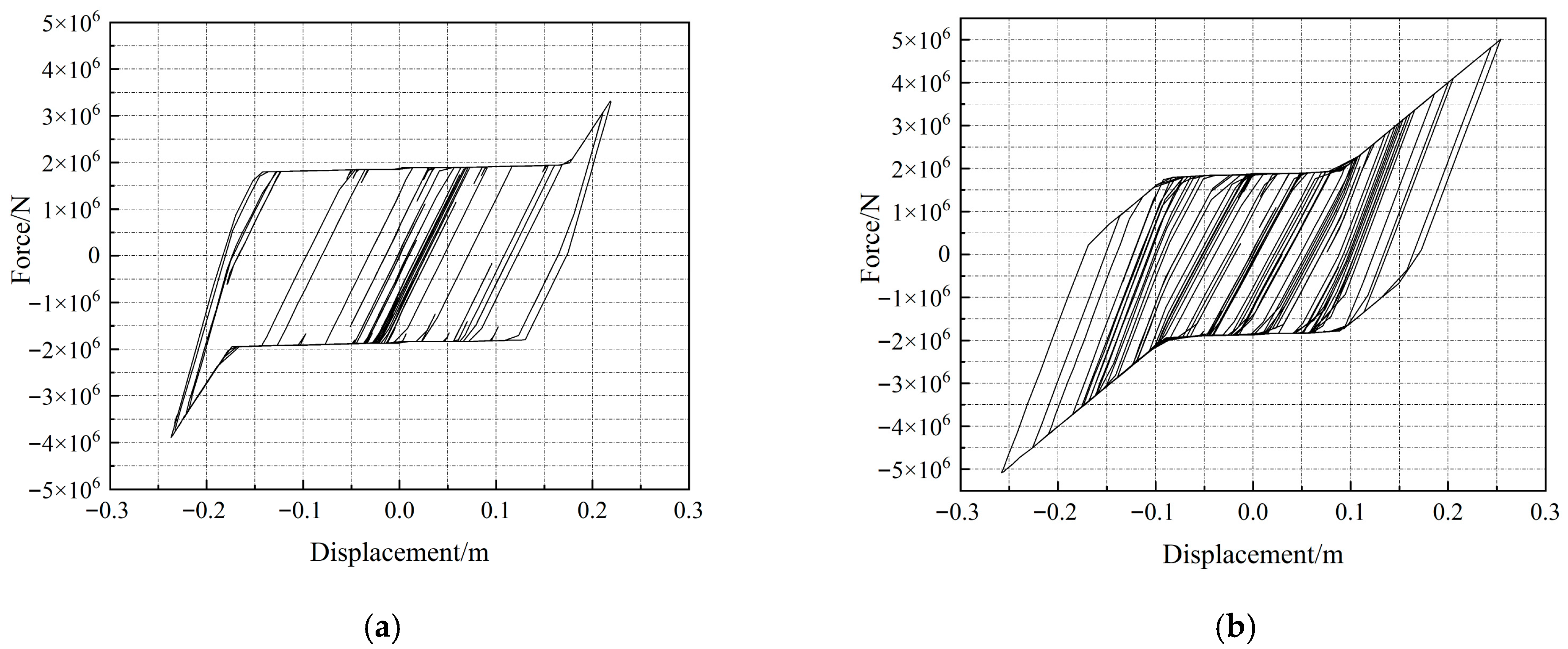
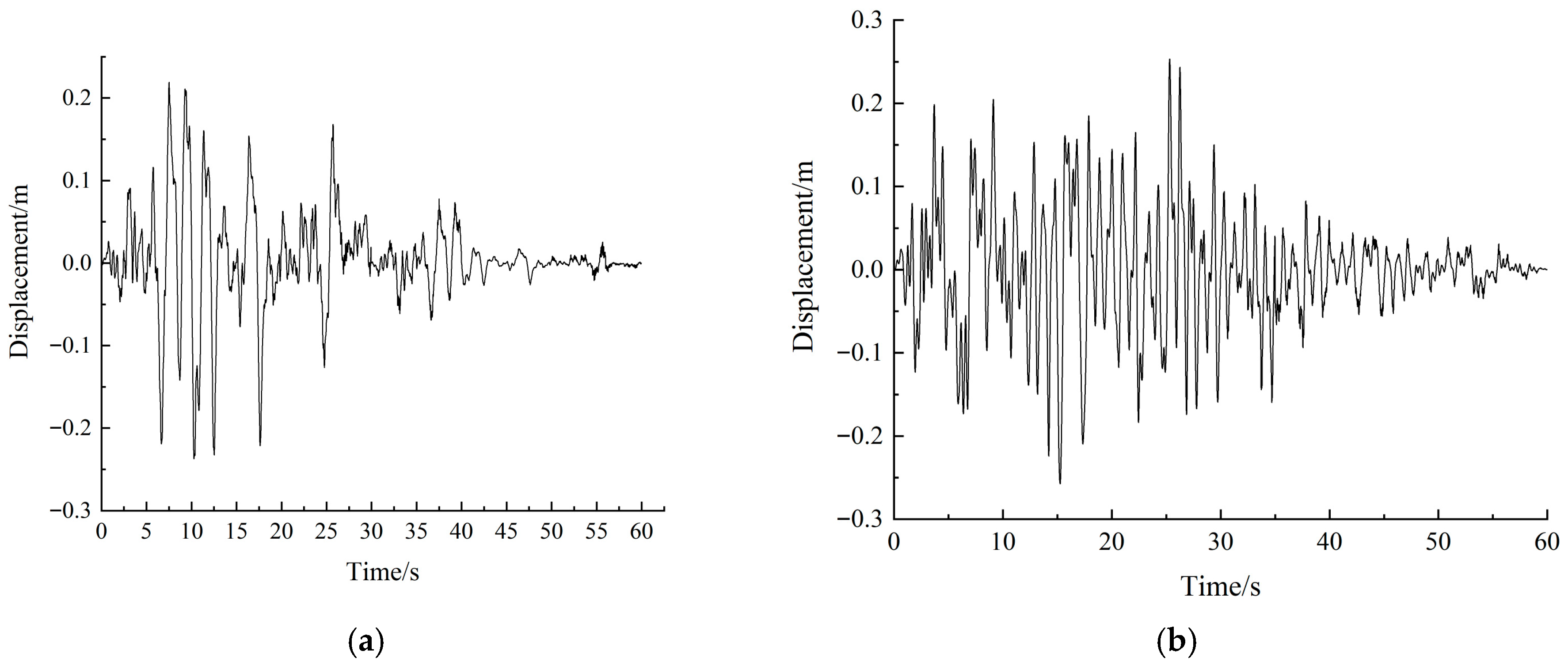
With the SWD-SB bearings installed, under the E2 earthquake longitudinally and vertically input, the critical internal forces are shown in Table 7. The time history response of pier-top displacements are illustrated in Figure 9, the hysteresis curves for the isolation bearing are plotted in Figure 10, and the bearing displacement is shown in Figure 11.
Taking the temperature effect into consideration, the displacement verification for SWD-SB is shown in Table 8.

4.5.4. Result Analysis

From the above calculation results including Table 5, Table 6, Table 7 and Table 8 and Figure 9, Figure 10 and Figure 11, it is found that, under the longitudinal E2 earthquake, compared with those with the bidirectional movable pot bearings, the base moments of Piers 1 and 4 using SWD-SB are reduced by up to 35%, and the pile-top moments decrease by up to 44.7%. For Piers 2 and 3, the base moments are reduced by up to 23.2%, and the pile-top moments decrease by up to 10.6%. Taking the temperature effect into account, the maximum displacement of the SWD-SB is 0.291 m, which is located in the required range.
Under the transverse E2 earthquake, when comparing with that using the bidirectional movable pot bearings, the base moments of Piers 1 and 4 with SWD-SB are reduced by up to 72.6%, and the pile-top moments are decreased by up to 10.1%. For Piers 2 and 3, the base moment is reduced by up to 24%, and the pile-top moments decrease by up to 10.4%. The maximum isolator displacement is 0.295 m, which satisfies the design requirement.
The results demonstrate that by using SWD-SB, the main piers and pile foundations of the Pingchuan Yellow river bridge remain elastic under the E2 earthquake, thus meeting the two-level, two-stage seismic design objectives.

5. Conclusions

In this study, based on the novel SWD-SB bearing, the dynamic model of a continuous rigid-frame bridge is established, where a three-dimensional finite element model with nonlinear bearing elements is constructed. Meanwhile the soil–structure interaction is considered. In the engineering case, the seismic response analysis of the Pingchuan Yellow river bridge is conducted under differential levels of earthquakes. The main conclusions are as follows:
  • If the large-span continuous rigid-frame bridge located in the strong seismic zone do not employ effective seismic protection measures, its inherent capacity of dissipating seismic input energy is insufficient. The use of SWD-SB can effectively enhance the energy dissipation of the large-span continuous rigid-frame bridge during the strong earthquake. The force–displacement relationship of the steel wire rope damper isolator bearing is subjected to the trilinear hysteretic model as designed. This device can greatly reduce the displacement responses of the bridge under the strong earthquake and achieve a certain degree of self-centering. Additionally, it provides anti-unseating protection, thus offering strong support for subsequent bridge maintenance and structural recovery.
  • Under the E2 earthquake scenario, compared to the bidirectional movable pot bearings, the use of SWD-SB significantly reduces the seismic internal forces and displacements of the piers and pile foundations. Specifically, the maximum reduction in the pier base moment reaches 72.6%, and the reduction in pier-top displacement ranges from 20% to 34.6%. The isolator’s maximum displacement remains within the allowable design value range, demonstrating the excellent energy dissipation and isolation performance.
  • The implementation of SWD-SB can offer the reliable seismic protection for large-span continuous rigid-frame bridges in the strong earthquake zone studied in this paper. The modeling and assessment approach presented in this paper can provide a reference for the similar bridge design and seismic evaluation projects.

Author Contributions

Conceptualization, X.L. and P.Z.; Methodology, Y.C.; Theoretical analysis and manuscript preparation, B.H. Software and calculation, Z.W. (Zhifeng Wu) and K.Y.; Writing and validation, Z.W. (Zhijun Weng). All authors have read and agreed to the published version of the manuscript.

Funding

This research is funded by the National Natural Science Foundation of China (Grant No. 51978545).

Data Availability Statement

The original contributions presented in this study are included in the article. Further inquiries can be directed to the corresponding author.

Conflicts of Interest

Authors Xiaoli Liu and Yongzhi Chen were employed by the company Gansu Communication Investment Management Co., Ltd. Author Penglei Zhao was employed by the company CCCC Second Highway Consultants Co., Ltd. The remaining authors declare that the research was conducted in the absence of any commercial or financial relationships that could be construed as a potential conflict of interest.

References

  1. Yu, J.; Zhang, J.; Li, P.; Han, X. Influence of Superstructure Pouring Concrete Volume Deviation on Bridge Performance: A Case Study. Buildings 2023, 13, 887. [Google Scholar] [CrossRef]
  2. Rashedi, S.H.; Rahai, A. Experimental and numerical advances in seismic assessment of continuous RC rigid-frame bridges: A review. Results Eng. 2025, 26, 105656. [Google Scholar] [CrossRef]
  3. Chen, Y.; Yang, X.T.; Wu, K.; Huang, X.; Li, Z.-X. Damage analysis of a reinforced concrete rigid-frame bridge under combined strong earthquake and wave action. Ocean. Eng. 2024, 296, 116919. [Google Scholar] [CrossRef]
  4. Liang, Y.; Yan, L.J.; Qian, W.X.; Cheng, Z.Q.; Chen, H. Analysis of collapse resistance of offshore rigid frame-Continuous girder bridge based on time-varying fragility. Mar. Struct. 2021, 75, 102844. [Google Scholar] [CrossRef]
  5. Al-Attraqchi, A.Y.; Hashemi, M.J.; Al-Mahaidi, R. Loss assessment of rigid-frame bridges under horizontal and vertical ground motions. Structures 2022, 35, 243–259. [Google Scholar] [CrossRef]
  6. Li, X.; Li, Z.X.; Crewe, A.J. Nonlinear seismic analysis of a high-pier, long-span, continuous RC frame bridge under spatially variable ground motions. Soil Dyn. Earthq. Eng. 2018, 114, 298–312. [Google Scholar] [CrossRef]
  7. Liu, Y.; Mei, Z.; Wu, B.; Bursi, O.S.; Dai, K.; Li, B.; Lu, Y. Seismic behaviour and failure-mode-prediction method of a reinforced-concrete rigid-frame bridge with thin-walled tall piers: Investigation by model-updating hybrid test. Eng. Struct. 2020, 208, 110302. [Google Scholar] [CrossRef]
  8. Liu, X.; Fan, J.; Nie, J.; Li, G. Behavior of composite rigid frame bridge under bi-directional seismic excitations. J. Traffic Transp. Eng. (Engl. Ed.) 2014, 1, 62–71. [Google Scholar] [CrossRef]
  9. Liu, Z.; Liu, Z.; Ai, Q.; Ruan, X. Global reliability evaluation of a high-pier long-span continuous RC rigid frame bridge subjected to multi-point and multi-component stochastic ground motions. Soil Dyn. Earthq. Eng. 2023, 164, 107623. [Google Scholar] [CrossRef]
  10. Shi, Y.; Wang, W.; Qin, H.; Shi, Y.; Jiao, Y. Nonlinear seismic response and damage analysis for continuous prestressed concrete rigid-frame bridge considering internal force state under near-fault ground motions. Structures 2024, 61, 105993. [Google Scholar] [CrossRef]
  11. Zhao, J.; Jia, H.; Zhan, Y. Seismic vulnerability analysis of multi-main-span high pier continuous rigid-frame bridge in terms of cloud method. KSCE J. Civ. Eng. 2023, 27, 2519–2534. [Google Scholar] [CrossRef]
  12. Tong, L.; Wang, D.; Zou, Y.; Shi, F.; Sun, Z. Seismic performance and damage control of large-span prestressed concrete rigid-frame bridges with high piers crossing strike-slip faults. Soil Dyn. Earthq. Eng. 2024, 177, 108412. [Google Scholar] [CrossRef]
  13. Tong, L.; Wang, D.S.; Sun, Z.G.; Shi, F.; Dai, J.-C. Seismic performance and control methods of end span uplift for long-span rigid-frame bridges subjected to near-fault ground motions. Structures 2024, 64, 106567. [Google Scholar] [CrossRef]
  14. Lin, Y.; Zong, Z.; Bi, K.; Hao, H.; Lin, J.; Chen, T. Experimental and numerical studies of the seismic behavior of a steel-concrete composite rigid-frame bridge subjected to the surface rupture at a thrust fault. Eng. Struct. 2020, 205, 110105. [Google Scholar] [CrossRef]
  15. Wang, S.; Xu, W.; Wang, J.; Huang, X.; Sun, H.; Ma, J.; Chen, Y. Shaking table test on seismic performance of continuous rigid frame bridge with cast-in-place and fabricated super high piers. Structures 2022, 46, 369–381. [Google Scholar] [CrossRef]
  16. Zhang, L.; Ji, Z.; Wu, H.; Qi, L.; Chen, J.; Zhang, S. Mechanical behavior of steel-concrete joint area (SCJA) in hybrid girder continuous rigid frame bridge. Eng. Struct. 2025, 334, 120230. [Google Scholar] [CrossRef]
  17. Zhang, W.; Liu, Y.; Chen, Y.; Du, X. Study on the pier bottom self-centering seismic isolation structure of the high-pier continuous rigid frame bridges. Soil Dyn. Earthq. Eng. 2023, 174, 108189. [Google Scholar] [CrossRef]
  18. Zheng, W.; Chen, J.; Wang, H.; Tan, P.; Li, J.; Wang, S. A novel damping adaptive pendulum isolation system for seismic resilience enhancement of continuous bridges. Eng. Struct. 2025, 339, 120465. [Google Scholar] [CrossRef]
  19. He, J.; Han, Z.; Pang, Y.; Yuan, W. Seismic performance assessment of bridges isolated by a new restorable cable-sliding bearing. Eng. Struct. 2025, 327, 119578. [Google Scholar] [CrossRef]
  20. Jiang, S.; Ma, R.; Bi, K.; Li, H.; Du, X. Negative stiffness enhanced TMD for seismic response mitigation of bridges isolated with friction pendulum system (FPS). Eng. Struct. 2025, 331, 119978. [Google Scholar] [CrossRef]
  21. Liu, P.; Li, J.; Gao, J.; Jiang, X.; Qu, H. Seismic performance of hybrid seismic isolation bearing system: Shake table test and nonlinear numerical analysis. Soil Dyn. Earthq. Eng. 2025, 196, 109452. [Google Scholar] [CrossRef]
  22. Zou, S.; Wang, H.; Fang, S.; Fang, Z.; Wenliuhan, H.; Qu, C.; Zhang, C. Seismic isolation effect and parametric analysis of simply supported beam bridges with multi-level sliding friction adaptive isolation bearing. Soil Dyn. Earthq. Eng. 2025, 188, 109000. [Google Scholar] [CrossRef]
  23. Yuan, W.; Xie, B.; Zhou, W.; Yin, Z.; Wang, Z.; Ding, T. Seismic performance analysis of wind and rain bridge structures and design of a seismic vibration damping program using rubber isolators. Structures 2025, 79, 109474. [Google Scholar] [CrossRef]
  24. Dong, J.; Leng, D.; Zeng, Y. Shaking table test of a high-speed railway bridge with combined seismic isolation systems in a nine-degree seismic region. Structures 2024, 63, 106270. [Google Scholar] [CrossRef]
  25. Tan, K.C.; Hejazi, F.; Esfahani, H.M.; Chong, T. Development of elastomeric rubber bearing utilizing core-and-filler system. Structures 2022, 37, 125–139. [Google Scholar] [CrossRef]
  26. Gottesfeld, P.; Were, F.H.; Adogame, L.; Gharbi, S.; San, D.; Nota, M.M.; Kuepouo, G. Soil contamination from lead battery manufacturing and recycling in seven African countries. Environ. Res. 2018, 161, 609–614. [Google Scholar] [CrossRef] [PubMed]
  27. Hu, S.; Yang, M.; Meng, D.; Hu, R. Damping performance of the degraded fluid viscous damper due to oil leakage. Structures 2023, 48, 1609–1619. [Google Scholar] [CrossRef]
  28. He, Q.; Ling, K.; Zhao, G.; Liu, D.; Yao, S.; Lei, M.; Sun, W. Seismic response analysis of overall friction pendulum bearing (OFPB) isolated structures. Structures 2024, 68, 107224. [Google Scholar] [CrossRef]
  29. Konar, T.; Ghosh, A.D. Tuned mass damper inerter for seismic control of multi-story buildings: Ten years since inception. Structures 2024, 63, 106459. [Google Scholar] [CrossRef]
  30. Huang, W.; Liu, G.; Zhang, H.; An, Y. Study on a novel type of metallic damper. J. Build. Eng. 2025, 101, 111854. [Google Scholar] [CrossRef]
  31. Wang, W.; Chen, S.; Chen, B.; Liu, G.; Hua, X.; Chen, Z. Development and application of metallic dampers in bridge engineering: A review. J. Traffic Transp. Eng. (Engl. Ed.) 2025, 12, 236–268. [Google Scholar] [CrossRef]
  32. Lai, K.; Fan, W.; Chen, Z.; Yang, C.; Liu, Z.; Li, S. Performance of wire rope damper in vibration reduction of stay cable. Eng. Struct. 2023, 278, 115527. [Google Scholar] [CrossRef]
  33. Lai, K.; Fan, W.; Chen, Z.; Niu, H.; Ma, L.; Li, S. Optimal design of transverse dampers incorporating inherent stiffness effects for stay cable vibration control: A case study with wire rope dampers. Eng. Struct. 2024, 308, 118015. [Google Scholar] [CrossRef]
  34. T/CECS G:J61-01-2021; Technical Specifications for Seismic Response Reduction of Highway Bridges with Steel Wire Rope Damping Devices. China Communications Press: Beijing, China, 2021. (In Chinese)
  35. T/CHTS 20017-2021; Annular Wire-Rope Composite Damping Bearings for Highway Bridges. China Communications Press: Beijing, China, 2021. (In Chinese)
  36. JTG/T 2231-01-2020; Guidelines for Seismic Design of Highway Bridges. China Communications Press: Beijing, China, 2020. (In Chinese)
  37. GB 50010-2010; Code for Design of Concrete Structures [2015 Edition]. Architecture & Building Press: Beijing, China, 2015. (In Chinese)
Figure 1. Structural configuration of SWD-SB: (a) Overall schematic diagram; (b) Sectional view.
Buildings 15 03249 g001
Figure 2. Force−displacement relationship of the SWD-SB.
Buildings 15 03249 g002
Figure 3. Layout of the main bridge type of Pingchuan Yellow river bridge.
Buildings 15 03249 g003
Figure 4. Finite element model of the Pingchuan Yellow river bridge.
Buildings 15 03249 g004
Figure 5. Artificial earthquake waves for the E1 and E2 scenarios: (a) E1 wave; (b) E2 wave.
Buildings 15 03249 g005
Figure 6. Stress–strain relationship of concrete material.
Buildings 15 03249 g006
Figure 7. Sectional moment–curvature curve.
Buildings 15 03249 g007
Figure 8. Time history curves of displacement at the top of Pier 2 under the E2 earthquake: (a) Longitudinal bridge input; (b) Transverse bridge input.
Buildings 15 03249 g008
Figure 9. Displacement time history curves of at the top of Pier 2 under the E2 earthquake with SWD−SB: (a) Longitudinal bridge input; (b) Transverse bridge input.
Buildings 15 03249 g009
Figure 10. The hysteresis curves of the SWD−SB bearings under the E2 earthquake: (a) Longitudinal bridge input; (b) Transverse bridge input.
Buildings 15 03249 g010
Figure 11. Displacement responses of the SWD−SB bearings under the E2 earthquake: (a) Longitudinal bridge input; (b) Transverse bridge input.
Buildings 15 03249 g011
Table 1. Key design parameters of the SWD-SB.
ParameterSymbolValueUnit
Yield forceK0909kN
Yield displacementQy38mm
Hardening onset forceQh1117kN
Hardening onset displacementuh150mm
Maximum damping forceQc2853kN
Maximum working displacementuc300mm
Shear equivalent stiffnessKeq9.51kN/mm
Equivalent damping ratio ξ e q 0.20/
Table 2. Axial forces of piers and pile foundations under the dead load.
ComponentPier (kN)Pile (kN)
Pier 1−20,016−6927
Pier 2−45,390−15,451
Pier 3−45,864−15,370
Pier 4−20,118−6938
Note: Negative values indicate compression.
Table 3. Basis dynamic characteristics of the bridge.
Mode OrderPeriod (s)Frequency (Hz)Modal Shape Description
12.030.4927Longitudinal vibration of main girder
21.9720.507Antisymmetric longitudinal vibration of main girder
31.210.83Transverse vibration of main girder
41.190.84Antisymmetric transverse vibration of main girder
50.9971.003Symmetric transverse vibration of main girder
60.9871.013Antisymmetric transverse vibration of main girder
70.9571.045Symmetric transverse vibration of main girder
80.9461.057Antisymmetric transverse vibration of main girder
Table 4. Internal force responses of piers and piles with the bidirectional movable pot bearings.
Load CombinationSection PositionAxial Force/kNBending Moment/kN·mInitial Yield Bending Moment/kN·mCapacity/Demand
E1 (Longitudinal + Vertical) + Static loadBottom of Pier 1−5570−123,708154,8831.25
Bottom of Pier 2−31,101−189,777281,0681.48
Bottom of Pier 3−30,573−194,526317,7301.63
Bottom of Pier 45791−117,081163,0741.39
Top of Pile for Pier 1−5.978 × 10312,48714,7731.18
Top of Pile for Pier 2−1.344 × 10437,20934,6670.93
Top of Pile for Pier 31.343 × 10429,90433,8111.13
Top of Pile for Pier 4−3.598 × 10311,11411,5891.04
E1 (Transverse + Vertical) + Static loadBottom of Pier 1−9749−493911366,4930.74
Bottom of Pier 245,091760,259785,2861.03
Bottom of Pier 346,986790,548959,8881.21
Bottom of Pier 4−2437−611,172371,2720.61
Top of Pile for Pier 1−12,613−595882371.38
Top of Pile for Pier 2−42,374−32,80825,3760.77
Top of Pile for Pier 337,503−29,39225,7570.87
Top of Pile for Pier 419,921−6468/Tensile failure
Table 5. Internal force responses of piers and piles with SWD-SB.
Load CombinationSection PositionAxial Force/kNBending Moment/kN·mInitial Yield Bending Moment/kN·mCapacity/Demand
E1 (Longitudinal + Vertical) + Static loadBottom of Pier1−32,228108,514172,6701.59
Bottom of Pier 2−78,411−178,053258,1071.50
Bottom of Pier 3−50,195−173,824241,5731.39
Bottom of Pier 4−27,623110,372167,9801.52
Top of Pile for Pier 1−10,140−10,67919,1071.78
Top of Pile for Pier 2−693928,67835,1031.22
Top of Pile for Pier 3−6703−26,22634,9601.33
Top of Pile for Pier 4−957710,65718,8791.77
E1 (Transverse + Vertical) + Static loadBottom of Pier 1−38,660−254,449390,0731.53
Bottom of Pier 2−58,888−713,584948,3351.33
Bottom of Pier 3−59,207−653,897949,1151.45
Bottom of Pier 4−21,874266,765353,6451.33
Top of Pile for Pier 1−6971918717,8281.93
Top of Pile for Pier 2−43,84927,00153,9332.00
Top of Pile for Pier 3−37,73322,18151,4272.32
Top of Pile for Pier 4−6942919217,8161.94
Table 6. Internal force responses of piers and piles with the bidirectional movable pot bearings under the E2 earthquake.
Load CombinationSection PositionAxial Force/kNBending Moment/kN·mEquivalent Yield Bending Moment/kN·mCapacity/Demand
E2 (Longitudinal + Vertical) + Static loadBottom of Pier 1−13,652−254,900195,2250.76
Bottom of Pier 2−50,167295,467299,3360.90
Bottom of Pier 3−51,243−316,887301,7760.95
Bottom of Pier 4−9470250,402175,3450.82
Top of Pile for Pier 1−11,72025,72417910.70
Top of Pile for Pier 229,535−53,523/Tensile failure
Top of Pile for Pier 324,757−55,51740,346.330.73
Top of Pile for Pier 4−943623,17318,621.380.80
E2 (Transverse + Vertical) + Static loadBottom of Pier 1−22,622−921,811488,529.320.53
Bottom of Pier 254,7201,444,0421,229,2150.85
Bottom of Pier 366,2431,507,6231,525,3241.01
Bottom of Pier 4−13,380−1,166,755515,6710.44
Top of Pile for Pier 1−22,481−11,70448970.42
Top of Pile for Pier 267,86843,52330,8230.71
Top of Pile for Pier 389,11649,230/Tensile failure
Top of Pile for Pier 430,71312,461/Tensile failure
Table 7. Internal force responses with the SWD-SB bearings under the E2 earthquake.
Load CombinationSection PositionAxial Force/kNLongitudinal Bending Moment/kN·mEquivalent Yield Bending Moment/kN·mCapacity/Demand
E2 (Longitudinal + Vertical) + Static loadBottom of Pier 1−13,143−165,696200,1881.14
Bottom of Pier 2−74,475252,933314,2571.24
Bottom of Pier 3−96,921243,514327,1401.34
Bottom of Pier 4−10,128169,070197,1061.17
Top of Pile for Pier 1−16,30714,22426,1691.42
Top of Pile for Pier 2−47,94554,68061,7741.13
Top of Pile for Pier 3−46,846−49,62061,6371.24
Top of Pile for Pier 4−20,119−15,14826,9331.52
E2 (Transverse + Vertical) + Static loadBottom of Pier 1−22,911273,292461,1101.69
Bottom of Pier 2−115,307−1,097,9501,524,1911.39
Bottom of Pier 3−115,1301,281,8701,523,7771.19
Bottom of Pier 4−24,485−319,532464,3291.45
Top of Pile for Pier 112,53310,52419,6761.87
Top of Pile for Pier 2−84,324−43,07458,3111.36
Top of Pile for Pier 3−85,512−44,10857,9361.31
Top of Pile for Pier 414,781−12,38712,9091.04
Table 8. Displacement verification for the SWD-SB bearings.
Input EarthquakeSeismic Displacement of Bearing/mTemperature Displacement/mCombination Displacement/mBearing Design Displacement/mExceeding of the Limit
Longitudinal 0.2370.0540.2910.3No
Transverse0.2410.0540.2950.3No
Disclaimer/Publisher’s Note: The statements, opinions and data contained in all publications are solely those of the individual author(s) and contributor(s) and not of MDPI and/or the editor(s). MDPI and/or the editor(s) disclaim responsibility for any injury to people or property resulting from any ideas, methods, instructions or products referred to in the content.