Assessment of Steel-Framed Subassemblies with Extended Reverse Channel Connections Under Falling Debris Impact
Abstract
1. Introduction
2. Previous Experimental Tests and Finite Element Modelling
2.1. Drop-Hammer Impact Tests
2.2. Finite Element Modelling
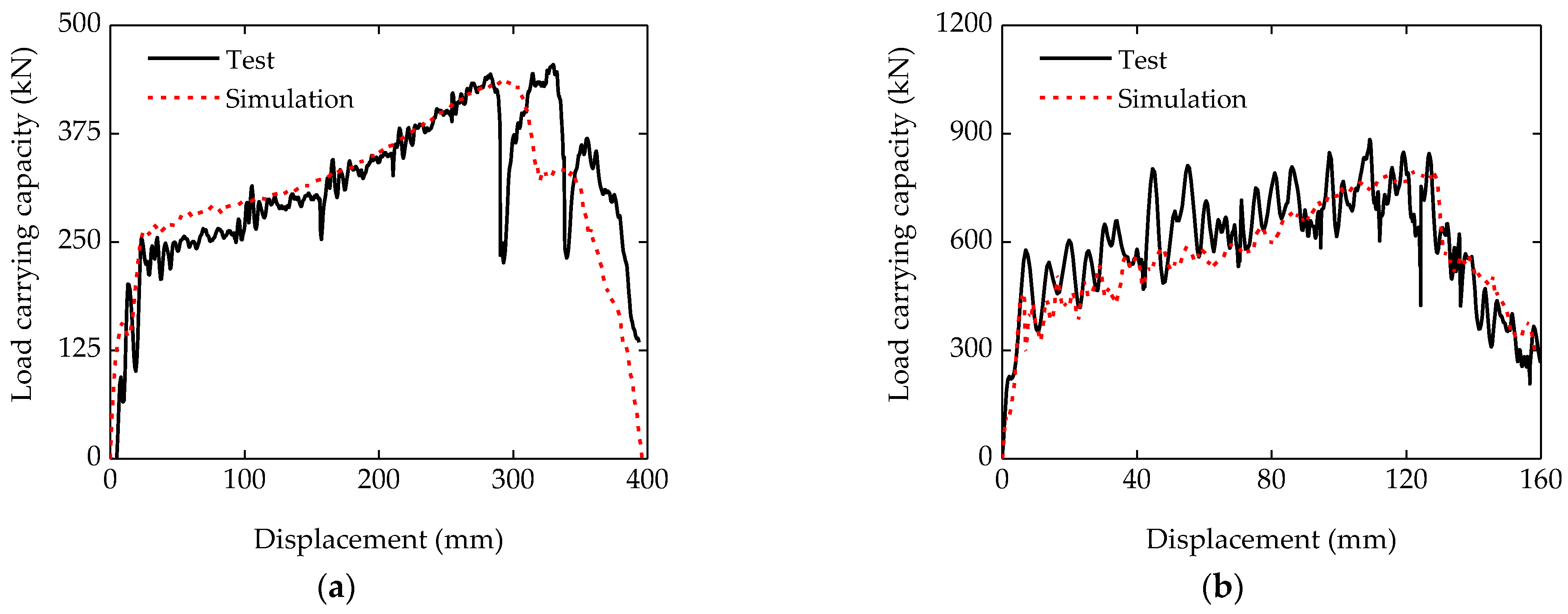
2.3. Validation of Finite Element Models
3. Assessment Method of Impact Resistance
- 1.
- Determining the load-carrying capacity–displacement curves:
- The load-carrying capacity–displacement (R-u) curves of steel-framed subassembly under falling debris impact scenarios can be obtained through experimental tests, numerical simulations, or a simplified approach [35].
- 2.
- Modifying the load-carrying capacity–displacement curves:
- After determining the R-u curve of the subassembly, its coordinate axes need to be offset to account for the deformation of the impacted subassemblies caused by their self-gravitational load G after the collision, as shown in Figure 5. Thus, the resulting offset R’-u’ curve will be used in the subsequent impact resistance assessments.
- 3.
- Initializing the impact resistance curve (R’d-u’d curve):
- Set R’d,i = 0, u’d,i = 0, i = 0, and Ea,i = 0, where parameter i is the step number and Ea is the energy absorbed by the steel-framed subassembly. Determine the displacement increment δi from step i to step i+1.
- 4.
- Determine the modified load-carrying capacity R’i+1 at displacement u’d,i+1:
- Calculate u’d,i+1 = u’d,i + δi. Determine R’i+1 from the modified load-carrying capacity–displacement R’-u’ curve based on u’d,i+1.
- 5.
- Determine the impact resistance R’d,i+1 at displacement u’d,i+1:
- Calculate the energy absorbed by subassembly Ea,i+1, i.e., the area enclosed by the R’-u’ curve and the coordinate axes between u’d = 0 to u’d,i+1: Ea,i+1 = Ea,i + (R’i+1−R’i)δi/2. Determine the current impact resistance R’d,i+1 = αEa,i+1/(αu’d,i+1+h), where α is a parameter depending on the assumed impact load distribution on the subassembly with a value of 1.0, and h is the falling height of drop hammer.
- 6.
- Obtain the entire R’d-u’d curve:
- If there are more points in the R’-u’ curve, set i = i + 1 and repeat Steps 3 to 5 until a complete impact resistance curve is obtained.
4. Impact Resistance Assessment Based on Drop-Hammer Impact Tests
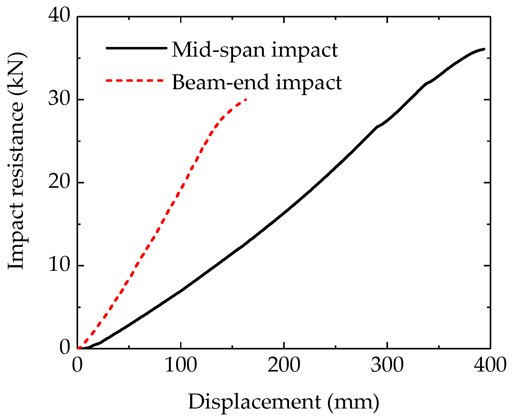
4.1. Effect of Impact Locations
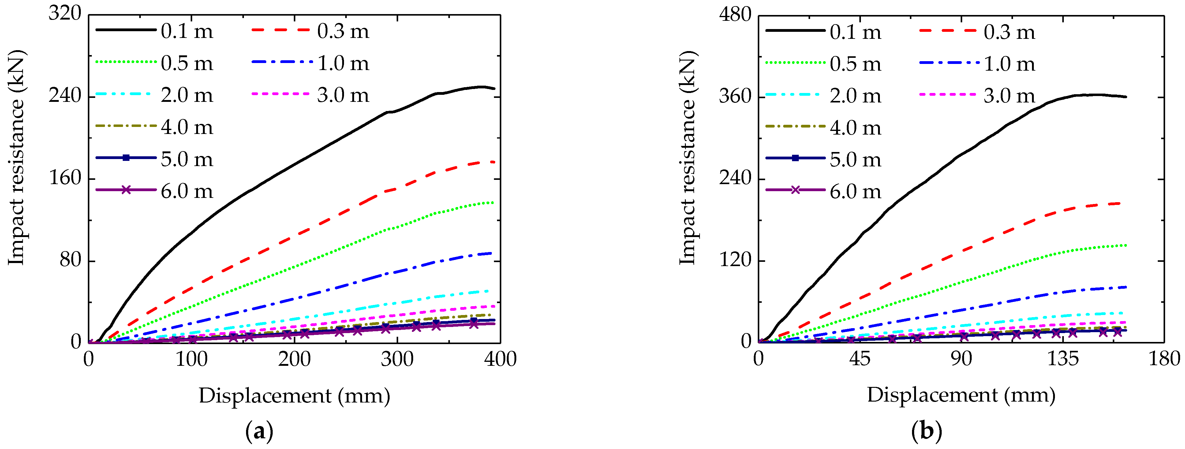
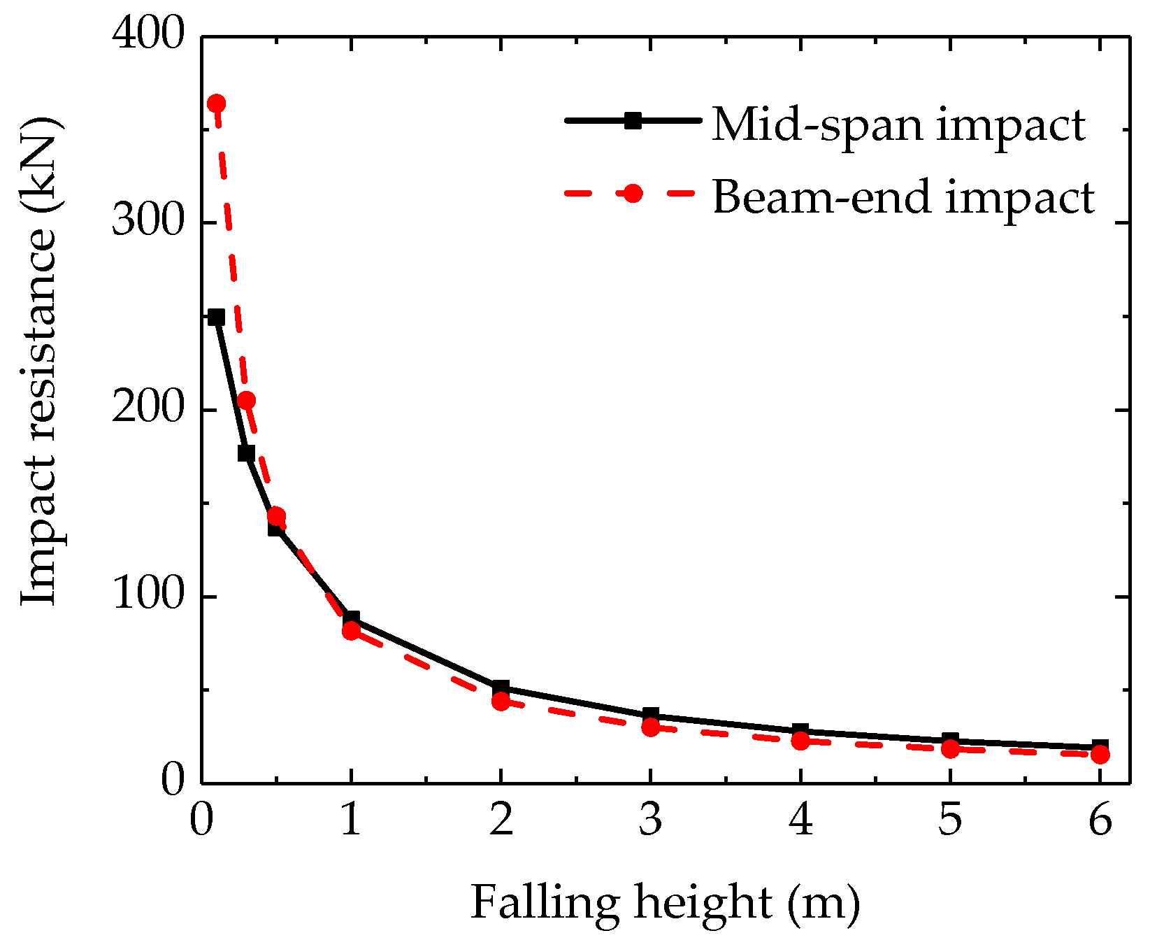
4.2. Effect of Falling Height
5. Impact Resistance Assessment Based on Numerical Simulations
5.1. Effect of SDR on Impact Resistance
5.2. Impact Load-Resisting Mechanism
5.2.1. Mid-Span Impact Scenario
5.2.2. Beam-End Impact Scenario
5.3. Effect of Catenary Action on Impact Resistance
6. Conclusions
- (1)
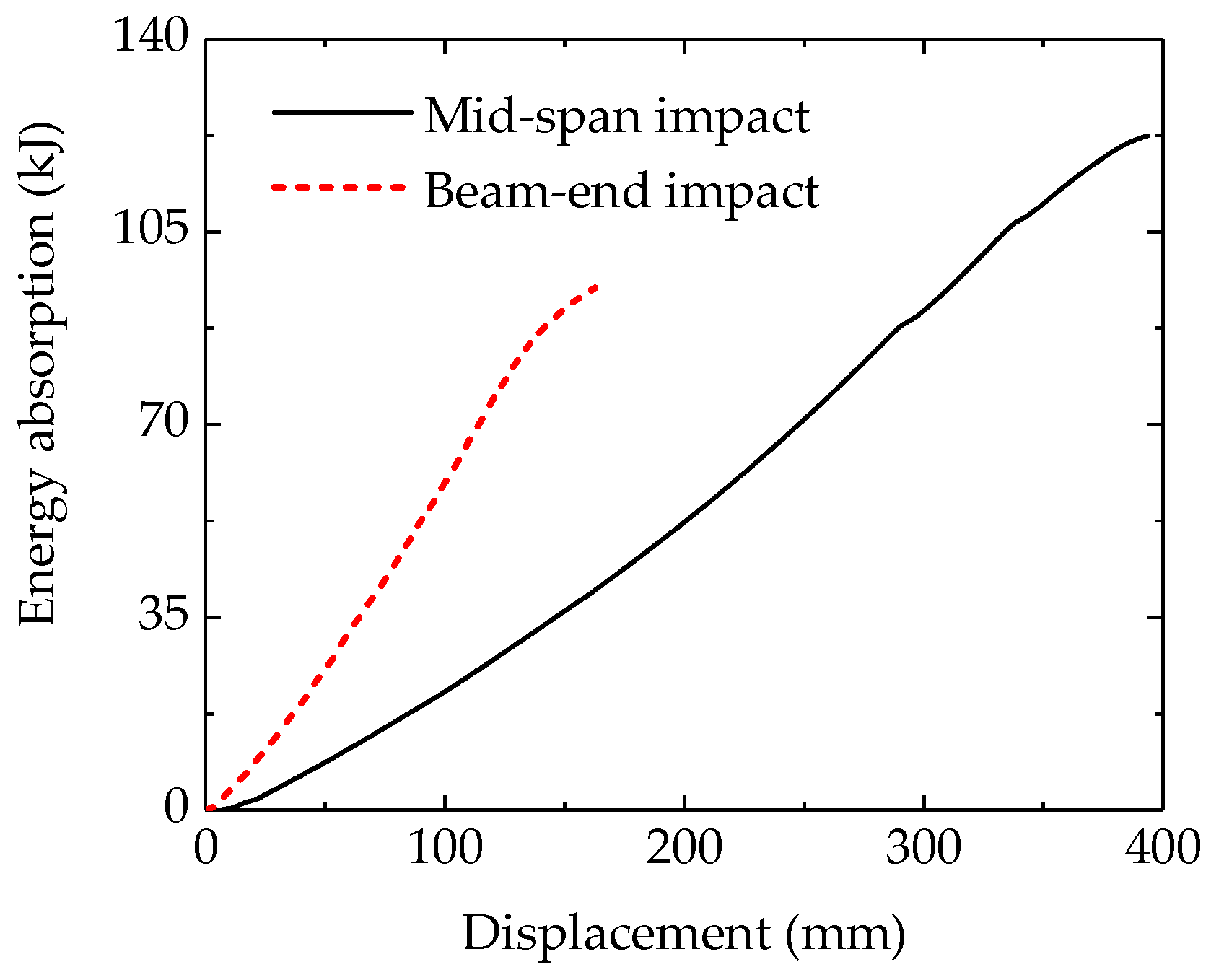
- Impact Location Effects: Although the beam-end impact scenarios exhibit higher peak load-carrying capacities, the mid-span impact scenarios result in superior impact resistance when the falling height exceeds 1.0 m. This is attributed to the greater plastic deformation and energy absorption capacity of specimens under mid-span impacts, whereas beam-end impacts are constrained by joint stiffness, limiting the deformation.
- (2)
- Falling Height Effects: The impact resistance decreases with an increasing falling height, with the reduction ratio exceeding the theoretical 50% due to the additional gravitational potential energy conversion during post-impact deformation. For falling heights ≤ 0.5 m, beam-end impacts show better resistance, while mid-span impacts are advantageous for heights ≥ 1.0 m.
- (3)
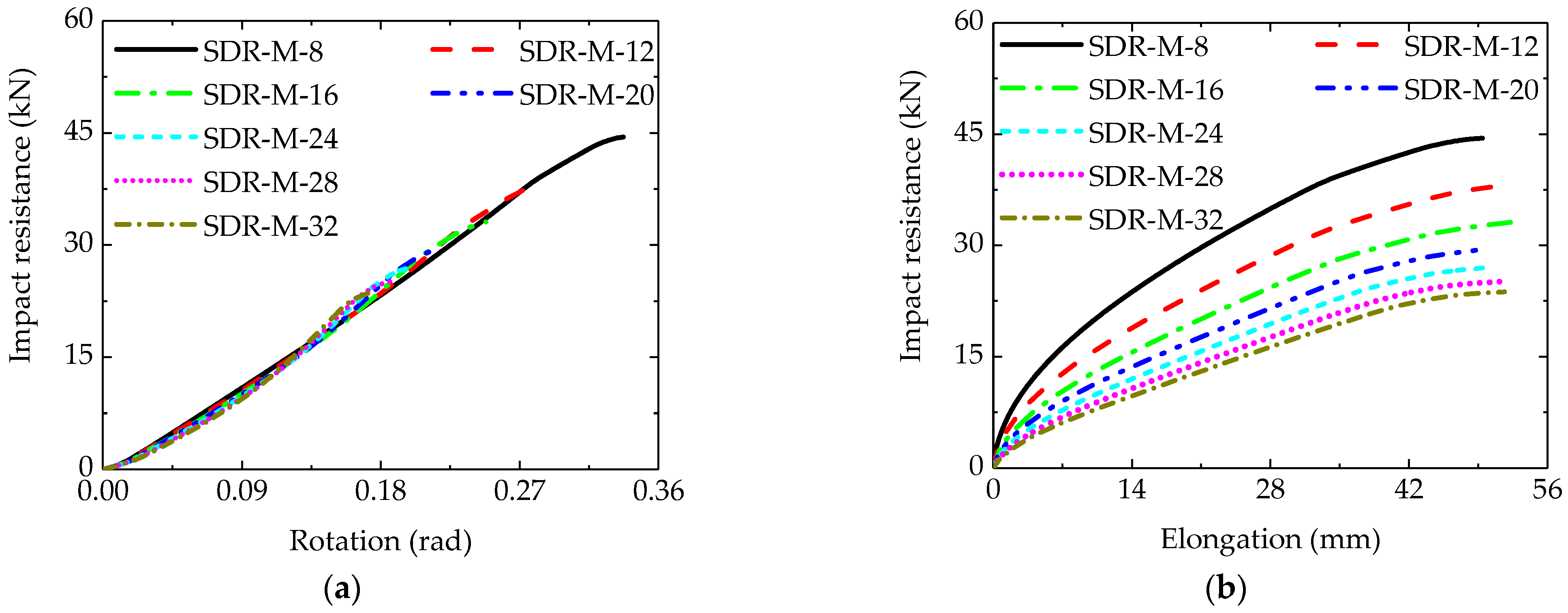
- SDR Effects: Under a mid-span impact, smaller SDRs (stiffer beams) lead to steeper impact resistance–displacement curves and a higher peak resistance, while larger SDRs require greater displacements for energy absorption. Under a beam-end impact, the SDR has a weaker influence, with the curves overlapping initially and smaller SDRs showing slightly higher peak resistances.
- (4)
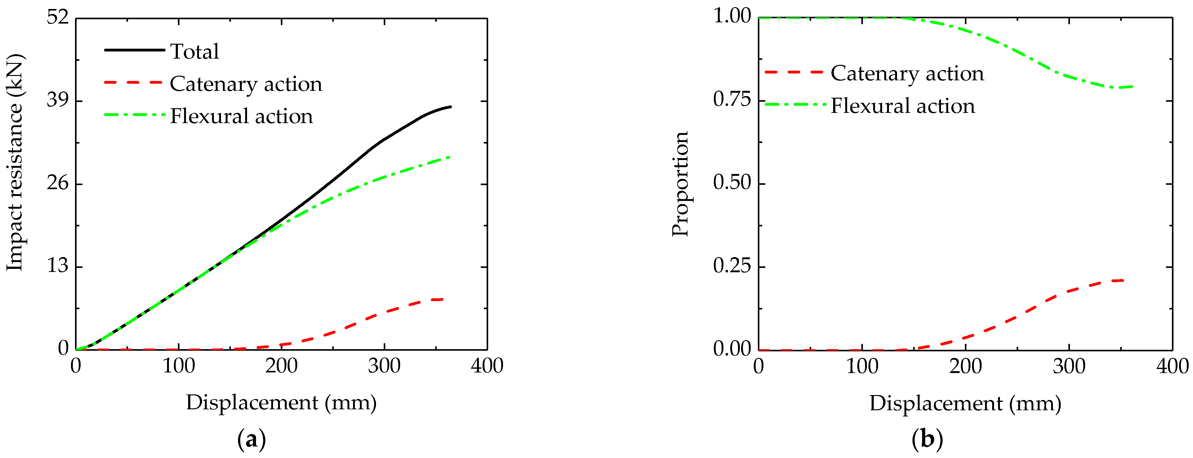
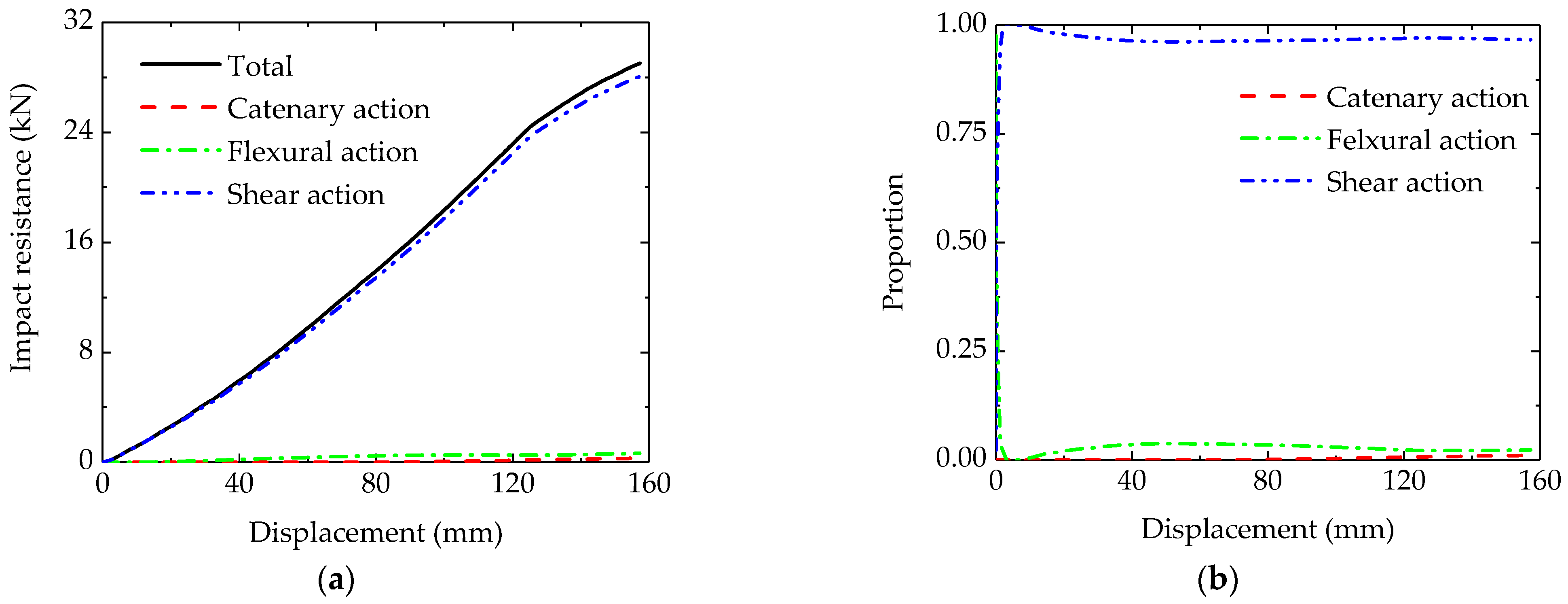
- Load-Resisting Mechanisms: Flexural action dominates the initial deformation, with catenary action contributing significantly under mid-span impacts (especially for large displacements). Shear action is the primary resistance under beam-end impacts, overshadowing the flexural and catenary effects.
- (5)
- Design suggestions: In progressive collapse-resistant design, the structural parameters should be considered differentially according to the potential impact locations. For areas prone to mid-span impacts, the SDR of steel beams should be reasonably controlled, with priority given to smaller SDRs to enhance the initial stiffness. Meanwhile, the contribution of catenary action in the large deformation stage can be utilized to improve the impact resistance. For the parts with a higher risk of beam-end impact, emphasis should be placed on strengthening the shear performance of beam–column connections, and the dominance of shear action on the impact resistance dominated should be ensured through optimizing the connection configurations. In addition, the structural scheme needs to be adjusted in combination with the expected falling height of debris. For low-height impact scenarios, focus should be placed on connection stiffness to reduce the additional energy input caused by deformation; for high-height impact scenarios, the potential of deformation-based energy absorption should be fully exerted by improving the structural ductility. Ultimately, the anti-collapse performance of steel-framed structures under different impact conditions can be optimized.
Author Contributions
Funding
Data Availability Statement
Conflicts of Interest
References
- Adam, J.M.; Parisi, F.; Sagaseta, J.; Lu, X. Research and practice on progressive collapse and robustness of building structures in the 21st century. Eng. Struct. 2018, 173, 122–149. [Google Scholar] [CrossRef]
- T/CECS392-2021; Standard for Anti-Collapse Design of Building Structures. China Association for Engineering Construction Standardization, China Plan Press: Beijing, China, 2021.
- UFC 4-023-03; Design of Buildings to Resist Progressive Collapse, Unified Facilities Criteria. Department of Defense (DoD): Washington, DC, USA, 2024.
- General Services Administration (GSA). Alternate Path Analysis & Design Guidelines for Progressive Collapse Resistance; General Services Administration (GSA): Washington, DC, USA, 2016. [Google Scholar]
- Kiakojouri, F.; Biagi, V.D.; Chiaia, B.; Sheidaii, M.R. Progressive collapse of framed building structures: Current knowledge and future prospects. Eng. Struct. 2020, 206, 110061. [Google Scholar] [CrossRef]
- Wang, H.; Tan, K.H.; Yang, B. Experimental tests of steel frames with different beam-column connections under falling debris impact. J. Struct. Eng. 2020, 146, 04019183. [Google Scholar] [CrossRef]
- Lu, X.; Jiang, J. Dynamic finite element simulation for the collapse of world trade center. China Civ. Eng. J. 2001, 34, 8–10. [Google Scholar]
- Omika, Y.; Fukuzawa, E.; Koshika, N.; Morikawa, H.; Fukuda, R. Structural responses of world trade center under aircraft attacks. J. Struct. Eng. 2005, 131, 6–15. [Google Scholar] [CrossRef]
- Kaewkulchai, G.; Williamson, E.B. Modeling the impact of failed members for progressive collapse analysis of frame structures. J. Perform. Constr. Facil. 2006, 20, 375–386. [Google Scholar] [CrossRef]
- Izzuddin, A.A.; Vlassis, A.G.; Elghazouli, A.Y.; Nethercot, D.A. Progressive collapse of multi-storey buildings due to sudden column loss-Part I: Simplified assessment framework. Eng. Struct. 2008, 30, 1308–1318. [Google Scholar] [CrossRef]
- Vlassis, A.G.; Izzuddin, B.A.; Elghazouli, A.Y.; Nethercot, D.A. Progressive collapse of multi-storey buildings due to sudden column loss-Part II: Application. Eng. Struct. 2008, 30, 1424–1438. [Google Scholar] [CrossRef]
- Vlassis, A.G.; Izzuddin, B.A.; Elghazouli, A.Y.; Nethercot, D.A. Progressive collapse of multi-storey buildings due to failed floor impact. Eng. Struct. 2009, 31, 1522–1534. [Google Scholar] [CrossRef]
- Jawdhari, A.; Orton, S.; Izzuddin, B.; Cormie, D. Dynamic debris loading in flat plate and steel framed buildings. In Proceedings of the Structures Conference 2018: Blast, Impact Loading, and Response; and Research and Education, Fort Worth, TX, USA, 19–21 April 2018. [Google Scholar]
- Haas, K.; Bychkowski, M.; Marjanishvili, S. A review of analysis methods for falling debris resulting from structural collapse. In Proceedings of the Structures Conference 2018: Blast, Impact Loading, and Response; and Research and Education, Fort Worth, TX, USA, 19–21 April 2018. [Google Scholar]
- Huo, J.; Zhang, J.; Liu, A.; Fu, E. Dynamic behaviour and catenary action of axially-restrained steel beam under impact loading. Structures 2017, 11, 84–96. [Google Scholar] [CrossRef]
- D’Antimo, M.; Latour, M.; Rizzano, G.; Demonceau, J.F. Experimental and numerical assessment of steel beams under impact loadings. J. Constr. Steel Res. 2019, 158, 230–247. [Google Scholar] [CrossRef]
- Luo, C.; Wang, F.; Chen, H.; Chen, L.; Fu, C.; Chen, Y. Castellated steel beams under impact load. J. Constr. Steel Res. 2022, 196, 107394. [Google Scholar] [CrossRef]
- Huang, J.; Fu, C.; Yu, Z.; Huang, Y.; Cai, H.; Chen, H.; Luo, C. Impact resistance performance and simplified calculation method of web-opened steel beams under impact loads. J. Constr. Steel Res. 2024, 218, 108688. [Google Scholar] [CrossRef]
- Al-Rifaie, A.; Al-Husainy, A.S.; Al-Mansoori, T.; Shubbar, A. Flexural impact resistance of steel beams with rectangular web openings. Case Stud. Constr. Mat. 2021, 14, e00509. [Google Scholar] [CrossRef]
- Wang, Y.; Sah, T.P.; Lu, J.; Zhai, X. Behavior of steel-concrete steel sandwich beams with bolt connectors under off-center impact load. J. Constr. Steel Res. 2021, 186, 106889. [Google Scholar] [CrossRef]
- Chen, J.; Wang, Y. Finite element analysis of steel-concrete-steel sandwich beams with novel interlocked angle connectors subjected to impact loading. J. Constr. Steel Res. 2023, 207, 107977. [Google Scholar] [CrossRef]
- Qu, H.; Huo, J.; Li, A.; Jiang, Y.; Liu, Y. Experimental study on impact behaviour of steel plane tubular frames. Thin Wall. Struct. 2017, 111, 210–223. [Google Scholar] [CrossRef]
- Li, H.; Chen, W.; Pham, T.M.; Hao, H. Analytical and numerical studies on impact force profile of RC beam under drop weight impact. Int. J. Impact Eng. 2021, 147, 103743. [Google Scholar] [CrossRef]
- Wang, J.; Zhang, N.; Gao, S. Numerical study on the anti-impact performance of novel concrete-filled steel tubular joint with corrugated web and cover plates. J. Constr. Steel Res. 2023, 211, 108168. [Google Scholar] [CrossRef]
- Grimsmo, E.L.; Clausen, A.H.; Langseth, M.; Aalberg, A. An experimental study of static and dynamic behaviour of bolted end-plate joints of steel. Int. J. Impact Eng. 2015, 85, 132–145. [Google Scholar] [CrossRef]
- Kukla, D.; Kozlowski, A.; Miller, B.; Ziaja, D.; Nykiel, D. Experimental investigation of steel beam-to-column end-plate joints under static and impact loading. J. Constr. Steel Res. 2024, 212, 108241. [Google Scholar] [CrossRef]
- Wang, H.; Huo, J.; Liu, Y.; Elchalakani, M.; Zhu, Z. Dynamic performance of composite beam-column connections subjected to impact loadings. J. Constr. Steel Res. 2021, 178, 106498. [Google Scholar] [CrossRef]
- Chen, K.; Yang, B.; Tan, K.H. Behaviour of composite beam-column joint with fin plate connection subjected to impact loads. Eng. Struct. 2022, 273, 115143. [Google Scholar] [CrossRef]
- Chen, Y.; Huo, J.; Chen, W.; Hao, H.; Elghazouli, A.Y. Experimental and numerical assessment of welded steel beam-column connections under impact loading. J. Constr. Steel Res. 2020, 172, 106368. [Google Scholar] [CrossRef]
- Cui, P.; Liu, Y.; Chen, F.; Huo, J. Dynamic behaviour of square tubular T-joints under impact loadings. J. Constr. Steel Res. 2018, 143, 208–222. [Google Scholar] [CrossRef]
- Li, H.; Chen, W.; Huang, Z.; Hao, H.; Ngo, T.T.; Pham, T.M. Influence of various impact scenarios on the dynamic performance of concrete beam-column joints. Int. J. Impact Eng. 2022, 167, 104284. [Google Scholar] [CrossRef]
- Jin, L.; Li, X.; Zhang, R.; Du, X. Failure mechanism and dynamic response of reinforced concrete joints under impact load acting on beam ends. Int. J. Impact Eng. 2024, 185, 104863. [Google Scholar] [CrossRef]
- Wang, H.; Yang, B.; Zhou, X.; Kang, S. Numerical analyses on steel beams with fin-plate connections subjected to impact loads. J. Constr. Steel Res. 2016, 124, 101–112. [Google Scholar] [CrossRef]
- Wang, H.; Tan, K.H.; Yang, B. Impact resistance of steel frames with different beam-column connections subject to falling-floor impact on various locations. J. Struct. Eng. 2021, 147, 04021017. [Google Scholar] [CrossRef]
- Wang, H.; Yang, B.; Chen, K.; Elchalakani, M. Parametric analysis and simplified approach for steel-framed subassemblies with reverse channel connection under falling-debris impact. Eng. Struct. 2020, 225, 111263. [Google Scholar] [CrossRef]
- Chen, K.; Wang, D.; Yang, B.; Lin, X.; Elchalakani, M. Parametric study on composite beam with various connections under mid-span impact scenarios. Eng. Struct. 2022, 268, 114776. [Google Scholar] [CrossRef]
- Wang, J.; Li, H.; Gao, S. Analysis and evaluation on residual impact resistance of CFST composite frames under column removal scenario. Thin Wall. Struct. 2025, 206, 112624. [Google Scholar] [CrossRef]
- Wang, Y.; Xue, L. Experimental study of moment-rotation characteristics of reverse channel connections to tubular columns. J. Constr. Steel Res. 2013, 85, 92–104. [Google Scholar] [CrossRef]
- BS 4-1: 2005; Structural Steel Sections—Part 1: Specification for Hot-Rolled Sections. British Standards Institution: London, UK, 2005.
- BS EN 10025-2: 2004; Hot Rolled Products of Structural Steels—Part 2: Technical Delivery Conditions for Non-Alloy Structural Steels. British Standards Institution: London, UK, 2004.
- BS EN ISO 377-2013; Steel and Steel Products—Location and Preparation of Samples and Tests Pieces for Mechanical Testing. British Standards Institution: London, UK, 2013.
- ISO 6892-1: 2016; Metallic Materials—Tensile Testing. Part 1: Method of Test at Room Temperature; British Standards Institution: London, UK, 2016.






| Component | Yield Stress (MPa) | Ultimate Stress (MPa) | Elongation 1 |
|---|---|---|---|
| Column flange | 375 | 556 | 0.29 |
| Column web | 412 | 574 | 0.29 |
| Beam flange | 370 | 536 | 0.33 |
| Beam web | 386 | 540 | 0.32 |
| Channel flange | 402 | 555 | 0.27 |
| Channel web | 406 | 552 | 0.33 |
| End plate | 311 | 460 | 0.36 |
| Stiffener | 395 | 553 | 0.29 |
| Impact Scenario | Peak Load-Carrying Capacity (kN) | Peak Displacement (mm) | Energy Absorption (kJ) | ||||||
|---|---|---|---|---|---|---|---|---|---|
| Test | Sim | S/T | Test | Sim | S/T | Test | Sim | S/T | |
| Mid-span impact | 454.5 | 438.1 | 0.96 | 330 | 293 | 0.89 | 121.6 | 122.9 | 1.01 |
| Beam-end impact | 883.5 | 797.0 | 0.90 | 109 | 122 | 1.12 | 94.9 | 88.9 | 0.94 |
| Impact Scenario | SDR | Peak Impact Resistance (kN) | Peak Displacement (mm) | Energy Absorption (kJ) |
|---|---|---|---|---|
| Mid-span impact | 8 | 44.44 | 290.1 | 146.2 |
| 12 | 38.12 | 364.1 | 128.2 | |
| 16 | 33.12 | 419.4 | 113.2 | |
| 20 | 29.43 | 454.8 | 101.7 | |
| 24 | 27.02 | 501.9 | 94.62 | |
| 28 | 25.19 | 550.4 | 89.43 | |
| 32 | 23.74 | 587.0 | 85.15 | |
| Beam-end impact | 8 | 30.59 | 156.7 | 96.57 |
| 10 | 29.69 | 157.1 | 93.75 | |
| 12 | 29.01 | 157.2 | 91.60 | |
| 16 | 28.08 | 160.0 | 88.73 | |
| 24 | 28.03 | 162.6 | 88.64 | |
| 32 | 27.86 | 162.6 | 88.10 |
| Impact Scenario | SDR | |||||||
|---|---|---|---|---|---|---|---|---|
| 8 | 10 | 12 | 16 | 20 | 24 | 28 | 32 | |
| Mid-span impact | 22.22 | 20.64 * | 19.06 | 16.56 | 14.72 | 13.51 | 12.60 | 11.87 |
| Beam-end impact | 4.87 | 3.57 | 2.79 | 1.91 | 1.54 * | 1.16 | 0.99 * | 0.82 |
| Impact Scenario | SDR | Peak Impact Resistance Considering Catenary Action (kN) | Peak Impact Resistance Without Catenary Action (kN) | Peak Impact Resistance Increase Caused by Catenary Action |
|---|---|---|---|---|
| Mid-span impact | 8 | 44.44 | 37.26 | 19.3% |
| 12 | 38.11 | 30.25 | 26.0% | |
| 16 | 33.12 | 24.72 | 34.0% | |
| 20 | 29.43 | 20.67 | 42.4% | |
| 24 | 27.02 | 17.87 | 51.2% | |
| 28 | 25.19 | 15.97 | 57.7% | |
| 32 | 23.74 | 14.24 | 66.7% | |
| Beam-end impact | 8 | 30.59 | 30.28 | 1.02% |
| 10 | 29.69 | 29.37 | 1.09% | |
| 12 | 29.01 | 28.71 | 1.04% | |
| 16 | 28.08 | 27.83 | 0.90% | |
| 24 | 28.03 | 27.81 | 0.79% | |
| 32 | 27.86 | 27.69 | 0.61% |
Disclaimer/Publisher’s Note: The statements, opinions and data contained in all publications are solely those of the individual author(s) and contributor(s) and not of MDPI and/or the editor(s). MDPI and/or the editor(s) disclaim responsibility for any injury to people or property resulting from any ideas, methods, instructions or products referred to in the content. |
© 2025 by the authors. Licensee MDPI, Basel, Switzerland. This article is an open access article distributed under the terms and conditions of the Creative Commons Attribution (CC BY) license (https://creativecommons.org/licenses/by/4.0/).
Share and Cite
Wang, H.; Zhao, L.; Zhang, Q.; Wang, J.; Xie, Y.; Gryniewicz, M. Assessment of Steel-Framed Subassemblies with Extended Reverse Channel Connections Under Falling Debris Impact. Buildings 2025, 15, 3230. https://doi.org/10.3390/buildings15173230
Wang H, Zhao L, Zhang Q, Wang J, Xie Y, Gryniewicz M. Assessment of Steel-Framed Subassemblies with Extended Reverse Channel Connections Under Falling Debris Impact. Buildings. 2025; 15(17):3230. https://doi.org/10.3390/buildings15173230
Chicago/Turabian StyleWang, Hao, Lijie Zhao, Qi Zhang, Jianshuo Wang, Yongping Xie, and Marcin Gryniewicz. 2025. "Assessment of Steel-Framed Subassemblies with Extended Reverse Channel Connections Under Falling Debris Impact" Buildings 15, no. 17: 3230. https://doi.org/10.3390/buildings15173230
APA StyleWang, H., Zhao, L., Zhang, Q., Wang, J., Xie, Y., & Gryniewicz, M. (2025). Assessment of Steel-Framed Subassemblies with Extended Reverse Channel Connections Under Falling Debris Impact. Buildings, 15(17), 3230. https://doi.org/10.3390/buildings15173230


