Article

SMA-Activated Double-Stage Yielding BRB: Experimental and FEM Insights

1
Institute of Advanced Engineering Structures, Zhejiang University, Hangzhou 310058, China
2
Center for Balance Architecture, Zhejiang University, Hangzhou 310007, China
3
The Architectural Design & Research Institute of Zhejiang University Co., Ltd., Hangzhou 310007, China
4
Zhejiang Building—Tech Energy Dissipation Technology Co., Ltd., Shaoxing 312030, China
5
Zhejiang Province Institute of Architectural Design and Research, Hangzhou 310006, China
*
Author to whom correspondence should be addressed.
Buildings 2025, 15(17), 3225; https://doi.org/10.3390/buildings15173225
Submission received: 8 August 2025 / Revised: 29 August 2025 / Accepted: 3 September 2025 / Published: 7 September 2025
(This article belongs to the Section Building Structures)

Abstract

To address the limitations of traditional buckling-restrained braces (BRB), which feature a single-stage yielding and inadequate energy dissipation under small earthquakes, this study proposes a novel double-stage yielding buckling-restrained brace (DSY-BRB). The proposed design integrates a sliding friction damper with shape memory alloy (SMA) bolts and conventional BRB components, enabling effective energy dissipation at small deformations and adaptive performance across varying displacement amplitudes compared with traditional BRBs. Leveraging SMA superelasticity, the DSY-BRB also exhibits self-centering capability that distinguishes it from prior DSY-BRB configurations. Experimental investigations were conducted on DSY-BRB specimens with varying core plate widths under cyclic quasi-static loading to evaluate hysteresis behavior, energy dissipation capacity, and self-centering performance. Results demonstrate that DSY-BRBs exhibit symmetric flag-shaped hysteresis curves with enhanced energy dissipation and excellent self-centering capabilities, achieving minimal residual deformation compared to traditional BRBs. Complementary finite element modeling with parametric analysis was performed to establish design guidelines for optimal double-stage buckling behavior. The findings reveal critical stiffness ratio requirements between BRB and SMA bolt-based friction damper components, providing valuable design criteria for engineering applications. This hybrid approach offers significant advantages in seismic energy dissipation and structural resilience compared to existing DSY-BRB systems.

1. Introduction

To improve the seismic performance of structures and reduce member damage, energy-dissipative dampers have been extensively developed and widely implemented [1,2,3,4,5,6,7,8,9]. Among them, the buckling-restrained brace (BRB) is frequently employed in engineering applications due to its superior hysteretic behavior, stable energy dissipation, and its ability to enhance lateral stiffness effectively [10,11,12,13,14,15,16,17,18]. However, in practical design, conventional BRBs are often required to remain elastic during multiple earthquake events to minimize low-cycle fatigue damage, which can lead to insufficient energy dissipation during minor earthquakes. Furthermore, BRBs with a single yield point are difficult to optimize for varying performance requirements across different seismic intensities.
To address the issues mentioned above, researchers have introduced the concept of double-stage yielding BRBs. For instance, Pan et al. [19] designed a series arrangement of large and small BRBs, achieving continuous staged yielding through a specialized mechanism. Li et al. [20] combined a conventional BRB with a metal tube damper, where the damper yielded during frequent earthquakes and the BRB core plate yielded during rare, severe events. Hu et al. [21] employed a variable-section BRB core plate, enabling staged yielding by locally weakening specific sections. Yang et al. [22] proposed a double-stage yielding BRB using parallel multi-core plates working together, while Wu et al. [23] achieved multi-stage yielding and progressive failure by incorporating core yielding units of differing cross-sections and lengths. Additionally, Zhai et al. [24] integrated BRBs with friction dampers, Yang et al. [25] developed an asynchronous parallel core system, and Xiong et al. [26] introduced a replaceable core plate structure—all of which have broadened the application of BRBs for staged energy dissipation. Although these studies have enriched approaches to realizing double-stage yielding BRBs, they primarily focus on energy dissipation mechanisms. Relatively few address the improvement of self-centering capabilities and the reduction in residual displacements following seismic events.
Conventional BRBs face critical limitations: to avoid low-cycle fatigue under repeated minor seismic events, they must remain largely elastic, which leads to insufficient energy dissipation during small earthquakes. Moreover, their single yield point makes it difficult to optimize performance across varying seismic intensities. Because BRBs dissipate energy primarily through plastic deformation of the core plate, over-reliance on the plastic energy dissipation of structural members under severe seismic loading frequently results in substantial residual interstory displacements, thereby impeding effective post-earthquake repair and functional recovery [27]. It has been demonstrated that when residual interstory drift exceeds 0.5%, reconstruction is often a more practical solution than repair [28,29]. These implications highlight the importance of minimizing residual deformation while maintaining robust energy dissipation. Double-stage yielding BRBs (DSY-BRBs) were proposed to alleviate the single-stage limitation and improve performance across seismic intensities; however, existing DSY-BRB research has largely overlooked structural self-centering capability. This gap highlights the need to integrate self-centering functionality into double-stage yielding systems. In response, self-centering technologies have been introduced to mitigate or eliminate residual displacements through flag-shaped hysteretic behavior [30,31,32]. Among the potential materials, superelastic SMAs are particularly well-suited for the development of self-centering dampers due to their remarkable self-centering and energy dissipation capabilities. Significant progress has been made in this domain: Han et al. [33] investigated a Ni-Ti SMA wire-based damper and systematically assessed its mechanical performance; Zhao et al. [34] developed a hybrid damper integrating SMA superelasticity with viscous energy dissipation; and Alipour et al. [35] designed a self-centering damper employing pre-stretched SMA wires. Further enhancements have been achieved by Liu et al. [36] and NourEldin et al. [37], who incorporated SMAs with additional energy-dissipating materials to optimize self-centering performance. Recent studies by Tian et al. [38], Yang et al. [39], Gur et al. [40], and Qiu et al. [41] have further expanded the applications of SMA dampers to areas such as tuned mass damping, frictional energy dissipation, and the mitigation of structural brittleness. Nevertheless, current research largely focuses on the inherent self-centering advantages of SMA dampers. In contrast, their deep integration with BRBs and the synergistic mechanisms required for enhanced multilevel energy dissipation and self-centering capabilities in structural systems remain inadequately explored.
In this study, we propose a novel approach that integrates the SMA sliding friction damper [41,42] with a BRB to develop a self-centering DSY-BRB. This innovative device utilizes the SMA sliding friction damper to provide frictional energy dissipation and self-centering capability during small to moderate earthquakes. At the same time, the BRB component is designed to yield and dissipate energy under larger seismic events. The combined action of these two mechanisms is intended to enhance the overall seismic performance of the structure significantly. To validate the effectiveness of the DSY-BRB, this study conducts structural experiments and parametric analyses focusing on its mechanical behavior, hysteretic performance, and finite element modeling. The objective is to elucidate the synergistic mechanism of graded energy dissipation and self-centering, thereby providing a theoretical foundation for its engineering application.

2. Design Principle of Double-Stage Yielding BRB

2.1. Basic Configuration

The self-centering capability of structural systems is fundamental to their post-seismic functional recovery and represents a critical performance criterion in earthquake-resistant design. Despite considerable advances in DSY-BRBs, existing research has predominantly overlooked the incorporation of self-centering mechanisms within these systems. To address this knowledge gap, this study proposes the development of a novel sliding friction damper that exploits the superelastic properties of SMAs. The proposed damper is strategically integrated with conventional BRBs to create an innovative hybrid system that synergistically combines self-centering capability with double-stage yielding behavior, thereby enhancing both seismic performance and post-earthquake functionality.
The constructional design of the SMA-activated DSY-BRB is illustrated in Figure 1a. This innovative brace consists of two primary components connected in series: the SMA sliding friction damper and the BRB. The BRB, detailed in Figure 1b, is composed of a yieldable core plate, an external coating, and a flexural restraint system. The restraint system includes a hollow steel pipe filled with mortar (or concrete) that encases the core plate. The core plate is designed to primarily withstand axial loads, while the restraint system provides lateral support and prevents buckling, thereby enabling the core plate to achieve yielding under both compression and tension without buckling. The unbonded coating minimizes interfacial friction, ensuring a uniform load distribution across the core plate. This prevents lateral expansion damage and allows the core plate to achieve full cross-sectional yielding without significant lateral deformation. As depicted in Figure 1c, the BRB addresses the limitations of conventional braces, such as their susceptibility to buckling under compressive loads, offering stable hysteresis behavior and exceptional energy dissipation performance.
The structural design and components of the SMA sliding friction damper are shown in Figure 1d,e. The SMA bolt features threaded sections at both ends and a weakened middle section. This weakened section is preloaded by nuts on either end, focusing axial deformation within this region. The damper’s center plate and cap plate are machined with complementary inclined angles, while the center plate incorporates elongated slotted holes. As the center plate experiences forces perpendicular to the bolt, the bolt and slotted holes remain unconstrained, within the limits of the hole spacing. This configuration allows for relative sliding friction along the inclined angle between the center and cap plates, thus achieving energy dissipation.

2.2. Working Mechanism

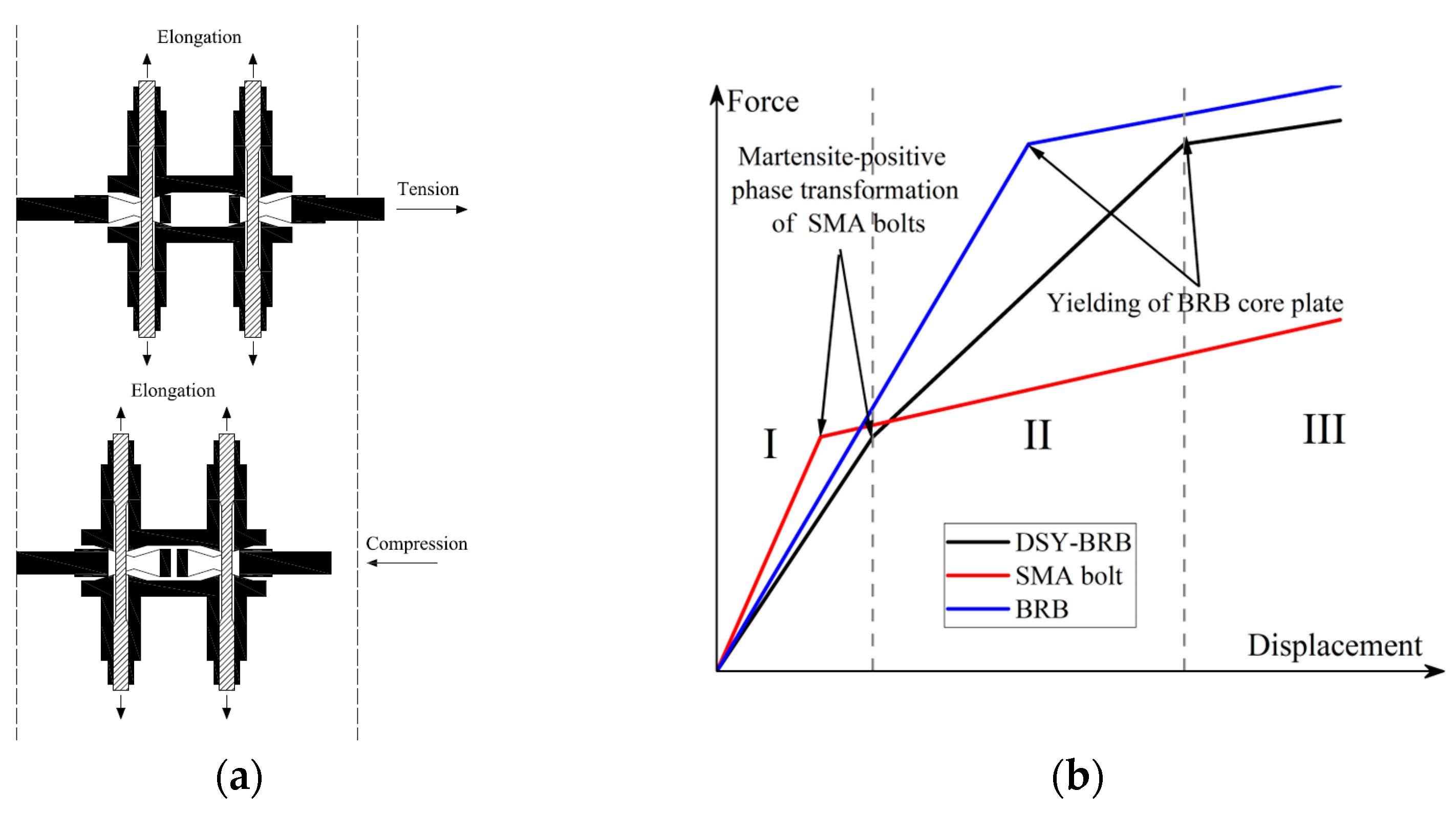
The working mechanism of the SMA sliding friction damper is illustrated in Figure 2a. When the damper is subjected to tensile or compressive forces, the center plate slides outward or inward relative to the cap plate. This sliding motion pushes the cap plate upward along the beveled surface, causing the SMA bolt to elongate. The elongation generates normal stresses on the contact surfaces between the center plate and the cap plate, resulting in friction that dissipates energy [41]. Consequently, the SMA sliding friction damper achieves energy dissipation through interfacial sliding friction and the stress-induced phase transition of the SMA bolt. Additionally, it achieves self-centering via the superelastic effect of the SMA bolt.
The SMA-activated DSY-BRB combines the SMA sliding friction damper and the conventional BRB in series, allowing the SMA sliding friction damper and the BRB core plate to work together to resist seismic loads. Based on the mechanical states of the SMA sliding damper and the core plate, the working mechanism of the DSY-BRB can be divided into three phases (Figure 2b): (1) both the SMA bolt and the core plate remain in the elastic phase; (2) the SMA bolt undergoes a stress-induced phase transition from the austenite phase to stress-induced martensite (SIM), while the core plate remains elastic; and (3) under large displacements caused by rare earthquakes, both the SMA and the BRB core plate enter the yielding stage, dissipating energy in tandem.
The unique structure and working mechanism of the DSY-BRB enable it to perform double stages of energy dissipation: during frequent or moderate earthquakes, the SMA sliding friction damper activates first, resulting in energy dissipation while the core plate of BRB remains elastic and provides lateral stiffness to the structure; during rare or extreme earthquakes, the second stage of energy dissipation is activated, as both the SMA and the core plate of BRB yield simultaneously, achieving enhanced energy dissipation. This double-stage yielding mechanism overcomes the limitation of traditional BRBs, which rely on a single yielding point and may not be effectively activated under large earthquakes due to small local displacements. Furthermore, the superelastic effect of the SMA allows the DSY-BRB to self-center, reducing the residual deformation of the structure and improving post-earthquake performance.

3. Experimental Program

3.1. Pre-Testing of SMA Phase Transition

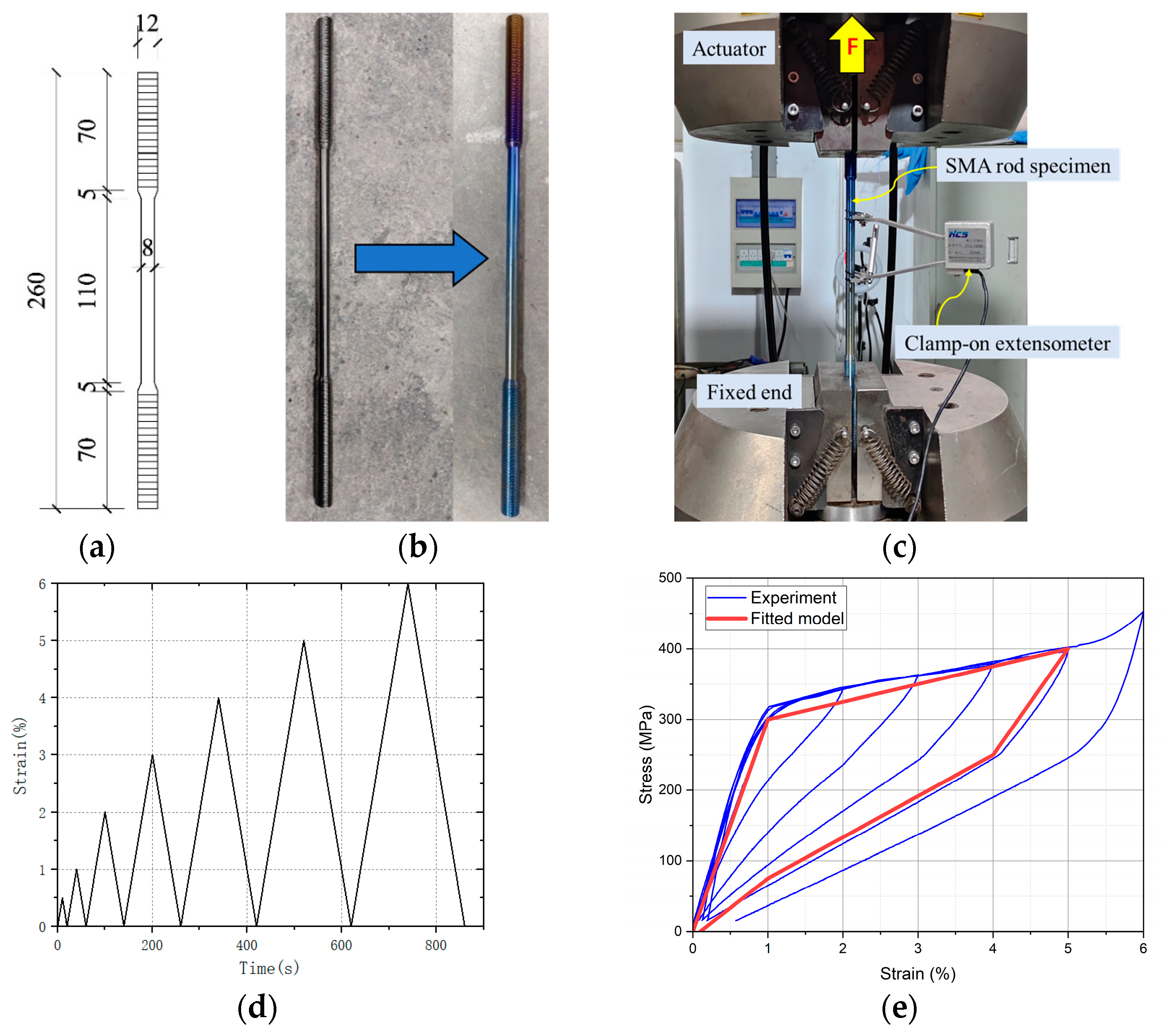
Since the DSY-BRB is designed to dissipate energy initially through the tensile yielding and self-resetting of SMA bolts, this study first investigated the mechanical properties of SMA using cyclic tensile hysteresis tests. The geometry of the SMA circular bar specimens is illustrated in Figure 3a: total length of 260 mm, end diameter of 12 mm, and a weakened central section of 110 mm length with an 8 mm diameter. To enhance and stabilize mechanical performance and superelasticity, all specimens underwent heat treatment before testing [41,42,43]. Specifically, they were heated in a muffle furnace at 400 °C for 20 min, then quenched in water [41]. The same heat treatment was applied to the SMA bolts used in subsequent damper specimens. As shown in Figure 3b, a bronze-blue oxide film formed on the specimen surfaces post-treatment, indicating adequate heat treatment.
The experimental setup and loading protocol are depicted in Figure 3c,d. A clamp-on extensometer was attached to the weakened section of each specimen to measure elongation over the marked gauge length. Loading was strain-controlled, with amplitudes of 0.5%, 1%, 2%, 3%, 4%, 5%, and 6% per cycle, applied at a strain rate of 0.05% per second. The resulting stress–strain responses are presented in Figure 3e, demonstrating the SMA’s excellent self-resetting ability and minimal residual strain after unloading. Key hysteresis parameters are summarized in Table 1, providing a basis for subsequent finite element simulations. Specifically, σMs denotes the initial stress of the forward phase transformation, σMf the final stress of the forward phase transformation, σAs the initial stress of the reverse phase transformation, σAf the final stress of the reverse phase transformation, EA the elastic modulus of austenite, and EM the elastic modulus of martensite.

3.2. Mechanical Properties of SMA Slip Friction Damper

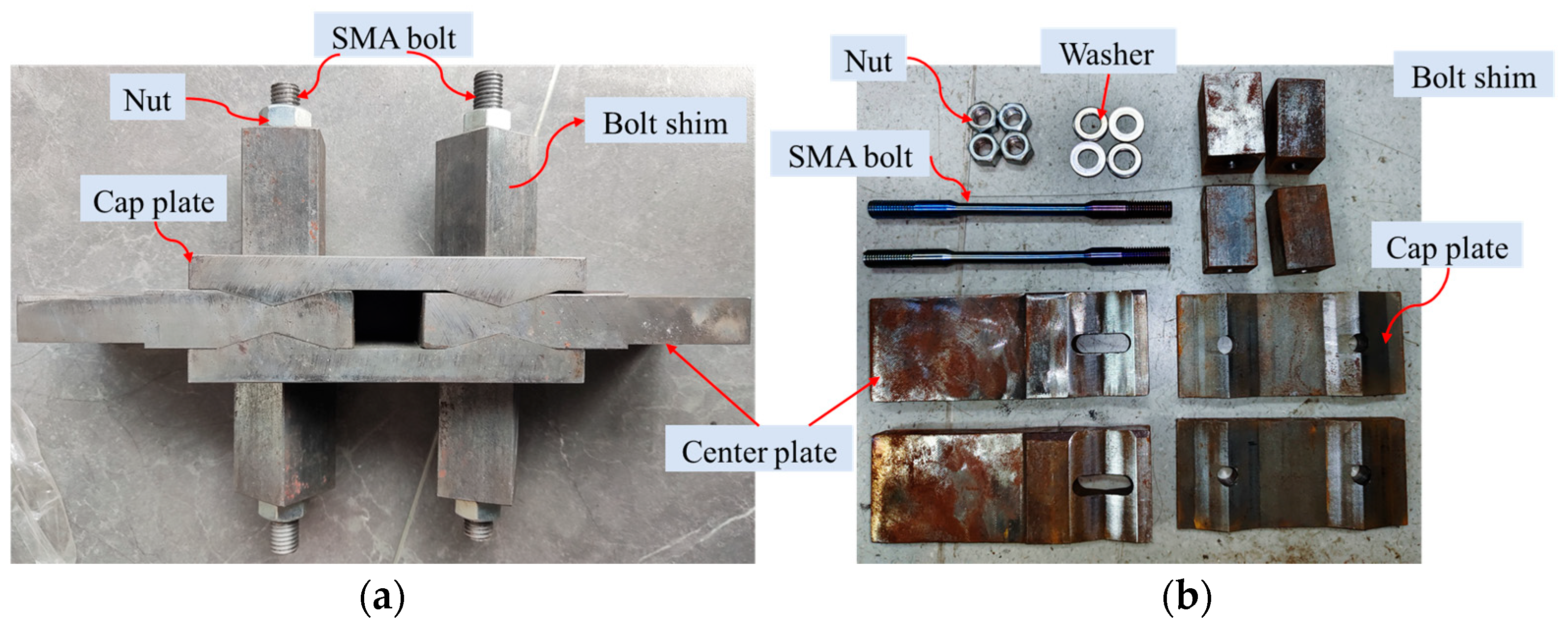
Based on the intrinsic phase transformation and mechanical characteristics of SMA, a novel SMA sliding damper specimen was designed, as illustrated in Figure 1d, and a test specimen was fabricated, as shown in Figure 4. The test setup, method, and loading protocol are detailed in Figure 5a,b, with displacement-controlled loading employed throughout the experiments. Theoretically, the peak displacement of the damper corresponds to the displacement at 5% strain in the weakened section of the SMA bolts, calculated as 13.3 mm. Accordingly, displacement amplitudes for each loading stage were determined to represent 1%, 2%, 3%, 4%, and 5% strain levels in the SMA bolts, yielding respective displacement values of 2.66 mm, 5.32 mm, 7.98 mm, 10.64 mm, and 13.3 mm. Each amplitude level was applied for two loading cycles. The loading rate was set to 8 mm/min, corresponding to a strain rate of 0.05%/s for the SMA bolts [41]. As shown in Figure 5c, the experimental results demonstrate that the specimen exhibits stable, full hysteresis loops characteristic of a flag-shaped hysteresis pattern, indicating excellent energy dissipation capability and remarkable self-centering behavior.

3.3. Mechanical Properties of SMA-Activated DSY-BRB Damper

3.3.1. Specimen Details

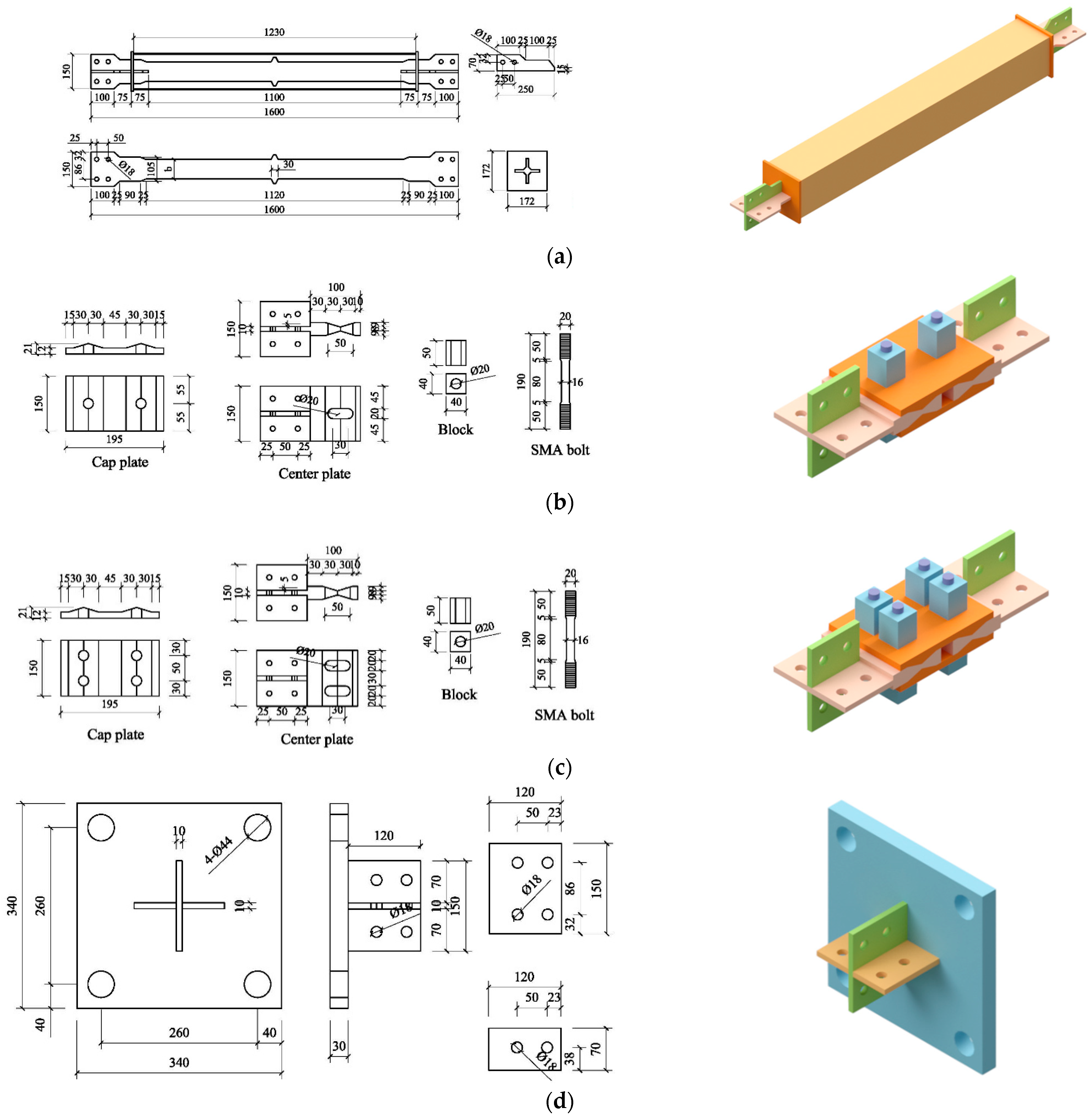
A DSY-BRB system, modeled on a prototype frame with a story height of 3.2 m and a span of 5.2 m, was used as the basis for this study. As shown in Table 2, three DSY-BRB specimens featuring 1/2 scale ratios and varying BRB core plate widths—25 mm, 55 mm, and 85 mm—were designed and labeled S1-B25, S1-B55, and S1-B85, respectively. Detailed specimen dimensions are provided in Figure 6: the overall specimen length is 1925 mm, with the BRB and the SMA sliding friction damper measuring 1600 mm and 325 mm, respectively. The SMA sliding friction damper features a friction surface inclined at 16.7°, and the center plate is equipped with 30 mm-wide slotted holes to accommodate maximum deformation requirements. Each specimen is assembled with two SMA bolts; additional dimensions for specimens with four SMA bolts, for use in parametric FEM simulations, are also presented in Figure 6. All steel components, except for the BRB core plate (fabricated from LY160 mild steel from Angang Steel Co., Ltd, Anshan, China), are constructed from Q355 steel from Nanjing Iron and Steel Co., Ltd, Nanjing, China, and C30 concrete is cast within the BRB steel casing to restrain the core plate. Bolts connect the BRB, SMA sliding damper, and flange via a connecting plate.

3.3.2. Test Setup and Loading Protocol

Pseudo-static tests were carried out at Zhejiang Building—Tech Energy Dissipation Technology Co., Ltd. The connection setup between the test specimen and the loading device is illustrated in Figure 7. Both ends of the specimen were rigidly fastened to the loading apparatus using flange plates and bolts. Axial loading was applied to the specimen via a horizontal actuator. To account for inevitable gaps at the connection interfaces, three linear variable differential transformers (LVDTs) were installed on the test rig. LVDT1 monitored the total axial displacement of the DSY-BRB and was used for controlling the loading process. LVDT2 and LVDT3 measured the displacements of the BRB section and the SMA sliding friction damper, respectively. The elongation of the SMA bolt was determined based on the displacement recorded by LVDT3 and calculated using Equation (1):
Δ = δ tan θ
where Δ represents the deformation of the damper; δ is the elongation of the SMA bolt, and θ denotes the angle between the friction surface and the horizontal plane. During loading, the displacement amplitudes were 2 mm, 2.5 mm, 5 mm, 7.5 mm, 10 mm, and 15 mm, corresponding to 1/800, 1/600, 1/300, 1/200, 1/150, and 1/100 of the BRB length, respectively. Each displacement amplitude was subjected to two loading cycles [44], and the loading rate was maintained at 0.1 mm/s throughout the test process.

3.3.3. Test Results

Fracture of the threaded portion at the end of the SMA bolt was identified as the primary failure mode for all tested specimens, as illustrated in Figure 8a. Specifically, specimen S1-B25 failed during the first cycle of tensile loading at a displacement amplitude of 7.5 mm, whereas specimens S1-B55 and S1-B85 failed during the first cycle of compressive loading at a displacement amplitude of 15 mm. The observed thread failure in SMA bolts can be attributed to two primary mechanisms. First, stress concentration effects arise from the geometric discontinuities inherent in threaded sections. Under cyclic loading conditions, these elevated stress regions become critical sites for fatigue crack initiation. Second, manufacturing-induced defects from the threading machining process can introduce surface irregularities and micro-cracks that act as stress concentrators and crack nucleation sites. These defects compromise the fatigue resistance of the bolts under repeated loading cycles, leading to premature thread failure [44]. Post-test disassembly and inspection of the BRB center plates (Figure 8b) revealed no evident yield damage in any of the core plates.
Figure 9 presents the axial force–displacement hysteresis curves for each specimen. All specimens exhibited complete, stable, and initially symmetric hysteresis loops. As the SMA bolts dissipated energy through cyclic compression and tension, the loops adopted a characteristic flag-shaped pattern, with minor residual deformations and reduced post-yield stiffness, underscoring the excellent energy dissipation and superior self-centering capability of the DSY-BRB system. During initial loading, both the BRB core plates and SMA bolts remained elastic, with the latter under preload, resulting in relatively high initial stiffness. Upon further loading, relative slip occurred between the center and cap plates, while the SMA bolts entered their phase transformation stage, resulting in reduced stiffness and increased energy dissipation through friction. With continued increases in load and displacement, the BRB core plate yielded, resulting in a further decrease in specimen stiffness and a clear double-stage yielding behavior. During unloading, the center plate of the SMA damper gradually returned to its original position, and the SMA bolts recovered their initial state. Upon complete unloading, the hysteresis curves nearly returned to the origin, confirming the specimens’ minimal residual deformation and strong self-centering capacity.
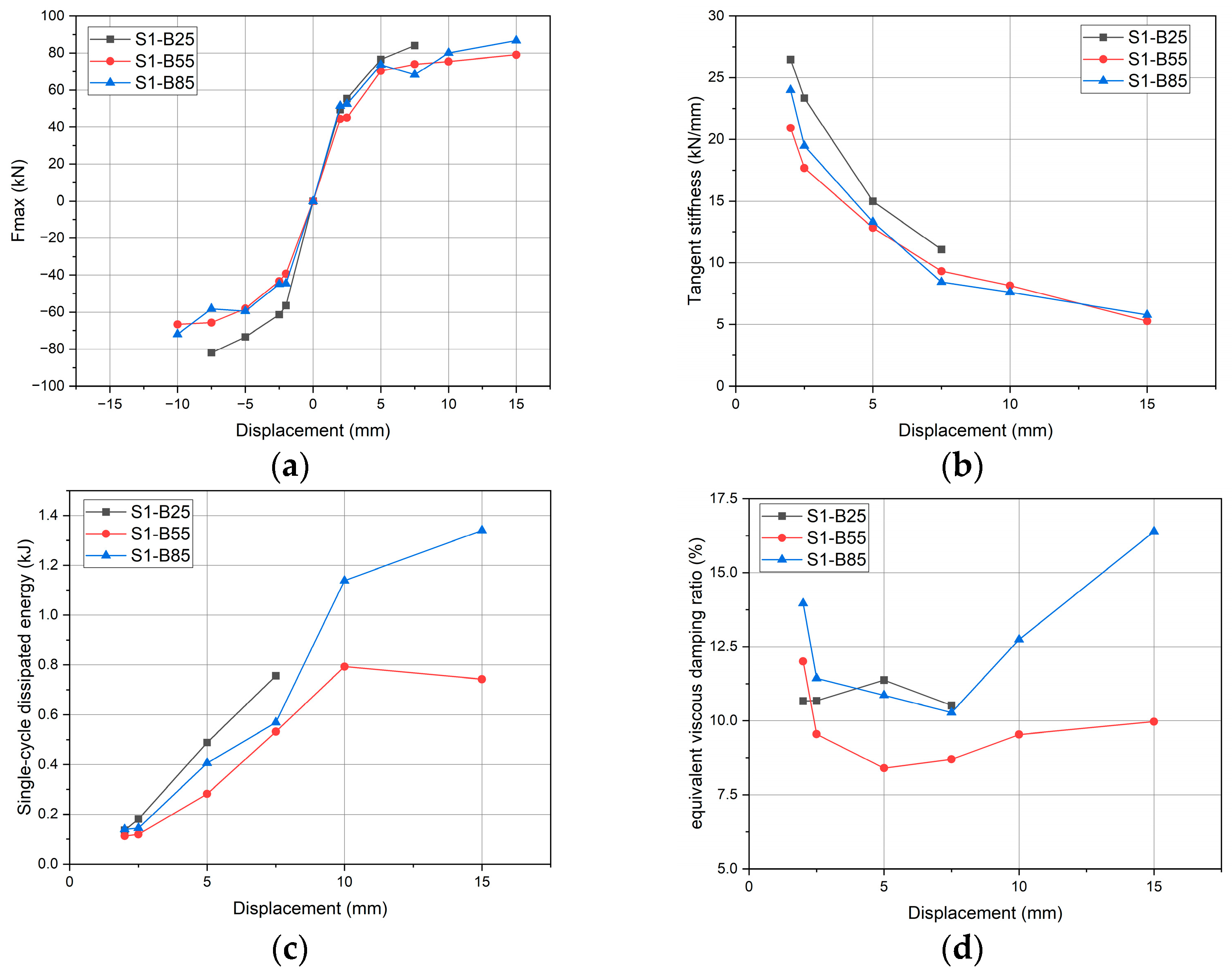
Based on the hysteresis curves for each specimen presented in Figure 9, the relationships between peak strength, tangent stiffness, dissipated energy, and equivalent viscous damping ratio and the displacement amplitude at each hysteresis loop are analyzed, as illustrated in Figure 10. As depicted in Figure 10a, the peak strength (Fmax) increases with displacement amplitude. However, as the SMA bolt undergoes forward phase transformation, the growth rate of Fmax diminishes; this trend becomes even more pronounced following the yielding of the BRB center plate, resulting in a reduced slope and manifesting a double-stage yielding behavior. The Fmax values for specimens S1-B55 and S1-B85 are nearly identical and, at larger displacement amplitudes, are lower than those observed for specimen S1-B25. Figure 10b illustrates that the initial tangent stiffness (ksec) for each specimen is approximately 25 kN/mm during the early loading stage. With increasing displacement amplitude, ksec gradually decreases—especially as the SMA bolt undergoes forward phase transformation and the BRB core plate yields—dropping to about 5 kN/mm at a displacement amplitude of 15 mm. As shown in Figure 10c, the dissipated energy (WD), represented by the area enclosed within each hysteresis loop, increases rapidly when the SMA bolts experience forward phase transformation and the BRB core plate yields. Notably, specimen S1-B85 reaches a maximum dissipated energy of 1.34 kJ at a 15 mm displacement amplitude. Finally, Figure 10d presents the equivalent viscous damping ratio (ξeq), calculated according to Equation (2):
ξ eq = W D 4 π W E
where WE denotes the strain energy. It is observed that the maximum value of ξeq reaches 16.4%. Further analysis of the above curves indicates that, during the second loading cycle, the values of peak strength (Fmax), tangent stiffness (ksec), and dissipated energy (WD) are consistently lower than those recorded during the first cycle, which may be attributed to the loosening of the SMA bolts. Table 3 summarizes the hysteretic parameters and residual displacements for each specimen at the maximum displacement amplitude. To evaluate the energy dissipation performance of the proposed DSY-BRB, Table 4 compares the damping ratio and energy dissipation capacity with typical devices reported in the literature. The results demonstrate that the DSY-BRB exhibits superior energy dissipation capacity and damping ratio compared to conventional SMA dampers. This enhanced performance is attributed to the synergistic coupling of BRB and SMA damping mechanisms, which simultaneously increases load-bearing capacity and energy dissipation efficiency.

4. Numerical Simulations

4.1. Finite Element Model

Previous experimental investigations have identified the core plate width as a key factor influencing the yield point of the DSY-BRB and highlighted its correlation with BRB stiffness. Nonetheless, the quantitative relationship between core plate width variations and the yield point of the DSY-BRB remains insufficiently understood. To assess the validity of the novel DSY-BRB configuration proposed herein, evaluate the mechanical performance of each component, and systematically examine the effects of BRB stiffness and SMA bolts on the overall behavior of the DSY-BRB; finite element modeling and simulation were conducted using ABAQUS. A total of eighteen DSY-BRB specimens were designed, employing the core plate width of the BRB and the number of SMA bolts in the SMA sliding friction damper as key variables. The stiffness of both the BRB and the SMA sliding friction dampers were calculated using theoretical approaches and subsequently normalized to the minimum stiffness ratio for comparative analysis. The detailed parameters and corresponding stiffness values for each specimen are presented in Table 5, while Figure 5 provides the precise component dimensions of the DSY-BRB assembly.
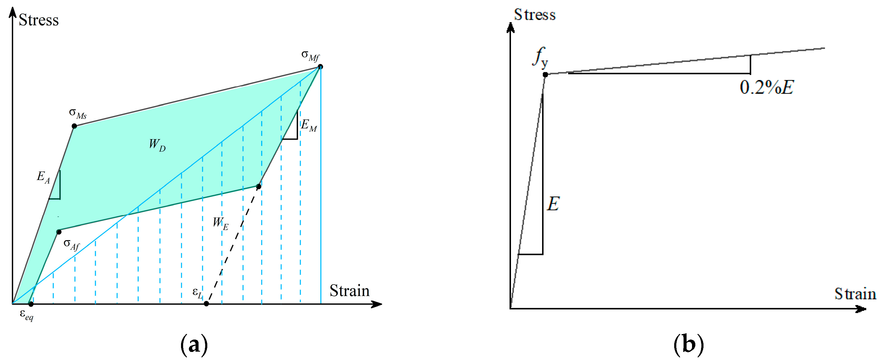
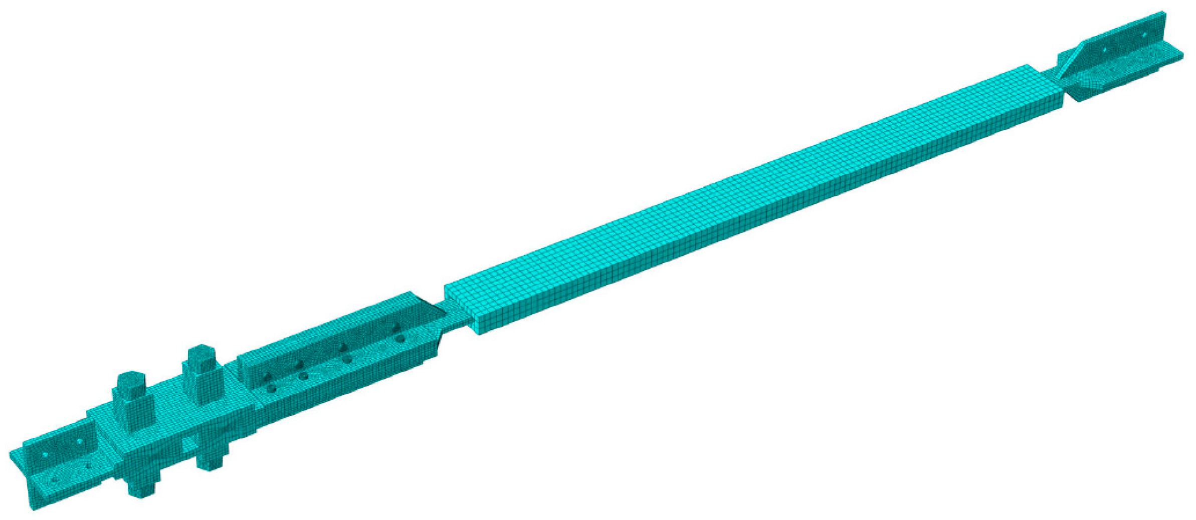
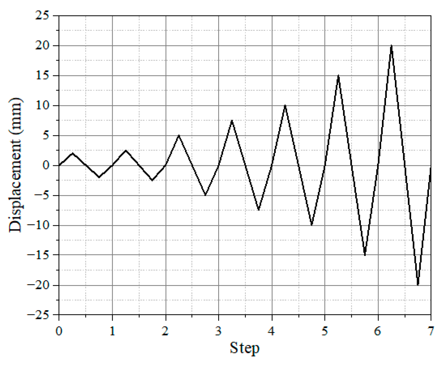
All FEM models using ABAQUS 2019 software were constructed using 8-node reduced integration hexahedral solid elements (C3D8R). The superelastic behavior of the SMA was represented with a hyperelastic constitutive model, as illustrated in Figure 11a, with material parameters sourced from Table 1. Steel components were modeled using a bilinear constitutive relationship (Figure 11b), considering an elastic modulus of 206 GPa, a Poisson’s ratio of 0.3, and incorporating 0.2% strain hardening. The yield strengths were assigned as follows: 640 MPa for nuts and connecting bolts, 140 MPa for the BRB core plates, and 235 MPa for all other steel components. Contact interactions between components were defined using a surface-to-surface formulation with “hard” normal contact behavior and penalty-based tangential behavior. A parametric sensitivity analysis was conducted to determine optimal friction coefficients through systematic variation and iterative simulations. The analysis established μ = 0.15 for the SMA sliding interface [41] and μ = 0.2 for the BRB core plate–outer shell interface, which provided the best correlation with experimental hysteretic behavior. All bolt connections and stiffener welds were simulated using the tie constraint. To replicate the loading protocol, one end of each specimen was fully fixed, while a reference point with coupled constraints at the opposite end received the prescribed displacement loading. Mesh sizing was optimized for both accuracy and computational efficiency, with settings of 3 mm for SMA bolts, 10 mm for BRB steel sleeves, and 5 mm for all other components. A sensitivity analysis was also conducted on the grid size, using the above grid size as the reference value and simulating different grid sizes to determine the optimized grid size for each component, as shown in Figure 12. All models were subjected to cyclic tension–compression loading with displacement amplitudes corresponding to 1/800, 1/600, 1/300, 1/200, 1/150, 1/100, and 1/75 of the BRB length, respectively. The detailed loading sequence is presented in Figure 13.

4.2. Verification of FEM Simulation

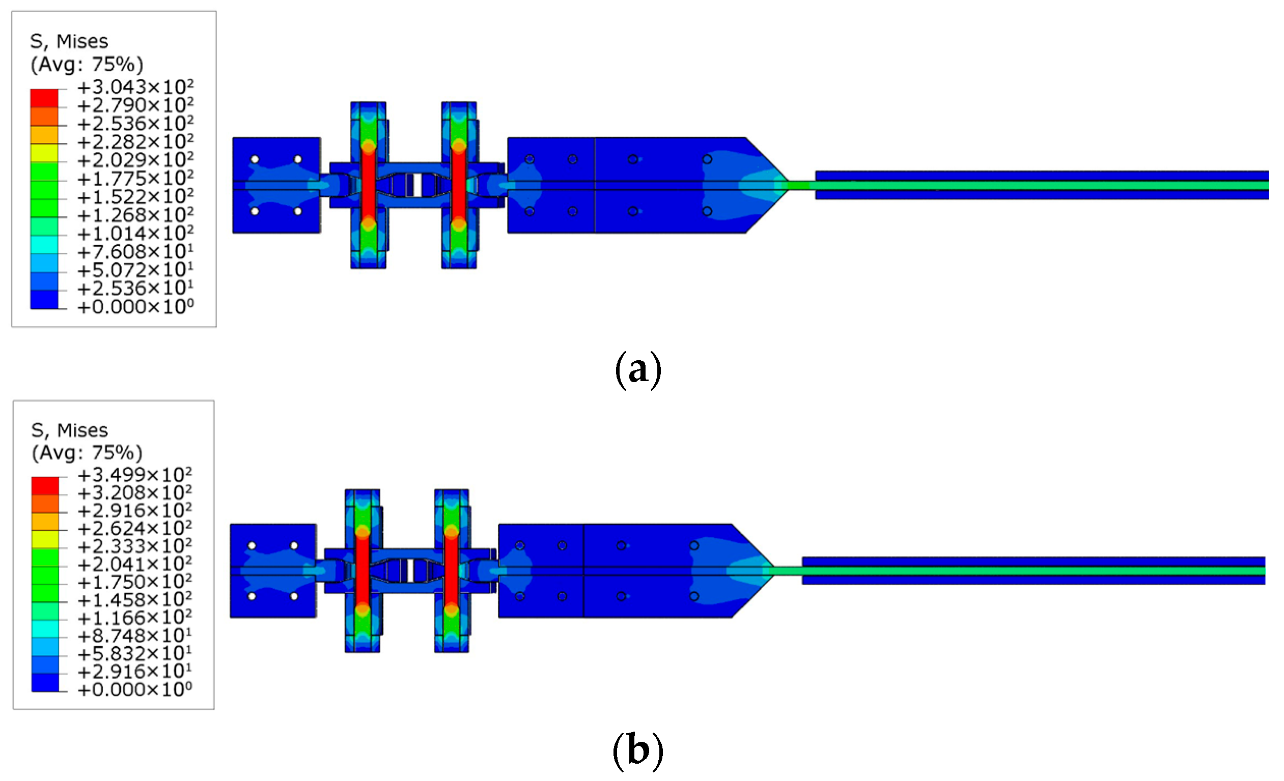
Figure 14 presents the stress distribution across the cross-section of specimen S1-B55 at the first-stage yield displacement (7.19 mm) and second-stage yield displacement (9.95 mm) under compressive loading. As shown, the stress in the midsection of the SMA bolt exceeds the initial transformation stress of 300 MPa required for the forward phase transformation. Concurrently, the stress in the BRB core plate increases from approximately 120 MPa in Figure 14a to about 150 MPa in Figure 14b, surpassing the yield strength of the core plate. These results confirm that the FEM simulation successfully captures the theoretically anticipated double-stage yielding behavior: initial yielding of the SMA bolt, followed by yielding of the core plate. At the same time, all other steel components remain within the elastic range. Furthermore, variations in the gap at the wedge of the SMA friction damper section reflect changes in relative displacement, further validating that the simulated displacement behavior aligns well with the experimental observations.
Figure 15 compares the hysteresis curves obtained from experimental testing and FEM simulations for specimens S1-B25, S1-B55, and S1-B85. For specimens S1-B55 and S1-B85, the simulated hysteresis curve shape closely matches the experimental results; however, notable discrepancies are observed in peak loads and residual displacements during each cycle. These differences are primarily due to the FEM model’s idealization of the SMA bolt connections, which do not account for bolt loosening that may occur during experimental loading, thus resulting in overestimation of peak loads and displacements in the simulations. For specimen S1-B25, the discrepancies between experimental and simulated hysteresis curves are more pronounced. This is likely due to manufacturing tolerances affecting the BRB, resulting in higher measured strengths in the experimental results compared to the simulation predictions. Table 6 compares the simulated and experimental values of peak load and secant stiffness for specimens S1-B25, S1-B55, and S1-B85, along with their corresponding errors. The results show that specimens S1-B55 and S1-B85 exhibit good agreement between simulation and experiment, with errors in both peak load and secant stiffness remaining below 12%. In contrast, specimen S1-B25 demonstrates consistently larger deviations across all loading amplitudes.

4.3. Parameter Analysis of FEM Simulation

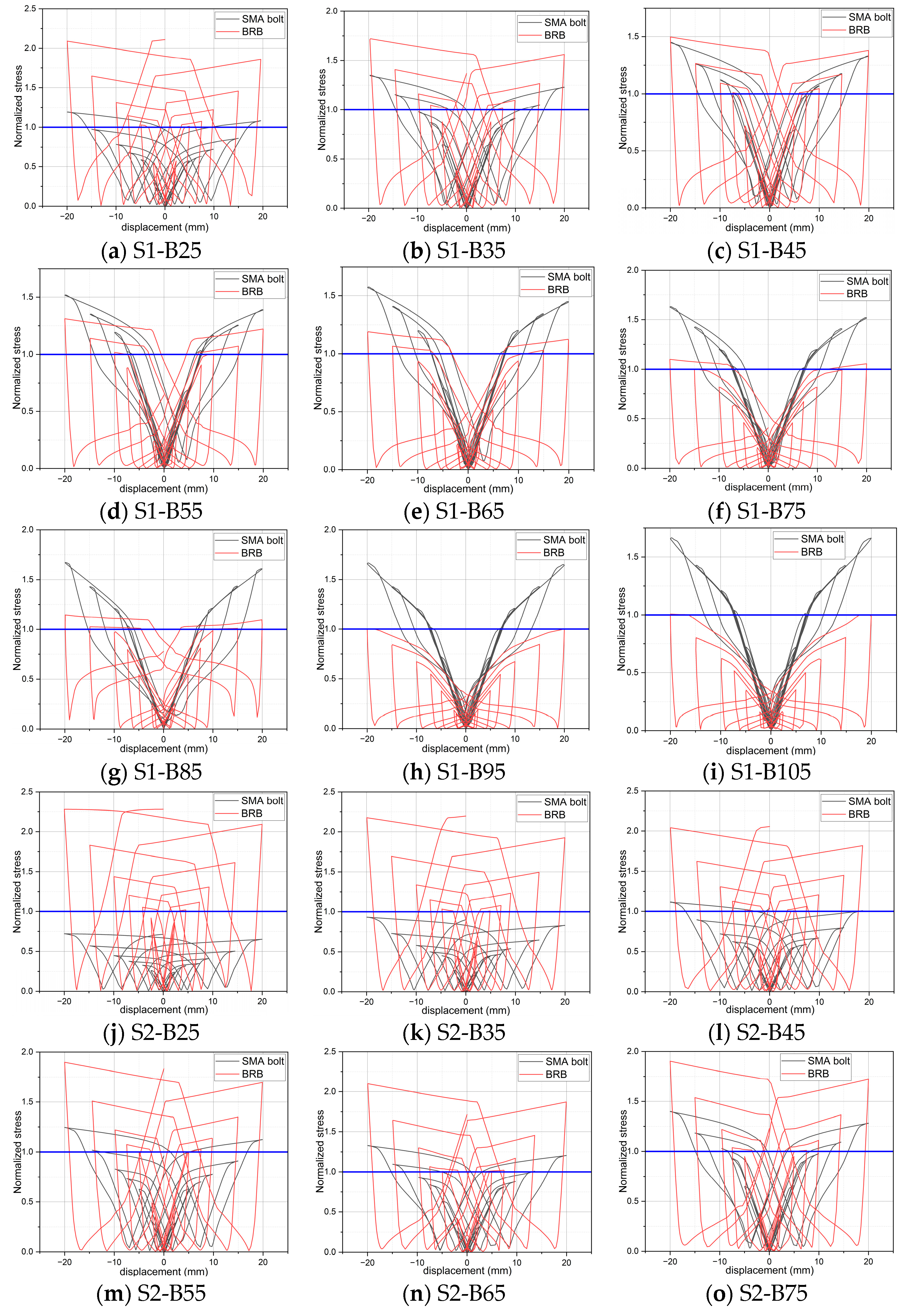
To identify the double-stage yielding points of the DSY-BRB, the stress–displacement responses of the SMA bolts and BRB core plates were obtained through FEM simulation. Considering that the yield stresses of SMA bolts and BRB core plates are not identical, this study introduces a normalized stress parameter, defined as the ratio of the component’s instantaneous stress to its corresponding yield stress. A normalized stress value of 1 precisely marks the onset of yielding; values greater than 1 indicate that yielding has already occurred, and values less than 1 reflect that the component remains in the elastic phase. Thus, normalized stress acts as a unified and standardized criterion for assessing the yielding state of both SMA bolts and BRB core plates. This allows the yield displacements and the sequence of yielding for both elements to be determined in a consistent, direct manner. FEM simulations were performed for all DSY-BRB specimens listed in Table 7, with the resulting normalized stress–displacement curves illustrated in Figure 16. The key mechanical properties for each specimen—including the yield force, yield displacement, ultimate load capacity, and yielding sequence of both the SMA sliding friction dampers and BRBs for the first and second yield stages—are summarized in Table 7. As presented in Figure 16, for specimens S2-B25 and S2-B35, the normalized stress of the SMA bolts remained below 1 throughout the entire loading process, indicating that the SMA sliding friction dampers did not transition into the yielding and energy dissipation stage. In contrast, for the remaining specimens, either the SMA bolts or the BRB center plates achieved a normalized stress value of 1 during the simulation, confirming that these configurations are capable of realizing double-stage yielding as intended.
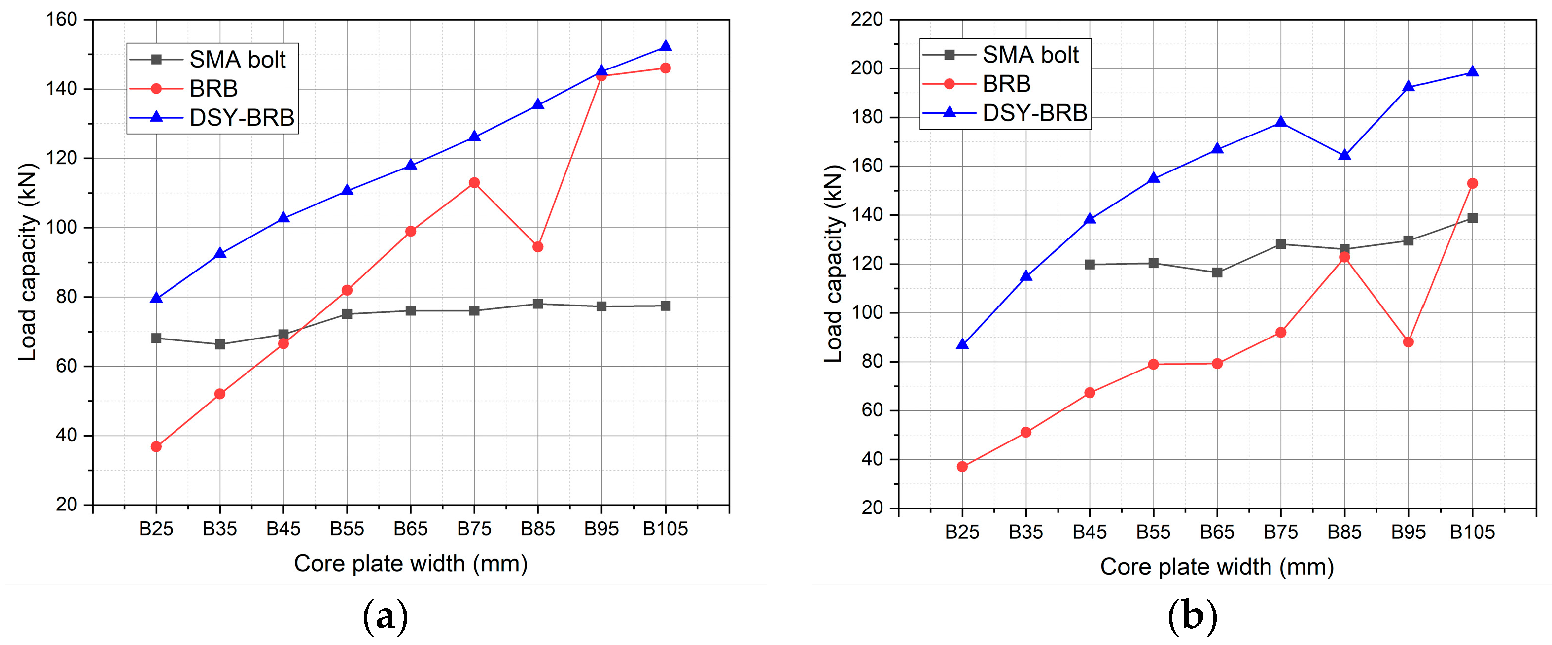
Figure 17 presents the relationship of the yield load-carrying capacities of the SMA bolts and BRBs, as well as the ultimate load-carrying capacity of DSY-BRBs with the core plate width, corresponding to the use of two SMA bolts (n = 1) and four SMA bolts (n = 2), respectively. As illustrated in the figure, the ultimate load-carrying capacity of DSY-BRBs generally increases with both the number of SMA bolts and the width of the BRB core plate. When the number of SMA bolts is held constant, increasing the core plate width of the BRB results in a higher yield load for the BRB, and the load required to yield the SMA bolts also rises when the core plate width is below 55 mm. However, when the core plate width exceeds 65 mm, the yield load of the SMA bolts tends to stabilize. Conversely, when the width of the BRB core plate is kept constant, increasing the number of SMA bolts leads to an increase in the yield load of the SMA bolts, while the yield load of the BRB remains largely unaffected. These results indicate that the stiffness ratio between the SMA bolts and the BRB core plate plays a crucial role in determining the sequence of yielding for the two components. It is worth noting that some anomalies are observed in the figure, for example: an unexpected reduction in the yield load-carrying capacity of the BRB in the S1-B85 specimen. This abnormality may arise from FEM mesh density effects, which could introduce constraint deviations in the BRB core plate and result in its premature yielding.
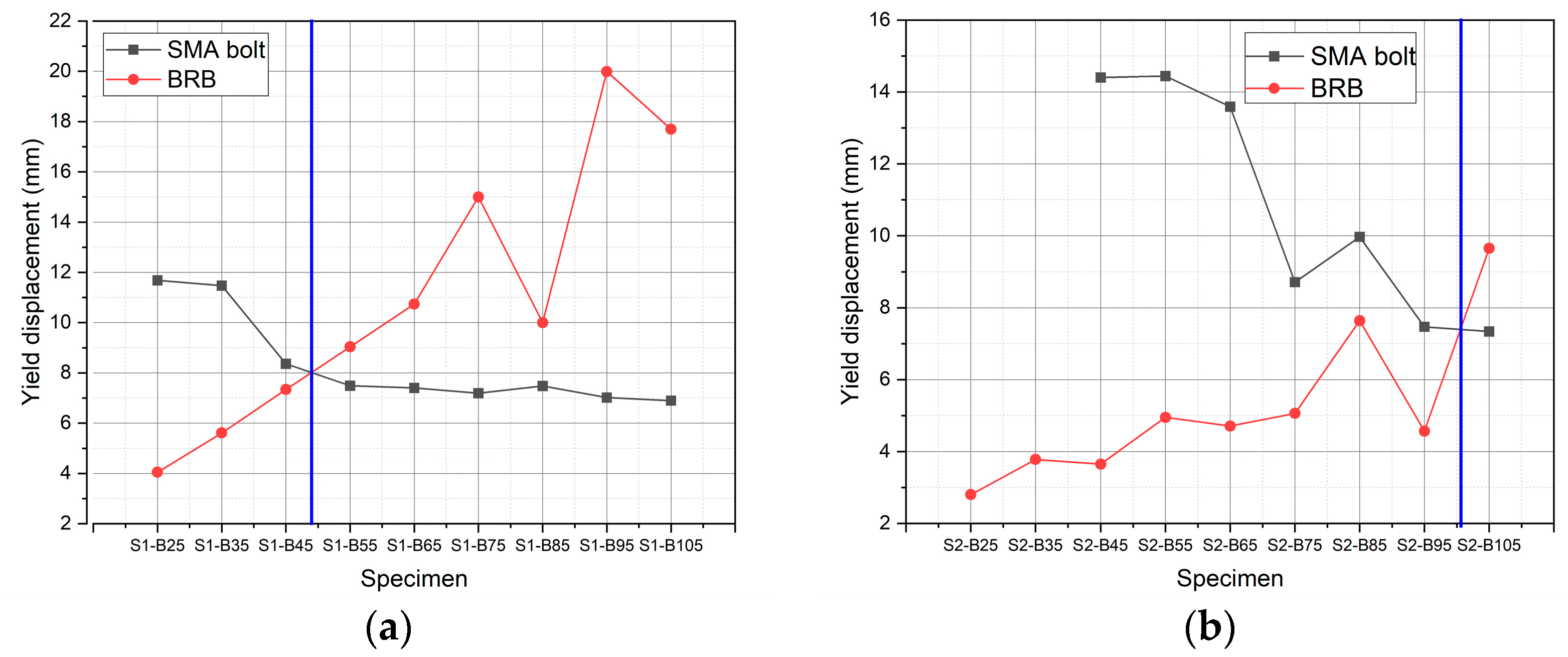
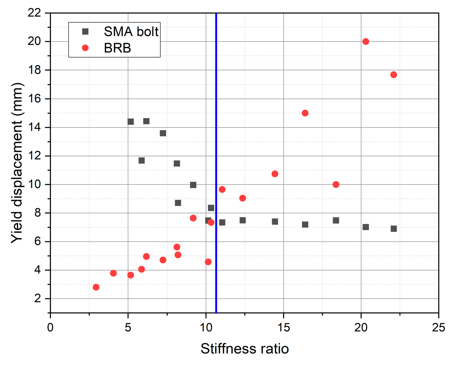
Figure 18 illustrates the relationship between the yield displacement of SMA bolts and BRB with the width of the BRB core plate, under conditions where the SMA sliding friction damper is equipped with either two (n = 1) or four (n = 2) bolts. Building on this, Figure 19 presents the yield displacement of both SMA bolts and BRB core plates as a function of the stiffness ratio between the BRB and the SMA sliding friction damper.
As shown in Figure 19, the blue boundary line divides the parameter space into two distinct regions: To the left of the blue line, the SMA bolts exhibit a greater yield displacement than the BRB core plates, signifying that the BRB yields first. To the right of the blue line, the converse is true—the BRB core plate’s yield displacement exceeds that of the SMA bolts, indicating that the SMA sliding friction damper yields first. This behavior arises because, during the loading of DSY-BRB specimens, the component with the smaller yield displacement initiates yielding earlier. Thus, Figure 19 demonstrates that the stiffness ratio directly influences the yield sequence of the BRB and the SMA sliding friction damper. Specifically, when the stiffness ratio is below the threshold corresponding to the blue line (10.33–11.05), the BRB yields before the SMA sliding friction damper. Conversely, when the stiffness ratio exceeds this threshold, the SMA sliding friction damper yields before the BRB. Therefore, theoretically, a stiffness ratio within the range of 10.33–11.05 results in the simultaneous yielding of both components.
A detailed examination of the region left of the blue line—where the BRB yields first—reveals that as the stiffness ratio increases, the first-stage yield displacement of the specimen rises steadily, while the second-stage yield displacement diminishes until both converge, at which point simultaneous yielding occurs. In the region where the SMA sliding friction damper yields first (to the right of the blue line), the first-stage yield displacement remains nearly constant (typically within 7–7.5 mm), except for specimen S2-B105, whose stiffness ratio approximates the blue boundary. Furthermore, for all specimens in this region (excluding S2-B105), the number of SMA bolts is two (n = 1), suggesting that the first-stage yield displacement in these configurations is governed exclusively by the SMA sliding friction damper. The gradual increase in the second-stage yield displacement is attributed to the progressive decrease in the overall specimen stiffness, transitioning toward the post-yield stiffness of the SMA sliding friction damper. Thus, the second-stage yield displacement is mainly determined by the second-stage yield force of the SMA sliding friction damper, which increases as the core plate width grows.
According to the design guidelines for DSY-BRBs, the SMA sliding friction damper should yield before the BRB. Therefore, it is recommended that the stiffness ratio between the BRB and the SMA sliding friction damper be maintained above 11.05 in DSY-BRB assemblies, while other design parameters should be selected based on the required load-bearing capacity of the structure.

4.4. Discussion

As shown in Figure 15, the hysteresis curve of the DSY-BRB test specimen exhibits a flag-shaped pattern, primarily traversing through quadrants 1 and 3, whereas the hysteresis curve of the finite element simulation model spans all four quadrants, resulting in the aforementioned differences. Analyzing the components that make up the DSY-BRB, the hysteresis curve of the SMA sliding friction damper exhibits a flag-shaped pattern, passing through quadrants 1 and 3, while the traditional BRB exhibits a typical steel hysteresis curve, which spans all four quadrants. By connecting the SMA sliding friction damper and BRB in series, the superimposed hysteresis curve should resemble that of the FEM model, spanning all four quadrants while exhibiting self-centering characteristics toward the origin in quadrants 2 and 4. Regarding the aforementioned issues, a stress analysis of the FEM model for the DSY-BRB revealed that both the SMA bolts and BRB core plates had entered the yield stage. For the test specimen, after disassembling the core plate post-test, it was found to have undergone bending deformation. However, due to the constraint effect of the concrete, the core plate did not fully enter the yield stage. Additionally, since the SMA bolt threads failed prematurely, the BRB’s yield energy dissipation was not fully utilized, resulting in a flag-shaped hysteresis curve similar to that of the SMA sliding friction damper. We consider that if the SMA bolts could continue to function during the subsequent loading process of the DSY-BRB specimen, the BRB could also fully yield and dissipate energy, causing its hysteresis curve to similarly traverse all four quadrants, thereby aligning with the results of the FEM model and enhancing energy dissipation capacity.

5. Conclusions

This study introduces a DSY-BRB that integrates SMA sliding friction dampers and BRBs, leveraging the activation characteristics of SMA materials. Through quasi-static experiments and FEM parametric analyses, the structural rationality and working mechanism of the DSY-BRB were systematically validated. The principal conclusions are as follows:
(1)
The SMA sliding friction damper, designed based on phase-change SMA subjected to high-temperature pre-treatment, demonstrates negligible residual deformation. The incorporation of sliding friction not only enhances the damper’s energy dissipation ability under large deformations but also endows it with reliable self-centering performance.
(2)
Quasi-static testing of DSY-BRB specimens revealed that failure predominantly occurred at the threaded end of the SMA bolt. The specimens exhibited stable, full, flag-shaped hysteresis loops with excellent tension–compression symmetry and clear double-stage yielding characteristics, indicating outstanding energy dissipation and self-centering capacities.
(3)
FEM simulations, with varied core plate widths and SMA bolt numbers, showed that the stiffness ratio of the DSY-BRB is a critical parameter influencing the yield order of the BRB and the SMA sliding damper. Specifically, a higher stiffness ratio causes the SMA damper to yield before the BRB, while a stiffness ratio between 10.33 and 11.05 results in simultaneous yielding.
Therefore, it is recommended that the DSY-BRB be designed with a stiffness ratio greater than 11.05 for optimal performance, with other parameters determined according to the structural load requirements. It should be noted that, due to the limited scope of experimental tests and FEM parametric analyses conducted in this study, the conclusions drawn herein would benefit from further validation through additional extensive experimental investigations.
Future research should address several important aspects to advance DSY-BRB technology. Expanded experimental validation with additional specimens and conventional BRB controls is needed to strengthen the reliability of the proposed stiffness ratio guidelines and better quantify performance advantages. The durability and long-term behavior of DSY-BRB systems under manufacturing tolerances, preload degradation, and bolt loosening require investigation to ensure reliable field performance. Additionally, practical implementation studies should evaluate economic feasibility and develop standardized construction procedures for real-world applications. Understanding the behavior of DSY-BRB under complex loading conditions, including multi-directional seismic excitation and combined loads, will also be essential for comprehensive design guidance.

Author Contributions

H.H.: Investigation, data curation, writing—original draft preparation. J.W.: Funding acquisition, investigation, writing—reviewing, and supervision. P.Z.: Funding acquisition, validation, and supervision. D.Y.: Investigation. S.Z.: Resources, validation. All authors have read and agreed to the published version of the manuscript.

Funding

This research was funded by the Basic Public Welfare Research Project of Zhejiang Province, China (LGG22E080004), and the Construction Research Project of Zhejiang Province, China (2021K128, 2024K362).

Data Availability Statement

The raw/processed data required to reproduce these findings cannot be shared at this time, as the data also forms part of an ongoing study. The datasets generated during and/or analyzed during the current study are available from the corresponding author upon reasonable request.

Acknowledgments

The authors would like to express their gratitude for the invaluable assistance provided by Xiaohua JI during the execution of the experiments. The authors would also like to acknowledge the support received from the Center for Balance Architecture and the Architectural Design & Research Institute Co., Ltd. of Zhejiang University in the research project.

Conflicts of Interest

Author Jiyang Wang was employed by the company The Architectural Design & Research Institute of Zhejiang University Co., Ltd. Author Dong Yao was employed by the company Zhejiang Building—Tech Energy Dissipation Technology Co., Ltd. The remaining authors declare that the research was conducted in the absence of any commercial or financial relationships that could be construed as a potential conflict of interest.

References

  1. Sok, A.; Yamada, S.; Iyama, J. Displacement Control of Existing Steel Moment-Resisting Frame Structures Using Buckling-Restrained Braces. J. Earthq. Eng. 2024, 28, 1–21. [Google Scholar] [CrossRef]
  2. Xu, L.Y.; Nie, X.; Fan, J.S. Cyclic behaviour of low-yield-point steel shear panel dampers. Eng. Struct. 2016, 126, 391–404. [Google Scholar] [CrossRef]
  3. Mualla, I.H.; Belev, B. Performance of steel frames with a new friction damper device under earthquake excitation. Eng. Struct. 2002, 24, 365–371. [Google Scholar] [CrossRef]
  4. Zhang, R.H.; Soong, T. Seismic design of viscoelastic dampers for structural applications. J. Struct. Eng. 1992, 118, 1375–1392. [Google Scholar] [CrossRef]
  5. Martinez-Rodrigo, M.; Romero, M.L. An optimum retrofit strategy for moment resisting frames with nonlinear viscous dampers for seismic applications. Eng. Struct. 2003, 25, 913–925. [Google Scholar] [CrossRef]
  6. Sabelli, R.; Mahin, S.; Chang, C. Seismic demands on steel braced frame buildings with buckling-restrained braces. Eng. Struct. 2003, 25, 655–666. [Google Scholar] [CrossRef]
  7. Özkılıç, Y.O.; Bozkurt, M.B. Experimentally investigation of replaceable reduced beam section utilizing beam splice connection. Steel Compos. Struct. 2024, 52, 109. [Google Scholar]
  8. Özkılıç, Y.O.; Bozkurt, M.B. Numerical validation on novel replaceable reduced beam section connections for moment-resisting frames. Structures 2023, 50, 63–79. [Google Scholar] [CrossRef]
  9. Özkılıç, Y.O.; Ün, E.M.; Topkaya, C. Frictional mid-spliced shear links for eccentrically braced frames. Earthq. Eng. Struct. Dyn. 2023, 52, 5050–5071. [Google Scholar] [CrossRef]
  10. Afsar Dizaj, E.; Fanaie, N.; Zarifpour, A. Probabilistic seismic demand assessment of steel frames braced with reduced yielding segment buckling restrained braces. Adv. Struct. Eng. 2018, 21, 1002–1020. [Google Scholar] [CrossRef]
  11. Mirtaheri, S.M.; Nazeryan, M.; Bahrani, M.K.; Nooralizadeh, A.; Montazerian, L.; Naserifard, M. Local and global buckling condition of all-steel buckling restrained braces. Steel Compos. Struct. 2017, 23, 217–228. [Google Scholar] [CrossRef]
  12. Hoveidae, N. Numerical investigation of seismic response of hybrid buckling restrained braced frames. Period. Polytech Civ. Eng. 2019, 63, 130–140. [Google Scholar] [CrossRef]
  13. Ebadi Jamkhaneh, M.; Homaioon Ebrahimi, A.; Shokri Amiri, M. Seismic performance of steel-braced frames with an all-steel buckling restrained brace. Pract. Period. Struct. Des. Constr. 2018, 23, 04018016. [Google Scholar] [CrossRef]
  14. Kim, D.H.; Yoo, J.H. Analytical Study on a Prototype of Buckling Restrained Braces Reinforced with Steel Plate. Int. J. Steel Struct. 2022, 22, 1841–1849. [Google Scholar] [CrossRef]
  15. Takeuchi, T.; Hajjar, J.F.; Matsui, R.; Nishimoto, K.; Aiken, I.D. Effect of local buckling core plate restraint in buckling restrained braces. Eng. Struct. 2012, 44, 304–311. [Google Scholar] [CrossRef]
  16. Yazdi, H.M.; Mosalman, M.; Soltani, A.M. Seismic study of buckling restrained brace system without concrete infill. Int. J. Steel Struct. 2018, 18, 153–162. [Google Scholar] [CrossRef]
  17. Pandikkadavath, M.S.; Sahoo, D.R. Development and subassemblage cyclic testing of hybrid buckling-restrained steel braces. Earthq. Eng. Eng. Vib. 2020, 19, 967–983. [Google Scholar] [CrossRef]
  18. Oh, S.; Kurama, Y.C.; Mohle, J.; Polster, L.; Manning, M.; Weldon, B.D. A novel reinforced-concrete buckling-restrained brace for precast concrete lateral-load-resisting frames. PCI J. 2023, 68, 95–116. [Google Scholar] [CrossRef]
  19. Pan, P.; Li, W.; Nie, X.; Deng, K.; Sun, J. Seismic performance of a reinforced concrete frame equipped with a double-stage yield buckling restrained brace. Struct. Des. Tall Spec. Build. 2017, 26, e1335. [Google Scholar] [CrossRef]
  20. Li, G.; Sun, Y.; Jiang, J.; Sun, F.; Ji, C. Experimental study on two-level yielding buckling-restrained braces. J. Constr. Steel Res. 2019, 159, 260–269. [Google Scholar] [CrossRef]
  21. Hu, B.; Min, Y.; Wang, C.; Xu, Q.; Keleta, Y. Design, analysis and application of the double-stage yield buckling restrained brace. J. Build. Eng. 2022, 48, 103980. [Google Scholar] [CrossRef]
  22. Yang, C.; Xie, L.; An, N.; Li, A.; Liu, Q.; Wang, X. Development of a novel parallel double-stage yielding buckling restrained brace: Theoretical, experimental, and numerical investigations. J. Build. Eng. 2023, 68, 106089. [Google Scholar] [CrossRef]
  23. Wu, C.; Zhang, Q.; Gong, C.; Li, D.; Zhang, Y.; Chen, Z. A double-stage buckling restrained brace with progressive failure pattern: Experimental verification and numerical calibration. Structures 2024, 62, 106242. [Google Scholar] [CrossRef]
  24. Zhai, Z.; Liu, Y.; Mercan, O.; Zou, S.; Zhou, F. A hybrid buckling-restrained brace for enhancing the seismic performance of steel moment resisting frames. Soil Dyn. Earthq. Eng. 2024, 178, 108464. [Google Scholar] [CrossRef]
  25. Yang, C.; Xie, L.; Liu, Q.; Li, A.; Liu, Q.; Wang, X. Dual-objective control of braced steel frame using asynchronized parallel two-stage yielding BRB. Soil Dyn. Earthq. Eng. 2024, 179, 108522. [Google Scholar] [CrossRef]
  26. Xiong, C.; Cao, Y.; Wang, T.; Xie, L.; Wu, D. Experimental and numerical studies of a core plate repairable double-stage yield buckling-restrained brace. J. Constr. Steel Res. 2024, 223, 109006. [Google Scholar] [CrossRef]
  27. Kawashima, K.; MacRae, G.A.; Hoshikuma, J.; Nagaya, K. Residual displacement response spectrum. J. Struct. Eng. 1998, 124, 523–530. [Google Scholar] [CrossRef]
  28. McCormick, J.; Aburano, H.; Ikenaga, M.; Nakashima, M. Permissible residual deformation levels for building structures considering both safety and human elements. In Proceedings of the 14th World Conference on Earthquake Engineering, Beijing, China, 12–17 October 2008; Seismological Press: Beijing, China, 2008. [Google Scholar]
  29. Özkılıç, Y.O.; Bozkurt, M.B.; Topkaya, C. Mid-spliced end-plated replaceable links for eccentrically braced frames. Eng. Struct. 2021, 237, 112225. [Google Scholar] [CrossRef]
  30. Hui, D.; Yu, B.; Qiang, H.; Xiu, D. Mechanical performance of new type of self-centering energy dissipation brace and its application in double-column bridge structures. China J. Highw. Transp. 2017, 30, 196–204. (In Chinese) [Google Scholar]
  31. Qing, Y.; Wang, C.L.; Zhou, Z.; Zeng, B. Seismic responses of multistory buildings with self-centering buckling-restrained braces: Influence of the pretension force. Eng. Struct. 2021, 238, 112249. [Google Scholar] [CrossRef]
  32. Zhang, C.; Guo, X.; Luo, J.; Chen, S. Seismic design and performance evaluation of steel braced frames with post-tensioned and disc-spring-based self-centering buckling-restrained braces. Soil Dyn. Earthq. Eng. 2024, 180, 108602. [Google Scholar] [CrossRef]
  33. Han, Y.L.; Xing, D.J.; Xiao, E.T.; Li, A.Q. NiTi-wire shape memory alloy dampers to simultaneously damp tension, compression, and torsion. J. Vib. Control 2005, 11, 1067–1084. [Google Scholar] [CrossRef]
  34. Zhao, X.; Liu, Z.; Wang, S.; Yang, T.; Zhan, M. Design and analysis of an innovative hybrid shape memory alloys viscous damper. J. Earthq. Eng. Eng. Vib. 2016, 36, 72–78. [Google Scholar]
  35. Alipour, A.; Kadkhodaei, M.; Safaei, M. Design, analysis, and manufacture of a tension–compression self-centering damper based on energy dissipation of pre-stretched superelastic shape memory alloy wires. J. Intell. Mater. Syst. Struct. 2017, 28, 2129–2139. [Google Scholar] [CrossRef]
  36. Liu, M.; Li, H.; Fu, X. Experimental and numerical analysis of an innovative re-centering shape memory alloys-shearing lead damper. Eng. Mech. 2018, 35, 52–57, 67. [Google Scholar]
  37. NourEldin, M.; Naeem, A.; Kim, J. Life-cycle cost evaluation of steel structures retrofitted with steel slit damper and shape memory alloy–based hybrid damper. Adv. Struct. Eng. 2019, 22, 3–16. [Google Scholar] [CrossRef]
  38. Tian, L.; Gao, G.; Qiu, C.; Rong, K. Effect of hysteresis properties of shape memory alloy-tuned mass damper on seismic control of power transmission tower. Adv. Struct. Eng. 2019, 22, 1007–1017. [Google Scholar] [CrossRef]
  39. Yang, W.; Cao, S.; Liu, W.; Dang, X. Mechanical properties of a novel friction dampers incorporated with buckling restrained shape memory alloy bars. Adv. Bridge Eng. 2024, 5, 21. [Google Scholar] [CrossRef]
  40. Gur, S.; Xie, Y.; DesRoches, R. Seismic fragility analyses of steel building frames installed with superelastic shape memory alloy dampers: Comparison with yielding dampers. J. Intell. Mater. Syst. Struct. 2019, 30, 2670–2687. [Google Scholar] [CrossRef]
  41. Qiu, C.; Liu, J.; Du, X. Cyclic behavior of SMA slip friction damper. Eng. Struct. 2022, 250, 113407. [Google Scholar] [CrossRef]
  42. Qiu, C.; Liu, J.; Jiang, T.; Du, X. Tests of double-stage SMA slip friction damper. Eng. Struct. 2023, 288, 116171. [Google Scholar] [CrossRef]
  43. Wang, W.; Fang, C.; Liu, J. Large size superelastic SMA bars: Heat treatment strategy, mechanical property and seismic application. Smart Mater. Struct. 2016, 25, 075001. [Google Scholar] [CrossRef]
  44. Qiu, C.; Yang, Y.; Liu, J.; Jiang, T. Test of a novel self-centering brace using SMA slip friction damper. J. Constr. Steel Res. 2023, 204, 107872. [Google Scholar] [CrossRef]
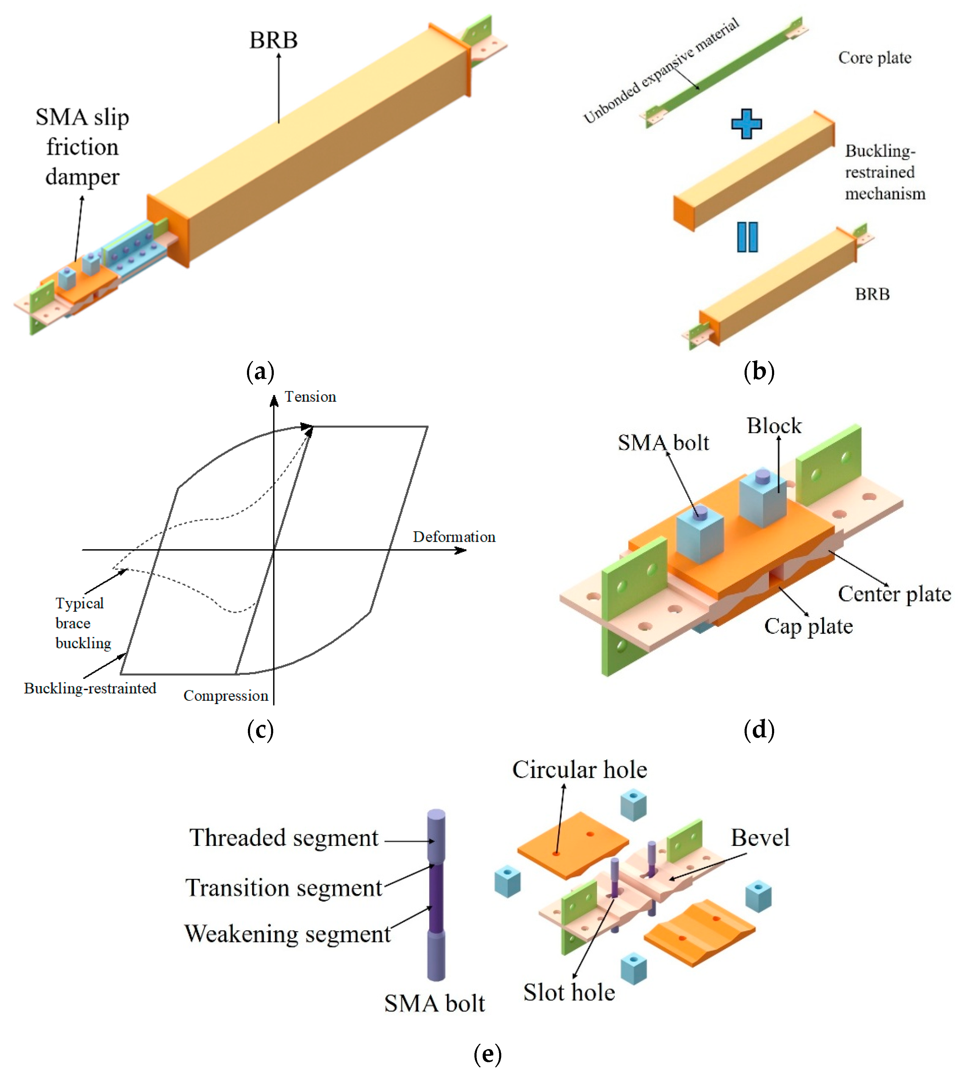
Figure 1. Configuration of DSY-BRB: (a) Overall layout: a conventional BRB connected in series with an SMA sliding friction damper; (b) BRB assembly: an axial load-bearing core, a lateral-restraining casing to prevent buckling, and an unbonded layer to reduce interface friction; (c) performance comparison between a BRB and a conventional (unrestrained) brace; (d) basic configuration of the SMA sliding friction damper; (e) components of the SMA sliding friction damper: SMA bolts with reduced sections to localize deformation; a center plate and cap plate that dissipate energy via relative sliding friction along an inclined interface.
Buildings 15 03225 g001
Figure 2. Working mechanism: (a) SMA slip friction damper: Under tension or compression, the center plate slides relative to the cap plate, stretching the SMA bolts. The resulting bolt elongation increases normal force at the inclined interface, generating friction and dissipating energy; (b) ideal force-displacement response of the DSY-BRB.
Buildings 15 03225 g002
Figure 3. Test of SMA: (a) Dimension (mm); (b) before and after heat treatment; (c) test setup; (d) loading protocol; (e) hysteresis curve.
Buildings 15 03225 g003
Figure 4. Specimen of SMA slip friction damper: (a) Assembled specimen; (b) all parts of the specimen.
Buildings 15 03225 g004
Figure 5. Test of SMA slip friction damper: (a) Test setup; (b) loading protocol; (c) hysteresis curve.
Buildings 15 03225 g005
Figure 6. Components of the DSY-BRB specimen: (a) BRB; (b) SMA slip friction damper (n = 2); (c) SMA slip friction damper (n = 4); (d) flange plate. (Dimension: mm).
Buildings 15 03225 g006
Figure 7. Test setup: (a) Photograph; (b) schematic.
Buildings 15 03225 g007
Figure 8. Experimental observations: (a) SMA bolt breakage; (b) core plate of S1-B25.
Buildings 15 03225 g008
Figure 9. Hysteresis curves: (a) S1-B25; (b) S1-B55; (c) S1-B85.
Buildings 15 03225 g009
Figure 10. Hysteresis parameters: (a) Peak strength (Fmax); (b) secant stiffness (ksec); (c) dissipated energy (WD); (d) equivalent viscous damping ratio (ξeq).
Buildings 15 03225 g010
Figure 11. Constitutive model: (a) SMA; (b) steel.
Buildings 15 03225 g011
Figure 12. FEM model after meshing of DSY-BRB.
Buildings 15 03225 g012
Figure 13. Loading protocol.
Buildings 15 03225 g013
Figure 14. Stress cloud map for S1-B55: (a) 7.19 mm; (b) 9.95 mm.
Buildings 15 03225 g014
Figure 15. Comparisons between experimental and FEM results: (a) S1-B25; (b) S1-B55; (c) S1-B85.
Buildings 15 03225 g015
Figure 16. Normalized stress–displacement curves. Note: The blue line indicates the normalized stress value of 1, which marks the onset of yielding.
Buildings 15 03225 g016aBuildings 15 03225 g016b
Figure 17. Relationship of the yield load capacity of SMA bolts and BRBs, the ultimate load capacity of DSY-BRBs with the core plate width, (a) n = 1; (b) n = 2.
Buildings 15 03225 g017
Figure 18. Yield displacement of SMA bolts, BRB with the width of the BRB core plate, (a) n = 1; (b) n = 2. Note: The blue line indicates the width of the BRB core plate at which the SMA sliding friction damper and the BRB yield simultaneously.
Buildings 15 03225 g018
Figure 19. Curve of yield displacement with stiffness ratio for SMA bolts and BRB core plate. Note: The blue line indicates the stiffness ratio at which the SMA sliding friction damper and the BRB yield simultaneously.
Buildings 15 03225 g019
Table 1. Hysteretic parameters of SMA.
σMs (MPa)σMf (MPa)σAs (MPa)σAf (MPa)EA (GPa)EM (GPa)
300400250753015
Table 2. Parameters of the DSY-BRB from experimental testing.
Specimen IDBRBSMA Slip Friction Damper
Center Plate Width b (mm)Overall Length
L (mm)
Yield Section
Length l (mm)
Number of SMA Bolts
S1-B2525160011002
S1-B5555
S1-B8585
Table 3. Hysteretic parameters of DSY-BRB and conventional BRB.
Specimen ID.Yield
Displacement (mm)
Fmax
(kN)
ksec
(kN/mm)
WD
(kJ)
ξeq
(%)
Residual
Displacement (mm)
S1-B251.863.1384.0611.200.4210.511.55
S1-B551.944.7879.065.270.749.970.28
S1-B851.835.7086.785.791.3416.390.46
Table 4. Comparison of energy dissipation performance with typical devices from the literature.
Study SourceWD (kJ)ξeq (%)
(This study)1.34 *16.39
Alipour et al. 2017 [35]~0.02311.60
Liu et al. 2018 [36]~0.00514.22
Yang et al. 2024 [39]~0.96~12.00
Qiu et al. 2022 [41]~0.3016.40
Qiu et al. 2023 [42]~0.2315.80
Qiu et al. 2023 [44]~2.00~14.00
Note: * Energy dissipation capacity of half a hysteresis loop, reported owing to premature failure of SMA bolts.
Table 5. Parameters of the DSY-BRB from FEM.
Specimen IDBRBSMA Slip Friction DamperStiffness RatioNormalized Stiffness Ratio
b (mm)Stiffness (kN/mm)nStiffness (kN/mm)
S1-B252542.517.235.882
S1-B353558.817.238.132.75
S1-B454574.717.2310.333.5
S1-B555589.417.2312.374.25
S1-B6565104.517.2314.455
S1-B7575118.517.2316.395.5
S1-B8585132.917.2318.386.25
S1-B9595146.817.2320.307
S1-B105105159.817.2322.107.5
S2-B252542.5214.472.941
S2-B353558.8214.474.061.375
S2-B454574.7214.475.171.75
S2-B555589.4214.476.182.125
S2-B6565104.5214.477.232.5
S2-B7575118.5214.478.202.75
S2-B8585132.9214.479.183.125
S2-B9595146.8214.4710.153.5
S2-B105105159.8214.4711.053.75
Note: b is the width of the core plate; n is the number of SMA bolts per center plate.
Table 6. Simulated and experimental values of peak load and secant stiffness.
Specimen IDPeak LoadSecant Stiffness
Simulated (kN)Experimental (kN)Error (%)Simulated (kN/mm)Experimental (kN/mm)Error (%)
S1-B2539.6984.0652.85.4511.2151.4
S1-B5575.1173.951.610.0110.252.3
S1-B8578.0569.7211.910.439.944.9
Table 7. FEM results for each specimen.
Specimen ID.Stiffness RatioFirst-Stage Yield Force (kN)First-Stage Yield
Displacement (mm)
Second-Stage Yield Force (kN)Second-Stage Yield
Displacement (mm)
Maximum Force (kN)Yield
Sequence
S1-B255.8836.794.0568.1211.6879.47B → S
S1-B358.1352.025.6166.3511.4792.42B → S
S1-B4510.3366.507.3469.208.36102.68B → S
S1-B5512.3775.117.4981.949.04110.60S → B
S1-B6514.4576.067.4098.9610.74117.91S → B
S1-B7516.3976.067.19112.9515.00126.13S → B
S1-B8518.3878.057.4894.4610.00135.33S → B
S1-B9520.3077.307.02143.7319.99145.06S → B
S1-B10522.1077.486.90146.0317.69152.14S → B
S2-B252.9437.042.80--86.77B
S2-B354.0651.123.78--114.75B
S2-B455.1767.293.65119.7914.40138.19B → S
S2-B556.1878.984.95120.414.44154.87B → S
S2-B657.2379.264.71116.4913.59166.92B → S
S2-B758.2092.065.06128.168.71177.86B → S
S2-B859.18122.817.64126.089.97164.28B → S
S2-B9510.1588.074.57129.617.47192.40B → S
S2-B10511.05138.807.34152.989.65198.38S → B
Note: B is BRB; S is SMA slip friction damper; The arrow “→” indicates the sequence of yielding, where the component before the arrow yields prior to the one after it.
Disclaimer/Publisher’s Note: The statements, opinions and data contained in all publications are solely those of the individual author(s) and contributor(s) and not of MDPI and/or the editor(s). MDPI and/or the editor(s) disclaim responsibility for any injury to people or property resulting from any ideas, methods, instructions or products referred to in the content.