Article

Blast-Resistant Performance Evaluation of Steel Box Girder of Suspension Bridge

1
School of Civil and Environmental Engineering, Changsha University of Science & Technology, Changsha 410114, China
2
College of Civil Engineering, Tongji University, Shanghai 200092, China
*
Author to whom correspondence should be addressed.
Buildings 2025, 15(17), 3210; https://doi.org/10.3390/buildings15173210
Submission received: 31 July 2025 / Revised: 18 August 2025 / Accepted: 20 August 2025 / Published: 5 September 2025
(This article belongs to the Section Building Structures)

Abstract

Explosions pose significant risks to large-span steel bridges, which are integral to modern transportation networks and construction projects. This study evaluates the blast resistance of the orthotropic bridge deck of the Taizhou Yangtze River Bridge using numerical simulations validated by explosion tests. Five vehicular bomb scenarios, as specified by the Federal Emergency Management Agency, were analyzed to understand the damage mechanisms under above-deck explosions. Results show that all scenarios cause petal-shaped openings in the top plate, fractures in U-stiffeners, and plastic deformation in diaphragms. Larger TNT masses lead to additional failures, such as outward bending and bottom plate openings. Energy dissipation primarily occurs through plastic deformation and failure of various deck components, with the extent depending on the TNT mass. The vehicle shell significantly reduces damage for smaller charges (454 kg TNT) but has a minor effect for larger charges (>4536 kg TNT). This research enhances the understanding of blast resistance in orthotropic steel decks, a key component in modern bridge construction, and informs practices for designing resilient structures.

1. Introduction

Orthotropic steel bridge decks, characterized by their longitudinal and transverse stiffeners welded to the top plate, have been extensively adopted in long-span steel bridges worldwide, including suspension and cable-stayed bridges [1,2]. With the rapid industrial development, hazardous chemicals are now widely utilized, and their accidental explosions during transportation pose significant threats to the transportation capacity of steel bridge decks. Besides, as high-value targets, long-span steel bridges are also threatened by explosions caused by military strikes or terrorist attacks [3,4]. Due to the orthogonal structural configuration, the complex mechanical behavior of the orthotropic steel bridge decks under blast load is to be examined.
Existing studies primarily focus on simplified steel plates or stiffened plates under blast load due to the large dimensions and structural complexity of prototype bridge decks, in addition to the safety issues. Remennikov et al. [5] conducted near-field explosion tests on mild steel, high-strength steel, and stainless-steel plates, and revealed that residual deformations under identical blast loads follow the order: mild steel > stainless steel > high-strength steel. Further, according to ref. [6], they proposed a predictive model for near-field blast impulse. Henchie et al. [7] examined steel plate responses under repeated uniform blast loads through experiments and numerical simulations, and two failure modes were identified, i.e., global plastic deformation with boundary thinning and shear failure at clamped edges. Yang et al. [8] examined the damage mode of steel plate under contact and non-contact explosions, reporting circular craters and minor dents, respectively. Han et al. [9] conducted near-field explosion tests on clamped rectangular steel plates, and three failure modes were categorized, i.e., plastic deformation, critical cracking, and petal-shaped rupture. Yuen et al. [10,11,12] experimentally and numerically analyzed the damage modes of mild steel plates with varying stiffener configurations (unstiffened, single, double, cross, and double-cross stiffeners) under explosion, and found three failure modes, i.e., plastic deformation (Mode I), tensile tearing (Mode II), and shear failure (Mode III). Further studies by Yuen et al. [13] on V-shaped plates under near-field explosions demonstrated that residual deflection increases with apex angles of the V-shape (60–180°), with Modes I and II dominating the damage modes. Gan et al. [14,15] examined U-stiffened plates under blast load, found an additional damage mode of stiffener beyond Modes I-III and proposed a damage parameter to classify these damage modes. Goe et al. [16] numerically demonstrated that stiffeners significantly enhance blast resistance, while Razak et al. [17] revealed stiffener-related tearing and fracture failures. Gan et al. [18] highlighted the superior blast resistance of U-stiffeners over plate-type stiffeners.
Concerning the failure modes of prototype orthotropic bridge decks under explosions, Liu et al. [19] conducted an explosion test on 1/10-scale steel box girders, and found that increasing deck thickness and reducing U-stiffener and diaphragm spacing enhance blast resistance of the girders. Bai [20] numerically revealed that small charges cause local plastic deformation, while larger charges induce cracking and rupture. Jiang et al. [21] carried out numerical simulations of suitcase- and car-bomb explosions on steel box girders, and found that damage severity correlates with charge mass, evolving from plastic deformation to petal-shaped rupture, with over 70% of blast energy dissipated through plastic deformation of the deck and stiffeners. For the vehicle-borne bomb, Hu et al. [22] numerically studied the overpressure field distribution on bridge decks and found that the steel plate of the vehicle body has a significant blocking effect on the propagation of shock waves. Similarly, Zeng [23] also highlighted that the steel plates of the cargo hold change the pressure field distribution, and the empirical formula for predicting overpressure in the free air domain is no longer applicable.
To conclude, the limitations of the existing studies include (i) insufficient finite element (FE) model validation against the experimental data concerning different damage modes, (ii) narrow range of TNT masses and limited damage modes in the numerical simulation analyses, and (iii) ignorance of vehicle shell influence. To address these issues, the blast-resistant performance of orthotropic steel bridge decks under above-deck explosions was evaluated numerically. A refined FE model of the steel box girder deck of Taizhou Yangtze River Highway Bridge was established and validated against the explosion test on a single-stiffened steel plate carried out by Langdon et al. [11] by comparisons of the predicted and experimental damage modes and central deflection of the steel plate. Then, according to classifications of potential terrorist attacks by Federal Emergency Management Agency (FEMA) [24], five explosion scenarios with varying TNT masses (227 kg, 454 kg, 1814 kg, 4536 kg, and 13,608 kg) were designed and analyzed from perspectives of blast wave propagation, damage modes and dynamic responses of the steel bridge deck. Furthermore, the influence of the vehicle shell on the blast-induced damage evolution was discussed. This work is beneficial to the understanding of blast wave propagation and interaction with structures with complex configurations, and the blast-induced bridge damage mechanism.

2. FE Models and Validation

2.1. Test Introduction

Langdon et al. [11] conducted the explosion test on mild steel plates with various stiffener configurations, including unstiffened, single-, double-, and double-cross stiffeners. At present, the single-stiffened steel plate under explosion was used for FE model validation, as presented in Figure 1a. The stiffener has a height of 7 mm and thickness of 3 mm. Plastic explosive (PE4) was employed in the test, with charge masses ranging from 3.5 to 9 g in different test scenarios. The test setup, shown in Figure 1b, involves positioning a cylindrical PE4 charge (36 mm in diameter) centrally above a rectangular steel plate (126 mm × 126 mm × 1.6 mm). The height of the explosive column can be calculated based on the TNT mass.

2.2. FE Models

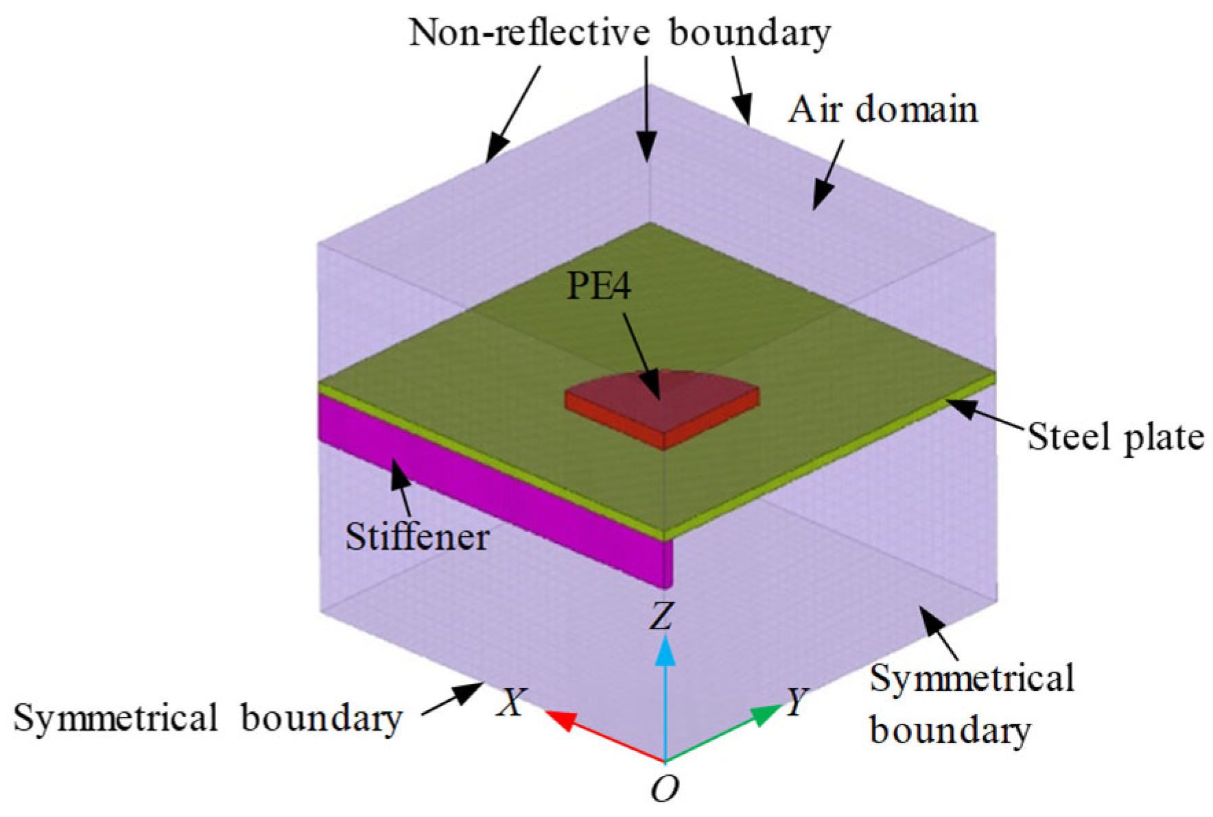
There are mainly three methods to apply blast loads, including the arbitrary Lagrangian–Eulerian (ALE) method, the overpressure-time history method, and the initial velocity method in LS-DYNA [25]. Since the most prerequisite of the overpressure-time history method and initial velocity method is the accurate acquisition of the blast load, and these two methods cannot consider the blast wave propagation and its interaction with the bridge structures, the ALE method was adopted at present, and an 1/4 symmetric FE model of the single-stiffened steel plate under explosion was established, as seen in Figure 2. The model comprises three components, i.e., the air domain, the PE4 explosive, and the steel plate. Symmetric boundary conditions are applied to the XOZ and YOZ planes using the keyword *BOUNDARY_SPC_SET. The steel plate has a fully-fixed boundary using the same keyword *BOUNDARY_SPC_SET, while the air domain has a non-reflective boundary through the keyword *BOUNDARY_NON_REFLECTING. To avoid self-penetration of the steel plates and stiffeners, *CONTACT_AUTOMATIC_SINGLE_SURFACE was adopted. The air and explosive are modeled using ALE elements (*SECTION_SOLID, ELFORM = 11), with mesh sizes of 2 mm and 0.5 mm, respectively. The steel plate/stiffeners are discretized using shell elements (*SECTION_SHELL, ELFORM = 1). All the structure elements share a uniform mesh size of 0.5 mm.

2.2.1. Material Models

As for the air, the null material model and the linear polynomial equation of state (EOS) [25] are adopted, as given in Equation (1). Regarding the TNT, the high-explosive material model and Jones–Wilkins–Lee (JWL) EOS are used to describe the detonation process of the explosive [25], as given in Equation (2). The parameters of the air and TNT material models and EOSs are listed in Table 1. Two material models, i.e., Johnson–Cook material model (*MAT_JOHNSON_COOK/*MAT_15) and plastic kinematic material model (*MAT_PLASTIC_ KINEMATIC/*MAT_3), are adopted and compared to describe the dynamic behavior of the steel plate and stiffeners under extremely high strain rate. The parameters for the Johnson–Cook material model can be referred to ref. [20] and those for the plastic kinematic material model are identical to the actual material properties described in Section 2.1.
P = C 0 + C 1 μ + C 2 μ 2 + C 3 μ 3 + C 4 + C 5 μ + C 6 μ 2 E
μ = 1 V 1
where P , E , and V are the pressure value, initial specific internal energy, and the relative volume, respectively. For linear polynomial EOS of the air, γ = C p / C v , C 0 = C 1 = C 2 = C 3 = C 6 = 0 , C 4 = C 5 = γ 1 , in which γ , C v , C p are the gas adiabatic index, and the heat capacities at constant volume and pressure, respectively.
P = A 1 ω R 1 V e R 1 V + B 1 ω R 2 V e R 2 V + ω E V
where P ,  V , and E are the detonation pressure, the relative volume, and the initial unit volume energy, respectively. The coefficients A , B , R 1 , R 2 , ω are determined experimentally.

2.2.2. Blast Load Application

The application of blast load was implemented using the ALE method, which simulates the interaction between the blast wave and the steel plate through the keyword *CONSTRAINED_LAGRANGE_IN_SOLID. The detonation of the explosive charge at time t = 0 was initiated using the keyword *INITIAL_DETONATION.

2.3. Comparisons

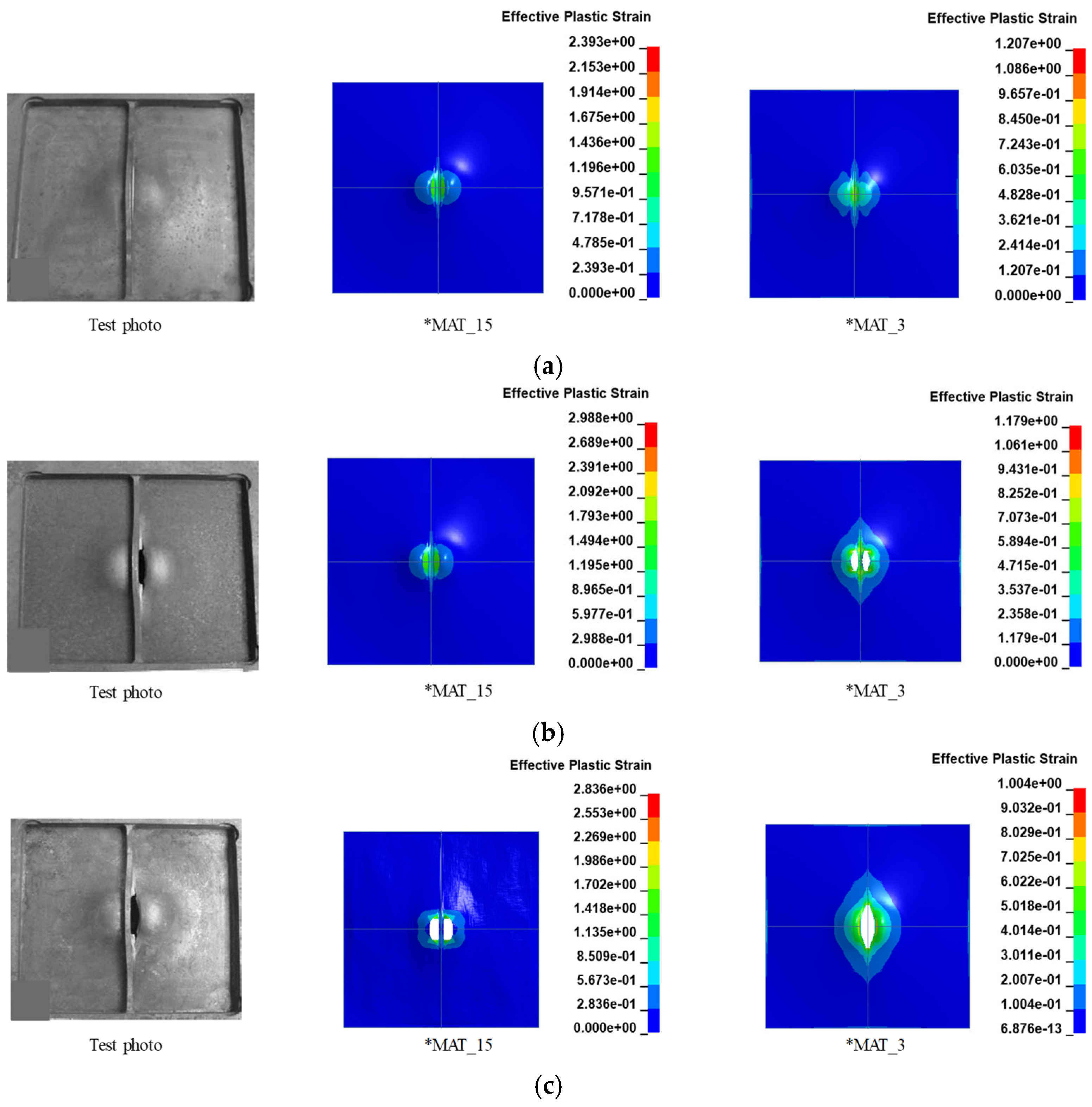
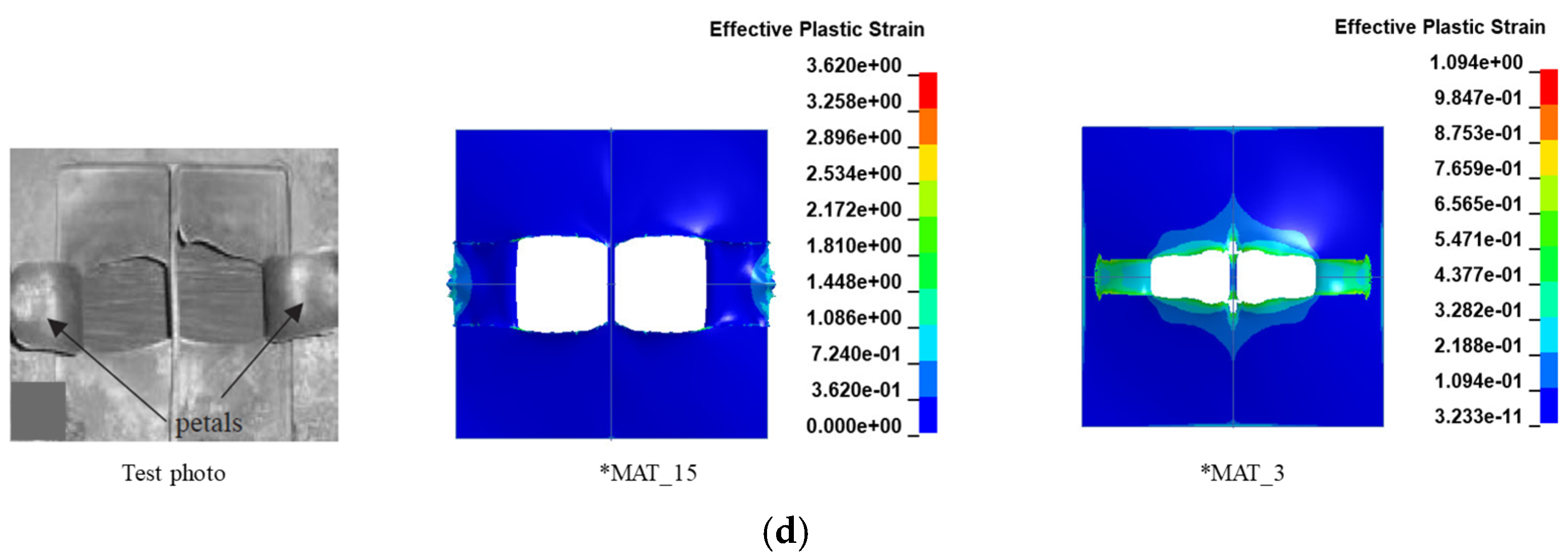
This section presents a comprehensive validation of the adopted numerical simulation method by comparing the predicted results with the experimental data [11] in terms of failure modes and central residual deflections of steel plates. Figure 3 compares the damage patterns between the numerical simulations and experimental observations for single-stiffened steel plates under explosion with PE4 masses of 4 g, 4.5 g, 5 g, and 7 g. Besides, the applicability of two constitutive material models, i.e., *MAT_3 and *MAT_15, for the steel plate and stiffener is discussed. It can be found that, the numerical simulation method with *MAT_3 demonstrates an excellent agreement with experimental results, successfully reproducing key damage modes observed in the tests, i.e., double peak permanent plastic deflection, thinning near the perimeter of these two peaks, tearing along and perpendicular to the stiffener direction, and excessive tearing-induced opening at both sides of the stiffener.
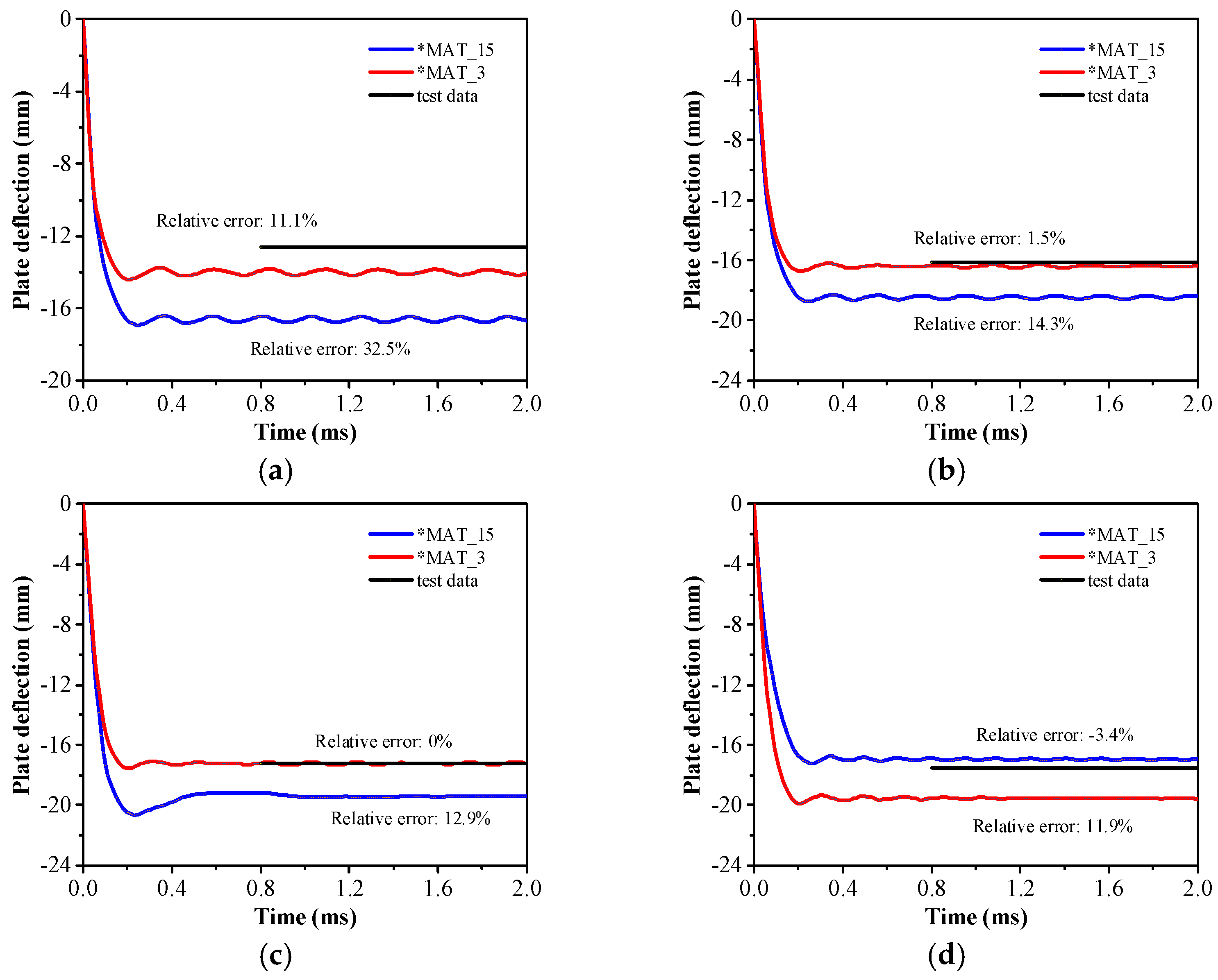
To quantitatively evaluate the effectiveness of the adopted numerical simulation method with these two constitutive models, Figure 4 further compares the central residual deflections of the steel plate between numerical simulations and tests for explosion scenarios with PE4 masses of 4 g, 4.5 g, 5 g, and 7 g, and gives the corresponding relative errors. It can be drawn that the single-stiffened plates in all the scenarios experience large plastic deformation since little resilience can be observed on the deflection-time histories. The discrepancies between the predicted results with material model of *MAT_3 and test data (±12%) are smaller than those with material model of *MAT_15.
The comparative analysis above demonstrates that the adopted numerical simulation method with *MAT_3 can accurately predict both the failure modes and deflection responses of stiffened steel plates under blast loads, and can be used for the dynamic behavior analysis of the prototype orthotropic steel bridge under above-deck explosions.

3. Dynamic Behavior of Orthotropic Steel Bridge Deck Under Above-Deck Explosions

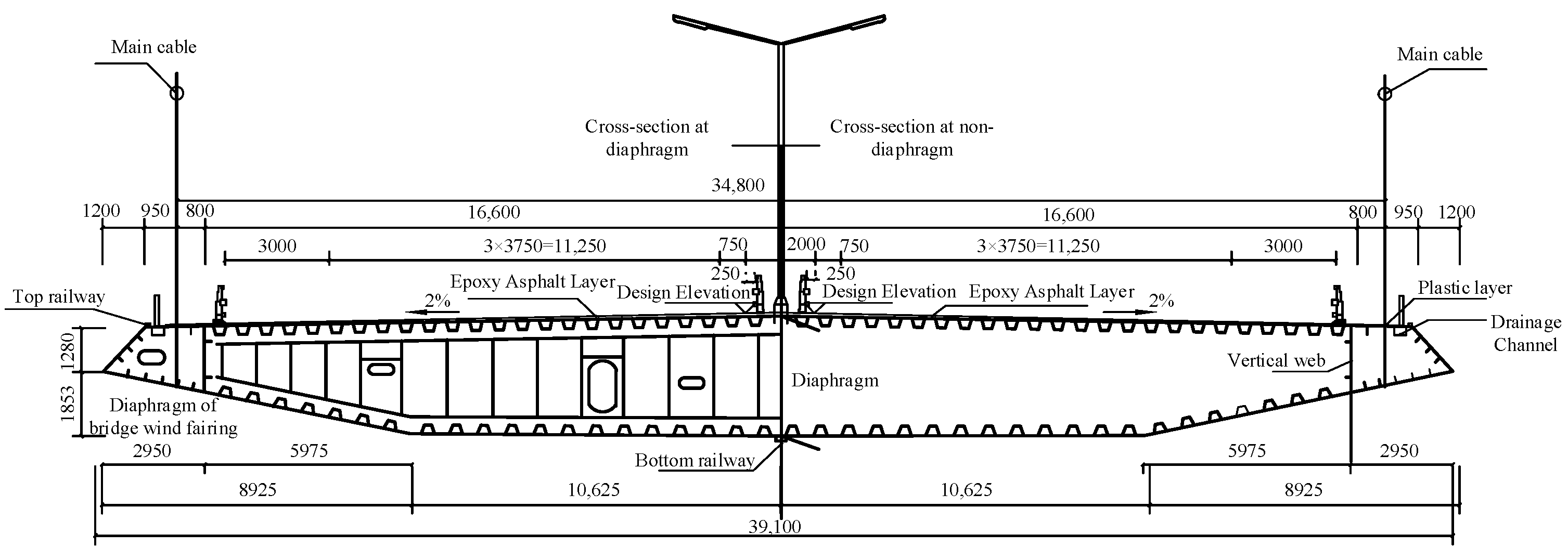
The dynamic behavior of the prototype orthotropic steel bridge, i.e., Taizhou Yangtze River Highway Bridge, under above-deck explosion was rigorously examined. The bridge deck is a single-box three-cell steel box girder structure made of Q345D-grade steel, and is modularized into 136 girder segments, including 128 standard segments with length of 16 m and width of 39.1 m, as illustrated in Figure 5. The thicknesses of steel plates for various components of the box girder are summarized in Table 2.

3.1. FE Model of Prototype Bridge Deck

Figure 6 presents the refined FE model of the steel box girder bridge deck for the Taizhou Yangtze River Highway Bridge. Given that blast loads typically induce localized structural damage, the analysis employs an assembly model composed of 9 girder segments, determined through trial calculations. The element types, contact algorithms, material models, and blast load application methods in the assembly model align with the validated FE model described in Section 2.3. Specifically, the steel bridge adopts shell elements and *MAT_3 with yield strength of 374 MPa, modulus of 210 GPa, and density of 7850 kg/m3. In terms of the mesh sizes, out of capacity of the personal computer consideration, the minimum mesh sizes of the bridge that can guarantee normal computing were determined as 100 mm. Besides, the recommended ratio range of the air mesh size to the bridge mesh size is 1 to 2 [25], and thus the mesh sizes of the air and TNT are 100 mm. The total numbers of the solid and shell elements are 2,818,053 and 1,908,816, respectively. In practical engineering, the connections between components, e.g., top/bottom plates, U-stiffeners, diaphragms, and girder segments, are welded, with the requirement that the mechanical properties of welded joints meet or exceed those of the base material. Accordingly, shared-node connections are adopted between segments in the numerical model. Fixed-end constraints are applied to the nodes at both ends of the assembly model and at the cable suspension points of the steel box girder using the *BOUNDARY_SPC_SET keyword.

3.2. Explosion Scenarios

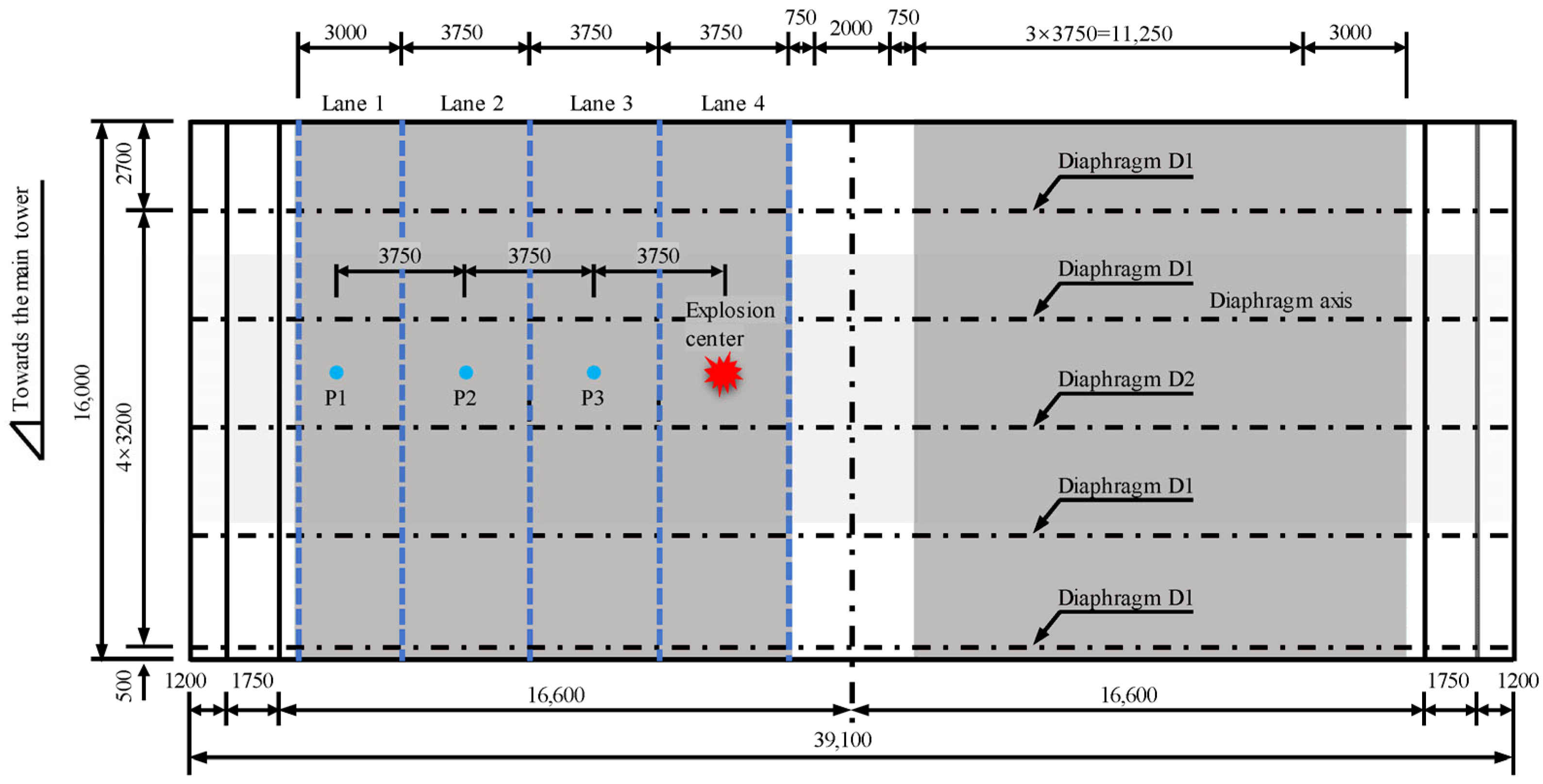
In accordance with terrorist attack-induced explosion scenarios defined by FEMA [24], five vehicle-borne bomb sources (Scenarios A–E) were selected, as detailed in Table 3. Cuboidal charge models were constructed based on their equivalent TNT mass, with the bottom edges of the charges positioned 0.5 m from the bridge deck surface. Regarding the detonation position, Taizhou Yangtze River Highway Bridge features a six-lane bidirectional configuration, with the outermost lanes designated as emergency lanes (Figure 7). Lou [27] pointed out that the explosion at the center of the bridge deck maximizes the global structural response. Consequently, the detonation position was set at the center of Lane 4. To quantitatively evaluate the dynamic behavior of the bridge deck under explosion, three displacement gauges denoted as P1, P2, and P3 were set at a spacing of 3750 mm, and the distance between the detonation point and P3 is also 3750 mm, see Figure 7.

3.3. Results and Discussions

3.3.1. Blast Wave Propagation

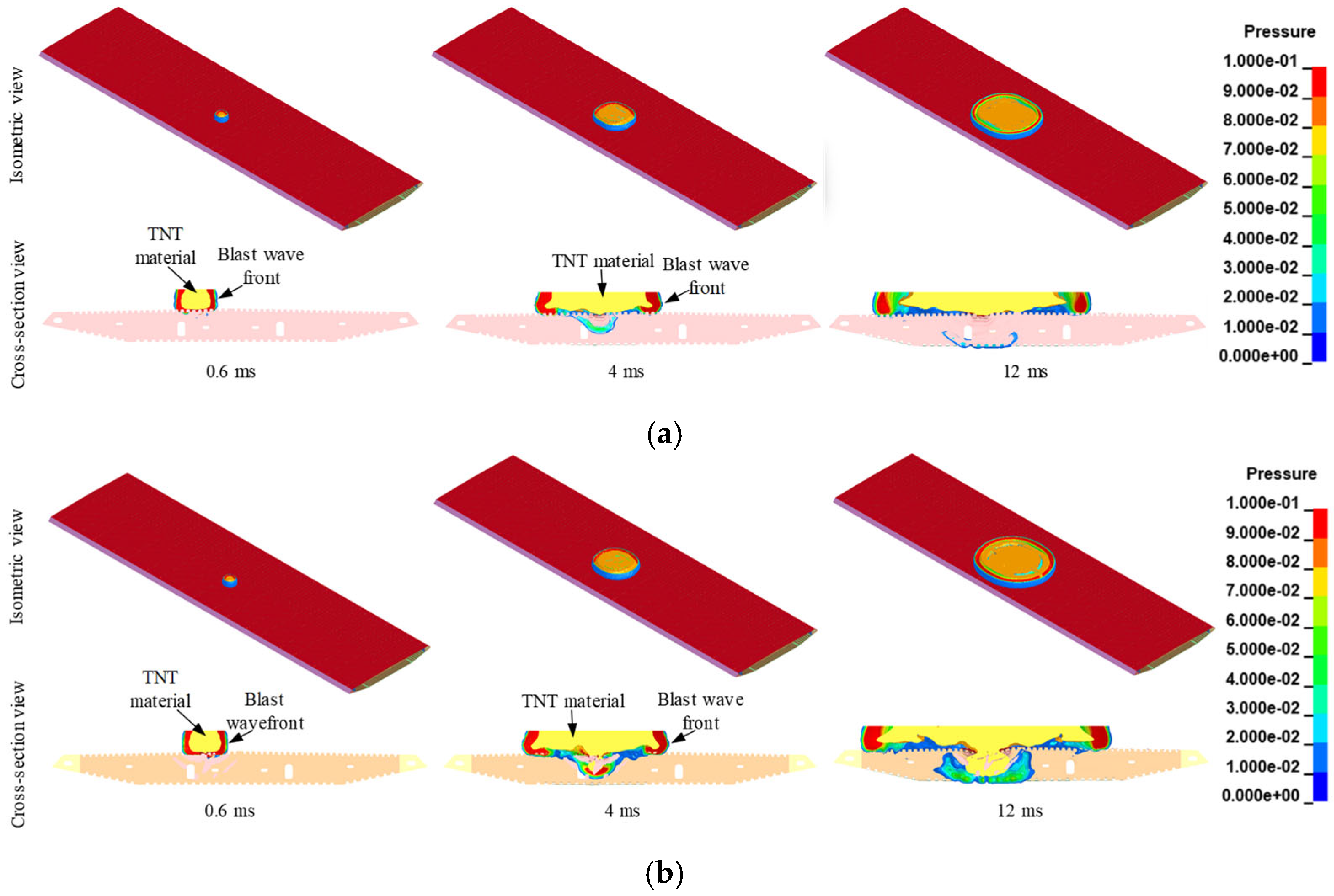
Figure 8 illustrates the pressure contours of blast wave propagation on the deck surface and within the steel box girder in Scenarios A–E, where the cross-section view corresponds to the plane containing the geometric center of the explosive charge. The propagation of blast waves can be categorized into three distinct regimes, including the free-field propagation, external propagation outside the box girder, and internal propagation within the box girder. For the free-field propagation, the blast wave propagates outward as a spherical wave, unobstructed by structural components. After the blast wave encounters the bridge surface, if the top plate remains intact, the blast wave is reflected into a hemispherical wave and continues to propagate outward. For occasions when the top plate experiences opening damage, some of the blast wave enters the interior chamber of the box girder, and is reflected by the top plate, bottom plate, diaphragms, and U-stiffeners, greatly amplifying the peak pressure, generating a complex reflected pressure field and causing excessive damage to the bridge structure. Notably, for Scenario A (smaller charge mass), the blast wave affects a limited area, inducing only localized damage. In contrast, Scenario E (larger charge mass) exhibits wave diffraction at the bridge deck edges, fully enveloping the deck and causing severe localized and global structural damage to the bridge structure.
Moreover, the spread velocity of the TNT material is slightly lower than that of the blast wavefront, because the blast wave is a supersonic compression wave, whose velocity is determined by the energy release and the properties of the medium it traverses. While the velocity of gaseous products of TNT is governed by the conservation of mass, momentum, and energy, which dictate that the material velocity of the gases (post-shock flow) is always lower than the blast wave velocity itself. At the same instant, the blast wave front with larger TNT masses travels faster, which can also be elucidated by the abovementioned mechanisms, i.e., larger TNT masses release higher energy.

3.3.2. Failure Mode

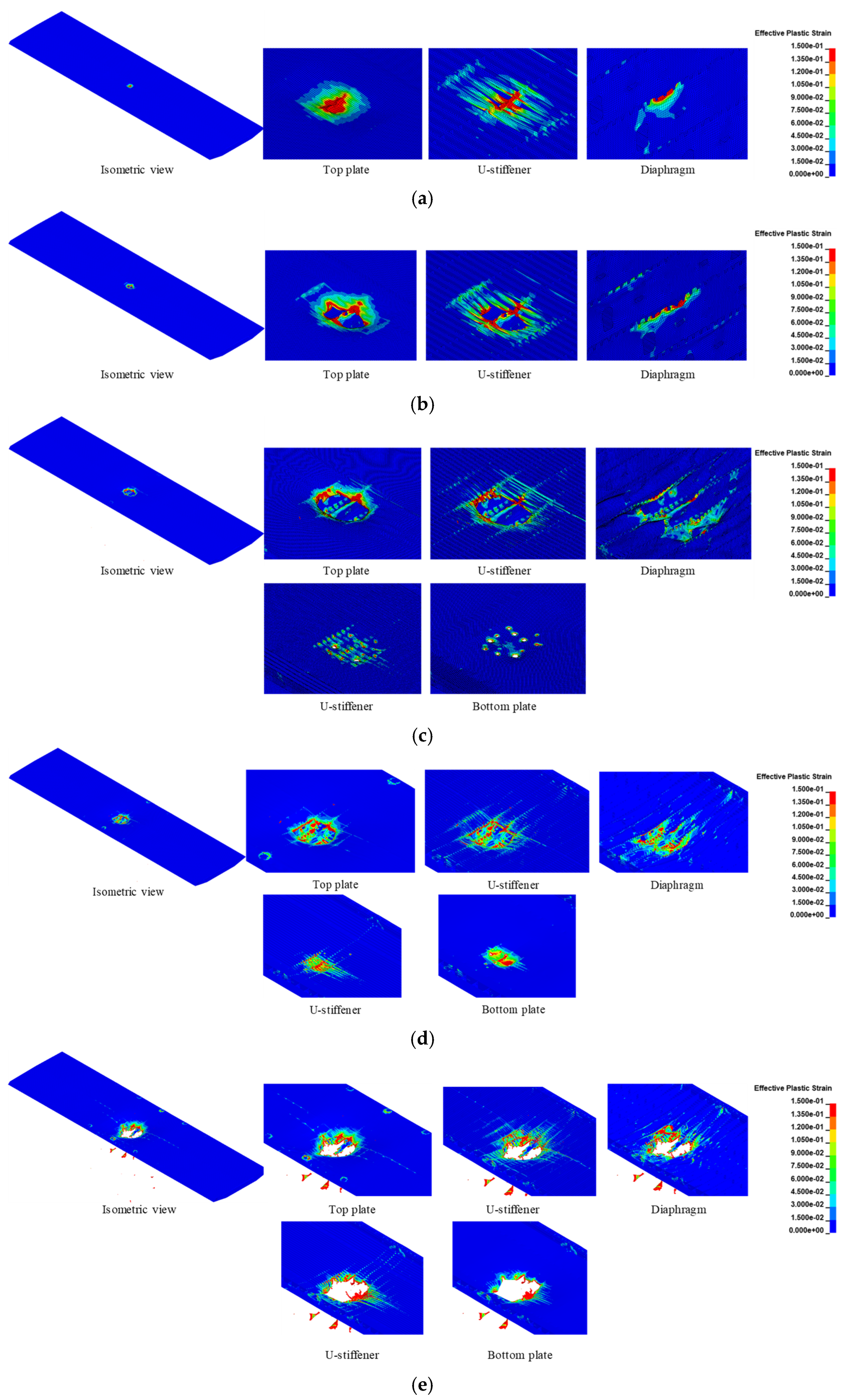
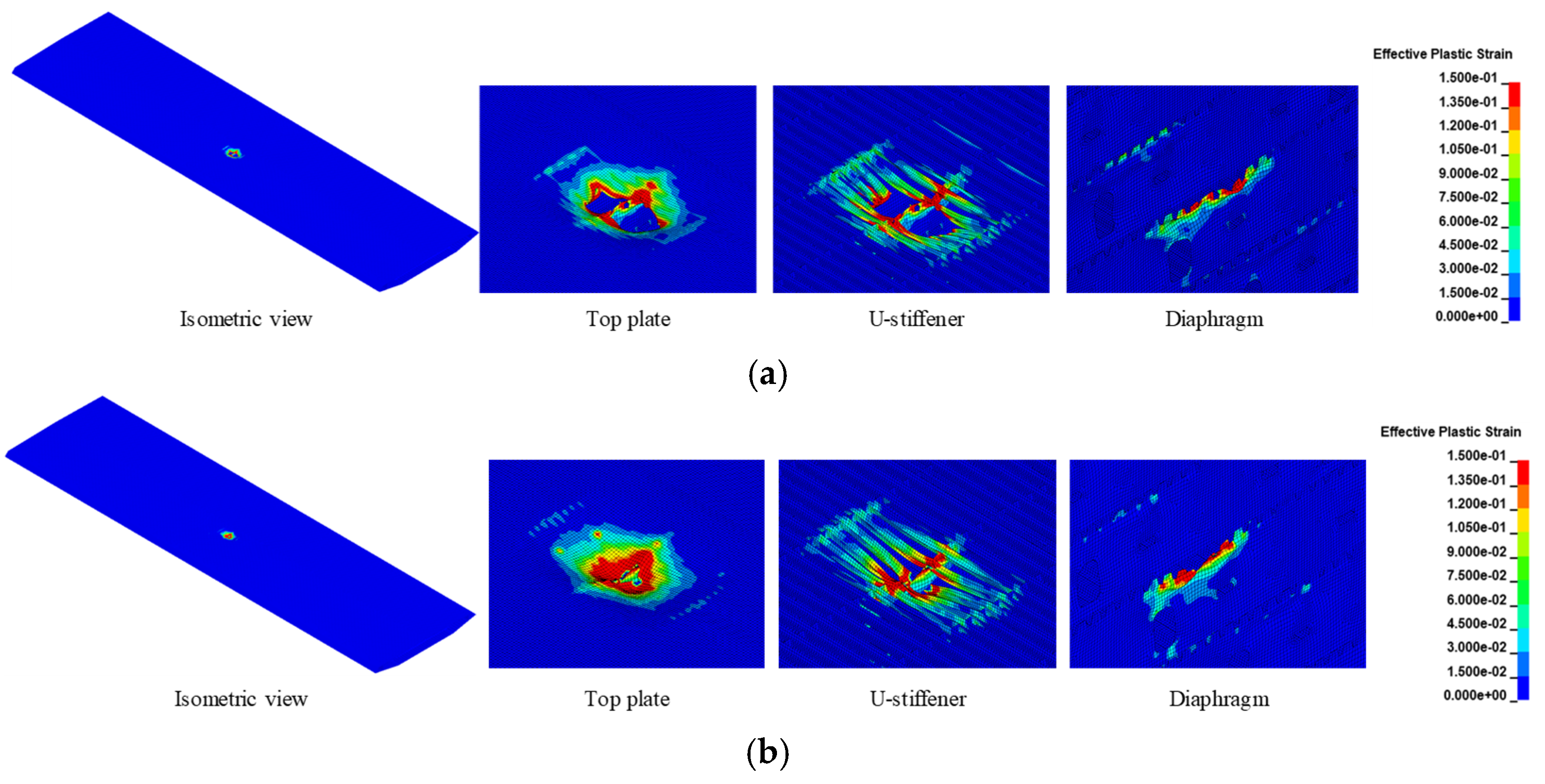
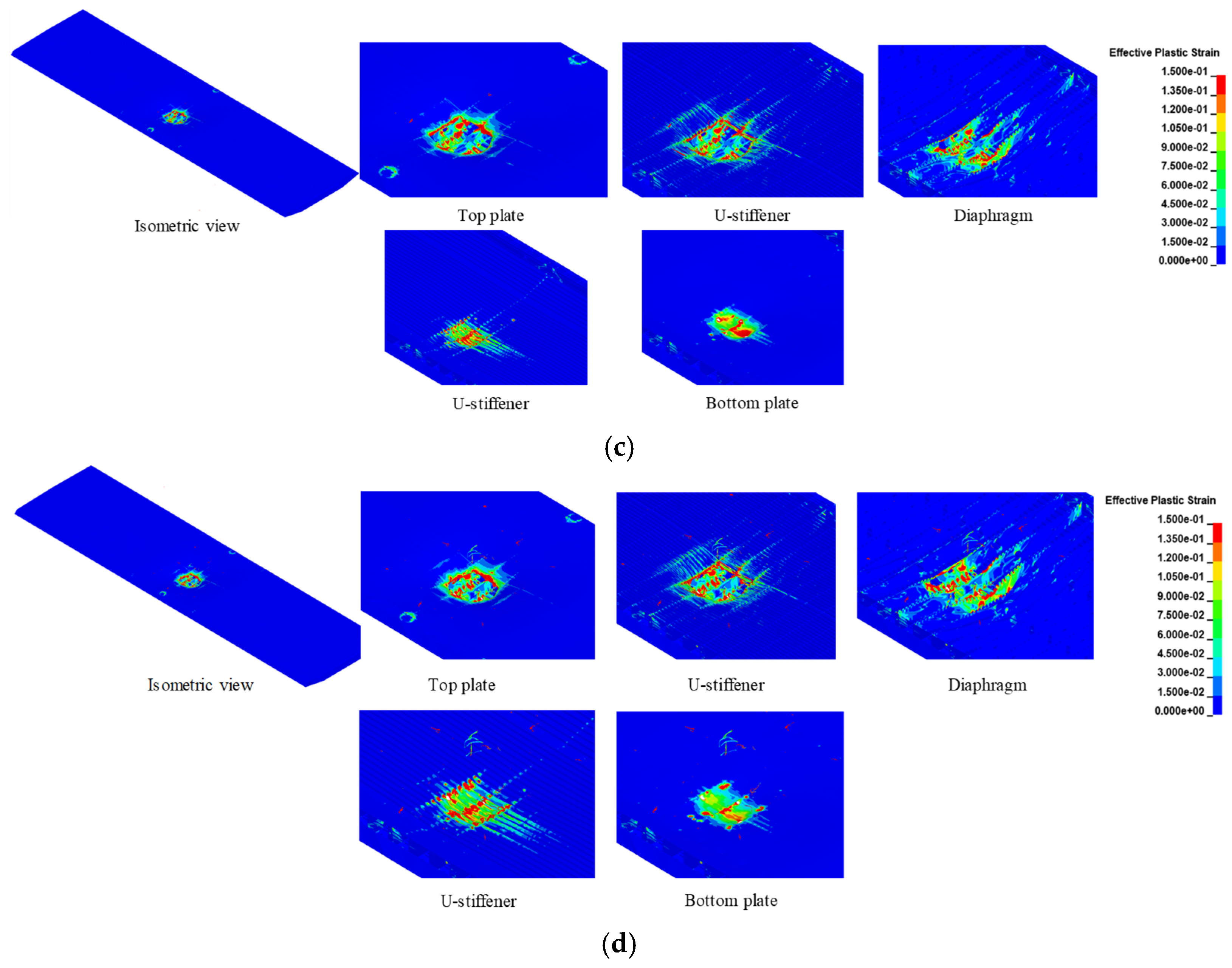
Figure 9 presents the damage contours of the steel box girder in different blast scenarios. It is evident that as the explosive charge increases, the top plate transitions from significant plastic deformations to openings, the diaphragms progress from localized plasticity to fracture, and the top plate U-stiffeners evolve from plastic deformation to rupture. The wind fairing stiffeners, located farther from the blast center and with smaller exposed surfaces, exhibit minor damage, showing only localized plasticity even in the worst-case scenarios. Besides, different from the findings derived by existing studies [19,20,21], new damage modes in the field of blast-resistant bridges were revealed, i.e., significant out-of-plane bending deformation and compressive buckling along their height of diaphragms, as well as bulging deformation of the bottom plate. The out-of-plane bending of diaphragms and bottom plate bulging primarily result from blast waves penetrating the steel box girder interior and expanding outward.
Regarding the bottom plate and its U-stiffeners, their failure modes correlate with the blast wave propagation range. When the blast wave does not penetrate the girder interior, the bottom plate and its U-stiffeners remain intact. However, when the wave propagates internally and directly impacts these components, both of them experience substantial plastic deformation, fracture, or even opening. Notably, debris from the top plate and its U-stiffeners caused by blast load can also induce secondary damage to the bottom plate and its U-stiffeners, as evidenced by the corresponding small openings in Scenarios C and D (Figure 9c,d).
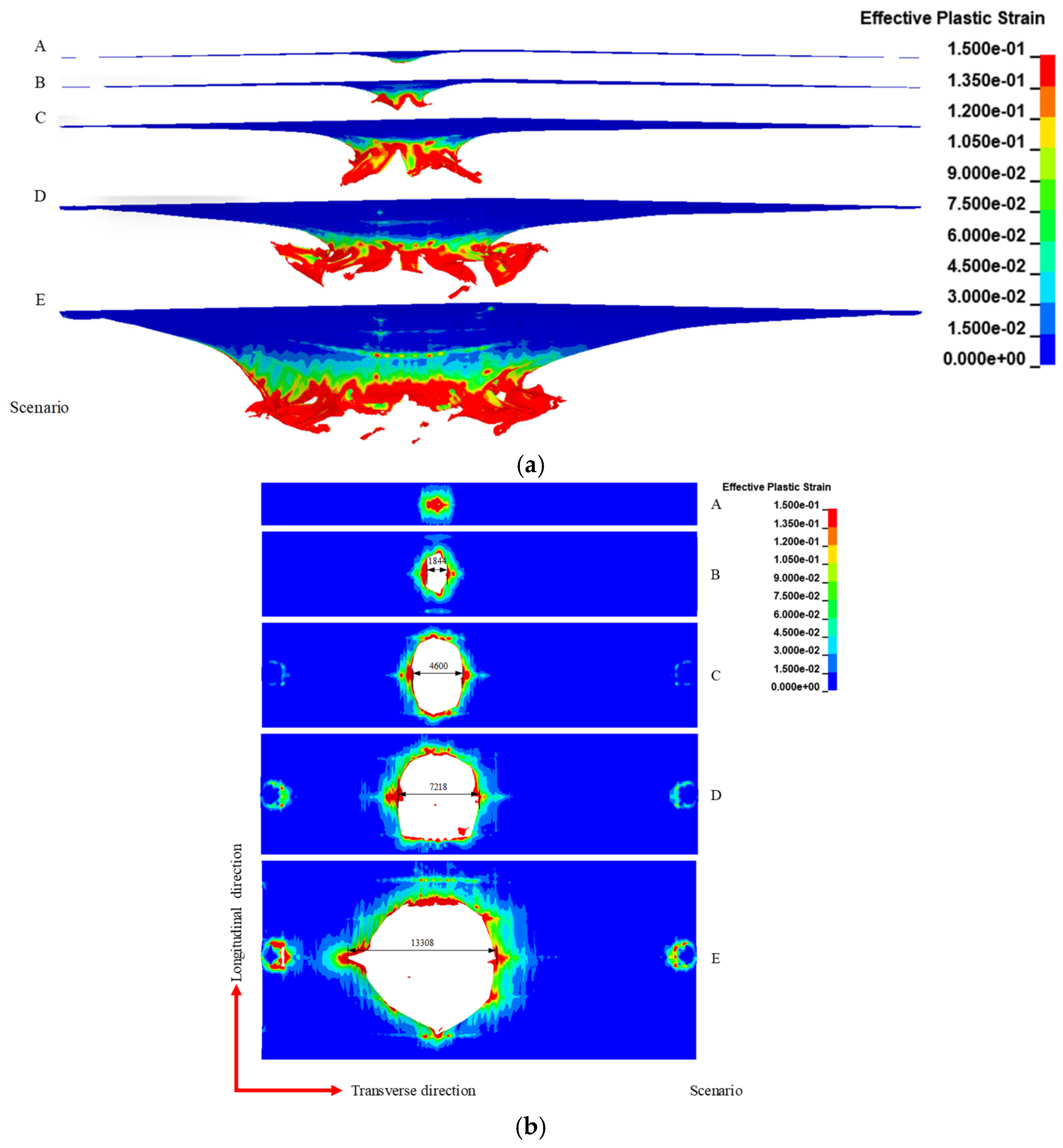
Figure 10 further presents the damage patterns of the top plate under vehicular explosions from both the side and top views. For explosion scenarios with smaller charge mass, the plastic deformation or perforation is highly localized, for example, Scenarios A and B. While the charge mass exceeds 1814 kg, almost the entire transverse span experiences large deformation and evident opening, i.e., Scenarios C–E. Besides, the damage range along the transverse direction in scenarios with a smaller charge mass is smaller than that along the longitudinal direction. The reason lies in that the multiple U-stiffeners below the top plate greatly hinder the propagation of the blast wave along the transverse direction, while the hindering effect along the longitudinal direction is limited. Moreover, under explosion with large charge mass, the anchorage region of the cable and the deck also exhibits plastic stress concentration, indicating that the bridge deck experiences both the local and global responses. Furthermore, to aid fast risk assessment, Figure 11 presents the quantitative comparison of the opening width against TNT mass.
Table 4 summarizes the failure modes of structural components under various blast scenarios. Unlike the common failure patterns reported in existing studies [9,10,11,12], large explosive charges induce significant out-of-plane bending deformation of diaphragms and compressive buckling along their height, as well as bulging deformation of the bottom plate. The blast wave-propelled debris of the top plate and U-stiffeners also causes secondary damage to the structures in the debris trajectory, i.e., a lot of small openings in the bottom plate in Scenarios C–E, see the third to last column in Table 4. The out-of-plane bending of diaphragms and bottom plate bulging primarily result from blast waves penetrating the steel box girder interior and expanding outward. The energy dissipation percentages of components under blast load are also provided in brackets in Table 4. For Scenarios A and B, the primary energy dissipation mechanism involves the large deformation of the top plate and top plate U-stiffeners, accounting for over 70% of total energy absorption, which aligns with findings reported by Jiang et al. [21]. However, in scenarios with larger explosive charges, energy dissipation is distributed across the top plate, top plate U-stiffeners, diaphragms, bottom plate, and bottom plate U-stiffeners, collectively exceeding 90% of total energy absorption, attributed to the opening damage mode of the bridge deck.
In summary, to guide the blast-resistant design of orthotropic steel bridge deck, it is suggested that for the explosion scenarios with smaller TNT masses, the stiffeners should be reinforced; for the explosion scenarios with larger TNT masses, the blast wave penetrates the girder interior through the blast-induced opening, and thus the diaphragms should be reinforced but left more prefabricated openings to release the blast energy.

3.3.3. Dynamic Response

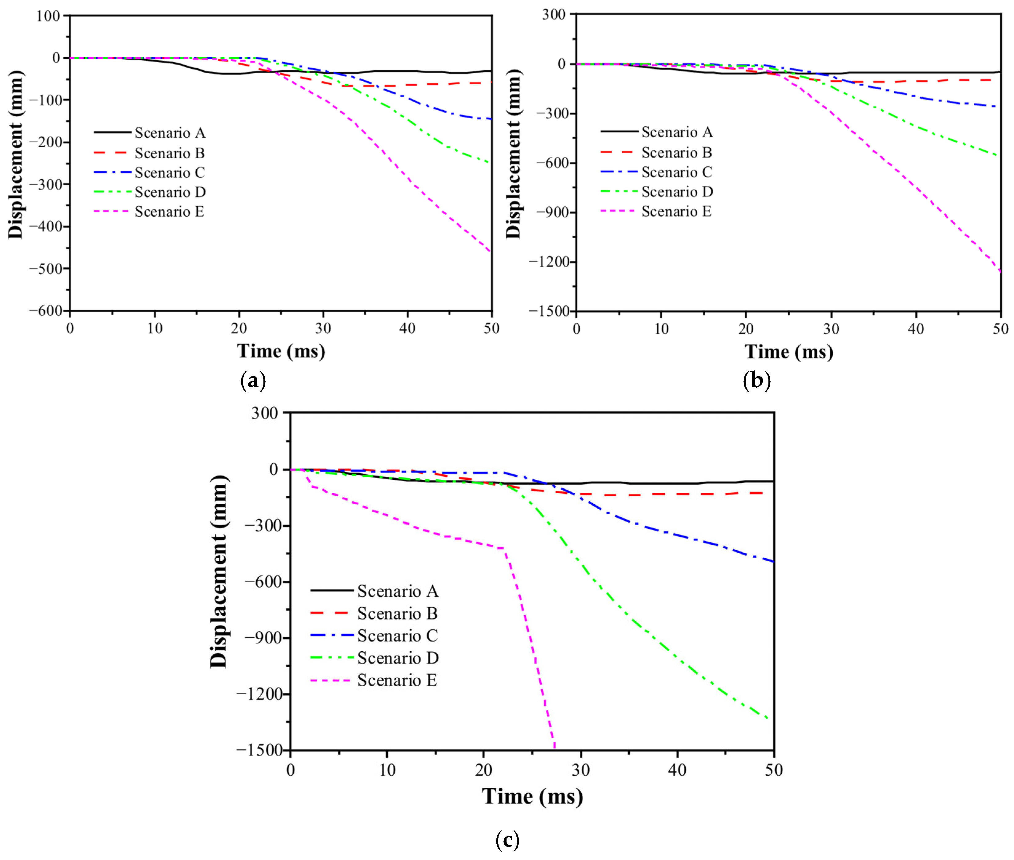
Figure 12 compares the blast-induced displacement-time histories at Gauges P1, P2, and P3 in the discussed scenarios. It can be seen that, in Scenarios A and B, the maximum displacements do not exceed 50 mm, and there is obvious oscillation of the corresponding curves, indicating that the bridge deck remains elastic state. Nonetheless, as the charge mass increases, the bridge deck experiences severe local damage and large plastic deformation, as indicated by the divergent displacement-time histories.

3.4. Further Discussion

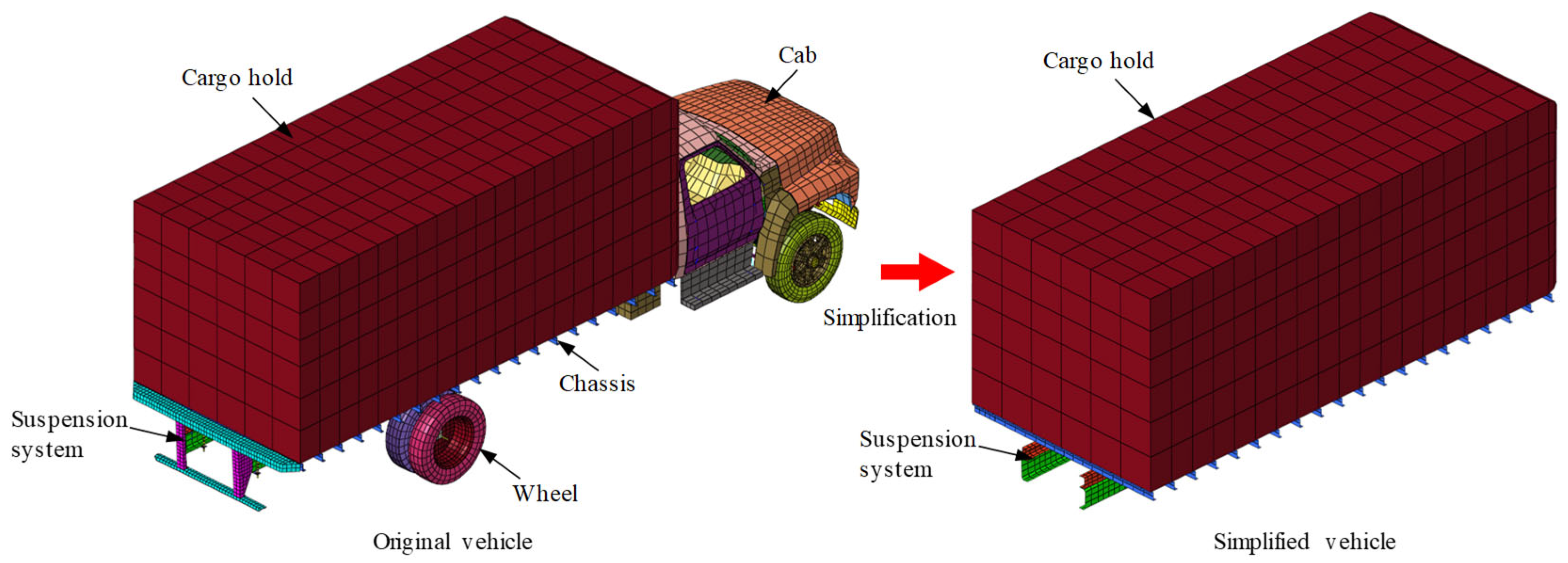
For actual vehicular bombs, the bomb is usually laid in the cargo hold of the vehicle. When the bomb is detonated, the explosion happens initially in a confined space, the blast wave as well as the detonation products rapidly expand outward and are reflected by the wall of the cargo hold. If the cargo hold is strong enough to constrain the explosion, the blast load will not threaten the bridge structure below. However, it is often the case that the cargo hold is easily destroyed, and the blast wave propagates outward, causing damage to the bridge structure. It is a critical issue whether to consider the confined effect of the vehicle shell or not. Though Hu et al. [22] and Zeng [23] numerically studied the influence of steel plate of the vehicle body on the blast wave propagation, and found that the pressure field distribution is changed, and the empirical formula for predicting overpressure in the free air domain is no longer applicable to vehicle-borne bomb explosions, the influence of vehicle shell on the dynamic behavior of the bridge deck under explosion of vehicular bomb is to be figured out. Considering that the vehicle model established by the National Crash Analysis Center (NCAC) [28] is extremely complex, the original one is simplified and only the cargo hold, suspension system are reserved, as shown in Figure 13. The cargo hold has dimensions of 5700 mm × 2500 mm × 2200 mm, and is made of mild steel plate with tensile strength of 155 MPa and thickness of 1.7 mm. TNT masses of 454 kg and 4536 kg are considered, and laid in the cargo hold, named as Scenarios B-V and D-V, respectively.
Figure 14 presents the comparisons of the blast wave propagation and TNT material distribution between scenarios without or with a vehicle shell. It can be found that, for TNT charge mass of 454 kg, the vehicle shell has a significant influence on the blast wave propagation concerning the morphology of the blast wavefront and the propagation velocity, i.e., the vehicle shell restrains the outward movement of the blast wavefront and reduces the blast propagation velocity. While for TNT charge mass of 4536 kg, the abovementioned influence is minor, and the reason lies in that compared with the huge explosion energy, the ratio of the dissipated energy by the vehicle shell to the total energy is relatively small.
Analogously, Figure 15 presents the damage profile comparisons of the bridge deck in Scenarios B, B-V, D, and D-V. For a scenario with a smaller TNT charge mass, the vehicle shell can effectively dissipate the explosion energy, and mitigate the blast-induced damage to the bridge, i.e., opening damage without a vehicle shell and only bulging damage with a vehicle shell. While for TNT charge mass of 4536 kg, the dissipated energy by the vehicle shell can be neglected, and thus the damage patterns of the bridge deck whether considering the vehicle shell or not are identical, i.e., opening at the top plate, fracture of the top U-stiffeners, buckling and bending failure of the diaphragm, severe plastic deformation of the bottom U-stiffeners and plate.
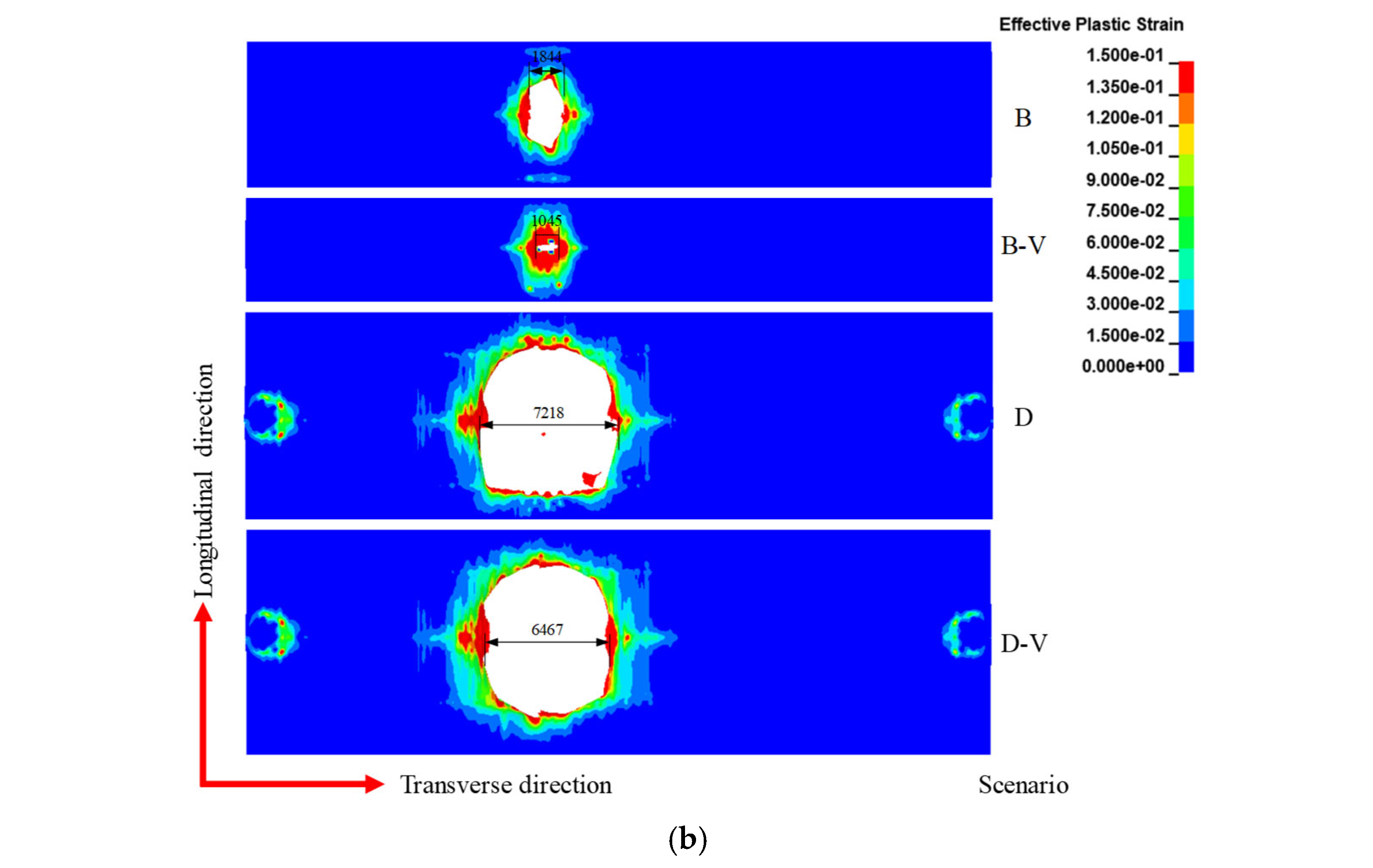
Figure 16 further presents the damage range and its dimensions of the top plate in these scenarios, intending to quantitatively evaluate the influence of the vehicle shell on the damage degree of the top plate. It can be seen that, for TNT charge masses of 454 kg and 4536 kg, the vehicle shell can reduce the transverse size of the top plate opening by 43.2% and 10.4%, respectively. Moreover, from the side view, the large plastic deformation of the top plate along the transverse direction can be observed, especially for Scenarios D and D-V, in which the bridge has lost its transportation capacity entirely. In Scenarios B and B-V, traffic transportation is influenced slightly for regions far from the detonation point in the transverse direction.
From perspective of the displacement response of the bridge deck, as seen in Figure 17, identical conclusions can be drawn. The vehicle shell is more effective in Scenario B-V, reducing the residual displacement of Gauges P1, P2, and P3 by about 26%, compared with that by about 5% in Scenario D-V.

4. Conclusions

A numerical simulation study was conducted to analyze the failure pattern of the orthotropic steel bridge deck under above-deck explosions. The main conclusions are as follows:
(1)
The steel box girder deck primarily exhibits localized damage under blast load. The extent of localized damage correlates with whether the blast wave penetrates the girder interior through openings in the top plate. Specifically, blast waves entering the girder interior cause more severe damage. Typical failure modes of the bridge deck were summarized, including the petal-shaped opening of the top plate, fracture, tearing or rupture of U-stiffeners, plastic deformation, out-of-plane bending, local buckling, and fracture of the diaphragms, and bulging deformation or openings of the bottom plate.
(2)
For explosion scenarios with smaller TNT masses, the top plate and U-stiffeners dominate energy dissipation, collectively accounting for over 70% of the total energy absorption by plastic deformation or damage, which aligns with conventional mechanisms observed in prior studies. For explosion scenarios with larger TNT masses, explosion energy is dissipated by plastic deformation and failure of multiple components-the top plate, top U-stiffeners, diaphragms, bottom plate, and bottom U-stiffeners, collectively contributing over 90% of total energy absorption. This shift arises because blast waves in these scenarios directly act on the bottom plate, inducing perforation failure.
(3)
For vehicular bomb explosion scenarios with charge mass of 454 kg, the vehicle shell can effectively reduce the damage range of the top plate by about 43.2%, and the displacement response by about 26%. Nevertheless, there is minor mitigation effect of the vehicle shell for explosion scenarios with TNT mass larger than 4536 kg.
It should be noted that the abovementioned conclusions are drawn based on specific explosion scenarios and this paper mainly focuses on the blast-resistant performance evaluation of steel box girder of a suspension bridge. In the future, parameter analysis concerning the detonation location, vehicle shell thickness and material, structural optimization, and protective measures can be performed for a better understanding of blast-induced dynamic behavior of large span bridges and corresponding design implications.

Author Contributions

Q.P.: writing-original draft; Q.W.: formal analysis; L.M.: conceptualization. All authors have read and agreed to the published version of the manuscript.

Funding

This project was funded by the National Natural Science Foundation of China (52308479), Natural Science Foundation of Hunan Province (2025JJ60296), National Natural Science Foundation of China (52408554), China Postdoctoral Science Foundation (2024M752415).

Data Availability Statement

Data will be made available on request.

Conflicts of Interest

The authors confirm that there are no conflicts of interest.

References

  1. Liu, Y.; Zhang, X.; Liu, R.; Chen, G. Design and mechanical properties of steel-UHPC lightweight composite decks. Adv. Civ. Eng. 2021, 2021, 8508795. [Google Scholar] [CrossRef]
  2. Worku, Z.; Liu, M.; Wang, X.; Sheng, G. Flexural behavior of orthotropic steel–LUHPC composite bridge decks: Experimental and numerical study. Materials 2025, 18, 2106. [Google Scholar] [CrossRef] [PubMed]
  3. Ma, L.L.; Wu, H.; Fang, Q.; Xu, J.P. Displacement-based blast-resistant evaluation for simply-supported RC girder bridge under below-deck explosions. Eng. Struct. 2022, 266, 114637. [Google Scholar] [CrossRef]
  4. Ma, L.L.; Wu, H.; Fang, Q. Damage mode and dynamic response of RC girder bridge under explosions. Eng. Struct. 2021, 243, 112676. [Google Scholar] [CrossRef]
  5. Remennikov, A.; Ngo, T.; Mohotti, D.; Uy, B.; Netherton, M. Experimental investigation and simplified modeling of response of steel plates subjected to close-in blast loading from spherical liquid explosive charges. Int. J. Impact Eng. 2017, 101, 78–89. [Google Scholar] [CrossRef]
  6. Remennikov, A.; Mentus, I.; Uy, B. Explosive breaching of walls with contact charges: Theory and applications. Int. J. Prot. Struct. 2005, 6, 629–647. [Google Scholar] [CrossRef]
  7. Henchie, T.F.; Yuen, S.; Nurick, G.N.; Ranwaha, N.; Balden, V.H. The response of circular plates to repeated uniform blast loads: An experimental and numerical study. Int. J. Impact Eng. 2014, 74, 36–45. [Google Scholar] [CrossRef]
  8. Yang, M.; Wu, H.B.; Wu, Y.; Xu, K.; Xie, P.; Li, M.Z.; He, Y.H. Experimental study on influence of explosion source explosion on steel plate under different contact conditions. J. Saf. Environ. 2022, 22, 1878–1884. (In Chinese) [Google Scholar]
  9. Han, L.; Yuan, J.F.; Zhang, Y.L.; Xu, Q.P.; Li, Z.R. Damage Characteristics of Fixed Rectangular Steel Plate under Close-in Explosion. Chin. J. Explos. Propellants 2021, 44, 225–232. (In Chinese) [Google Scholar]
  10. Yuen, S.C.K.; Nurick, G.N. Experimental and numerical studies on the response of quadrangular stiffened plates. Part I: Subjected to uniform blast load. Int. J. Impact Eng. 2005, 31, 55–83. [Google Scholar] [CrossRef]
  11. Langdon, G.S.; Yuen, S.C.K.; Nurick, G.N. Experimental and numerical studies on the response of quadrangular stiffened plates. Part II: Localised blast loading. Int. J. Impact Eng. 2005, 31, 85–111. [Google Scholar] [CrossRef]
  12. Yuen, S.; Nurick, G.N.; Langdon, G.S.; Iyer, Y. Deformation of thin plates subjected to impulsive load: Part III—An update 25 years on. Int. J. Impact Eng. 2017, 107, 108–117. [Google Scholar] [CrossRef]
  13. Yuen, S.C.K.; Langdon, G.S.; Nurick, G.N.; Pickering, E.G.; Balden, V.H. Response of V-shape plates to localised blast load: Experiments and numerical simulation. Int. J. Impact Eng. 2012, 46, 97–109. [Google Scholar] [CrossRef]
  14. Gan, L.; Zong, Z.; Lin, J.; Wu, T.; Chen, Z.; Chen, L. Damage mechanism of U shaped ribs stiffened steel flat plates subjected to close in explosion. Thin-Walled Struct. 2022, 179, 109656. [Google Scholar] [CrossRef]
  15. Gan, L.; Zong, Z.; Lin, J.; Chen, Y.; Xia, M.; Chen, L. Influence of U-shaped stiffeners on the blast-resistance performance of steel plates. J. Constr. Steel Res. 2022, 188, 107046. [Google Scholar] [CrossRef]
  16. Goe, M.D.; Matsagar, V.A.; Gupta, A.K. Dynamic Response of Stiffened Plates under Air Blast. Int. J. Prot. Struct. 2011, 2, 139–156. [Google Scholar] [CrossRef]
  17. Razak, N.S.A.; Alias, A.; Mohsan, N.M.; Masjuki, S.A. Numerical investigation of the failure of stiffened steel plates subjected to near-field blast loads. J. Fail. Anal. Prev. 2023, 23, 569–591. [Google Scholar] [CrossRef]
  18. Gan, L.; Zong, Z.H.; Li, M.H.; Qian, H. Dynamic response and failure mode of U shaped stiffener stiffened steel plate under blast loading. J. Southeast Univ. (Nat. Sci. Ed.) 2020, 50, 207–214. (In Chinese) [Google Scholar]
  19. Liu, Y.L.; Liu, Y.C.; Geng, S.B.; Wang, W.Y.; Xue, J.Y.; Liu, L. An experimental study on the local damage and influence factors of a steel box girder under explosive shock wave. J. Vib. Shock 2018, 37, 229–236. (In Chinese) [Google Scholar]
  20. Bai, Z.H. Investigation of Failure Mechanisms of Orthotropic Steel Bridge Decks Undern Terror Blast Loading. Master’s Thesis, National University of Defense Technology, Changsha, China, 2010. (In Chinese). [Google Scholar]
  21. Jiang, Z.G.; Bai, Z.H.; Yan, B.; Zhu, X.-B. Numerical simulation for response of a steel box girder deck to blast loading. J. Vib. Shock 2012, 31, 77–81. (In Chinese) [Google Scholar]
  22. Hu, Z.J.; Tang, X.H.; Fang, J.Q. Analysis of Pressure Field and Response for Concrete Bridges Under Close Blast Loading. China J. Highw. Transp. 2014, 27, 141–167. (In Chinese) [Google Scholar]
  23. Zeng, Z. Study of Pressure Distribution and Damage Effect for Concrete Bridges Subjected to Vehicle-Mounted Blast Loads. Master’s Thesis, Wuhan University of Technology, Wuhan, China, 2016. (In Chinese). [Google Scholar]
  24. FEMA-428; Buildings and Infrastructure Protection Series, Primer to Design Safe School Projects in Case of Terrorist Attacks and School Shootings. Department of Homeland Security, Science and Technology Directorate, Infrastructure Protection and Disaster Management Division: Washington, DC, USA, 2012.
  25. Livermore Software Technology Corporation. LS-DYNA Keyword User’s Manual; Livermore Software Technology Corporation: Livermore, CA, USA, 2022. [Google Scholar]
  26. Jiangsu Provincial Transportation Planning and Design Institute Co., Ltd.; China Railway Major Bridge Reconnaissance; Design Institute Co., Ltd.; Tongji University Architectural Design and Research Institute. Design of Construction Drawings for the Main Bridge of Taizhou Yangtze River Highway Bridge, Volume II, First Part of the Main Bridge (1)-Stiffening Girder; Jiangsu Provincial Transportation Planning and Design Institute Co., Ltd.: Nanjing, China, 2009. (In Chinese) [Google Scholar]
  27. Lou, F. Experimental Study on Blast Resistance of Prestressed Concrete Continuous Beams. Master’s Thesis, Southeast University, Nanjing, China, 2018. (In Chinese). [Google Scholar]
  28. Mohan, P.D.; Marzougui; Kan, C.D.S. Validation of a single unit truck model for roadside hardware impact. Int. J. Veh. Syst. Model. Test. 2007, 2, 1–15. [Google Scholar] [CrossRef]
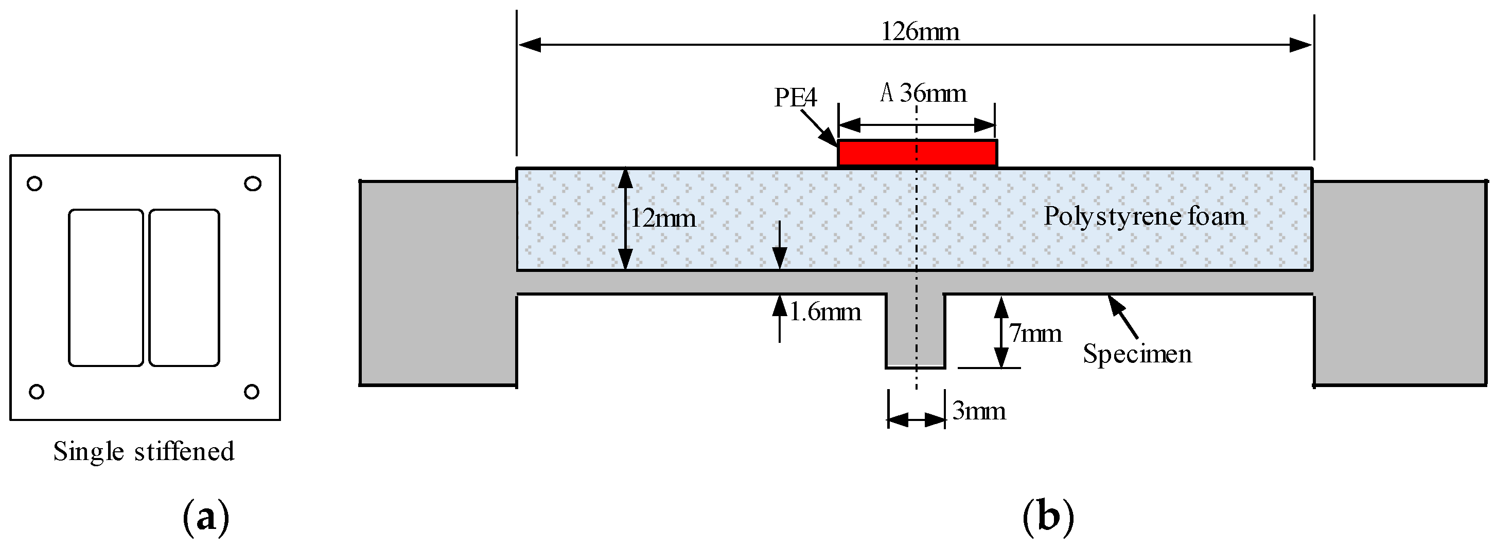
Figure 1. Schematic diagram of the explosion test [11]: (a) single-stiffened steel plate; (b) test setup.
Buildings 15 03210 g001
Figure 2. FE model.
Figure 2. FE model.
Buildings 15 03210 g002
Figure 3. Comparisons of predicted and experimental damage mode of single-stiffened steel plates under explosion with PE4 of (a) 4 g; (b) 4.5 g; (c) 5 g; (d) 7 g [11].
Buildings 15 03210 g003aBuildings 15 03210 g003b
Figure 4. Comparisons of predicted and experimental central deflection of steel plates under explosion with PE4 of (a) 4 g; (b) 4.5 g; (c) 5 g; (d) 7 g [11].
Buildings 15 03210 g004
Figure 5. Standard cross-section of steel box girder section [26] (unit: mm).
Buildings 15 03210 g005
Figure 6. FE model of prototype bridge under above-deck explosion.
Buildings 15 03210 g006
Figure 7. Schematic diagram of location of lane and detonation (unit: mm).
Buildings 15 03210 g007
Figure 8. Pressure contours of blast wave propagation in Scenarios: (a) A; (b) B; (c) C; (d) D; (e) E.
Buildings 15 03210 g008aBuildings 15 03210 g008b
Figure 9. Damage contours of the bridge deck in Scenarios: (a) A; (b) B; (c) C; (d) D; (e) E.
Buildings 15 03210 g009
Figure 10. Comparisons of the blast-induced opening in the top plate in (a) side view; (b) top view (unit: mm).
Buildings 15 03210 g010
Figure 11. Relationship between the opening width and TNT mass.
Buildings 15 03210 g011
Figure 12. Displacement comparisons at Gauges: (a) P1; (b) P2; (c) P3.
Buildings 15 03210 g012
Figure 13. Simplification of the vehicle developed by NCAC [28].
Buildings 15 03210 g013
Figure 14. Comparisons of the blast wave propagation in Scenarios: (a) B; (b) B-V; (c) D; (d) D-V.
Buildings 15 03210 g014aBuildings 15 03210 g014b
Figure 15. Comparisons of the damage patterns of bridge deck in Scenarios: (a) B; (b) B-V; (c) D; (d) D-V.
Buildings 15 03210 g015aBuildings 15 03210 g015b
Figure 16. Comparisons of the blast-induced opening in the top plate in (a) side view; (b) top view (unit: mm).
Buildings 15 03210 g016aBuildings 15 03210 g016b
Figure 17. Comparisons of the blast-induced displacement at Gauges: (a) P1; (b) P2; (c) P3.
Buildings 15 03210 g017
Table 1. Parameters of material models and EOSs [14].
Air (*MAT_NULL&*EOS_LINEAR_POLYNOMIAL)
Initial densityInitial energy E0Pressure cutoffDynamic viscosity coefficientC0, C1, C2, C3, C6C4, C5
1.29 kg/m32.5 × 105 J/m30000.4
TNT (*MAT_HIGH_EXPLOSIVE_BURN & *EOS_JWL)
Initial densityDetonation velocity DBurst pressure PCJABR1R2 ω E0
1630 kg/m36930 m/s21 GPa373.8 GPa3.747 GPa4.150.90.356 × 109 J/m3
Table 2. Thickness of steel plate for steel box girder component [26].
ComponentThickness (mm)
Top plate16
Bottom plate10
Vertical web14
Top/bottom U-stiffener6
Top/bottom inclined plate of bridge wind fairing8
Diaphragm10/14
Diaphragm of bridge wind fairing10/14
Table 3. Types of threats [24].
ThreatBuildings 15 03210 i001(A)Buildings 15 03210 i002(B)Buildings 15 03210 i003(C)Buildings 15 03210 i004(D)Buildings 15 03210 i005(E)
TNT mass (kg)2274541814453613,608
Burst height (m)0.760.831.021.201.51
Table 4. Damage mode and energy dissipation of each component.
ScenarioTop PlateTop U-StiffenerWind Fairing StiffenerWebWind Fairing DiaphragmDiaphragm D1Diaphragm D2Bottom PlateBottom U-StiffenerInclined Plate on the Wind Fairing
AOpening with dimensions of about 0.1 m × 0.14 m, region connected to the diaphragm experiences large deformation (36.8%)3 U-stiffeners’ edges are torn and undergo significant plastic deformation (32.9%)Intact (0.3%)Local plasticity (0.9%)Intact (0.0%)Local plasticity (4.9%)Curved incision fracture (20.0%)Intact (2.7%)Intact (1.2%)Intact (0.3%)
BPetal-shaped opening with dimensions of about 1.8 m × 3.4 m (45.3%)3 U-stiffeners fractured and 2 U-stiffeners experienced significant plastic deformation (29.6%)Intact (0.2%)Local plasticity (1.5%)Intact (0.0%)Local plasticity (5.3%)Curved incision fracture (20.0%)Intact (2.5%)Intact (0.8%)Intact (0.2%)
CPetal-shaped opening with dimensions of about 4.6 m × 6.5 m (38.1%)7 U-stiffeners fractured and 4 U-stiffeners experienced significant plastic deformation (23.7%)Local plasticity (0.3%)Local flexure (1.6%)Intact (0.0%)2 diaphragms exhibit significant plastic deformation and another 2 diaphragms exhibit out-of-plane bending (13.8%)Curved incision fracture, 30% buckling of the diaphragm along the height direction (9.5%)9 openings with diameters ranging from 0.3 m to 0.6 m (7.1%)Local opening (5.6%)Intact (0.3%)
DPetal-shaped opening with dimensions of about 7.2 m × 7.3 m, plastic deformation near the cable anchorage region (31.5%)12 U-stiffeners fractured and 4 U-stiffeners experienced significant plastic deformation (19.7%)Flexural deformation (0.3%)Local plasticity (1.7%)Intact (0.0%)Arc-shaped incision fracture, large plastic deformation, out-of-plane bending, and 38% buckling of the diaphragm along the height direction (16.0%)Curved incision fracture, large plastic deformation, out-of-plane bending, and 40% buckling of the diaphragm along the height direction (10.1%)9 openings with diameters ranging from 0.3 m to 0.5 m, and 2 bulges (11.3%)5 U-stiffeners fractured and 2 U-stiffeners experienced significant plastic deformation (8.9%)Local plasticity (0.4%)
EPetal-shaped opening with dimensions of about 13.3 m × 10.9 m, tearing near the cable anchorage region (25.6%)18 U-stiffeners fractured and 4 U-stiffeners experienced significant plastic deformation (14.8%)Flexural deformation (0.3%)Local plasticity (1.6%)Intact (0.0%)Curved incision fracture, large plastic deformation, out-of-plane bending, and fracture of 2 diaphragms (15.5%)Complete fracture of 1 diaphragm, localized plasticity at the ends of 4 diaphragms (6.1%)Petal-shaped opening with dimensions of 11.8 m × 12.2 m (21.0%)15 U-stiffeners fractured (14.6%)Local plasticity (0.4%)
Disclaimer/Publisher’s Note: The statements, opinions and data contained in all publications are solely those of the individual author(s) and contributor(s) and not of MDPI and/or the editor(s). MDPI and/or the editor(s) disclaim responsibility for any injury to people or property resulting from any ideas, methods, instructions or products referred to in the content.