Abstract
This study investigates the axial compressive behaviour of rectangular concrete specimens confined with low-cost Glass Chopped Strand Mat (GCSM) sheets. While the GCSM has been explored in other contexts, this is the first study specifically investigating its effects on rectangular concrete specimens. A total of 24 specimens were tested, grouped by different unconfined concrete strengths. Each group included unconfined specimens and GCSM-confined specimens wrapped with 2, 3, and 4 layers. The results demonstrate that GCSM confinement significantly enhances both compressive strength and ductility, particularly in low-strength concrete, where normalized gains in strength and strain exceeded 50% and 160%, respectively. The post-peak modulus decreased with increasing confinement ratio, indicating improved energy dissipation and delayed failure. Additionally, experimental elastic modulus values showed good agreement with ACI 318 predictions. Analytical models were developed to predict peak strength, peak strain, and post-peak modulus as functions of confinement pressure, achieving excellent correlation with experimental data (R2 > 0.98).
1. Introduction
The need to strengthen and retrofit deteriorating or underperforming reinforced concrete (RC) structures has gained substantial attention due to the rise in service load demands, environmental deterioration, and seismic hazards. This increasing demand for structural retrofitting stems from the fact that a significant proportion of existing RC structures are approaching or have exceeded their intended service life, exhibiting reduced load-bearing capacity, increased susceptibility to cracking, and diminished ductility. In many developing regions, budgetary and material constraints further limit the use of high cost strengthening techniques. Addressing these challenges requires alternative solutions that are not only structurally efficient but also economically viable and sustainable. Among the various strengthening techniques, externally bonded fibre-reinforced polymer (FRP) systems have emerged as one of the most effective solutions to enhance the load-carrying capacity, ductility, and overall performance of RC members [1,2]. FRP composites such as carbon (CFRP), aramid (AFRP), and glass (GFRP) fibres have been widely used due to their high tensile strength, low weight, and corrosion resistance [3,4]. However, their widespread application is often hindered by high material and installation costs, as well as labour intensive surface preparation and bonding requirements [5,6]. In light of these limitations, alternative low-cost composite materials are being explored. Among these, Glass Chopped Strand Mat (GCSM) emerges as a particularly promising alternative, combining the mechanical benefits of fibre confinement with the environmental advantages of low-cost composite materials. GCSM comprises randomly oriented E-glass fibres held together by a resin-compatible binder. GCSM sheets exhibit quasi-isotropic mechanical behaviour due to their non-directional fibre arrangement, offering an economic and mechanically balanced alternative to traditional unidirectional FRPs [7,8]. Its compatibility with various resins, ease of application through hand lay-up methods, and potential to be anchored using mechanical systems make it a promising candidate for structural strengthening, particularly in low-resources settings [9]. Recent studies have demonstrated the efficiency of GCSM in enhancing the structural behaviour of concrete members under shear and axial loads. Joyklad et al. [7] evaluated the axial performance of concrete specimens containing brick aggregates wrapped in GCSM layers and found that peak strength and ultimate strain increased significantly with up to four layers of wrapping. Similarly, Lam et al. [10] used GCSM sheets for shear strengthening of RC deep beams, observing strength gains of over 100% depending on the configuration and anchorage system used. Further, Thansirichaisree et al. [8] applied GCSM to shallow RC beams and recorded substantial improvements in energy dissipation, deflection capacity, and failure ductility. These studies confirm the promising role of GCSM as a strengthening material.
In addition to strength and ductility improvements, GCSM-confined members have shown superior performance in energy absorption and crack control, particularly under cyclic or dynamic loading scenarios [11]. The multi-directional nature of fibre dispersion in GCSM allows for stress redistribution across the surface, effectively enhancing confinement even in irregular or discontinuous sections [12]. Moreover, studies have highlighted that the use of GCSM does not necessitate expensive curing regimes or precision placement as in the case of CFRP laminates, thereby offering ease of field application [13]. Recent investigations into GCSM application on columns, slabs, and beams have shown potential for both axial and flexural enhancement, opening new avenues for structural resilience upgrading in older buildings [8,14]. Despite these encouraging findings, most existing research has focused on either cylindrical specimens or beams made with recycled or brick aggregate concrete. Cylindrical and square specimens benefit from a uniform distribution of hoop stresses under confinement, allowing for more efficient activation of the external jacket [15,16]. However, real-world structures often include rectangular columns and elements with sharp corners that induce stress concentrations, reduce effective confinement, and increase the likelihood of delamination or premature failure [17,18]. These geometric effects impair the confinement efficiency and challenge the applicability of idealized circular specimen data to rectangular structural elements. In practical applications, rectangular cross-sections are prevalent due to architectural, space, and design constraints [19,20]. Yet, the unique confinement behaviour of these geometries under external wrapping remains underexplored. The stress flow in rectangular sections is less uniform, and the corner regions often require special treatment, such as chamfering, to avoid local failures and delamination [21]. Experimental studies have shown that curvature radius at corners significantly affects the confinement effectiveness of FRP and GCSM jackets, and thus proper profiling is crucial for maximizing performance [22]. Furthermore, numerical simulations reveal that rectangular sections often underperform in terms of confinement efficiency due to reduced transverse stiffness, making physical testing vital for validation [23]. The choice to focus exclusively on rectangular columns in this study stems from their widespread use in real-world buildings due to architectural and spatial constraints, despite their reduced confinement efficiency compared to circular or square sections. While beams are also critical structural members, columns are primary load-carrying elements whose failure can directly compromise structural stability, making them a priority for retrofitting research. This study seeks to address this gap by investigating the confinement behaviour of rectangular concrete specimens made with natural aggregates and strengthened using low-cost GCSM sheets. Three concrete strength levels—20 MPa, 30 MPa, and 40 MPa—were selected to represent low, medium, and high strength categories typically encountered in field applications. Each strength group included specimens with no confinement and those wrapped with two, three, and four GCSM layers. This matrix enables a systematic evaluation of both the effect of concrete strength and the incremental benefit of additional GCSM layers.
By employing natural aggregates instead of recycled brick aggregates, the present study aims to provide results that are more directly relevant to contemporary structural concretes used in real construction [24]. Unlike existing work, this investigation captures a range of strength levels, facilitating potential development of analytical confinement models or modifications to existing design equations [25]. The novelty of this study lies in its focus on rectangular specimens using natural aggregates and variable concrete strengths—a configuration not addressed in prior literature, which largely focused on brick-based concrete or ideal geometries. In addition to evaluating the influence of concrete strength and the number of GCSM layers, the study also investigates strain development and failure modes under axial loading. Strain values were derived from displacement measurements recorded during compression testing, and failure modes, including cracking patterns and delamination, were documented through direct observation and photographic evidence. The outcomes of this research have the potential to inform modifications to practical design guidelines by providing experimental evidence on the confinement performance of GCSM in rectangular columns. These findings could support the incorporation of GCSM retrofitting provisions into future structural codes, particularly for applications in cost-sensitive and resource-limited contexts. The findings aim to provide benchmark data for future design formulations involving GCSM, promote its acceptance in structural guidelines, and offer an accessible strengthening solution for infrastructure in developing regions.
2. Experimental Programme
2.1. Specimens Details
A total of 24 rectangular concrete specimens were prepared and systematically categorized into three primary groups based on their target compressive strengths: Low Strength (LS—20 MPa), Medium Strength (MS—30 MPa), and High Strength (HS—40 MPa). Each group consisted of four types of specimens: unconfined control specimens (0 layers), and specimens confined with 2, 3, and 4 layers of GCSM sheets. Each configuration was repeated twice to ensure consistency and accuracy in the experimental results, leading to a total of eight specimens per group and twenty-four specimens in the entire study. All specimens were cast using rectangular steel moulds with dimensions of 100 mm × 200 mm in cross-section and 300 mm in height, as illustrated in Figure 1. The sharp corners were rounded off to a 13 mm radius in accordance with ACI 440.2R-17 [23] to improve the efficiency of the FCSM wraps by reducing the stress concentrations near the sharp corners. It is further stated that 13 mm is the minimum corner radius required by ACI 440.2R-17 [23]. All specimens were subjected to axial compression until failure in order to analyze improvements in compressive strength and ductility due to GCSM confinement. A systematic labelling scheme was adopted for easy identification of each specimen. The specimen ID comprised two components: the first denoting the concrete strength level and the second indicating the number of GCSM layers used for confinement. The suffixes “Con,” “2GCSM,” “3GCSM,” and “4GCSM” referred to the number of GCSM layers—0, 2, 3, and 4, respectively. For instance, a specimen ID labelled “LS-2GCSM” represents the low-strength concrete specimen confined with two GCSM layers, whereas specimen ID “HS-Con” refers to the unconfined high-strength control specimen having 0 layers of GCSM. A summary of the complete experimental programme, including all specimen IDs, concrete strength levels, and GCSM configurations, is provided in Table 1.
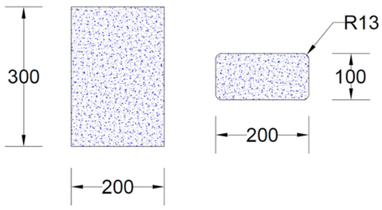
Figure 1.
Typical specimen geometry (units in mm).

Table 1.
Detailed categorization of test matrix.
2.2. Material Properties
The concrete used in this study was produced using natural aggregates, Ordinary Portland Cement, and river sand. The coarse aggregates consisted of well-graded crushed natural stones, ranging in size from 5 mm to 20 mm, exhibiting angular shape, good interlock, and high mechanical interlock. Fine aggregates were obtained from clean river sand, conforming to the requirements of ASTM C33 [26]. The gradation of fine aggregates complied with ASTM C33 specifications, and the particle size distribution curve is presented in Figure 2. The physical properties of the aggregates were determined in accordance with standard testing procedures. The coarse natural aggregates had a specific gravity of 2.65, bulk density of 1600 kg/m3, water absorption of 0.8%, and Los Angeles abrasion value of 25%. The fine aggregates exhibited a fineness modulus of 2.6, specific gravity of 2.60, and water absorption of 1.1%. These values ensured that the concrete mix, maintained workability and long-term durability across all three strength levels: 20 MPa, 30 MPa, and 40 MPa.
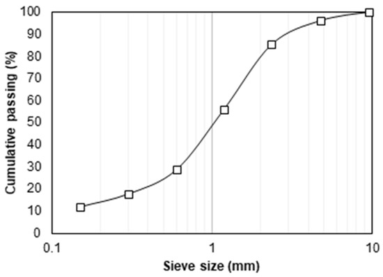
Figure 2.
Gradation curve of fine aggregates as per ASTM C33.
The external confinement material used in this study was GCSM, which is a low-cost, fibre-reinforced composite widely known for its adaptability in structural strengthening applications. GCSM is composed of short, randomly oriented E-glass fibres that are uniformly distributed and held together using a resin-compatible binder. This configuration imparts near-isotropic mechanical behaviour and enables the mat to resist multi-directional stresses, making it particularly effective for confinement applications on non-circular or geometrically irregular concrete sections. The glass fibres used in GCSM typically have a length of 50 mm, which ensure sufficient fibre overlaps and stress transfer within the matrix. The GCSM employed had a uniform thickness of 0.5 mm and density of 600 g/m2, allowing for ease of handling during wrapping procedures without compromising structural efficiency. The mat was provided in continuous rolls with a width of 1.0 m, which allowed for seamless application around the specimen surfaces. The mechanical properties of GCSM include an ultimate tensile strength of 180 MPa and a modulus of elasticity of 7470 MPa, as determined using standard tensile testing protocols in accordance with ASTM D3039M-08 [27].
The bonding agent used in conjunction with GCSM was a two-part epoxy resin system, mixed in a 2:1 (resin: hardener) volume ratio to achieve an optimum balance between viscosity and bonding strength. This epoxy ensured strong adhesion between the concrete surface and the GCSM layers, as well as among successive mat layers in multi-wrap configurations. Proper impregnation of the mat with resin during application is critical to ensure full engagement of the fibres during load transfer and to eliminate potential air gaps that could compromise the integrity of the composite shell.
2.3. Preparation of Specimens
The concrete mix design for each target strength category was developed using standard guidelines, and the constituent quantities are presented in Table 2. The proportions were selected to achieve target compressive strengths of 20 MPa, 30 MPa, and 40 MPa at 28 days. The corresponding water–cement ratios were 0.55 for low-strength concrete, 0.41 for medium-strength concrete, and 0.36 for high-strength concrete. No admixture was used to improve the workability of the concrete mix. These mixes were prepared using Ordinary Portland Cement, natural coarse aggregates, river sand as fine aggregates, and drinking water. The materials were mixed in a tilting drum mixer to ensure uniformity. Concrete was poured into pre-oiled steel moulds in three layers, with each layer compacted using a vibrating table. After demoulding at 24 h, all specimens were placed in a curing tank and maintained under water for a period of 28 days to allow sufficient hydration and strength gain. After curing, the specimens were removed from the tank, surface-dried, and prepared for wrapping. The surface preparation involved light abrasion using sandpaper followed by brushing to remove dust and loose particles, ensuring a clean and slightly roughened surface to promote epoxy adhesion. The epoxy system, mixed in a volume ratio of 2:1 (resin: hardener), was applied to the prepared surface using a brush. This was a two-part structural epoxy resin system, selected for its compatibility with GCSM and its ability to ensure strong adhesion between the concrete surface and successive mat layers. GCSM sheets were then wrapped manually using the hand lay-up method. Each sheet was cut to match the specimen height with an additional 100 mm overlap to ensure continuity. A roller was used to firmly press each layer against the concrete, eliminating air bubbles. For specimens requiring multiple layers, the same procedure was repeated with fresh epoxy resin between the layers. The wrapped specimens were left to cure in ambient conditions for 48 h to ensure proper hardening of the epoxy and effective bonding of the GCSM before testing (Figure 3).

Table 2.
Concrete mix proportions.
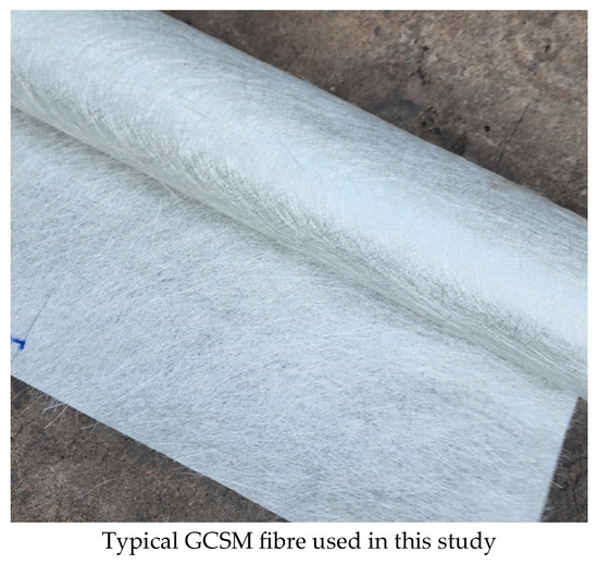
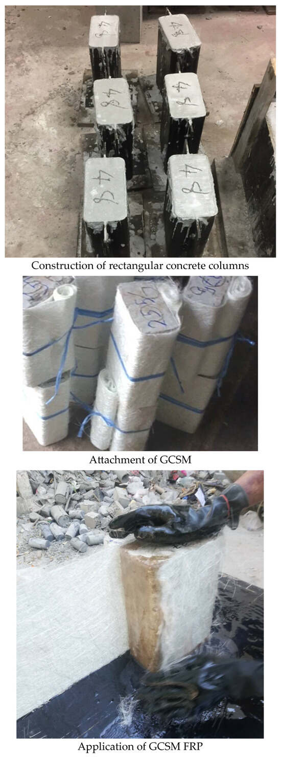
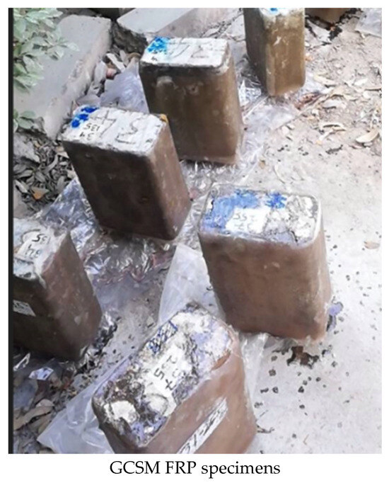
Figure 3.
Typical construction of specimens.
2.4. Test Setup and Instrumentation
All axial compression tests were conducted using a high-capacity Universal Testing Machine (UTM) with a load range of 1000 kN. The specimens were tested in a vertical orientation, and the load was applied in load control mode at a constant rate until the failure of each specimen. To ensure uniform load distribution across the specimen height, steel end plates were placed at the top and bottom of each specimen. Instrumentation for the test included two Linear Variable Displacement Transducers (LVDTs), which were mounted on opposite faces of the specimen using a dedicated frame. The LVDTs used had a measurement range of ±25 mm with an accuracy of ±0.5% of full scale and were calibrated prior to testing using a micrometre gauge. The load cell integrated within the UTM had a capacity of 1000 kN with an accuracy class of ±1%, verified by the manufacturer’s calibration certificate. These LVDTs were used to record axial deformations throughout the loading process. A calibrated load cell integrated within the UTM captured the applied load data. Both the displacement and load signals were connected to a data acquisition system, enabling continuous recording at regular intervals for subsequent analysis.
The complete setup of the testing arrangement, including the UTM, steel end platens, and mounted LVDTs, is shown in Figure 4. This setup ensured precise measurement of the axial load–displacement behaviour and facilitated detailed evaluation of the confinement effect introduced by the GCSM wrapping. The testing procedure adhered to the provisions of ASTM C39/C39M [28] for compressive strength evaluation of concrete, with appropriate modifications to suit the rectangular geometry of the specimens. These modifications involved ensuring that the specimen end surfaces were prepared to achieve perpendicularity to the loading axis, placing steel platens between the specimen and the machine platens to provide uniform load distribution, and computing compressive stresses using the actual cross-sectional area of the rectangular specimens. All other procedural aspects of ASTM C39, including specimen alignment, loading rate, and observation of failure modes, were followed without alteration. All tests were conducted at ambient laboratory conditions and were completed within an approximate duration of five minutes per specimen to maintain consistency in loading rate and boundary conditions. During each test, close observation was made to document cracking patterns, concrete crushing, and any potential delamination or rupture in the GCSM layers. The load and deformation data recorded were subsequently used to construct stress–strain curves for each specimen, enabling the assessment of confinement efficiency across different GCSM layer configurations.
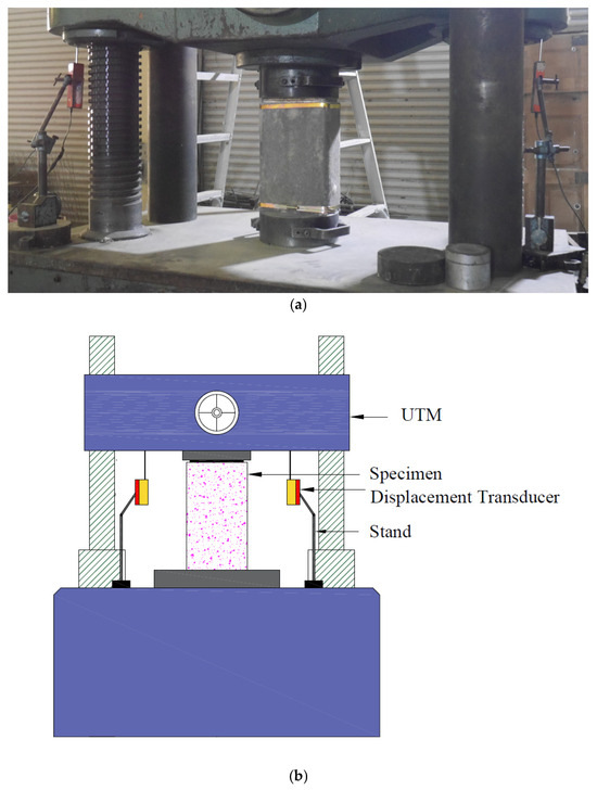
Figure 4.
Instrumentation and test setup of rectangular specimens for axial loading; (a) lab view and (b) schematic diagram.
3. Experimental Results
3.1. Failure Modes
The failure modes observed during axial compression testing of the rectangular specimens are shown in Figure 5, illustrating the distinct responses across the three concrete strength groups and various levels of GCSM confinement. Each group displayed a unique failure mechanism influenced by both the unconfined concrete strength and the number of GCSM layers applied. In Group 1 (20 MPa concrete), the unconfined control specimens exhibited typical brittle failure with sudden longitudinal splitting and crushing localized near mid-height and top corners. The cracks developed rapidly, followed by explosive spalling of concrete fragments, indicating limited ductility and energy absorption. With the application of two GCSM layers, the onset of cracking was delayed, and failure occurred with partial rupture of the confinement wrap, particularly near the specimen corners where stress concentration is highest. Increasing the confinement to three and four layers progressively suppressed crack propagation, reduced the amount of visible concrete crushing, and led to more gradual and controlled failure modes. The four-layer specimens showed minimal spalling and higher post-peak integrity, reflecting an improved confinement response in low-strength concrete.
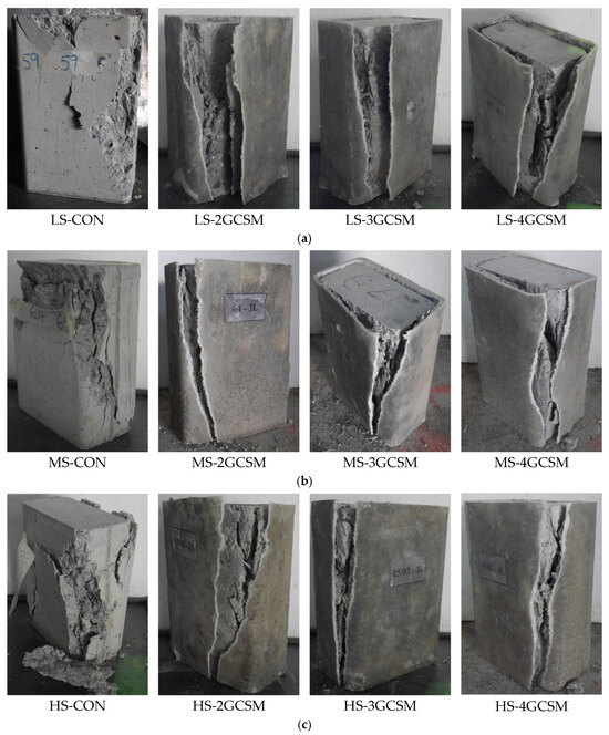
Figure 5.
Typical failure modes observed in each specimen group: (a) Group 1, LS concrete; (b) Group 2, MS concrete; (c) Group 3, HS concrete.
In Group 2 (30 MPa concrete), the control specimens again failed in a brittle manner, but with relatively better integrity compared to Group 1 due to the higher concrete matrix strength. The confined specimens showed improved structural integrity and reduced surface cracking with each additional GCSM layer. Unlike Group 1, the rupture of GCSM layers in this group predominantly occurred along the flat sides of the specimens rather than at the corners, suggesting that the corner rounding radius was effective at moderating local stress concentrations. The failure transitioned from localized crushing in two-layer specimens to distributed, ductile damage in four-layer specimens. In Group 3 (40 MPa concrete), the control specimens demonstrated high initial stiffness but failed abruptly with splitting cracks extending along the full specimen height. The confined specimens presented a bilinear failure trend. While the two-layer GCSM wraps delayed the failure, they did not prevent vertical splitting. The three- and four-layer specimens, however, showed improved crack control and ductile behaviour with reduced severity of rupture, highlighting the positive influence of confinement. Although similar in general appearance, MS-4 GCSM specimens developed wider cracks with more spalling, whereas HS-4 GCSM specimens exhibited narrower cracks and more localized crushing. The GCSM wraps contributed significantly to strain enhancement while maintaining the integrity of the concrete core, especially in higher confinement levels.
Across all groups, the GCSM confinement was effective in delaying the failure, modifying crack patterns, and increasing ductility. The number of GCSM layers played a crucial role in transforming the brittle nature of unconfined specimens into more ductile, energy-dissipating behaviour. Notably, the confinement effect was more pronounced in low-strength specimens, whereas in high-strength specimens, despite showing visible improvement, the influence was relatively subdued due to the reduced lateral dilation and internal confinement engagement of the stronger concrete matrix. No debonding was observed at the interface between the GCSM and concrete in the tested specimens, indicating good bond quality and effective confinement throughout loading. A strong bond is essential for ensuring uniform stress transfer and maximizing confinement effectiveness, as premature debonding could significantly reduce the mechanical performance. While debonding was not an issue under the applied loading conditions, it is acknowledged that under flexural or cyclic loading, debonding may occur, and the use of mechanical anchorage or additional end-anchoring techniques could be beneficial to maintain bond integrity.
The variability between the two replicate specimens in each configuration was minimal, with only slight differences in peak load and deformation capacity. These small variations did not alter the observed failure modes or the overall behavioural trends and therefore had no significant impact on the development or reliability of the proposed models or the study’s conclusions.
3.2. Stress vs. Strain Curves
The stress vs. strain behaviour of all tested specimens is presented in Figure 6, which shows the axial response of unconfined and GCSM-confined rectangular specimens. The data demonstrate that the use of GCSM as an external confinement layer positively influenced both the peak strength and deformation capacity of the specimens, although the magnitude of improvement varied with the initial concrete strength. In Group 1, the control unconfined specimen displayed a brittle response with a sharp post-peak drop, indicating limited energy absorption as illustrated in Figure 6. The application of 2 L, 3 L, and 4 L GCSM layers progressively altered the stress vs. strain response. Specifically, the 2 L specimen showed moderate enhancement in both peak stress and strain, while the 3 L specimen exhibited further improvement in strain capacity and a smoother softening branch. The 4 L specimen achieved the highest performance in terms of both strength and ductility, with a significantly flatter post-peak descent. These results confirm that in low-strength concrete, the GCSM confinement was highly effective in suppressing brittle failure and facilitating a more ductile response.
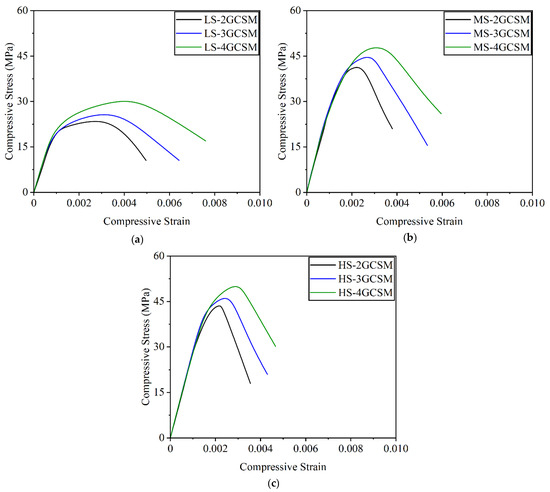
Figure 6.
Stress vs. strain behaviour of specimens confined with GCSM: (a) Group 1—Low-strength concrete, (b) Group 2—Medium-strength concrete, (c) Group 3—High-strength concrete.
Group 2 showed higher peak stress values compared to Group 1 due to the stronger concrete matrix. The unconfined specimen again failed in a brittle manner, with limited deformation prior to collapse. The 2 L and 3 L confined specimens demonstrated a progressive increase in both strength and ductility. The 4 L specimen presented the highest performance, with the most gradual slope in the post-peak region. Compared to Group 1, the effectiveness of confinement in Group 2 was still evident, though the relative gains were slightly reduced as shown in Figure 6. This is attributed to the reduced lateral expansion and stiffer matrix in medium-strength concrete, which limits the engagement of the confinement jacket. Group 3 also followed a similar trend, but with lower relative improvement due to the inherent brittleness and reduced dilation of high-strength concrete. The control specimen in this group reached a high peak stress but exhibited a steep decline post-peak. The confined specimens (2 L, 3 L, and 4 L) showed improved strain capacity and moderated post-peak softening. However, the rate of improvement from 2 L to 4 L was less pronounced than in Groups 1 and 2. This trend indicates that although GCSM confinement was still beneficial in high-strength concrete, its influence was primarily limited to enhancing ductility rather than substantially increasing strength. When comparing the three groups, the confinement effectiveness of GCSM was found to be most pronounced in low-strength concrete, followed by medium-strength, and least in high-strength concrete. The progressive flattening of the post-peak branch with increasing GCSM layers across all groups suggests a clear enhancement in energy absorption and ductility. These observations are consistent with the confinement mechanics, where lower strength concrete allows for greater lateral expansion and thus better interaction with the confinement wrap. Conversely, higher strength concrete exhibits restricted expansion and tends to crack internally, reducing the overall engagement with the confining material. Overall, the analysis of stress–strain curves confirms that GCSM wrapping effectively enhances the post-peak behaviour of concrete, particularly in weaker mixes. The results support the conclusion that both the number of confinement layers and the base concrete strength critically influence the stress–strain response and confinement efficiency.
3.3. Peak Strength and Corresponding Strain
The peak compressive strength and corresponding axial strain values obtained from the axial tests are presented in Table 3. These results offer a comparative assessment of the influence of GCSM confinement on different concrete strength categories. A consistent trend was observed across all three groups: the inclusion of GCSM wrapping significantly enhanced both the load-carrying capacity and ductility of the specimens. However, the magnitude of this enhancement varied depending on the initial strength of the concrete.

Table 3.
Peak compressive strength and strain for each specimen group.
In Group 1, the unconfined specimen showed the lowest strength and strain capacity. As the number of GCSM layers increased from 2 to 4, a progressive and substantial increase in both parameters was recorded. The maximum enhancement in Group 1 reached approximately 52% in strength and over 161% in strain, demonstrating that low-strength concrete benefits most from external confinement. Group 2 exhibited relatively higher unconfined strength, but the effect of confinement was less pronounced than in Group 1. Nonetheless, the application of GCSM still resulted in measurable gains, with peak strength and strain increasing by up to 33% and nearly 65%, respectively. This reflects the continued relevance of GCSM wrapping in medium-strength applications, particularly where ductility enhancement is a priority.
In Group 3, the unconfined specimen began with the highest base strength but exhibited the lowest relative improvement upon confinement. Even with four layers of GCSM, the peak strength gain was just above 28%, and strain improvement remained below 62%. These reduced enhancements are attributed to the inherently low lateral dilation of high-strength concrete, which limits the activation of confining pressure by external jackets. The comparatively higher percentage gain in peak stress for low-strength concrete specimens arises from their higher lateral dilation and more extensive microcrack development under load, which enables the GCSM wrap to mobilize greater confinement pressure relative to the baseline strength. In contrast, medium- and high-strength concretes, with their denser matrix and reduced lateral expansion, limit the confinement engagement, resulting in smaller proportional strength gains. Collectively, the results in Table 3 affirm that GCSM confinement is more effective in concrete with lower initial strength, yielding both higher relative strength gains and greater deformation capacity. For high-strength concrete, the improvements are present but more modest, underlining the importance of considering the base concrete properties when selecting and designing external confinement systems.
3.4. Effect of Unconfined Compressive Strength on Peak Strength and Strain
The influence of unconfined compressive strength on the effectiveness of GCSM confinement was analyzed using normalized peak strength and strain values, as presented in Table 4. The normalization was carried out relative to the unconfined strength and strain within each group, allowing for meaningful comparisons across varying strength levels and confinement ratios.

Table 4.
Influence of unconfined compressive strength and confinement ratio on normalized peak strength and strain for GCSM-confined specimens.
As observed in Table 4, Group 1 specimens showed the most pronounced gains in both normalized peak strength and strain, with LS-4GCSM reaching values of 1.525 and 2.611, respectively. The larger confinement ratios achieved in low-strength specimens (e.g., 0.10794 for LS-4GCSM) contributed to a more active engagement of the GCSM wrap, as the higher lateral dilation of weaker concrete allowed the external jacket to provide effective confining pressure. In Group 2, moderate improvements were seen, with MS-4GCSM achieving a normalized peak strength of 1.332 and a normalized strain of 1.833. These enhancements reflect a lower but still effective confinement response due to a moderately stiff concrete matrix and corresponding lateral expansion behaviour. The confinement ratios in this group ranged from 0.02936 to 0.05873, reinforcing the trend that higher confinement ratios correlate with improved normalized performance. Group 3 exhibited the lowest relative improvements, with a maximum normalized peak strength of 1.284 and normalized strain of 1.611 for HS-4GCSM. These results affirm that while confinement remains beneficial in high-strength concrete, the gains are modest due to limited lateral dilation and a more brittle failure pattern. The confinement ratios in this group were comparatively lower (0.02692–0.05384), resulting in reduced engagement of the GCSM confinement system.
The relationships between confinement ratio and normalized performance metrics are graphically illustrated in Figure 7 and Figure 8. Figure 7 shows a clear increasing trend between confinement ratio and normalized peak strength, particularly in the lower to mid-range ratios. The rate of increase tapers off at higher confinement levels, suggesting diminishing marginal benefits beyond a certain threshold. Similarly, Figure 8 plots the confinement ratio against normalized peak strain, and a strongly positive correlation is evident. The figure confirms that confinement is especially effective in enhancing ductility, with strain gains reaching more than double those of the unconfined cases at higher confinement levels.
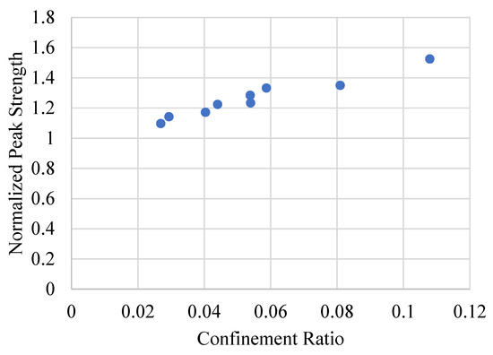
Figure 7.
Variation in normalized compressive strength with confinement ratio across specimens of different unconfined strengths.
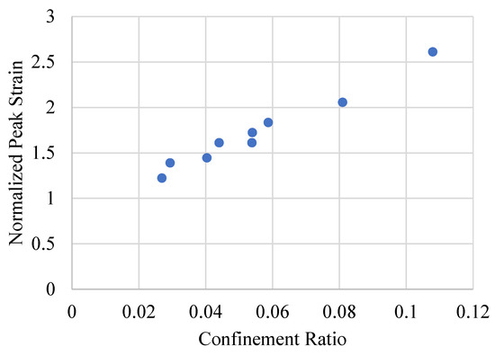
Figure 8.
Effect of confinement ratio on normalized axial strain for concrete specimens with varying initial strength.
Together, Table 4 and Figure 7 and Figure 8 highlight the critical influence of initial concrete strength on the confinement response. Confinement is most effective in low-strength concretes, where the lateral expansion allows for significant engagement of the GCSM wrap. For higher-strength concretes, the confinement mechanism is still beneficial but exhibits reduced efficiency. These findings underscore the importance of tailoring confinement strategies according to material strength, confinement ratio, and intended performance enhancements.
3.5. Post Peak Modulus
The post-peak modulus (Z), defined as the slope of the descending branch of the stress vs. strain curve after peak strength, serves as an indicator of energy dissipation and ductility degradation. The post-peak modulus (Z) is calculated as the slope of the descending portion of the stress–strain curve, immediately following peak stress, and represents the rate of strength degradation after maximum load is reached. Table 4 presents the calculated post-peak modulus values for all GCSM-confined concrete specimens, while Figure 9 graphically illustrates the relationship between confinement ratio and post-peak stiffness. As shown in Table 4, the post-peak modulus values are consistently negative, indicating a softening response of concrete after peak load in all specimens. A clear trend emerges across the three groups: with increasing confinement ratio, the absolute value of the post-peak modulus decreases, implying a more gradual decline in load-carrying capacity and improved ductility. In Group 1, the lowest strength concrete demonstrated the most significant improvements. The post-peak modulus improved from −7574.41 MPa for LS-2GCSM to −4608.32 MPa for LS-4GCSM, corresponding to a substantial reduction in brittleness. This trend reflects the strong confinement efficiency in low-strength concrete due to higher lateral expansion and better interaction with the GCSM wrap. Group 2 also exhibited a decrease in the magnitude of the post-peak modulus with increased confinement, improving from −16,588.62 MPa in MS-2GCSM to −8646.44 MPa in MS-4GCSM. Although the magnitude of change was less pronounced than in Group 1, the trend remains consistent, confirming the positive effect of additional GCSM layers. In Group 3, the trend was also observed, with the modulus shifting from −19,288.36 MPa in HS-2GCSM to −12,096.68 MPa in HS-4GCSM. However, as with other performance parameters, the confinement effect on post-peak modulus was less significant in high-strength concrete. This outcome supports the understanding that the brittleness of high-strength concrete limits the full engagement of external confinement layers in controlling post-peak behaviour.
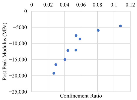
Figure 9.
Influence of confinement ratio on the post-peak modulus behaviour of GCSM-wrapped concrete specimens.
Figure 9 clearly depicts a nonlinear relationship between the confinement ratio and post-peak modulus. As the confinement ratio increases, the absolute value of the post-peak modulus decreases, indicating enhanced post-peak behaviour and delayed failure. This highlights the role of confinement in moderating the stress drop beyond peak load and improving the overall energy absorption capacity of the concrete. Overall, the results in Table 4 and Figure 9 validate that GCSM confinement not only increases peak load and strain capacity but also contributes significantly to controlling the post-peak response, especially in lower strength concretes. This further underscore the effectiveness of GCSM as a viable external confinement solution for enhancing both strength and ductility characteristics in structural applications.
3.6. Comparison of Experimental and ACI-Predicted Elastic Modulus
The elastic modulus values obtained from the experimental stress–strain curves were compared against the theoretical values predicted by ACI 318 guidelines. Table 5 summarizes this comparison, showing the unconfined compressive strength, confinement ratio, experimental elastic modulus, ACI-calculated elastic modulus, and the percentage deviation between the two. This section provides a comparison between the elastic modulus values obtained through experimental testing of GCSM-confined concrete specimens and those estimated using the empirical formula recommended by ACI 318. According to the ACI code, the static modulus of elasticity can be calculated using the expression, Where represents 28-day compressive strength of normal-weight concrete in MPa.

Table 5.
Evaluation of experimental and ACI 318-based elastic modulus values for GCSM-confined concrete specimens.
In general, the experimental elastic modulus values were found to be close to the ACI predictions, with deviations ranging between −9.72% and +5.85%. For the LS group, the deviations were mostly negative, indicating that the experimental moduli were slightly lower than the theoretical values. The largest deviation in this group was observed in LS-4GCSM with −5.64%, possibly due to microcracking and higher confinement-induced energy dissipation affecting the linear stiffness. In the MS group, deviations were mixed. While MS-2GCSM showed a positive deviation of +5.85%, the remaining specimens had relatively small negative deviations. This reflects a close alignment between the measured and predicted values, supporting the applicability of ACI 318 for medium-strength confined concrete under the studied conditions. For the HS group, all specimens showed negative deviations, increasing in magnitude with higher confinement levels. The HS-4GCSM specimen showed the maximum deviation of −9.72%. These larger deviations may be attributed to the reduced effectiveness of confinement in high-strength concrete and potential discrepancies arising from nonlinear behaviour at early load stages. Despite the observed deviations, the results indicate a reasonable agreement between experimental and ACI-predicted modulus values. This supports the use of ACI-based formulations for preliminary design and assessment of GCSM-confined concrete members, especially in low to medium strength ranges.
4. Analytical Modelling
To generalize the experimental findings and enable practical application of the results, an analytical model was developed to represent the axial compressive stress vs. strain behaviour of GCSM-confined rectangular concrete specimens. The modelling approach adopted in this study builds upon the well-established Popovics formulation [29] as shown in Equation (1) for concrete under compression, which has been widely applied to both unconfined and confined concrete systems. The primary aim of this modelling effort is to provide a simple yet accurate predictive tool for the stress vs. strain response of GCSM-confined members, calibrated against the current experimental data.
In this approach, the ascending branch of the stress vs. strain curve is represented using a nonlinear expression proposed by Popovics, as given in Equation (1). The parameter (k), which governs the curve shape, is calculated using Equation (2), incorporating the elastic modulus Ec, peak compressive strength fcc, and corresponding peak strain εcc. A schematic illustration of the idealized and observed stress vs. strain response is presented in Figure 10, showing key model parameters and the post-peak modulus Z.
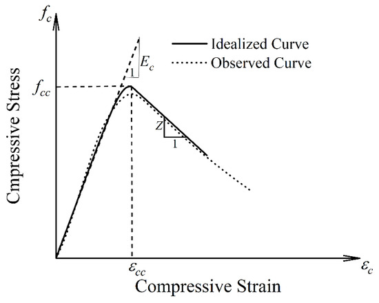
Figure 10.
Idealized stress vs. strain curve illustrating elastic modulus, peak stress, peak strain, and post-peak modulus for GCSM-confined concrete under axial compression.
4.1. Estimating the Confinement Pressure
In rectangular concrete sections, the external confining pressure provided by the GCSM jacket does not act uniformly across the cross-section due to the presence of flat faces and rounded corners. To account for this non-uniformity, an effective confinement pressure fl is calculated based on the equilibrium of lateral forces, incorporating the geometric characteristics of the section and the mechanical properties of the GCSM. The relationship between the normalized peak strength and confinement pressure is expressed as:
where fcc is the confined compressive strength, fco is the unconfined compressive strength, and k1 is a model constant obtained through regression analysis. The effective lateral confinement pressure fl generated by the GCSM layers is determined as:
where fr is the tensile strength of the GCSM material, t is the total thickness of the confinement layers, D is the equivalent diagonal dimension of the rectangular section, and ρ is the effective confinement efficiency factor representing the contribution of the flat faces and corner regions. The equivalent dimension D is calculated as:
where b and h are the width and height of the specimen cross-section, respectively. The efficiency factor ρ is given by:
where Rc is the corner radius and A is the effective confined area of the cross-section, defined as:
The confinement model is illustrated schematically in Figure 11, showing the assumed distribution of lateral confinement forces along the periphery of the section. As can be seen, the confinement is most effective along the flat faces and is moderated at the corners depending on the radius Rc, which is a critical parameter in determining the degree of confinement efficiency [30]. This formulation provides a realistic representation of the confinement mechanism in rectangular concrete sections wrapped with GCSM and forms the basis for the subsequent development of empirical models for predicting strength, strain, and post-peak response.
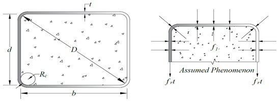
Figure 11.
Equilibrium model for GCSM-confined rectangular concrete sections.
4.2. Expression for Peak Strength
Based on regression analysis of the experimental data, an empirical model was developed to predict the normalized peak compressive strength of GCSM-confined rectangular concrete specimens as a function of the confinement pressure fl. The proposed expression is given in Table 6 and Equation (8):

Table 6.
Summary of symbols used in Popovics-based equations.
The goodness of fit of the proposed model is excellent, with an R2 value of 0.99, indicating that the model accurately captures the relationship between confinement pressure and peak strength. The comparison between the predicted and experimental values is shown in Figure 12a. The ANOVA results are shown in Figure 13a.
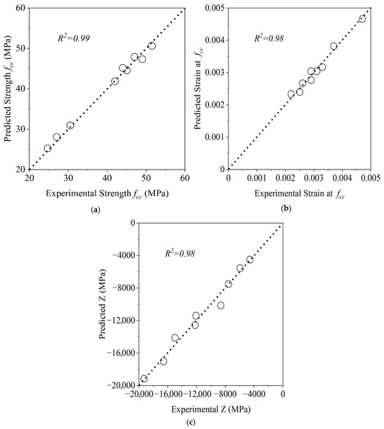
Figure 12.
Regression analysis results: (a) predicted vs. experimental peak strength fcc; (b) predicted vs. experimental peak strain εcc; (c) predicted vs. experimental post-peak modulus Z.
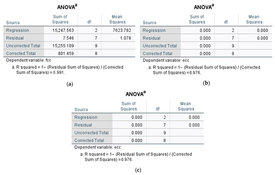
Figure 13.
ANOVA results: (a) model for fcc; (b) model for εcc; and (c) model for Z.
4.3. Expression for Strain at Peak Strength
Similarly, a model was established to predict the peak axial strain εcc as a function of confinement pressure. The following expression was obtained from the regression analysis:
4.4. Expression for Post-Peak Modulus (Z)
To characterize the post-peak response of the confined specimens, an empirical equation was developed to predict the post-peak modulus Z as a function of confinement pressure. The proposed model is given by:
4.5. Comparison of Predicted and Experimental Response
To validate the accuracy of the proposed analytical models, the predicted stress vs. strain curves were compared with the experimentally measured responses for GCSM-confined rectangular concrete specimens. The comparisons for each concrete strength group—LS, MS, and HS—are presented in Figure 14. As shown in Figure 14, the predicted curves demonstrate excellent agreement with the experimental data across all three strength levels and confinement configurations. For LS group, the models accurately capture both the ascending branch and the peak region of the stress vs. strain response. The post-peak behaviour is also well represented, with only minor deviations observed at larger strains, particularly in the most confined specimens (LS-4GCSM), where greater variability is expected due to the more ductile nature of the response.
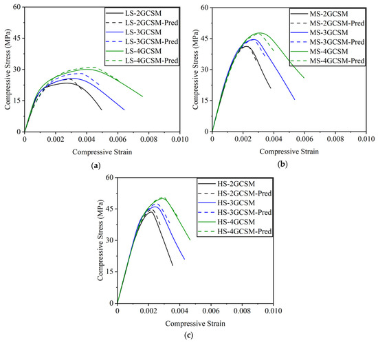
Figure 14.
Comparison of predicted and experimental axial stress vs. strain curves for GCSM-confined rectangular concrete specimens: (a) LS group; (b) MS group; (c) HS group.
In the MS group, the agreement between predicted and experimental curves remains strong. Both the stiffness of the ascending branch and the peak stress are effectively modelled, while the post-peak slope is consistent with the observed trends. The slight divergence in the softening region of highly confined specimens can be attributed to the complex interaction between the confinement jacket and the concrete core during large inelastic deformations [31]. For the HS group, the models continue to perform well, though the accuracy of the post-peak region shows a slight reduction compared to the lower-strength groups. This behaviour is consistent with the more brittle nature of high-strength concrete, which limits the degree of lateral expansion and confinement engagement. Despite this, the proposed models still provide reliable predictions of the overall stress vs. strain behaviour, including peak strength, peak strain, and initial stiffness.
The absence of direct hoop strain measurement and adhesion data limits the depth of confinement mechanism interpretation; however, this limitation aligns with other initial studies on low-cost confinement systems, where axial performance is emphasized before extending to multi-parameter testing [19,24]. Overall, the comparisons in Figure 14 confirm that the developed analytical models are capable of accurately representing the axial compressive response of GCSM-confined rectangular concrete specimens across a broad range of concrete strengths and confinement levels. The models are therefore suitable for practical design and assessment of such confined systems.
The proposed analytical models were developed based on the tested configurations and exhibited excellent agreement with the experimental data. While the underlying formulation is grounded in fundamental confinement mechanics, their direct applicability beyond the tested configurations should be approached with caution. The models are expected to provide reasonable predictions for similar materials, geometries, and confinement schemes; however, for significantly different parameters (e.g., concrete strength, GCSM properties, or loading conditions), calibration or validation with additional experimental data is recommended to ensure accuracy. At present, there remain no other existing dataset of GCSM-confined rectangular specimens. Therefore, independent verification of the proposed models could not be achieved. However, future works should assess the applicability of proposed models.
5. Conclusions
This experimental study evaluated the confinement effects of low-cost GCSM sheets on rectangular concrete specimens of varying strengths. The key conclusions drawn from the results are as follows:
- Significant enhancement in strength and ductility was observed with the application of GCSM, particularly in low-strength concrete. An up to 34% gain in peak strength and an over 60% improvement in strain were achieved in the most confined low-strength specimens.
- The effectiveness of GCSM confinement decreases with increasing unconfined concrete strength. High-strength specimens showed modest gains in normalized performance due to limited lateral expansion.
- Post-peak behaviour improved with higher confinement ratios, as indicated by a reduction in the absolute value of the post-peak modulus. This demonstrates enhanced energy dissipation and delay in brittle failure.
- Normalized peak strength and strain correlated positively with the confinement ratio, confirming its reliability as a confinement performance indicator across all strength groups.
- Elastic modulus values estimated using ACI 318 closely matched the experimental values, especially for low- and medium-strength specimens, supporting the validity of ACI-based preliminary assessments for GCSM-confined concrete.
- Analytical models were developed for predicting peak strength, peak strain, and post-peak modulus of GCSM-confined rectangular specimens. The models showed excellent predictive accuracy, with R2 values exceeding 0.98, and were validated against experimental stress vs. strain curves. Overall, the study affirms the potential of GCSM as a practical and economical retrofitting material for structural applications. Its ease of application, cost-effectiveness, and favourable mechanical performance make it a promising solution for strengthening existing infrastructure, particularly in resource-constrained environments.
The present study is limited to the specific range of concrete strength, specimen geometry, and GCSM confinement configuration investigated. The specimen size was restricted to laboratory scale, and scale effects on larger structural members were not considered. The performance under different loading types, such as flexure, cyclic, or fatigue loading, was not evaluated and may influence the confinement effectiveness. Additionally, environmental durability aspects, such as long-term bond performance under varying temperature and moisture conditions, were not addressed. Future research could explore hoop strain monitoring, lateral expansion measurements, and adhesion verification tests, as well as the optimization of anchorage systems to prevent debonding under complex loading and extend the proposed analytical models to a broader range of material properties and structural applications.
Author Contributions
Methodology, P.C. and S.S.; Formal analysis, G.S.-I.; Investigation, P.C., B.C., Q.H. and A.A.; Resources, S.S.; Data curation, G.S.-I. and A.A.; Writing—original draft, B.C.; Project administration, Q.H. All authors have read and agreed to the published version of the manuscript.
Funding
Research Funding Received from University of Phayao, Phayao, Thailand (Fundamental fund (FF68 UOE) 5040/2567).
Data Availability Statement
Data are contained within the article.
Acknowledgments
The authors of this research work are very grateful to the University of Phayao, Phayao, Thailand, for providing a research grant (Fundamental fund (FF68 UOE) 5040/2567) to carry out the research work. Thanks are also extended to AIT, Thailand, for supporting test facilities.
Conflicts of Interest
The authors declare no conflicts of interest.
References
- Teng, J.G.; Yu, T.; Fernando, D. Strengthening of steel structures with fiber-reinforced polymer composites. J. Constr. Steel Res. 2012, 78, 131–143. [Google Scholar] [CrossRef]
- Yooprasertchai, E.; Saingam, P.; Hussain, Q.; Khan, K.; Ejaz, A.; Suparp, S. Development of stress-strain models for glass fiber reinforced polymer composites confined sustainable concrete made with natural and recycled aggregates. Constr. Build. Mater. 2024, 416, 135097. [Google Scholar] [CrossRef]
- Sengun, K.; Arslan, G. Performance of RC Beams Strengthened in Flexure and Shear with CFRP and GFRP. Iran. J. Sci. Technol. Trans. Civ. Eng. 2024, 48, 117–130. [Google Scholar] [CrossRef]
- Mohanraj, R.; Senthilkumar, S.; Padmapoorani, P. Mechanical Properties of Rc Beams with Afrp Sheets Under A Sustained Load. Mater. Technol. 2022, 56, 365–372. [Google Scholar] [CrossRef]
- Lee, H.K.; Cheong, S.H.; Ha, S.K.; Lee, C.G. Behavior and performance of RC T-section deep beams externally strengthened in shear with CFRP sheets. Compos. Struct. 2011, 93, 911–922. [Google Scholar] [CrossRef]
- Khalifa, A.; Nanni, C. Improving shear capacity of existing RC T-section beams using CFRP composites. Cem. Concr. Compos. 2000, 22, 165–174. [Google Scholar] [CrossRef]
- Joyklad, P.; Saingam, P.; Ali, N.; Ejaz, A.; Hussain, Q.; Khan, K.; Chaiyasarn, K. Low-cost fiber chopped strand mat composites for compressive stress and strain enhancement of concrete made with brick waste aggregates. Polymers 2022, 14, 4714. [Google Scholar] [CrossRef]
- Thansirichaisree, P.; Mohamad, H.; Zhou, M.; Ejaz, A.; Saingam, P.; Hussain, Q.; Suparp, S. Behavior of shallow concrete beams strengthened using low-cost GCSM and mechanical anchors. AIMS Mater. Sci. 2024, 11, 858–881. [Google Scholar] [CrossRef]
- Lam, A.P.; Lalin, Q.H. Shear strengthening of RC deep beams using glass chopped strand mat (GCSM). Eng. J. Res. Dev. 2014, 25, 25–33. [Google Scholar] [CrossRef]
- Lam, A.Q.; Khan, A. Pimanmas, A. Shear strengthening of RC deep beams using glass chopped strand mat (GCSM) composite. Case Stud. Constr. Mater. 2022, 16, e01018. [Google Scholar] [CrossRef]
- Alhilli, H.H.; Al-Farttoosi, M.H. Shear performance of reinforced concrete t beams strengthened by carbon fiber-reinforced polymer bars. Civ. Eng. J. 2023, 9, 10. [Google Scholar] [CrossRef]
- Fathalla, E.; Mihaylov, B. Shear behaviour of deep beams strengthened with high-strength fiber reinforced concrete jackets. Eng. Struct. 2025, 325, 119404. [Google Scholar] [CrossRef]
- Chole, A.; Tembhurne, A.; Bawanthade, H.; Bhadade, H.; Ali Khan, S. Kumar Shaw, Strengthening of reinforced concrete beams by using FRPs-An overview. Mater. Today Proc. 2023. [Google Scholar] [CrossRef]
- Zhou, H.; Fernando, D.; Nguyen, V.T.; Dai, J.-G. The bond behaviour of CFRP-to-concrete bonded joints under fatigue cyclic loading: An experimental study. Constr. Build. Mater. 2021, 273, 121674. [Google Scholar] [CrossRef]
- Zhang, Z.; Hsu, C.-T.T.; Moren, J. Shear Strengthening of Reinforced Concrete Deep Beams Using Carbon Fiber Reinforced Polymer Laminates. J. Compos. Constr. 2004, 8, 403–414. [Google Scholar] [CrossRef]
- Chen, G.M.; Teng, J.G.; Chen, J.F. Shear strength model for FRP-strengthened RC beams with adverse FRP-steel interaction, Ascelibrary. J. Compos. Constr. 2013, 17, 50–66. [Google Scholar] [CrossRef]
- Galal, K.; Arafa, A.; Ghobarah, A. Retrofit of RC square short columns. Eng. Struct. 2005, 27, 801–813. [Google Scholar] [CrossRef]
- Bank, L.C.; Arora, D. Analysis of RC beams strengthened with mechanically fastened FRP (MF-FRP) strips. Compos. Struct. 2007, 79, 180–191. [Google Scholar] [CrossRef]
- Al-Tameemi, H.; Akın, E. Improving the efficiency of FRP-Confined square concrete column by rounding the sharp edges and circularizing the flat sides. Structures 2022, 45, 1762–1773. [Google Scholar] [CrossRef]
- Wang, D.; Wang, Z.; Smith, S.; Yu, T. Size effect on axial stress-strain behavior of CFRP-confined square concrete columns. Constr. Build. Mater. 2016, 118, 116–126. [Google Scholar] [CrossRef]
- Rodsin, K.; Hussain, Q.; Parichatprecha, R. Monotonic and cyclic axial compressive responses of concrete specimens externally confined with different types of FRP composites: Experimental and analytical investigations. Phys. Scr. 2023, 98, 105932. [Google Scholar] [CrossRef]
- Cui, E.; Jiang, S.; Wang, J.; Zeng, X. Bond behavior of CFRP-concrete bonding interface considering degradation of epoxy primer under wet-dry cycles. Constr. Build. Mater. 2021, 292, 123286. [Google Scholar] [CrossRef]
- Wang, Z.; Li, Z.; Yang, J.-Q.; Huang, F.; Feng, P. Axial compressive and seismic performance of GFRP wrapped square RC columns with different scales. J. Build. Eng. 2022, 62, 105342. [Google Scholar] [CrossRef]
- de Diego, A.; Martínez, S.; Castro, V.J.; Echevarría, L.; Barroso, F.J.; Gutiérrez, J.P. Experimental investigation on the compressive behaviour of FRP-confined rectangular concrete columns. Arch. Civ. Mech. Eng. 2022, 22, 131. [Google Scholar] [CrossRef]
- Liao, J.; Zeng, J.-J.; Gong, Q.-M.; Quach, W.-M.; Gao, W.-Y.; Zhang, L. Design-oriented stress-strain model for FRP-confined ultra-high performance concrete (UHPC). Constr. Build. Mater. 2022, 318, 126200. [Google Scholar] [CrossRef]
- ASTM C 33/C 33–08 i (2009); International, Standard Specification for Concrete Aggregates. ASTM: West Conshohocken, PA, USA, 2009.
- ASTM D3039/D3039M-08; Standard Test Method for Tensile Properties of Polymer Matrix Composite Materials. ASTM International: West Conshohocken, PA, USA, 2008. [CrossRef]
- ASTM C 39 04 (2001) 1–5; Standard Test Method for Compressive Strength of Cylindrical Concrete Specimens. ASTM International: West Conshohocken, PA, USA, 2014.
- Popovics, S. A numerical approach to the complete stress-strain curve of concrete. Cem. Concr. Res. 1973, 3, 583–599. [Google Scholar] [CrossRef]
- Mostofinejad, D.; Moshiri, N.; Mortazavi, N. Effect of corner radius and aspect ratio on compressive behavior of rectangular concrete columns confined with CFRP. Mater. Struct. Constr. 2015, 48, 107–122. [Google Scholar] [CrossRef]
- Minafò, G.; Papia, M. Concrete softening effects on the axial capacity of RC jacketed circular columns. Eng. Struct. 2016, 128, 215–224. [Google Scholar] [CrossRef]
Disclaimer/Publisher’s Note: The statements, opinions and data contained in all publications are solely those of the individual author(s) and contributor(s) and not of MDPI and/or the editor(s). MDPI and/or the editor(s) disclaim responsibility for any injury to people or property resulting from any ideas, methods, instructions or products referred to in the content. |
© 2025 by the authors. Licensee MDPI, Basel, Switzerland. This article is an open access article distributed under the terms and conditions of the Creative Commons Attribution (CC BY) license (https://creativecommons.org/licenses/by/4.0/).