Article

Buckling Characteristics of Bio-Inspired Helicoidal Laminated Composite Spherical Shells Under External Normal and Torsional Loads Subjected to Elastic Support

1
Department of Mechanical Engineering, Islamic Azad University, North Tehran Branch, Tehran 16511-53311, Iran
2
Faculty of Mechanical Engineering, K.N. Toosi University of Technology, Tehran 19991-43344, Iran
3
Advanced Research and Development Center, LIPS Research Foundation, European International University, 75018 Paris, France
*
Authors to whom correspondence should be addressed.
Buildings 2025, 15(17), 3165; https://doi.org/10.3390/buildings15173165
Submission received: 2 August 2025 / Revised: 28 August 2025 / Accepted: 31 August 2025 / Published: 3 September 2025
(This article belongs to the Special Issue Computational Mechanics Analysis of Composite Structures)

Abstract

Spherical shells exhibit superior strength-to-geometry efficiency, making them ideal for industrial applications such as fluid storage tanks, architectural domes, naval vehicles, nuclear containment systems, and aeronautical and aerospace components. Given their critical role, careful attention to the design parameters and engineering constraints is essential. The present paper investigates the buckling responses of bio-inspired helicoidal laminated composite spherical shells under normal and torsional loading, including the effects of a Winkler elastic medium. The pre-buckling equilibrium equations are derived using linear three-dimensional (3D) elasticity theory and the principle of virtual work, solved via the classical finite element method (FEM). The buckling load is computed using a nonlinear Green strain formulation and a generalized geometric stiffness approach. The shell material employed in this study is a T300/5208 graphite/epoxy carbon fiber-reinforced polymer (CFRP) composite. Multiple helicoidal stacking sequences—linear, Fibonacci, recursive, exponential, and semicircular—are analyzed and benchmarked against traditional unidirectional, cross-ply, and quasi-isotropic layups. Parametric studies assess the effects of the normal/torsional loads, lamination schemes, ply counts, polar angles, shell thickness, elastic support, and boundary constraints on the buckling performance. The results indicate that quasi-isotropic (QI) laminate configurations exhibit superior buckling resistance compared to all the other layup arrangements, whereas unidirectional (UD) and cross-ply (CP) laminates show the least structural efficiency under normal- and torsional-loading conditions, respectively. Furthermore, this study underscores the efficacy of bio-inspired helicoidal stacking sequences in improving the mechanical performance of thin-walled composite spherical shells, exhibiting significant advantages over conventional laminate configurations. These benefits make helicoidal architectures particularly well-suited for weight-critical, high-performance applications in aerospace, marine, and biomedical engineering, where structural efficiency, damage tolerance, and reliability are paramount.

1. Introduction

Natural structures exemplify optimal structural efficiency, inspiring the development of advanced composite materials that combine lightweight properties with outstanding mechanical performance. By emulating the hierarchical and helicoidal architectures observed in biological systems, bio-inspired composites are transforming structural engineering paradigms. These materials demonstrate superior strength-to-weight ratios, enhanced damage tolerance, and remarkable mechanical resilience—attributes particularly valuable for aerospace, marine, and automotive applications. In contemporary engineering, where the demand for lightweight yet high-strength materials continues to grow, bio-inspired helicoidal structures have garnered significant research attention due to their exceptional mechanical properties and potential applications in aerospace and marine engineering.
Through careful examination of natural biological systems, researchers have identified remarkable structural characteristics—including high stiffness, exceptional strength, and superior fracture toughness—in various organisms. Examples range from crustacean exoskeletons [1] and snail shells [2] to diving bell spider silk [3] and sea urchin skeletal microstructures [4]. Further instances include helical collagen arrangements in mammalian bone tissue [5,6], helical skeletal ridges in deep-sea sponges (Hexactinellida) [7], and the helicoidally reinforced dactyl club of stomatopods [8]. The most prominent example is the Bouligand structure found in the exoskeletons of crustaceans, such as lobsters and the mantis shrimp. In these biological composites, layers of fibrous chitin are arranged with a gradual, helicoidal rotation, a design that confers exceptional fracture toughness and resistance to impact and compression by forcing cracks to propagate tortuously [1,8]. Similarly, the cell walls of many plants exhibit a helicoidal arrangement of cellulose microfibrils, providing optimal resistance to torsional and bending stresses [9]. The sophisticated material architectures observed across diverse biological systems, which consistently yield remarkable mechanical properties, serve as natural paradigms for bio-inspired design. This work translates these evolutionarily proven advantages—specifically, enhanced stability and damage tolerance—to the macroscopic scale by developing helicoidal composite laminates for engineered spherical shell structures subjected to critical buckling loads.
The concept of Bouligand structures, characterized by helicoidally stacked unidirectional fiber plies with incremental angular rotation between adjacent layers, was first identified in natural systems during the 1960s [10] and 1970s [11]. These biologically inspired laminated architectures exhibit a distinctive helical arrangement resembling a circular staircase or helical spring morphology. The relative rotation angle between successive plies represents a critical design parameter that significantly influences the mechanical behavior of helicoidal laminates. By emulating the spiral fiber configurations observed in biological composites [12], helicoidal laminates demonstrate superior structural resilience and enhanced mechanical performance. This biomimetic approach facilitates the development of lightweight yet durable materials for advanced engineering applications [13], offering optimized characteristics including improved stiffness-to-weight ratios, reduced densities, exceptional strength properties, superior energy absorption capacities, and enhanced fracture toughness [14]. The mechanical properties of these laminates, including their strength, toughness, and hardness, can be precisely tailored through the strategic modification of ply parameters such as the layer count, thickness, and angular orientation. Consequently, researchers have systematically investigated various helicoidal stacking sequences to fully exploit their engineering potential.
Fiber-reinforced composites—materials composed of high-strength fibers embedded in a binding matrix—offer exceptional strength, stiffness, and durability, making them ideal for aerospace, automotive, marine, and civil engineering applications. Their ability to enhance structural performance has led to their widespread use in strengthening and retrofitting structural components [15]. Recently, bio-inspired helicoidal composite structures have emerged as a superior alternative to conventional designs, offering enhanced damage resistance and impact energy absorption. In structural engineering, such complex geometries are often modeled as assemblies of simplified elements—including plates, beams, and curved shells (e.g., cylindrical, spherical, conical)—to facilitate design and analysis while leveraging the superior mechanical properties of composites [16]. As a result, substantial research has been directed toward analyzing the mechanical performance of these advanced materials, with extensive investigations focusing on their static behavior, dynamic response, impact resilience, buckling and post-buckling stability, and vibrational characteristics.
Bio-inspired helicoidal configurations have been extensively studied for their influence on the mechanical properties of plate structures. Saurabh et al. [17] demonstrated that the stacking sequence of helicoidal laminates significantly affects nonlinear natural frequencies and static responses. Similarly, Mohamed et al. [18] employed first-order shear deformation theory (FSDT) and the differential quadrature method (DQM) to analyze static, vibrational, and stability characteristics, identifying optimal fiber orientations for enhanced structural performance. Dynamic responses under explosive loads were examined by Do et al. [19] using isogeometric analysis (IGA) and higher-order shear deformation theory (HSDT), revealing superior vibration damping and energy absorption in helicoidal arrangements. Impact resistance was further explored by Baakeel et al. [20], who showed that helicoidal curved plates reduce deflection and impact force, while Garg et al. [21] assessed the damage tolerance in perforated plates under bird-strike scenarios using a smoothed particle hydrodynamics (SPH)–finite element method (FEM) model in ABAQUS. Melaibari et al. [22] introduced artificial delaminations to mimic core–shell microstructures, achieving remarkable improvements in ductility (208% strain increase) and energy absorption (288.1%) compared to conventional laminates. For buckling and vibration analysis, Doan et al. [23] applied a meshfree Moving Kriging (MK) approach, emphasizing its effectiveness for complex geometries. Wang et al. [24] experimentally validated the high-speed impact tolerance of helix laminated composites, noting a superior performance with brittle fibers but reduced efficacy with tough aramid fibers. Garg et al. [25] performed an FEA and highlighted the exceptional buckling resistance and unique diagonal failure symmetry of bio-inspired helicoidal plates, while Lu et al. [26] optimized hybrid helicoidal laminates by combining linear (L), recursive (R), Fibonacci (F), and exponential (E) stacking sequences, yielding a 35–50% increase in the buckling resistance and a 40–60% superior thermal performance to that of traditional configurations.
While bio-inspired helicoidal laminates have been widely studied for rectangular plates, their mechanical behavior in annular-plate configurations remains less explored. Garg et al. [27] employed isogeometric analysis (IGA) and machine learning-based stiffness modeling to investigate free vibrations in sinusoidal corrugated annular plates, demonstrating that helicoidal layups enhance structural performance through synergistic interactions between the layer orientation, cutout location, and boundary conditions. In contrast, Bayat et al. [28] utilized FSDT to analyze helicoidally laminated annular sector plates and compared them with traditional layups, revealing that conventional unidirectional (UD) laminates outperform helicoidal configurations in their free-vibration and static-deflection responses. Further expanding this work, Garg et al. [29] applied IGA and refined plate theory to evaluate free vibrations in both square and annular helicoidal plates with circular cutouts, providing additional insights into the dynamic behavior of these geometrically complex structures.
Bio-inspired hierarchical architectures have demonstrated substantial enhancements in the mechanical performance of beam-type laminated composites. Almitani et al. [30] derived exact solutions for the nonlinear bending and buckling of helicoidal composite beams using Laplace transforms, highlighting the pronounced influence of helicoidal layups on the nonlinear structural behavior. Mohamed et al. [31] advanced this understanding by developing a differential integral quadrature method (DIQM)-based model to analyze imperfect helicoidal beams, showing that helicoidal recursive (HR) and helicoidal exponential (HE) configurations markedly improve critical buckling loads, especially under high imperfection amplitudes. Further insights were provided by Pham et al. [32], who employed multi-theory analysis (classical to quasi-3D beam theories) to evaluate helicoidal curved beams. Their results indicated that HR and HE designs exhibited minimal deflection and superior stiffness, whereas helicoidal semicircular (HS) beams with larger fiber angles experienced greater deformations. Notably, increasing the fiber angles amplified normal stress while reducing shear stress, creating unique interfacial coupling effects absent in straight beams. Beyond mechanical loading, Amara et al. [33] investigated the thermo-hygroscopic effects on bio-inspired helicoidally laminated composite plates used to rehabilitate damaged RC beams, identifying the laminate/adhesive stiffness, plate thickness, and helicoidal layup as critical factors controlling the interfacial shear and normal stresses. Complementing these studies, Yang et al. [34] numerically validated the dynamic performance of Bouligand-type helicoidal structures, revealing their exceptional ability to attenuate stress waves and mitigate transmitted forces under impact and blast loading.
Recent studies have advanced the understanding of bio-inspired helicoid stacking sequences in curved shell structures, revealing their superior mechanical performance compared to conventional laminates. Garg et al. [35] developed a machine learning-enhanced framework combining IGA and HSDT to analyze Miura-folded helicoidal shells, demonstrating that larger inter-ply angles enhance natural frequencies and dynamic performance. Complementing this, Khotjanta et al. [36] established an analytical model showing that helicoidal architectures effectively mitigate interlaminar stresses through optimized fiber angles. Further investigations by Garg et al. [37] employed multi-output Support Vector Machine (SVM) modeling to reveal that while cross-ply and quasi-isotropic laminates perform optimally in intact shells, Fibonacci and semicircular layups exhibit superior buckling resistance in shells with cutouts, with the HS layup, particularly, showing peak load capacity for circular holes. Kalhori et al. [38] extended this work through 3D elasticity theory and finite element analysis, demonstrating the FH pattern’s dominance in axial buckling and the HS pattern’s excellence in torsional buckling, both outperforming traditional laminates, while the HR (β = 1) pattern consistently underperformed. Additionally, Garg et al. [39] examined the free vibrations in helicoidal shell panels under thermal conditions using SVM modeling with parabolic shear deformation theory. Finally, Thu et al. [40] investigated blast-loaded doubly curved helicoidal shells via enhanced FSDT and IGA, revealing that the layer count and spiral configuration critically influence the stiffness, while the curvature radius induces asymmetric normal-stress distribution through the thickness.
Among the various shell geometries, spherical shells demonstrate superior strength-to-weight characteristics while maintaining geometric simplicity, outperforming even cylindrical configurations in their structural efficiency. Spherical caps are widely utilized in engineering and scientific applications due to their exceptional load-bearing and strength-to-geometry efficiency, geometric symmetry, and stress distribution characteristics. In mechanical and civil engineering, they serve as optimal structures for pressure vessels, including LPG tanks and submarine hulls, where uniform stress dissipation under external loads is essential [41]. Architectural designs, such as geodesic domes, employ spherical caps for both structural resilience and visual appeal, while aerospace systems integrate them into satellite housings and telescope mirrors to ensure precision and durability. Their acoustic properties enhance sound reflection in auditoriums and directional microphones, and their biomechanical compatibility makes them suitable for artificial joints and controlled-release drug capsules. At smaller scales, spherical shells model fluid droplet dynamics in inkjet printing and function as nanocatalysts or energy storage mediums. Furthermore, their impact-resistant and aerodynamic qualities benefit sports equipment like helmets and golf balls, and their mechanical stability supports MEMS-based sensors and actuators. From macroscopic infrastructure to microscopic biomedical devices, the versatility of spherical shells underscores their significance in advancing both theoretical research and practical engineering solutions. The mechanical behavior of spherical shells has been extensively studied to address their diverse aspects. Zhang et al. [42] demonstrated that spherical caps fail predictably via local dimpling, even with imperfections, underscoring their reliability in deep-sea environments. Nonlinear dynamics further complicate their response, as Iarriccio et al. [43] revealed that shallow spherical caps under harmonic pressure exhibit chaotic vibrations, with abrupt transitions between dynamic states. These findings offer critical insights for pressure vessel design. Geometric and material considerations also play pivotal roles—Malek et al. [44] showed that quadrilateral grid-shells outperform triangular configurations in shallow caps due to their superior imperfection tolerance. Advances in functionally graded materials (FGMs) have expanded their utility, as demonstrated by Shen et al. [45], who analyzed graphene-reinforced porous spherical caps on elastic foundations, and Minh et al. [46], who investigated sandwich FG caps with porous cores using nonlinear FSDT to resolve vibration responses. Yadav et al. [47] highlighted curvature-dependent vibrational behavior, with near-complete shells exhibiting frequencies magnitudes higher than those of caps under strain gradient theory. Complementing these, Kalleli et al. [48] developed an FSDT-based solid-shell element for the 3D buckling analysis of FG porous caps, eliminating shear correction factors. Collectively, these studies underscore the interplay of geometry, material innovation, and dynamic loading in optimizing spherical shells for multidisciplinary applications.
A comprehensive review of the literature on bio-inspired helicoidal laminated composites reveals a notable gap: the buckling behavior of spherical shells incorporating such hierarchical architectures has not yet been investigated, despite their geometric and functional relevance in a wide range of engineering applications, including aerospace, marine, energy, and biomedical systems. Specifically, to the best of the authors’ knowledge, no prior study has examined the stability of spherical shells under torsional loading, irrespective of material configuration. This gap is particularly significant given the prevalence of torsional effects in practical scenarios. For instance, in biomechanical systems such as artificial joints and orthopedic implants, torsional moments naturally arise due to the rotational dynamics of human motion. The hemispherical geometry in such applications is not only anatomically compatible but also structurally optimal, enabling efficient stress distribution under complex load paths. Similarly, in high-performance aerospace systems—such as fighter aircrafts—the structural components experience substantial torsional loading during high-G maneuvers, rapid directional changes, and aerodynamic turbulence. Components like radomes and pressure shells must resist these twisting forces without compromising functionality. In rotating machinery, such as wind turbines, the caps of large rotary shafts encounter considerable torsional moments due to torque transmission and dynamic imbalance. Gearbox housings in high-speed systems are also subjected to torsional stresses induced by internal viscous flows. Moreover, in equipment like centrifuges and undersea devices, the interaction between rotating fluids and curved shell surfaces imposes non-uniform shear and pressure fields, further emphasizing the need for rigorous torsional-buckling analysis.
This study addresses a critical knowledge gap by pioneering the investigation into the buckling responses of bio-inspired helicoidally laminated spherical shells. These shells were subjected to uniform external pressure and torsional loads while being modeled on an elastic (Winkler-type) foundation. In contrast to most of the existing research, which relies on simplified shell theories with von Kármán-type kinematics, the present analysis employs a comprehensive 3D linear elasticity framework. The pre-buckling equilibrium equations are rigorously derived using the principle of virtual work. Subsequently, the critical buckling loads are computed via a robust formulation. This formulation integrates nonlinear Green–Lagrange strain tensors with a generalized geometric stiffness matrix, thereby enabling a kinematically consistent and accurate prediction of instability. A principal advantage of this methodology is its ability to capture through-thickness deformation effects, which are typically neglected in conventional shell models.
The novelty of this research is multifaceted and represents a significant expansion of the existing literature on bio-inspired composites. First, it presents the first known analysis of buckling in bio-inspired helicoidal laminated partial spherical shells. Second, it pioneers the investigation of torsional buckling for this specific geometry. Third, it incorporates the effect of an elastic Winkler foundation, a crucial factor for practical applications that has not been previously studied in this context. Finally, this study employs a rigorous 3D elasticity approach with a full Green–Lagrange strain formulation, offering superior accuracy for capturing the complex mechanics of thick, multi-layered laminates. This holistic approach provides new, foundational insights into the stability of advanced biomimetic structures under complex realistic conditions.
This study focuses on partial spherical shells fabricated from T300/5208 graphite/epoxy carbon fiber-reinforced polymer (CFRP) laminates, configured in helicoidal stacking sequences. Several hierarchical layup strategies—linear, Fibonacci, recursive, exponential, and semicircular—are analyzed and compared against conventional unidirectional, cross-ply, and quasi-isotropic arrangements. The influence of key parameters such as the loading type, lamination pattern, ply count, polar angle, shell thickness, foundation stiffness, and boundary conditions is systematically investigated.
In structural mechanics, boundary conditions are rarely idealized but are instead governed by elastic interactions with supporting media. This study, therefore, employs an elastic foundation model to accurately capture this pervasive compliance. Specifically, the classical Winkler foundation hypothesis is adopted, a well-established approach that idealizes the supporting medium as a bed of linear springs, providing resistance proportional to the local displacement. The profound relevance of this model is underscored by its vast array of engineering applications, which extend far beyond traditional geotechnical contexts. These applications include, but are not limited to, structures resting on soil strata or compacted gravel; pipelines buried in backfill; storage tanks on elastic pads; aerospace components mounted on vibration-isolating elastomers; naval hulls interacting with water; composite sandwich panels with polymeric, metallic, or fiber-reinforced foam cores; civil infrastructure elements encased in concrete; and electronic components mounted on compliant substrates. By moving beyond the limitations of idealized clamped and free edges, this approach is indispensable for predicting realistic structural responses, achieving accurate stress and strain distributions, enhancing stability, and ultimately bridging the critical gap between theoretical analysis and practical structural performance. It is noteworthy that the current model assumes an idealized, defect-free laminate geometry, yielding upper-bound structural performance predictions. In reality, manufacturing processes strongly influence actual behavior, with manual methods like hand lay-up susceptible to fiber misalignment and voids that reduce the stiffness and buckling capacity. In contrast, automated techniques provide precise control over the fiber orientation, enabling the more accurate realization of complex helicoidal architectures and the closer attainment of their theoretical performance benefits.

2. Problem Definition

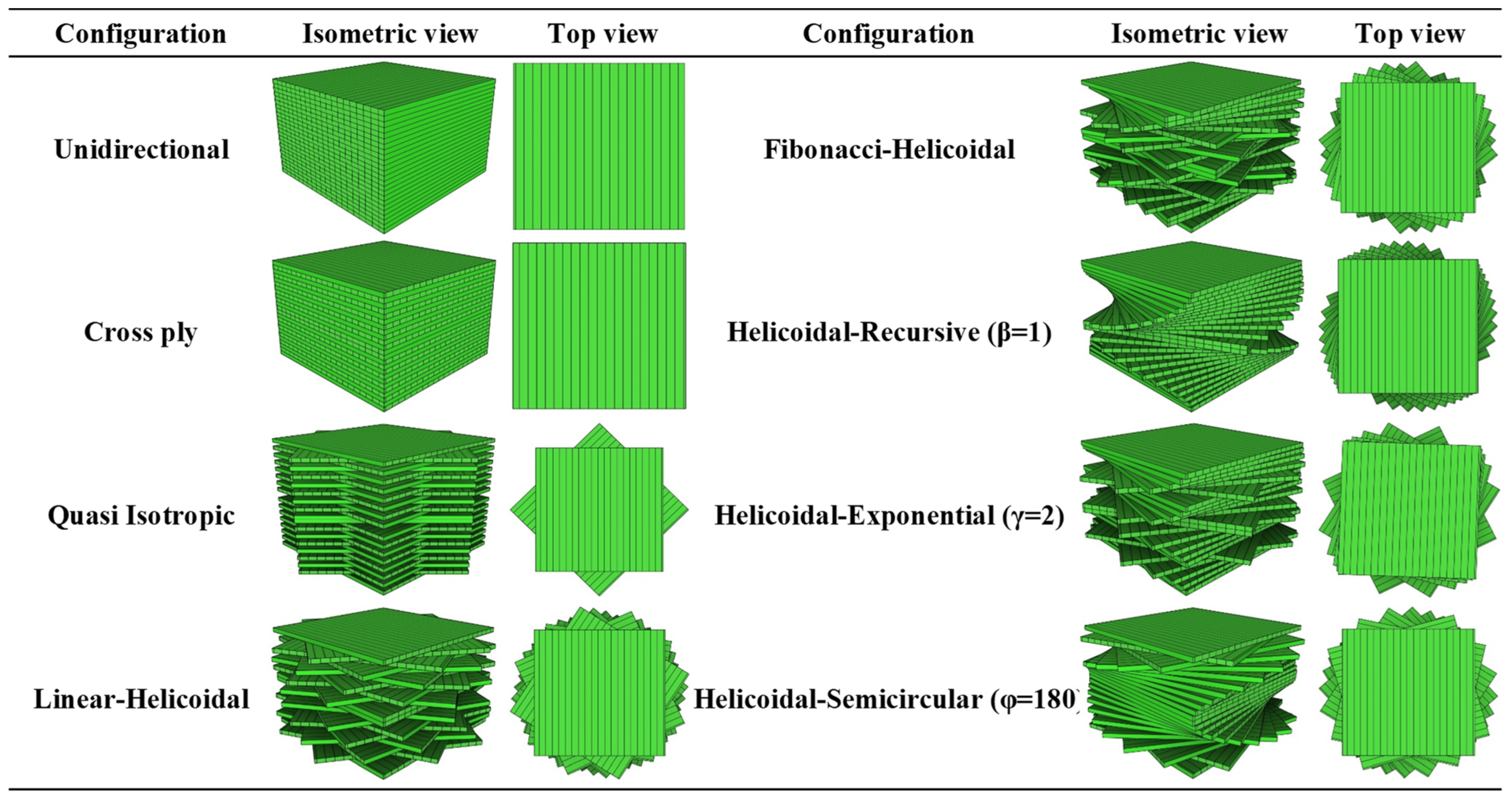
This study examines a laminated composite spherical cap; the geometric parameters and coordinate system are illustrated in Figure 1. The figure highlights the natural inspiration behind helicoidal lamination schemes and their applications in defense, medical, aerospace, and aeronautical structures. The spherical shell, with total thickness ( h ), consists of N o L perfectly bonded layers, each of equal thickness ( t ). The structure has an average radius ( R a v e ) and is subjected to arbitrary boundary conditions. This study assumes a constant radius of curvature and perfect interlayer adhesion to effectively isolate and evaluate the influence of the key geometric and lamination parameters on the structural response. Two loading types are considered: (1) an external normal radial load for normal buckling and (2) an external tangential circumferential load for torsional buckling. Five helicoidal stacking sequences—linear (LH), Fibonacci (FH), recursive (HR), exponential (HE), and semicircular (HS)—are evaluated and benchmarked against conventional unidirectional (UD), cross-ply (CP), and quasi-isotropic (QI) layups. Table 1 summarizes the mathematical relations, descriptions, and stacking sequences for each configuration. For symmetric laminates, an accurate stacking sequence requires repeating the lamina N o L 2 times with varying rotation angles before applying symmetry [38]. The HE and HS configurations exhibit nonlinear bio-inspired architectures, characterized by power-law-dependent rotation angles, while the remaining configurations adopt linear fiber orientation distributions. In the HS pattern, the ply rotation angles are determined by the expression   a n = φ 2 ( χ ( n 1 ) φ ) 2 , w h e r e   φ represents the maximum rotation angle (referring to the N o L 2 -th layer), and χ is a parameter dependent on the layer count and φ , as shown in Table 1. The nominal angular increment for φ = 180 per layer is defined as χ * = φ NoL 2 1   , where NoL denotes the total number of layers, assumed to be even. However, when χ * is not an integer, the actual angular step is obtained by rounding to the nearest integer, i.e., χ = round χ * . Figure 2 provides a schematic visualization of these configurations.
In certain cases, the ply angles listed in Table 1 for the bio-inspired helicoidal sequences—derived directly from their respective mathematical formulations—exceed 180°. However, for physical interpretation and manufacturing feasibility, these angles are interpreted modulo 180° due to the inherent material symmetry of orthotropic laminae, where ply orientations repeat every 180° (e.g., 890° ≡ 170°, 6100° ≡ 160°). This periodicity arises because the mechanical properties of a unidirectional ply are invariant under a 180° rotation. While the computational formulation remains mathematically valid for angles exceeding 180° or 360°, the physically meaningful equivalent angle within the standard range [0°, 180°) is obtained using the modulo operation. Specifically, given a ply angle (a) (dividend) and a divisor (n= 180°), the operation a   m o d   n yields the remainder after the Euclidean division of a by n, effectively reducing the angle to its equivalent within one symmetry period. This operation is efficiently implemented using MATLAB (R2021b)’s built-in ‘mod()’ function, ensuring accurate and consistent angle reduction across all helicoidal sequences.
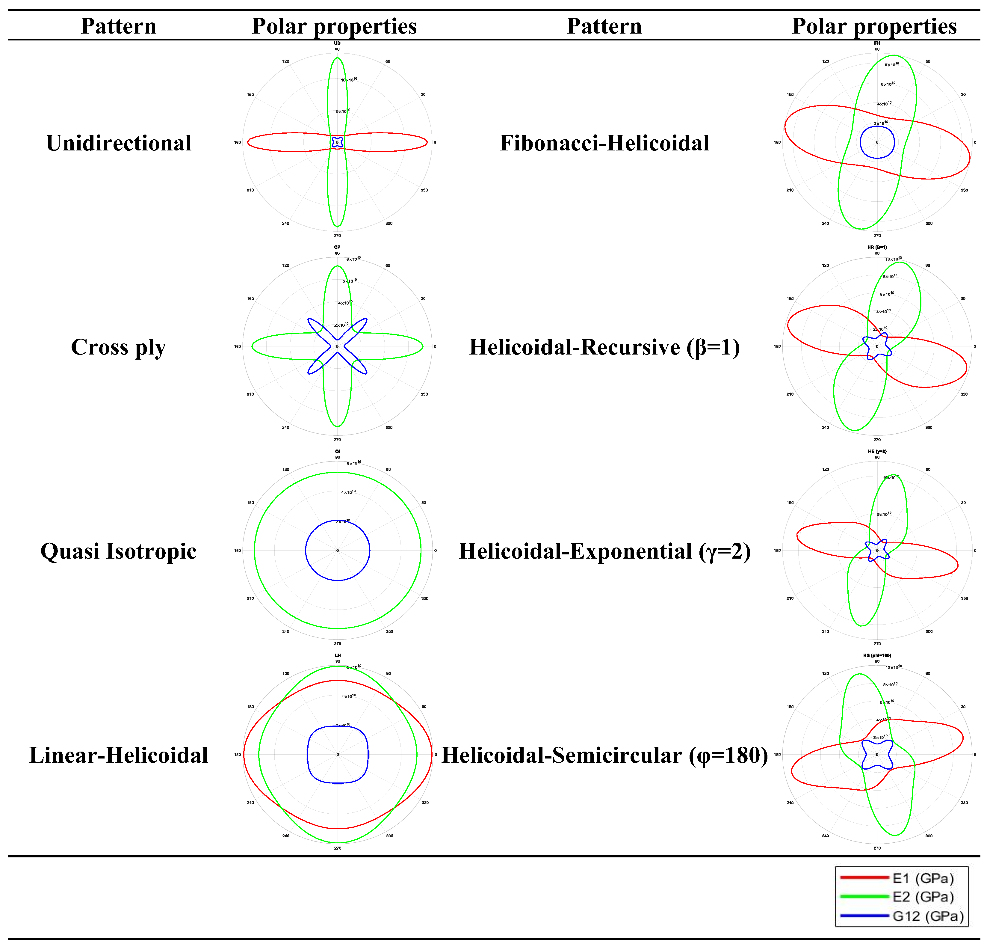
The material under investigation is linear elastic and fully orthotropic unidirectional T300/5208 carbon/epoxy, and its properties are listed in Table 2. To demonstrate the directional dependence induced by helicoidal layups, Figure 3 presents polar plots of the mechanical properties, including the principal elastic moduli ( E 1 , E 2 ) and shear moduli ( G 12 ) based on angular position. These graphs illustrate directional variations, with E 1 and E 2 aligning in CP and QI laminates.

3. Governing Equations

The buckling analysis of bio-inspired helicoid composite spherical shells is conducted using an FEM grounded in 3D linear elasticity and the principle of virtual work. The shell cap, idealized with a uniform thickness and constant curvature and defined in spherical coordinates, is discretized with an eight-node isoparametric brick element formulation, where displacements are approximated via shape functions. The material is modeled as linear elastic, with each composite ply treated as a homogenous, orthotropic continuum under the assumption of perfect bonding between laminates. The pre-buckling state, determined assuming small strains and displacements, is established by solving the equilibrium equations derived from the virtual work principle, yielding the pre-buckling deformations and stresses. For instability analysis, the critical buckling load is identified as a bifurcation point from this pre-buckling state. Geometric nonlinearity is incorporated through the Green–Lagrange strain tensor to capture the effect of finite displacements and rotations, leading to the formulation of a generalized geometric stiffness matrix derived from the pre-buckling stresses. The foundation interaction is modeled via the Winkler hypothesis, representing its reaction as linearly proportional to the radial displacement. The resulting governing equations are cast as a generalized eigenvalue problem ( K + λ K g ϕ = 0 ) , where K is the linear stiffness matrix, K g is the load-dependent geometric stiffness matrix, λ is the buckling load factor, and ϕ is the buckling-mode shape. The critical buckling load is subsequently obtained by solving this eigenvalue problem, with the smallest positive eigenvalue defining the instability point, and numerical integration ensures computational precision.
As discussed, the present formulation is grounded in a 3D elasticity framework, offering a high-fidelity benchmark by naturally accounting for both transverse shear and normal deformations without the kinematic simplifications inherent in two-dimensional equivalent-single-layer (ESL) shell theories. While ESL approaches—such as FSDT or HSDT—provide computational efficiency, and von Kármán-type nonlinear models are suitable for moderate rotations and displacements, they rely on a priori assumptions about displacement fields that may compromise accuracy for complex, multi-layered helicoidal laminates. In contrast, the 3D approach employed here enables a more rigorous and physically consistent representation of the structural stability, particularly for bio-inspired architectures with intricate material and geometric features.
As mentioned earlier, to accurately model geometric nonlinearity, the analysis adopts the Green–Lagrange strain tensor, which fully incorporates higher-order displacement gradients essential for capturing large deformations and finite rotations. This is particularly critical in composite thin-walled shells where the displacement magnitudes are comparable to or exceed the thickness, rendering linear or simplified strain measures inadequate. The use of Green strains ensures the precise prediction of the buckling modes and critical-load levels under compressive loading, especially as the thickness-to-length ratio increases, leading to enhanced structural flexibility and pronounced nonlinear softening behavior. In such regimes, simplified strain formulations like von Kármán’s, which neglect higher-order terms, tend to underestimate deformation-induced stiffness changes and may yield non-conservative predictions of the instability. Thus, the current framework is indispensable for reliably simulating the post-buckling response and failure thresholds of advanced, deformation-prone shell systems under extreme loading scenarios. This method, prioritizing 3D elasticity over simplified shell theories or von Kármán approximations, enhances accuracy by accounting for thickness effects and detailed kinematic relations, making it ideal for precise buckling load predictions.

3.1. Basic Formulations

To elucidate the geometry outlined in the preceding section, consider a spherical shell with its thickness ( h ) and average radius ( R a v e ). The shell’s outer and inner radiuses are designated as r out = b and r in = a , respectively. Defined in spherical coordinates r , θ , ϕ , where r represents the radial direction, θ (ranging from 0 to 2 π ) denotes the azimuthal angle in the x-y plane, and ϕ (ranging from 0 to π / 2 ) indicates the polar angle. The geometry is illustrated in Figure 1. This figure also depicts the stress components of the spherical cap. The stress–strain relationships are expressed in matrix notation below [41]:
σ = D ε
The stress and strain fields, along with the elasticity coefficient matrix ( D ), are formulated as follows:
σ = { σ r σ ϕ σ θ σ r ϕ σ θ ϕ σ r θ } T
ε = { ε r ε ϕ ε θ γ r ϕ γ ϕ θ γ r θ } T
D = 1 ϑ 23 ϑ 32 E 2 E 3 ϑ 21 + ϑ 23 ϑ 31 E 2 E 3 ϑ 31 + ϑ 21 ϑ 32 E 2 E 3 0 0 0 ϑ 21 + ϑ 23 ϑ 31 E 2 E 3 1 ϑ 13 ϑ 31 E 1 E 3 ϑ 32 + ϑ 12 ϑ 31 E 1 E 3 0 0 0 ϑ 31 + ϑ 21 ϑ 32 E 2 E 3 ϑ 32 + ϑ 12 ϑ 31 E 1 E 3 1 ϑ 12 ϑ 21 E 1 E 2 0 0 0 0 0 0 G 23 0 0 0 0 0 0 G 13 0 0 0 0 0 0 G 12
Δ = 1 υ 12 υ 21 υ 23 υ 32 υ 13 υ 31 2 υ 21 υ 32 υ 13 E 1 E 2 E 3
υ i j E i = υ j i E j
The strain field, grounded in linear elasticity theory within spherical coordinates, is expressed as follows:
ε =   ε L + ε N L
in which
ε L = u r 1 r u + v ϕ 1 r sin ϕ w θ + sin ϕ u + cos ϕ v 1 r u ϕ + v r v r 1 r 1 sin ϕ v θ + w ϕ cot ϕ w 1 r sin ϕ u θ + w r w r
and
ε N L = 1 2 u r 2 + v r 2 + w r 2 1 2 1 r u ϕ v 2 + 1 r u + v ϕ 2 + 1 r w ϕ 2 1 2 1 r sin ϕ u θ w sin ϕ 2 + 1 r sin ϕ v θ w cos ϕ 2 + 1 r sin ϕ w θ + u r + v cot ϕ r 2 1 r u r u ϕ v + 1 r v r v ϕ + u + 1 r w r w ϕ 1 r 2 sin ϕ u ϕ v u θ w sin ϕ + 1 r 2 sin ϕ v ϕ + u v θ w cos ϕ + 1 r w ϕ 1 r sin ϕ w θ + u r + v cot ϕ r 1 r sin ϕ u r u θ w sin ϕ + 1 r sin ϕ v r v θ w cos ϕ + w r 1 r sin ϕ w θ + u r + v cot ϕ r
Additionally, u, v, and w represent the displacement components along the r, ϕ , and θ directions, respectively. Based on these relationships, the linear strain relationship can be reformulated as follows:
ε L = L Q
in which Q represents the displacement vector and L is a matrix comprising partial differential operators, expressed as follows:
Q = { u v w } T
L = r 1 r 1 r 1 2 r ϕ 0 1 2 r sin ϕ θ 0 1 r ϕ 1 r cot ϕ 1 2 r 1 2 r 1 2 r sin ϕ θ 0 0 0 1 r sin ϕ θ 0 ϕ cot ϕ r 1 r T

3.2. Finite Element Modeling

To address the governing equations, an FEM approach is employed. The spherical shell is discretized into eight-node linear brick elements. For each element (e), the displacements in the three coordinate directions are approximated as follows [41]:
Q ( e ) = Φ Λ ( e )
where Φ denotes the matrix of linear shape functions in spherical coordinates, and Λ ( e ) represents the nodal displacement vector for the element (e), expressed as follows:
Φ = Φ 1 0 0 Φ 8 0 0 0 Φ 1 0 0 Φ 8 0 0 0 Φ 1 0 0 Φ 8
and
Λ ( e ) = { U 1 V 1 W 1 U 8 V 8 W 8 } T
The components of the shape function matrix ( Φ ) are defined as follows:
Φ i = 1 V Γ X
where the volume of each element, represented as V , is defined as follows:
V = 1 ξ 1 η 1 ζ 1 ξ 1 η 1 ξ 1 ζ 1 η 1 ζ 1 ξ 1 η 1 ζ 1 1 ξ 2 η 2 ζ 2 ξ 2 η 2 ξ 2 ζ 2 η 2 ζ 2 ξ 2 η 2 ζ 2 1 ξ 3 η 3 ζ 3 ξ 3 η 3 ξ 3 ζ 3 η 3 ζ 3 ξ 3 η 3 ζ 3 1 ξ 4 η 4 ζ 4 ξ 4 η 4 ξ 4 ζ 4 η 4 ζ 4 ξ 4 η 4 ζ 4 1 ξ 5 η 5 ζ 5 ξ 5 η 5 ξ 5 ζ 5 η 5 ζ 5 ξ 5 η 5 ζ 5 1 ξ 6 η 6 ζ 6 ξ 6 η 6 ξ 6 ζ 6 η 6 ζ 6 ξ 6 η 6 ζ 6 1 ξ 7 η 7 ζ 7 ξ 7 η 7 ξ 7 ζ 7 η 7 ζ 7 ξ 7 η 7 ζ 7 1 ξ 8 η 8 ζ 8 ξ 8 η 8 ξ 8 ζ 8 η 8 ζ 8 ξ 8 η 8 ζ 8
and
Γ i j = 1 i + j A i j
X = { 1 , ξ , η , ζ , ξ η , ξ ζ , η ζ , ξ η ζ } T
where
ξ = r cos θ sin φ , η = r sin θ sin φ , ζ = r cos φ
ξ i = r i cos θ i sin φ i , η i = r i sin θ i sin φ i , ζ i = r i cos φ i
in which r i , θ i , and ϕ i denote the nodal coordinates, and A i j is derived by removing the i-th row and j-th column from the volume matrix ( V ). By substituting Equation (9) into Equation (6), the strain matrix for the element (e) is obtained as follows:
ε L ( e ) = B Λ ( e )
in which
B = L Φ ( e )
The FEM governing equations are derived from the principle of virtual work, where the system’s potential energy ( U ) and the external load’s virtual work ( δ W ) are defined as follows:
δ Π = δ U δ W = 0
where
δ U = V e δ ε e T σ e d V + A K W u δ u d A r = b
d V = r 2 sin ϕ   d r d ϕ d θ
d A = r 2 sin ϕ   d ϕ d θ
The second term in the δ U is the potential energy of the Winkler elastic foundation, which is exerted to the outer surface of the spherical cap. In fact, K w is the stiffness of the Winkler elastic foundation (or modulus of the subgrade reaction) with units of force per unit volume (MN/m3). The elastic support at the boundary is modeled using the Winkler foundation approach, a well-established method that idealizes the supporting medium as a bed of closely spaced, independent, linear springs. In this model, the foundation’s reaction pressure at any point is directly proportional to the local radial displacement at that point. This parameter is incorporated into the finite element model via the global stiffness matrix.
However,
N o r m a l   L o a d i n g   : δ W = A σ ¯ r r δ u d A r = b T o r s i o n a l   L o a d i n g   : δ W = A σ ¯ r θ δ w d A r = b
Here, A represents the area under the external radial load, σ ¯ r r = 1 corresponds to normal buckling, and σ ¯ r θ = 1 applies to torsional buckling, both acting on the spherical shell’s external surface. In the pre-buckling state, displacements are assumed small, causing the strain–displacement relations’ nonlinear terms to diminish. Thus, the following simplification holds:
δ U = V e δ ( B Λ e ) T D B Λ e d V + δ Λ ( e ) T N ¯ T K w N ¯ d A r = b Λ ( e ) = δ Λ ( e ) T ( K + K w ) Λ ( e )
N ¯ = 0 0 0 0 0 0 0 0 0 0 0 0 N 5 0 0 N 6 0 0 N 7 0 0 N 8 0 0 0 0 0 0 0 0 0 0 0 0 0 0 0 0 0 0 0 0 0 0 0 0 0 0 0 0 0 0 0 0 0 0 0 0 0 0 0 0 0 0 0 0 0 0 0 0 0 0
Consequently, in the pre-buckling stage, based on the virtual work principle, the static equilibrium equation for each element can be expressed as follows:
δ Λ ( e ) T V ( e ) B T D B d V Λ ( e ) + δ Λ ( e ) T N ¯ T K w N ¯ d A r = b Λ ( e ) = δ Λ ( e ) T A ( e ) φ T p d A
Equation (26) can be expressed in compact form, as below:
( K e + K w ) Λ e = F e
in which K e represents the element linear stiffness matrix, K w is the stiffness matrix due to the elastic foundation, and F e denotes the corresponding elemental force matrix, defined as follows:
K e = V e B T D   B d V K w = N ¯ T K w N ¯ d A r = b
and
F e = A e F T p d A
in which
N o r m a l   L o a d   : p = σ ¯ r r 0 0 r = b T o r s i o n a l   L o a d   : p = 0 0 σ ¯ r θ r = b
Through assembly of the elemental matrices, the global equilibrium equation governing the spherical cap in its pre-buckling configuration is derived as follows:
K + K w Λ = F
The solution of the governing equations yields the pre-buckling deformation field under unit loading conditions: σ ¯ r r = 1 for normal-buckling analysis and σ ¯ r θ = 1 for torsional-buckling analysis. The resulting stress field is subsequently incorporated into the geometric stiffness matrix formulation. For instability analysis, the critical buckling condition is established through the following relationship between the pre-buckling state and onset of instability:
δ δ Π = δ 2 Π = 0
Consequently, through combination of Equations (27) and (31), the following relationship is obtained:
δ Λ e T K e + K w   δ Λ ( e ) + δ 2 Π E x t . = 0
Equation (5) demonstrates that the shell’s strain energy incorporates both linear and nonlinear strain–displacement components. During the pre-buckling phase, radial displacements remain sufficiently small to neglect nonlinear effects, reducing the formulation to linear strain terms exclusively. However, at the onset of buckling, the nonlinear strain–displacement components become significant. Consequently, the following relationship emerges exclusively in the post-buckling regime:
U = Π E x t . = 1 2 V ε n l T σ d V
The external work potential, Π E x t . , can be reformulated as follows:
E x t = 1 4 V ( e ) ψ T Θ ψ d V = 1 4 ( V ( e ) Ξ Q T Θ Ξ Q d V )
in which
ψ T = u r 1 r u ϕ v 1 r sin ϕ u θ w sin ϕ v r 1 r u + v ϕ 1 r sin ϕ v θ w cos ϕ w r 1 r w ϕ 1 r sin ϕ w θ + u r + v cot ϕ r 1 × 9
ψ 9 1 = Ξ 9 3 Q
and
Ξ = r 0 0 1 r ϕ 1 r 0 1 r sin ϕ θ 0 1 r 0 r 0 1 r 1 r ϕ 0 0 1 r sin ϕ θ cot ϕ r 0 0 r 0 0 1 r ϕ 1 r cot ϕ r 1 r sin ϕ θ
Θ = S 0 0 3 * 3 0 3 * 3 0 3 * 3 S 0 0 3 * 3 0 3 * 3 0 3 * 3 S 0
S 0 = σ 0 r r σ 0 r ϕ σ 0 r θ σ 0 r ϕ σ 0 ϕ ϕ σ 0 ϕ θ σ 0 r θ σ 0 ϕ θ σ 0 θ θ
In the discussed formulation, S 0 denotes the pre-buckling stress field. Through substitution of the relation Q ( e ) = Φ Λ ( e ) , we derive the following:
ψ = Ξ Φ Λ ( e )
in which
Ω = Ξ Φ
For a rigorous formulation, the discussed matrix can be systematically derived as follows:
Ω = ϕ 1 r 0 0 ϕ 8 r 0 0 1 r ϕ 1 ϕ ϕ 1 r 0 1 r ϕ 8 ϕ ϕ 8 r 0 1 r sin ϕ ϕ 1 θ 0 ϕ 1 r 1 r sin ϕ ϕ 8 θ 0 ϕ 8 r 0 ϕ 1 r 0 0 ϕ 8 r 0 ϕ 1 r 1 r ϕ 1 ϕ 0 ϕ 8 r 1 r ϕ 8 ϕ 0 0 1 r sin ϕ ϕ 1 θ ϕ 1 cot ϕ r 0 1 r sin ϕ ϕ 8 θ ϕ 8 cot ϕ r 0 0 ϕ 1 r 0 0 ϕ 8 r 0 0 1 r ϕ 1 ϕ 0 0 1 r ϕ 8 ϕ ϕ 1 r ϕ 1 cot ϕ r 1 r sin ϕ ϕ 1 θ ϕ 8 r ϕ 8 cot ϕ r 1 r sin ϕ ϕ 8 θ
Hence, in accordance with Equation (33), we obtain the following:
δ 2 Π = δ Λ e T K e + K w δ ( Λ ( e ) ) + δ ( Λ ( e ) T ) ( V ( e ) Ω T Θ Ω d V ) δ ( Λ ( e ) ) = 0
A rearrangement of Equation (33) yields
δ Λ e T   K e + K w + K G e δ Λ e = 0
Following the assembly of the element matrices, the structure’s determinant must be set to zero:
K e + K w + K G = 0
V e B T D B d V + N ¯ T K w   N ¯ d A r = b λ C r V e Ω T Θ Λ Ω d V = 0
Here, K G denotes the geometric stiffness matrix, evaluated using the eight-point Gaussian quadrature.

4. Numerical Solution

This section presents comprehensive parametric studies examining the buckling response of bio-inspired helicoidal laminated composite spherical shells under normal and torsional loads with elastic support, following the solution methodology outlined in Section 3. Key parameters analyzed include the loading conditions (normal/torsional), lamination schemes, ply counts, polar angles, shell thickness, Winkler foundation stiffness, and boundary conditions. Results are systematically presented in tabular and graphical formats to facilitate interpretation. Prior to discussing the novel findings, validation and verification studies are first presented in Section 4.1 to confirm the accuracy and reliability of the proposed computational approach.

4.1. Verification Studies

The correctness of the developed numerical methodology was verified through systematic comparisons with established literature results. Table 3 presents a comparative analysis of the normal-buckling loads for 304 stainless-steel hemispherical shells subjected to uniform external pressure, validating our results against the experimental and numerical data from Zhang et al. [42]. The referenced study investigated six laboratory-scale specimens with nominal dimensions ( t = 1   m m , d = 146   m m , h = 37   m m ), accounting for measured thickness variations ( 1 ± 0.0212   m m ), which produced six distinct buckling loads. Our 3D elasticity-based solution methodology, cross-verified using ANSYS Workbench (2021 R2), shows excellent correlation with both the experimental measurements and finite element results from Zhang et al. [42], including their ABAQUS simulations employing elastic–perfectly plastic and elastic–plastic constitutive models. The close agreement between our computed results (for t = 1   m m ) and the reference values (averaged across all six specimens) confirms the accuracy of our computational approach.
The normal-buckling behavior was further validated by comparing the first four buckling modes of isotropic copper spherical caps with varying polar angles against the numerical results of Zhou et al. [41] in Table 4. The referenced study employed 3D elasticity theory combined with finite element analysis as well as ANSYS Workbench. This analysis examined a homogeneous spherical cap with the following characteristics: inner radius: R i n = 0.225   m ; outer radius: R o u t = 0.25   m ; and material properties: E m = 130   G P a , ρ m = 8960   k g / m 3 , and ν m = 0.34 . The present results demonstrate remarkable consistency with Zhou et al.’s [41] predictions, as evidenced by the close agreement in the mechanical characteristics across all investigated cases.
The close agreement between our computational results and the reference data from both experimental and numerical studies [41,42] demonstrates the validity and reliability of the proposed solution methodology. The excellent correlation with the established results in the literature verifies the numerical precision and computational efficiency of our implementation, providing a solid foundation for the subsequent parametric investigations presented in this study.

4.2. Results and Discussion

This section presents a comprehensive numerical analysis of the buckling behavior of bio-inspired helicoid composite spherical shells subjected to normal and torsional loading while supported on a Winkler-type elastic foundation. This study systematically examined the influence of the loading type, lamination scheme, ply count, polar angle, shell thickness, Winkler foundation stiffness, and boundary conditions. All analyses were conducted with a fixed average shell radius of R a v e = 1   m as the reference geometry, with all other dimensional quantities expressed as ratios relative to R a v e . Two distinct boundary conditions were considered:
C l a m p e d   ( C ) : u = v = w = 0  
S i m p l y   s u p p o r t e d   ( S ) : N o r m a l   B u c k l i n g   : u = w = 0 T o r s i o n a l   B u c k l i n g   : v = w = 0
Table 5 presents the initial numerical findings, illustrating the effects of the normal- and torsional-loading conditions, lamination schemes, and associated configuration parameters on the buckling behavior of the helicoid composite hemispherical shells. In contrast to conventional layup sequences, the ply angles in helicoidal patterns are not arbitrarily chosen but are systematically determined by mathematical expressions that define the bio-inspired stacking architectures, as specified in Table 1. This ensures a controlled and reproducible angular progression that mimics natural structural motifs, allowing for a precise correlation between the targeted mechanical performance and the resulting laminate configuration. The configuration parameters were varied within common established ranges from the literature to assess their influence. Under normal-buckling loads, the UD pattern exhibited the poorest performance, whereas the cross-ply (CP) configuration was the least effective for torsional loading. In both loading scenarios, the quasi-isotropic (QI) lamination demonstrated optimal buckling resistance, yielding the highest critical loads. Helicoidal configurations displayed intermediate buckling capacities. For both normal and torsional buckling, the performance rankings—ordered from lowest to highest critical load—are provided in the right-hand side of Table 5 to enable a direct and clear comparison across the analyzed laminate configurations.
Table 6 examines the effects of the normal- and torsional-load conditions, layup sequences, and layer count on the buckling responses of the helicoid hemispherical laminated shells. Generally, increasing the number of layers enhanced the buckling resistance in most configurations—such as the QI, FH, HR (β = 1), HE (γ = 2), and HS (φ = 180°) patterns—exhibiting a clear ascending trend. In contrast, the UD, CP, and LH patterns display negligible variations. The layer count exerted the most pronounced influence on the HE configuration (γ = 2), followed by the HR (β = 1), FH, HS (φ = 180°), QI, LH, CP, and UD configurations, in descending order. Reducing layers from 32 to 24 and 16 yielded a negligible change in the UD, CP, and LH configurations. However, the QI, HS (φ = 180°), FH, HR (β = 1), and HE (γ = 2) patterns exhibited buckling load reductions, with respective reduction factors of 0.95, 0.95, 0.92, 0.89, and 0.72, ranked in ascending order of severity.
Table 7 presents the next numerical investigation, analyzing the effects of the normal- and torsional-loading conditions, lamination sequence, and thickness ratio on the buckling behavior of the helicoid hemispherical laminated shells. In this study, the average radius ( R a v e ) was maintained constant at unity; thus, increasing the thickness ratio resulted in a slenderer shell geometry. As anticipated, higher thickness ratios led to significant reductions in both the normal- and torsional-buckling capacities. On average, doubling the thickness ratio (e.g., from 10 to 20 or 20 to 40) reduced the normal-buckling capacity by a factor of 6.12, while the torsional-buckling capacity decreased by a factor of 5.92, indicating a more pronounced sensitivity to thickness variation under normal loading. For normal buckling, the CP pattern exhibited the strongest thickness dependency, with an average reduction factor of 7.22 when the thickness ratio was doubled. In contrast, the UD configuration showed the least sensitivity, with a reduction factor of 4.62. Under torsional loading, the FH pattern was the most affected by thickness changes (average reduction factor: 7.63), while the CP configuration demonstrated the lowest sensitivity (factor: 3.82).
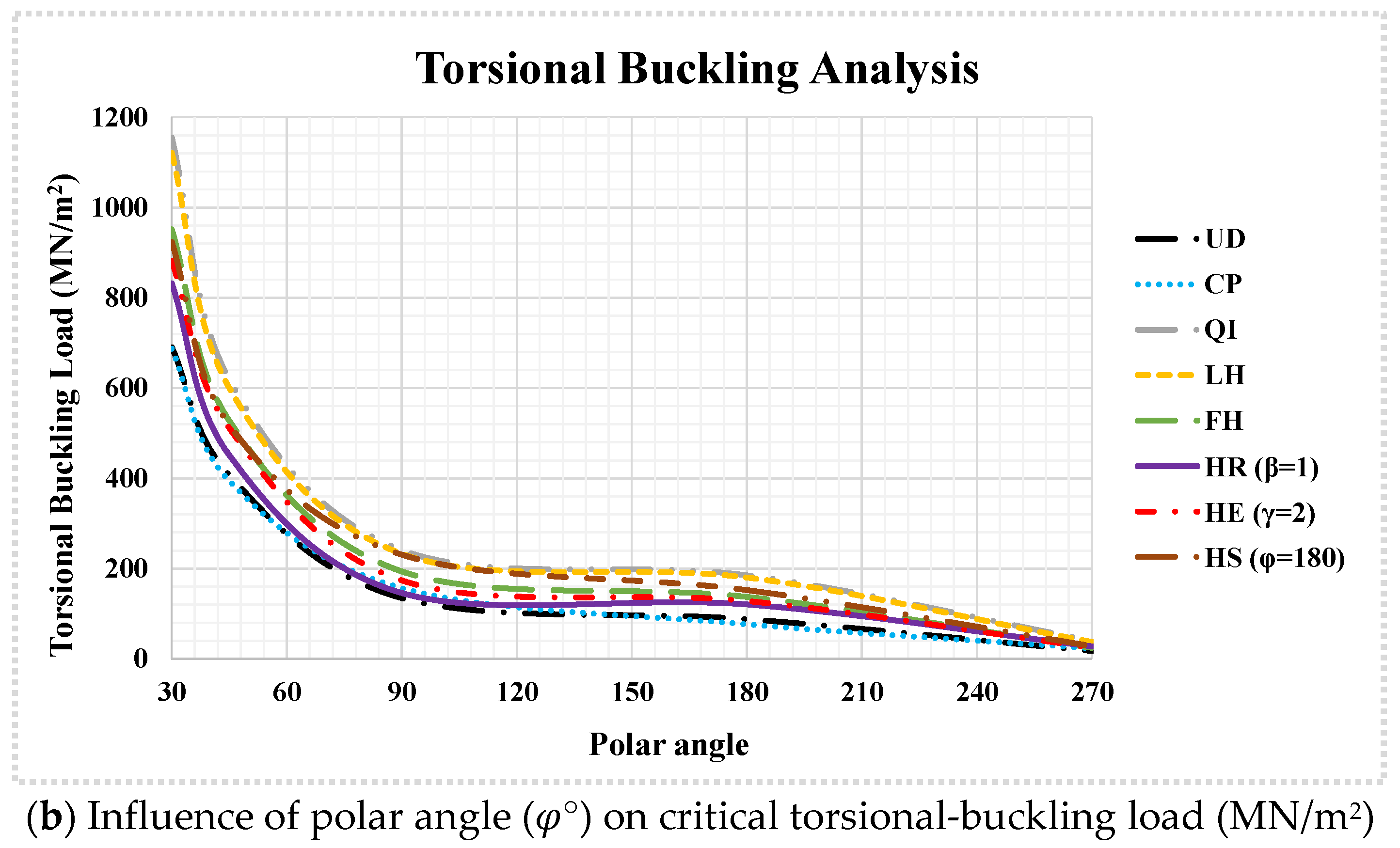
Figure 4 illustrates the effects of the polar angle and lamination pattern on the (a) normal- and (b) torsional-buckling behavior of the bio-inspired spherical laminated shells. The results reveal that the buckling loads generally decreased with the increasing polar angle, and this dependence became less pronounced at larger angles. For normal buckling, tripling the polar angle from 30° to 90° reduced the average first-mode buckling load by a factor of 1.80 across all patterns, whereas a similar angular increase from 90° to 270° yielded only a 1.36-fold reduction. This demonstrates a nonlinear relationship, where the rate of load reduction diminishes with the increasing polar angle. Torsional buckling exhibited significantly greater sensitivity to polar angle variations. When the polar angle expanded from 30° to 270°, the average first-mode torsional-buckling capacity decreased by a factor of 32.51, compared to just 2.44 for normal buckling. Figure 5 presents the buckling-mode shapes of the bio-inspired spherical laminated shells across varying polar angles and load cases, providing insight into their deformation characteristics.
Although polar angles greater than 180° are infrequently encountered in conventional engineering applications, their consideration is crucial for accurately capturing the nonlinear decay and asymptotic trends in buckling loads, particularly in elucidating the pronounced sensitivity of torsional buckling to geometric variations. While partial spherical shells with a polar angle of 90° and hemispherical shells (polar angle = 180°) represent the most practically relevant configurations, structures with larger polar angles also find application in specialized domains. For instance, deep-sea pressure hulls in submersibles, biological systems such as mollusk shells and echinoids, and architectural domes incorporating deep partial spherical segments exemplify real-world systems where extended polar angles are functionally significant. These cases underscore the importance of extending the analysis beyond the hemisphere to encompass broader geometric configurations.
Complementing this, Table 8 systematically examines the effects of the normal- and torsional-loading conditions, lamination patterns, polar angle, and boundary constraints on the buckling behavior of bio-inspired helicoidal laminated composite spherical shells. The results demonstrate that reduced boundary constraints (e.g., transitioning from clamped to simply supported) or increased polar angles consistently diminished the buckling capacities. For instance, in hemispherical shells (polar angle = 180°), relaxing the boundary condition from clamped to simply supported reduced normal-buckling loads by an average factor of 1.28 across all lamination patterns and modes, while torsional buckling decreased by a factor of 1.16. This differential sensitivity highlights the more substantial influence of the boundary conditions on normal-buckling behavior. In contrast, spherical shells with a 90° polar angle exhibited more pronounced reductions, with factors of 1.38 and 1.56 for normal and torsional buckling, respectively. This indicates greater sensitivity to boundary conditions in shells with smaller polar angles. Furthermore, for clamped shells under normal loading, doubling the polar angle from 90° to 180° reduced the buckling capacity by an average factor of 1.27, whereas torsional buckling showed a stronger dependence, with a reduction factor of 1.49. Under simply supported conditions, these factors decreased to 1.19 and 1.11, respectively, suggesting minimal variation between the load types for less constrained boundaries.
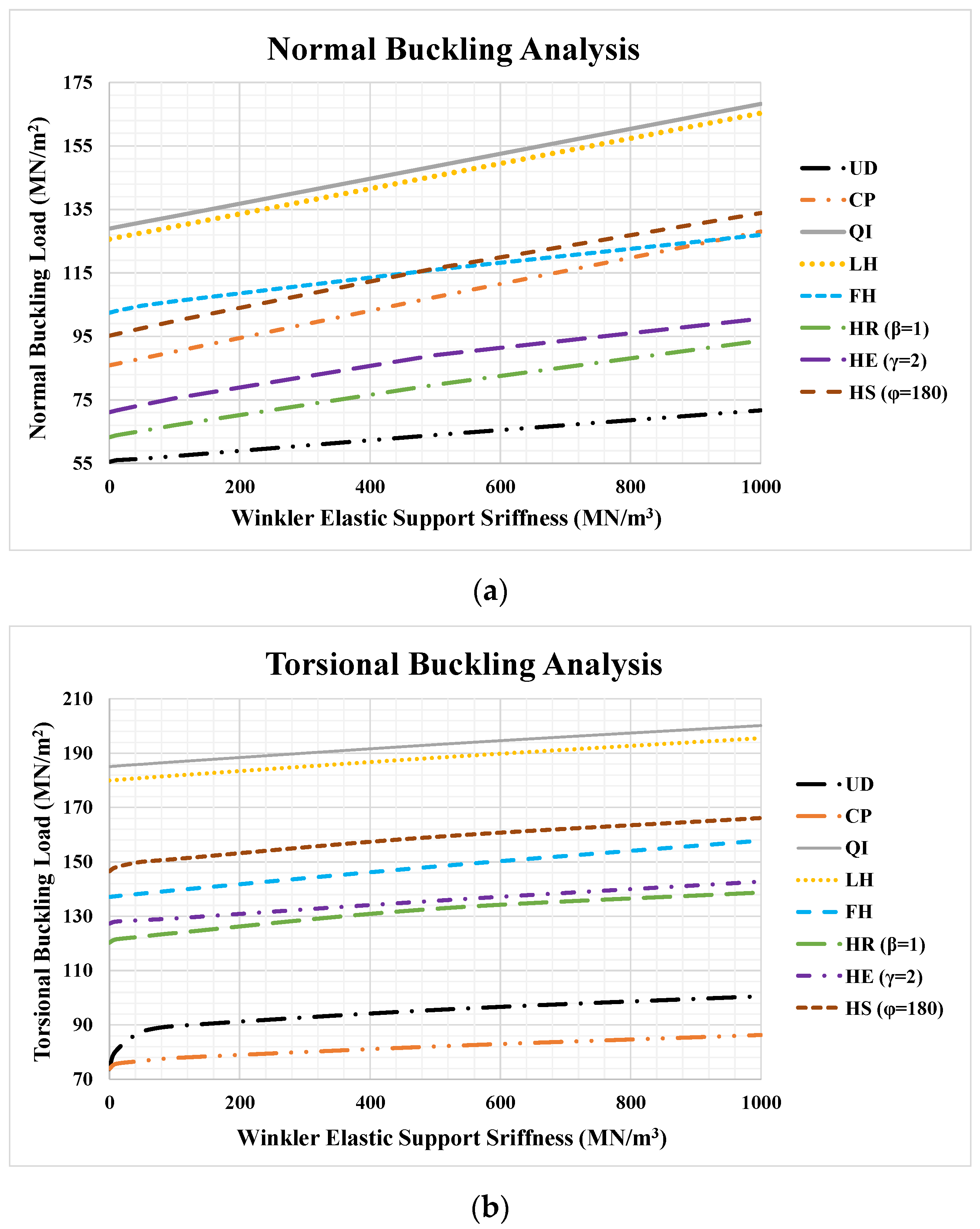
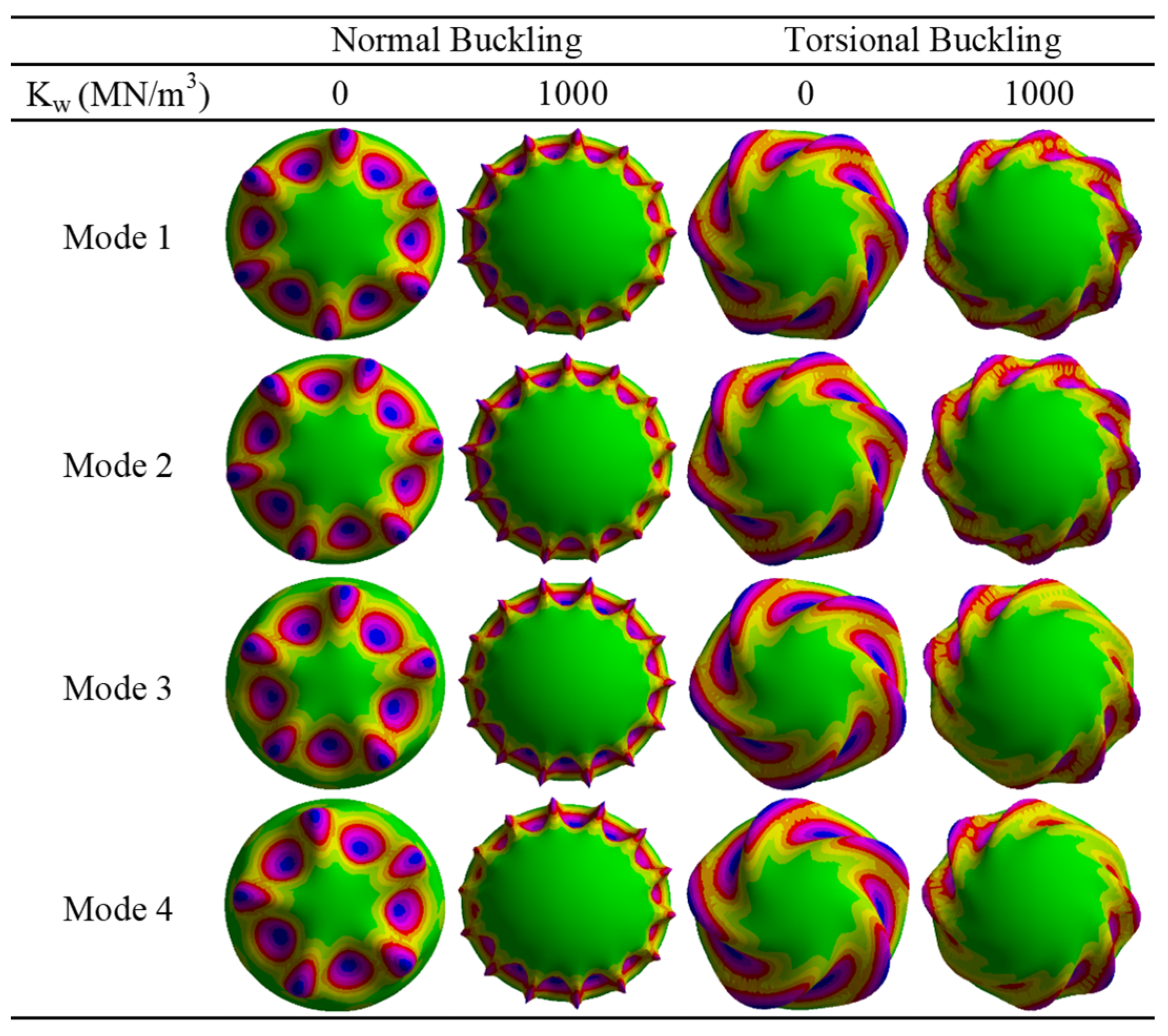
Figure 6 examines the effects of the Winkler elastic medium parameter, loading conditions, and lamination patterns on the (a) normal- and (b) torsional-buckling responses of helicoid hemispherical laminated shells. As anticipated, enhanced foundation stiffness elevated the buckling resistance for both the normal- and torsional-loading scenarios, though its influence was markedly more pronounced for normal buckling. Specifically, increasing the Winkler stiffness from 0 to 1000 MN/m3 augmented the normal-buckling capacity by a factor of 1.36, compared to a marginal 1.14-fold improvement for torsional buckling, based on averaged results across all lamination configurations. Figure 7 illustrates the influence of the elastic foundation on the buckling-mode shapes of the bio-inspired laminated hemispherical shells, considering both normal- and torsional-buckling modes. As previously observed, the elastic support demonstrates a more remarkable effect on normal buckling compared to the torsional case. Furthermore, the presence of elastic support generated more localized deformation patterns characterized by higher wave numbers and increased modal humps.
The Winkler foundation stiffness parameter was systematically varied from 0 (fully unsupported) to 1000 MN/m3 to enable a comprehensive parametric investigation encompassing a broad spectrum of structural support conditions. This range was carefully selected to reflect both conventional and high-performance engineering applications, thereby ensuring the relevance of the analysis across diverse real-world scenarios. Lower values (10–200 MN/m3) correspond to typical geotechnical and compliant media, including soft to stiff clays, compacted sands, fluid substrates, and elastic pads—conditions commonly associated with buried infrastructure such as storage tanks. In contrast, medium to high stiffness values (200–1000 MN/m3) represent more rigid support systems, such as sandwich structures with rigid polymeric or metallic foam cores, elastomeric mountings in aerospace components, composite panels with fiber-reinforced cores, and concrete-encased elements in civil engineering systems. The upper bound of 1000 MN/m3 serves as a conservative limit, modeling extreme confinement cases such as nuclear containment vessels or deeply embedded marine hulls. By spanning this full spectrum, the parametric variation in K w facilitates the representation of intermediate boundary conditions between idealized clamped and free edges, significantly improving the fidelity of predicted stress distributions, deformation patterns, and stability responses in structural systems.
The enhanced buckling resistance observed in bio-inspired helicoidal laminates, as quantified in the present results, can be attributed to a confluence of synergistic physical mechanisms inherent to their architecture. Primarily, the gradual, continuous rotation of the fiber orientation through the laminate thickness creates a smooth gradient in mechanical properties, as seen in Figure 3, effectively mitigating the sharp anisotropy and deleterious stress concentrations that characterize traditional unidirectional or cross-ply interfaces and often serve as initiation points for instability. This architecture fosters superior interlaminar shear transfer, distributing stresses more uniformly and providing enhanced resistance to torsional-buckling modes. Furthermore, the progressive rotation enables the laminate to approach a near quasi-isotropic in-plane stiffness profile, allowing for highly efficient multi-axial load redistribution and increasing the overall structural stiffness under different loads. Finally, inheriting the damage tolerance of their biological analogues, these helicoidal structures impede crack propagation and delamination by forcing micro-cracks to follow a tortuous, energy-dissipating path, thereby preserving the structural integrity and load-bearing capacity up to a higher critical buckling threshold. These mechanisms—anisotropy smoothing, enhanced shear transfer, near quasi-isotropic response, and inherent damage tolerance—collectively underpin the superior performance of helicoidal laminates.
Although the current model evaluates the structural-scale buckling behavior through homogenized orthotropic ply-level properties, the superior performance of bio-inspired helicoidal laminates, in practice, fundamentally originates from micro-mechanical interactions at the fiber/matrix interface. The progressive rotation of plies facilitates effective interlaminar shear stress transfer, mitigates localized stress concentrations, and promotes crack deflection within the matrix phase, collectively inhibiting delamination onset and enhancing damage tolerance. These microstructural mechanisms underpin the observed improvement in macroscopic buckling resistance, offering a mechanistic explanation for the enhanced structural performance.
The superior buckling resistance and stability of bio-inspired helicoidal laminated composite spherical shells, as demonstrated in this study, suggest several promising practical applications. In aerospace and defense, these shells could be employed in satellite housings, radomes, or impact-resistant casings, where normal and torsional loads from launch vibrations or impacts necessitate robust, lightweight designs. In marine engineering, submersible hulls or underwater storage modules could benefit from the shells’ superior performance under external hydrostatic pressure, with the elastic foundation modeling reflecting real-world support conditions. For civil structures, such as underground tanks or containment domes on elastic foundations, the improved stability is critical against seismic or pressure-induced buckling. Furthermore, the bio-inspired nature of these designs extends their potential to biomedical fields, including durable artificial joint implants. These applications underscore the potential of helicoidal architectures to translate natural structural optimization into high-performance engineering solutions.

5. Conclusions

This study investigated the buckling behavior of bio-inspired helicoidal laminated composite spherical shells subjected to normal and torsional loading, while accounting for the influence of a Winkler elastic foundation. The research explored the buckling performances of various helicoidal stacking sequences benchmarked against conventional laminates. Using 3D linear elasticity theory combined with the principle of virtual work and FEA, we established the equilibrium equations governing the pre-buckling state. The critical buckling load was subsequently computed through a nonlinear formulation incorporating Green–Lagrange strains and generalized geometric stiffness concepts. A comprehensive parametric study assessed the effects of the lamination scheme, ply count, polar angle, shell thickness, boundary conditions, and elastic foundation stiffness on the buckling resistance. The key findings of this research are summarized as follows:
-
Quasi-isotropic (QI) lamination consistently delivered the highest buckling resistance under both normal and torsional loads, while unidirectional (UD) and cross-ply (CP) configurations exhibited the poorest performances in normal and torsional buckling, respectively.
-
For normal buckling, the performance rankings (from lowest to highest) are as follows: UD, HR (β = 1), HS (φ = 45°), HE (γ = 2), HE (γ = 3), HS (φ = 90°), CP, HE (γ = 2.5), HR (β = 2), HS (φ = 180°), FH, HR (β = 3), LH, and QI.
-
In terms of the torsional-buckling performance, the ranking order from lowest to highest is as follows: CP, UD, HR (β = 2), HR (β = 1), HE (γ = 3), HE (γ = 2), HS (φ = 45°), HR (β = 3), FH, HE (γ = 2.5), HS (φ = 90°), HS (φ = 180°), LH, and QI.
-
Increasing the number of layers generally enhanced the buckling resistance for QI and helicoidal (FH, HR, HE, HS) laminations, with HE configurations (γ = 2) exhibiting the most pronounced sensitivity. In contrast, UD, CP, and LH configurations showed negligible changes in the buckling load regardless of the layer count.
-
Increasing the thickness ratio (reducing the relative thickness) drastically reduced the buckling capacity, with normal buckling showing greater sensitivity than torsional buckling. CP laminations were most affected by thickness changes under normal loads, while UD configurations were the least sensitive. Conversely, under torsional loads, FH laminations exhibited the highest thickness dependency, whereas CP laminations proved the most resilient.
-
Both reduced boundary constraints (clamped → simply supported) and an increased polar angle significantly diminished the buckling capacity, with smaller polar angles exhibiting greater sensitivity to boundary conditions. Additionally, clamped shells displayed stronger polar angle dependency under torsional loads compared to normal loads. In contrast, simply supported shells showed minimal load-type dependence, underscoring the critical interplay between the geometry, boundary conditions, and loading regime in spherical shells.
-
Increasing the polar angle reduced the buckling loads nonlinearly, with diminishing sensitivity at larger angles. Crucially, torsional buckling exhibited extreme polar angle dependence—expanding from 30° to 270°, causing a 32.51× reduction, far exceeding the 2.44× drop for normal loads.
-
Increasing the Winkler-type elastic foundation stiffness enhanced the buckling resistance, with normal buckling exhibiting a 1.36× improvement (from 0 to 1000 MN/m2) compared to only 1.14× for torsional buckling. This reveals that elastic support significantly improves the normal-load-bearing capacity while having relatively modest effects on the torsional stability. Similarly, mode shape analysis reveals that elastic foundations exert a more pronounced effect on normal-buckling-mode shapes than on torsional ones, inducing localized deformation patterns with elevated wave numbers and intensified modal humps.

Author Contributions

Conceptualization, M.J.B., A.K., M.B. and K.A.; Methodology, M.J.B., A.K., M.B. and K.A.; Software, M.J.B. and A.K.; Validation, M.J.B., A.K., M.B. and K.A.; Formal analysis, M.J.B., A.K., M.B. and K.A.; Investigation, M.J.B., A.K. and M.B.; Data curation, M.J.B. and A.K.; Writing – original draft, M.J.B. and A.K.; Writing – review & editing, A.K., M.B. and K.A.; Supervision, K.A. All authors have read and agreed to the published version of the manuscript.

Funding

The authors received no financial support for the research, authorship, or publication of this article.

Data Availability Statement

Data will be made available upon request.

Conflicts of Interest

The authors declare no known competing financial interests or personal relationships that could have appeared to influence the work reported in this paper. All authors affirm that they have no organizational affiliations, financial relationships, or personal connections that could constitute a conflict of interest regarding the subject matter or findings discussed in this manuscript.

References

  1. Wang, D.; Zaheri, A.; Russell, B.; Espinosa, H.; Zavattieri, P. Fiber reorientation in hybrid helicoidal composites. J. Mech. Behav. Biomed. Mater. 2020, 110, 103914. [Google Scholar] [CrossRef]
  2. Jiang, H.; Ren, Y.; Liu, Z.; Zhang, S.; Lin, Z. Low-velocity impact resistance behaviors of bio-inspired helicoidal composite laminates with non-linear rotation angle based layups. Compos. Struct. 2019, 214, 463–475. [Google Scholar] [CrossRef]
  3. Rawlinson, J.M.; Cox, H.J.; Hopkins, G.; Cahill, P.; Badyal, J.P.S. Nature-inspired trapped air cushion surfaces for environmentally sustainable antibiofouling. Colloids Surf. A Physicochem. Eng. Asp. 2023, 656, 130491. [Google Scholar] [CrossRef]
  4. Yang, T.; Wu, Z.; Chen, H.; Zhu, Y.; Li, L. Quantitative 3D structural analysis of the cellular microstructure of sea urchin spines (I): Methodology. Acta Biomater. 2020, 107, 204–217. [Google Scholar] [CrossRef]
  5. Naleway, S.E.; Porter, M.M.; McKittrick, J.; Meyers, M.A. Structural design elements in biological materials: Application to bioinspiration. Adv. Mater. 2015, 27, 5455–5476. [Google Scholar] [CrossRef]
  6. Chen, P.-Y.; McKittrick, J.; Meyers, M.A. Biological materials: Functional adaptations and bioinspired designs. Prog. Mater. Sci. 2012, 57, 1492–1704. [Google Scholar] [CrossRef]
  7. Meyers, M.A.; Chen, P.-Y.; Lin, A.Y.-M.; Seki, Y. Biological materials: Structure and mechanical properties. Prog. Mater. Sci. 2008, 53, 1–206. [Google Scholar] [CrossRef]
  8. Weaver, J.C.; Milliron, G.W.; Miserez, A.; Evans-Lutterodt, K.; Herrera, S.; Gallana, I.; Mershon, W.J.; Swanson, B.; Zavattieri, P.; DiMasi, E. The stomatopod dactyl club: A formidable damage-tolerant biological hammer. Science 2012, 336, 1275–1280. [Google Scholar] [CrossRef] [PubMed]
  9. Gibson, L.J. The hierarchical structure and mechanics of plant materials. J. R. Soc. Interface 2012, 9, 2749–2766. [Google Scholar] [CrossRef]
  10. Bouligand, Y. Sur une architecture torsadée repondue dans de nombreuses cuticules d’arthropodes. CR Acad. Sci. 1965, 261, 3665–3668. [Google Scholar]
  11. Bouligand, Y. Twisted fibrous arrangements in biological materials and cholesteric mesophases. Tissue Cell 1972, 4, 189–217. [Google Scholar] [CrossRef]
  12. Greco, F.; Leonetti, L.; Pranno, A.; Rudykh, S. Mechanical behavior of bio-inspired nacre-like composites: A hybrid multiscale modeling approach. Compos. Struct. 2020, 233, 111625. [Google Scholar] [CrossRef]
  13. Sharma, A.; Shukla, N.K.; Belarbi, M.-O.; Abbas, M.; Garg, A.; Li, L.; Bhutto, J.; Bhatia, A. Bio-inspired nacre and helicoidal composites: From structure to mechanical applications. Thin-Walled Struct. 2023, 192, 111146. [Google Scholar] [CrossRef]
  14. Ha, N.S.; Lee, T.-U.; Ma, J.; Li, J.; Xie, Y.M. Energy absorption of a bio-inspired cylindrical sandwich structure. Thin-Walled Struct. 2024, 195, 111378. [Google Scholar] [CrossRef]
  15. Kazemi, F.; Asgarkhani, N.; Shafighfard, T.; Jankowski, R.; Yoo, D.-Y. Machine-learning methods for estimating performance of structural concrete members reinforced with fiber-reinforced polymers. Arch. Comput. Methods Eng. 2025, 32, 571–603. [Google Scholar] [CrossRef]
  16. Bayat, M.-J.; Kalhori, A.; Asemi, K.; Babaei, M. Plates, Beams and Shells Reinforced by CNTs or GPLs: A Review on Their Structural Behavior and Computational Methods. Comput. Model. Eng. Sci. 2025, 142, 1351–1458. [Google Scholar] [CrossRef]
  17. Saurabh, S.; Kiran, R.; Singh, D.; Vaish, R.; Chauhan, V. A comprehensive investigation on nonlinear vibration and bending characteristics of bio-inspired helicoidal laminated composite structures. Appl. Math. Mech. 2025, 46, 81–100. [Google Scholar] [CrossRef]
  18. Mohamed, S.A.; Mohamed, N.; Eltaher, M.A. Bending, buckling and linear vibration of bio-inspired composite plates. Ocean Eng. 2022, 259, 111851. [Google Scholar] [CrossRef]
  19. Do, N.-T.; Pham, Q.-H. Dynamic analysis of bio-inspired helicoid laminated composite plates resting on Pasternak foundation excited by explosive loading. Def. Technol. 2023, 30, 126–140. [Google Scholar] [CrossRef]
  20. Baakeel, F.K.; Eltaher, M.A.; Basha, M.A. Impact response of bio-inspired curved laminated composite plates: A numerical simulation. Adv. Aircr. Spacecr. Sci. 2025, 11, 331–361. [Google Scholar]
  21. Garg, A.; Shukla, N.K.; Belarbi, M.-O.; Mukherjee, D.; Pushpavalli, M.; Raman, R.; Avcar, M.; Narula, M.S.; Li, L. Bird strike-induced damage studies on bio-inspired laminated plates with holes. Aerosp. Sci. Technol. 2025, 162, 110200. [Google Scholar] [CrossRef]
  22. Melaibari, A.; Wagih, A.; Basha, M.; Kabeel, A.; Lubineau, G.; Eltaher, M. Bio-inspired composite laminate design with improved out-of-plane strength and ductility. Compos. Part A Appl. Sci. Manuf. 2021, 144, 106362. [Google Scholar] [CrossRef]
  23. Doan, T.S.; Tran, T.T.; Thao, P.H.; Luong, H.G.; Do, N.-T. Free vibration and buckling analysis of bio-inspired helicoid laminated composite plates resting on Pasternak foundation using the first-order meshfree. Lat. Am. J. Solids Struct. 2025, 22, e8346. [Google Scholar] [CrossRef]
  24. Wang, H.; Wang, C.; Hazell, P.J.; Wright, A.; Zhang, Z.; Lan, X.; Zhang, K.; Zhou, M. Insights into the high-velocity impact behaviour of bio-inspired composite laminates with helicoidal lay-ups. Polym. Test. 2021, 103, 107348. [Google Scholar] [CrossRef]
  25. Garg, A. Finite element-based buckling analysis of bio-inspired laminated composite plates. J. Ceram. Compos. 2025, 1, 1–5. [Google Scholar]
  26. Lu, T.; Shen, H.-S.; Wang, H.; Chen, X.; Feng, M. Optimization design and secondary buckling of bio-inspired helicoidal laminated plates under thermomechanical loads. Compos. Struct. 2023, 321, 117344. [Google Scholar] [CrossRef]
  27. Garg, A.; Shukla, N.K.; Avcar, M.; Belarbi, M.-O.; Zheng, W.; Raman, R.; Kiran, R.; Li, L. Free vibration analysis of annular and flat plates with sinusoidal corrugations using isogeometric analysis and machine learning-based stiffness modeling. Thin-Walled Struct. 2025, 215, 113492. [Google Scholar] [CrossRef]
  28. Bayat, M.J.; Kalhori, A.; Asemi, K.; Babaei, M. Static and vibrational characteristics of bio-inspired helicoid laminated composite annular sector plates embedded on Winkler elastic foundation. Eng. Struct. 2025, 334, 120194. [Google Scholar] [CrossRef]
  29. Garg, A.; Shukla, N.K.; Belarbi, M.-O.; Barnawi, A.B.; Raman, R.; Sharma, A.; Li, L. Free Vibration Analysis of Bio-Inspired Helicoidal Laminated Composite Square and Annular Plates Having Circular Openings Using Isogeometric Analysis, Structures; Elsevier: Amsterdam, The Netherlands, 2024; p. 107429. [Google Scholar]
  30. Almitani, K.H.; Mohamed, N.; Alazwari, M.A.; Mohamed, S.A.; Eltaher, M.A. Exact solution of nonlinear behaviors of imperfect bioinspired helicoidal composite beams resting on elastic foundations. Mathematics 2022, 10, 887. [Google Scholar] [CrossRef]
  31. Mohamed, N.; Mohamed, S.A.; Eltaher, M.A. Nonlinear static stability of imperfect bio-inspired helicoidal composite beams. Mathematics 2022, 10, 1084. [Google Scholar] [CrossRef]
  32. Karamanli, A.; Pham, S.D.; Lee, S.; Vo, T.P. A Comprehensive Bending Analysis of Laminated Composite, Sandwich and Bio-Inspired Helicoidal Composite Curved Beams. Sandw. Bio-Inspired Helicoidal Compos. Curved Beams 2024. [Google Scholar] [CrossRef]
  33. Amara, R.; Riadh, B.; Hassen, A.A.; Mokhtar, N.; Hadji, L. Hygrothermal effect of bio-inspired helicoid laminate plate for strengthening damaged RC beam. Mech. Adv. Mater. Struct. 2025, 32, 3319–3336. [Google Scholar] [CrossRef]
  34. Yang, F.; Xie, W.; Meng, S. Impact and blast performance enhancement in bio-inspired helicoidal structures: A numerical study. J. Mech. Phys. Solids 2020, 142, 104025. [Google Scholar] [CrossRef]
  35. Garg, A.; Zheng, W.; Avcar, M.; Belarbi, M.-O.; Kiran, R.; Li, L.; Raman, R. Free vibration behaviour of curved Miura-folded bio-inspired helicoidal laminated composite cylindrical shells using HSDT assisted by machine learning-based IGA. Compos. Struct. 2025, 357, 118933. [Google Scholar] [CrossRef]
  36. Khotjanta, P.; Aimmanee, S. Optimal interply angle of bio-inspired composite curved panels with helicoidal fiber architecture. Compos. Struct. 2024, 343, 118269. [Google Scholar] [CrossRef]
  37. Garg, A.; Shukla, N.K.; Li, L.; Birla, S.; Zheng, W. Machine learning assisted buckling analysis of cantilever bio-inspired helicoidal laminated composite cylindrical shells with cutouts. Mech. Based Des. Struct. Mach. 2024, 53, 3711–3735. [Google Scholar] [CrossRef]
  38. Kalhori, A.; Bayat, M.J.; Asemi, K. Torsional and axial buckling analysis of bio-inspired helicoidal laminated composite cylindrical shells. Results Eng. 2025, 26, 104808. [Google Scholar] [CrossRef]
  39. Garg, A.; Li, L.; Zheng, W.; Belarbi, M.-O.; Raman, R. Free vibration behaviour of bio-inspired helicoidal laminated composite panels of revolution under thermal conditions: Multi-output machine learning approach. Eng. Anal. Bound. Elem. 2024, 169, 106024. [Google Scholar] [CrossRef]
  40. Thu, T.T.T.; Anh, T.N.; Thi, H.N.; Thi, H.N. Transient response of doubly-curved bio-inspired composite shells resting on viscoelastic foundation subject to blast load using improved first-order shear theory and isogeometric approach. Def. Technol. 2024, 38, 171–193. [Google Scholar] [CrossRef]
  41. Zhou, Z.; Wang, Y.; Zhang, S.; Dimitri, R.; Tornabene, F.; Asemi, K. Numerical study on the buckling behavior of FG porous spherical caps reinforced by graphene platelets. Nanomaterials 2023, 13, 1205. [Google Scholar] [CrossRef] [PubMed]
  42. Zhang, J.; Wang, Y.; Wang, F.; Tang, W. Buckling of stainless steel spherical caps subjected to uniform external pressure. Ships Offshore Struct. 2018, 13, 779–785. [Google Scholar] [CrossRef]
  43. Iarriccio, G.; Zippo, A.; Pellicano, F. Asymmetric vibrations and chaos in spherical caps under uniform time-varying pressure fields. Nonlinear Dyn. 2022, 107, 313–329. [Google Scholar] [CrossRef]
  44. Malek, S.; Wierzbicki, T.; Ochsendorf, J. Buckling of spherical cap gridshells: A numerical and analytical study revisiting the concept of the equivalent continuum. Eng. Struct. 2014, 75, 288–298. [Google Scholar] [CrossRef]
  45. Shen, X.; Li, T.; Xu, L.; Kiarasi, F.; Babaei, M.; Asemi, K. Free vibration analysis of FG porous spherical cap reinforced by graphene platelet resting on Winkler foundation. Adv. Nano Res. 2024, 16, 11–26. [Google Scholar]
  46. Minh, T.Q.; Dong, D.T.; Duc, V.M.; Van Tien, N.; Phuong, N.T.; Nam, V.H. Nonlinear axisymmetric vibration of sandwich FGM shallow spherical caps with lightweight porous core. In CIGOS 2021, Emerging Technologies and Applications for Green Infrastructure: Proceedings of the 6th International Conference on Geotechnics, Civil Engineering and Structures; Springer: Singapore, 2021; pp. 381–389. [Google Scholar]
  47. Yadav, R.K.; Gupta, S.S. Inextensional vibrations of thin spherical shells using strain gradient elasticity theory. Thin-Walled Struct. 2024, 202, 112061. [Google Scholar] [CrossRef]
  48. Kalleli, S.; Hajlaoui, A.; Dammak, F. Improved-FSDT-based solid-shell element for buckling analysis of plate, spherical cap, and cylindrical shell of FG porous materials. Comput. Math. Appl. 2024, 157, 1–14. [Google Scholar] [CrossRef]
  49. Ameri, E.; Aghdam, M.; Shakeri, M. Global optimization of laminated cylindrical panels based on fundamental natural frequency. Compos. Struct. 2012, 94, 2697–2705. [Google Scholar] [CrossRef]
Figure 1. Considered laminated composite spherical shell with the corresponding geometric parameters, coordinate system, loading cases, and stress components highlighting the natural inspiration behind helicoidal lamination schemes and their applications.
Buildings 15 03165 g001
Figure 2. Schematic visualization of considered conventional and bio-inspired helicoidal laminated configuration patterns.
Buildings 15 03165 g002
Figure 3. Polar elastic properties for different bio-inspired lamination patterns ( N o L = 24 ).
Buildings 15 03165 g003
Figure 4. Influence of polar angle ( φ ° ) and lamination pattern on the (a) normal- and (b) torsional-buckling response (MN/m2) of bio-inspired helicoidal laminated spherical composite shells ( R a v e h = 20 , N o L = 24 , clamped).
Buildings 15 03165 g004aBuildings 15 03165 g004b
Figure 5. Influence of polar angle ( φ ° ) and loading case on the first four normal- and torsional-buckling-mode shapes of quasi-isotropic (QI) bio-inspired helicoidal laminated spherical composite shells ( R a v e h = 20 , N o L = 24 , clamped, QI pattern).
Buildings 15 03165 g005
Figure 6. Influence of Winkler-type elastic support stiffness (MN/m3) and lamination pattern on the (a) normal- and (b) torsional-buckling responses (MN/m2) of bio-inspired helicoidal laminated composite hemisphere shells ( R a v e h = 20 , N o L = 24 , φ = 180 ° (hemisphere), clamped); (a) Influence of Winkler elastic support stiffness (MN/m3) on the critical normal-buckling load (MN/m2). (b) Influence of Winkler elastic support stiffness (MN/m3) on the critical torsional-buckling load (MN/m2).
Buildings 15 03165 g006
Figure 7. Influence of Winkler-type elastic support and loading case on the first four normal- and torsional-buckling-mode shapes of quasi-isotropic (QI) bio-inspired helicoidal laminated composite hemisphere shells ( R a v e h = 20 , N o L = 24 , φ = 180 ° , clamped, QI pattern).
Buildings 15 03165 g007
Table 1. The considered stacking sequences of the various bio-inspired helicoid lamination patterns with respect to the number of layers ( N o L ) [18,19,38].
Number   of   Layers   ( N o L )
ConfigurationAbbreviationStacking Sequence
a 1 / a 2 / / a n / / a   N L 2
162432
UnidirectionalUD[(0) N o L ][(0)16][(0)24][(0)32]
Cross-PlyCP[(0/90)(   N o L 4 )]s[(0/90)4]s[(0/90)6]s[(0/90)8]s
Quasi-IsotropicQI[(0/45/90/−45)(   N o L 8 )]s[(0/45/90/−45)2]s[(0/45/90/−45)3]s[(0/45/90/−45)4]s
Linear HelicoidalLH a 1 = 0 , a 2 = ( 360 N o L 2 1 ) ; a n , n 3 = a n 1 + a 2 [(0/51.43/…/360)]s[(0/32.72/…/360)]s[(0/24/…/360)]s
Fibonacci HelicoidalFH a 1 = 0 , a 2 = 10 ; a n , n 3 = a n 1 + a n 2 [(0/10/10/20/…/130)]s[(0/10/10/20/…/890)]s[(0/10/10/20/…/6100)]s
Helicoidal RecursiveHR (β = 1) a n = a n 1 + β n 1 [(0/1/3/6/10/15/21/28)]s[(0/1/3/6/10/15/21/28/36/45/55/66)]s[(0/1/3/6/10/15/21/28/36/45/
55/66/78/91/105/120)]s
Helicoidal ExponentialHE (γ = 2) a n = γ n [(2/4/8/16)2]s[(2/4/8/16/32/64)2]s[(2/4/8/16/32/64/128/256)2]s
Helicoidal SemicircularHS (φ = 180) a n = φ 2 ( χ ( n 1 ) φ ) 2 ( χ = 26 );
[(0/93.2/126.6/148.3/163.2/
172.9/178.4/180)]s
( χ = 16 );
[(0/74.2/102.4/122.4/137.6/149.7/159.2/
166.7/172.3/176.4/178.9/180)]s
( χ = 12 );
[(0/64.6/89.8/108.0/122.4/134.2/
144.0/152.3/159.2/165.0/169.7/
173.5/176.4/178.4/179.6/180)]s
Table 2. Mechanical and physical properties of the considered T300/5208 graphite/epoxy lamina [49].
Property NameValue
Density (kg/m3)1540
E11 (GPa)132.5
E22 = E33 (GPa)10.8
ν12 = ν130.24
ν230.49
G12 = G13 (GPa)5.7
G23 (GPa)3.4
Table 3. Comparison of the buckling loads (MPa) of stainless-steel hemispherical shells under uniform external normal pressure (thickness: t   =   1   m m ; nominal base: d   =   146   m m ; nominal height: h   =   37   m m ).
Zhang et al. [42]Zhang et al. [42]Zhang et al. [42]PresentPresent
Ptest Pelastic–perfectly plasticPelastic–plasticPcriticalPcritical
ExperimentalFEM—ABAQUSFEM—ABAQUS3D Elasticity Theory and FEMFEM—ANSYS
5.4455.2705.4125.1725.251
Table 4. Comparison of the buckling responses (GPa) of spherical caps with different polar angles under uniform external normal pressure ( R i n = 0.225   m ; R o u t = 0.25   m ; E m = 130   G P a ; ρ m = 8960   k g / m 3 , v m = 0.34 ).
Polar AngleRef.ω1ω2ω3ω4
180°Zhou et al. [41] (ANSYS)2.8902.9012.9903.001
Zhou et al. [41]2.9082.9243.0083.021
Present Study3.0702.8603.1202.910
90°Zhou et al. [41] (ANSYS)1.8611.8672.1102.101
Zhou et al. [41]1.8731.8752.1802.211
Present Study1.8201.9102.2902.040
Table 5. Influence of normal- and torsional-load cases, lamination patterns, and associated configuration parameters on the buckling response (MN/m2) of bio-inspired helicoidal laminated composite hemisphere shells ( R a v e h = 20 , N o L = 24 , φ = 180 ° (hemisphere), clamped).
Load Type Ranking of First Mode for
Ease of Comparison
NormalTorsional
PatternParameterMode 1Mode 2Mode 3Mode 4Mode 1Mode 2Mode 3Mode 4Rank (Lowest to Highest)Normal BucklingTorsional Buckling
UD 56.5156.7260.0361.7287.5491.8091.8792.391 (lowest Load)UDCP
CP 85.8585.9385.9886.1476.7390.68101.48106.132HR (β = 1)UD
QI 128.95128.97130.62130.66185.06185.09185.35185.363HS (φ = 45°)HR (β = 2)
LH 125.61125.63128.07128.13179.97179.98180.21180.224HE (γ = 2)HR (β = 1)
FH 102.45103.46104.65105.11137.04137.07137.24137.315HE (γ = 3)HE (γ = 3)
HR β = 1 63.2463.9564.2164.89120.25120.66123.02123.476HS (φ = 90°)HE (γ = 2)
β = 2 92.4792.4994.1294.25117.70117.85117.89118.017CPHS (φ = 45°)
β = 3 110.71110.81111.74111.81131.04131.07131.12131.378HE (γ = 2.5)HR (β = 3)
HE γ = 2 71.1472.0073.1673.71128.04128.95131.05131.359HR (β = 2)FH
γ = 2.5 89.8890.0992.4592.88141.67142.39142.55142.8210HS (φ = 180°)HE (γ = 2.5)
γ = 3 79.8380.1384.7484.77125.37127.04128.63130.5511FHHS (φ = 90°)
HS φ = 45 , x = 4 70.6471.0573.3273.57130.13130.26130.30130.3412HR (β = 3)HS (φ = 180°)
φ = 90 , x = 8 84.4484.4985.0385.07145.65145.69146.33146.4813LHLH
φ = 180 , x = 16 95.2495.4698.8399.16152.42152.50152.80156.4114 (highest load)QIQI
Table 6. Influence of normal- and torsional-load cases, lamination patterns, and number of layers ( N o L ) on the buckling response (MN/m2) of bio-inspired helicoidal laminated composite hemisphere shells ( R a v e h = 20 , φ = 180 ° (hemisphere), clamped).
Load Type
NormalTorsional
N o L Pattern Mode 1 Mode 2 Mode 3 Mode 4 Mode 1 Mode 2 Mode 3 Mode 4
16UD56.5156.7260.0361.7287.5491.8091.8792.39
CP85.4685.5685.5985.7678.7291.76106.54106.85
QI122.28122.32124.60124.62175.88175.92176.02176.07
LH126.35126.38128.91129.03178.17178.25178.47178.68
FH90.2690.3891.3191.71115.63115.90115.91115.96
HR ( β = 1 )59.2060.7261.2263.43109.27109.90110.05110.30
HE ( γ = 2 )57.9159.6860.2063.7896.5896.7497.0197.73
HS ( φ = 180 ,   χ = 26 )88.2488.5993.5693.87143.95144.17145.14151.82
24UD56.5156.7260.0361.7287.5491.8091.8792.39
CP85.8585.9385.9886.1476.7390.68101.48106.13
QI128.95128.97130.62130.66185.06185.09185.35185.36
LH125.61125.63128.07128.13179.97179.98180.21180.22
FH102.45103.46104.65105.11137.04137.07137.24137.31
HR ( β = 1 )63.2463.9564.2164.89120.25120.66123.02123.47
HE ( γ = 2 )71.1472.0073.1673.71128.04128.95131.05131.35
HS ( φ = 180 ,   χ = 16 )95.2495.4698.8399.16152.42152.50152.80156.41
32UD56.5156.7260.0361.7287.5491.8091.8792.39
CP86.0186.0786.1386.2578.3691.16105.26106.08
QI132.06132.10133.31133.35189.13189.15189.47189.49
LH125.37125.38127.66127.73180.40180.43180.66180.73
FH94.3594.8295.4095.52144.14144.16144.44144.52
HR ( β = 1 )84.1084.2785.3085.76113.63113.91113.97113.99
HE ( γ = 2 )104.97105.35106.33106.93147.33147.48147.64147.76
HS ( φ = 180 ,   χ = 12 )96.7896.9199.2299.35153.42154.18154.22155.95
Table 7. Influence of normal- and torsional-load cases, lamination patterns, and thickness ratio on the buckling response (MN/m2) of bio-inspired helicoidal laminated composite hemisphere shells ( N o L = 24 , φ = 180 ° (hemisphere), clamped).
Load Type
NormalTorsional
R a v e h Pattern Mode 1 Mode 2 Mode 3 Mode 4 Mode 1 Mode 2 Mode 3 Mode 4
10UD129.18132.81136.69157.45158.08194.20221.25225.65
CP313.64313.89316.42316.61171.02205.97237.38238.65
QI436.87436.94443.20443.29631.00633.39633.84635.99
LH430.24430.38440.25440.50602.66605.17605.57608.89
FH248.28251.81272.15274.72492.22503.60511.56512.25
HR ( β = 1 )206.80217.76226.93232.65324.47332.87333.45338.98
HE ( γ = 2 )192.20205.59212.64236.16300.57311.07314.66331.80
HS ( φ = 180 )303.99322.73324.43333.04360.90393.65413.34419.31
20UD56.5156.7260.0361.7287.5491.8091.8792.39
CP85.8585.9385.9886.1476.7390.68101.48106.13
QI128.95128.97130.62130.66185.06185.09185.35185.36
LH125.61125.63128.07128.13179.97179.98180.21180.22
FH102.45103.46104.65105.11137.04137.07137.24137.31
HR ( β = 1 )63.2463.9564.2164.89120.25120.66123.02123.47
HE ( γ = 2 )71.1472.0073.1673.71128.04128.95131.05131.35
HS ( φ = 180 )95.2495.4698.8399.16152.42152.50152.80156.41
40UD16.0616.1717.0017.3420.5820.7620.7821.19
CP22.1922.2022.2022.2126.8528.0930.8831.24
QI35.0135.0335.4135.4244.7644.7644.8144.83
LH33.9433.9634.3834.4043.5543.5543.6243.65
FH27.6827.7828.1328.2532.6232.6332.7132.75
HR ( β = 1 )15.6015.6715.8815.9627.5427.7227.8727.94
HE ( γ = 2 )18.1518.3018.3918.5130.2530.4630.6730.72
HS ( φ = 180 )25.1025.1925.4725.6338.5738.6939.1539.37
Table 8. Influence of normal- and torsional-load cases, lamination patterns, polar angle ( φ ), and boundary conditions on the buckling response (MN/m2) of bio-inspired helicoidal laminated composite spherical shells ( N o L = 24 ).
Load Type
NormalTorsional
BC φ PatternMode 1Mode 2Mode 3Mode 4Mode 1Mode 2Mode 3Mode 4
Clamped
supported
90°UD78.0979.1185.0087.77134.35134.49153.60155.27
CP112.45112.60113.69113.80156.48163.80173.71184.51
QI159.19159.21163.29163.46241.05241.29257.16257.17
LH150.54150.57158.55158.58232.48232.77258.07258.09
FH122.57122.79128.90129.19193.79194.23210.38210.39
HR ( β = 1 )76.9277.5587.8888.83145.80145.83181.68181.74
HE ( γ = 2 )86.9187.22100.98102.18173.41173.51189.18189.47
HS ( φ = 180 )110.73110.73120.23120.31230.75230.87248.14248.17
180°UD56.5156.7260.0361.7287.5491.8091.8792.39
CP85.8585.9385.9886.1476.7390.68101.48106.13
QI128.95128.97130.62130.66185.06185.09185.35185.36
LH125.61125.63128.07128.13179.97179.98180.21180.22
FH102.45103.46104.65105.11137.04137.07137.24137.31
HR ( β = 1 )63.2463.9564.2164.89120.25120.66123.02123.47
HE ( γ = 2 )71.1472.0073.1673.71128.04128.95131.05131.35
HS ( φ = 180 )95.2495.4698.8399.16152.42152.50152.80156.41
Simply
supported
90°UD47.7347.9863.9164.3088.5188.9790.0193.31
CP81.4082.6787.5187.78101.22140.12142.81145.32
QI107.60107.91114.55115.84143.76150.71167.63171.81
LH103.91104.12113.24114.22143.83149.13169.85172.64
FH79.5579.6095.5097.20119.75123.03128.15131.54
HR ( β = 1 )58.5158.8871.8973.1691.5294.93102.02104.84
HE ( γ = 2 )64.5965.1377.4278.89104.05107.49108.97110.57
HS ( φ = 180 )84.8285.4991.5793.95149.32156.24173.64175.99
180°UD45.6948.5752.2452.4472.2180.3283.4985.04
CP64.2264.3064.3364.3376.3886.4296.0098.96
QI96.3196.7597.9497.94143.35146.48152.92176.39
LH93.9694.1795.8296.00143.75147.33154.31173.87
FH74.9478.1282.4882.51114.30116.22121.13131.05
HR ( β = 1 )48.2149.9251.9652.1985.1092.5295.51107.87
HE ( γ = 2 )54.8756.5558.3458.9989.1798.87110.99114.75
HS ( φ = 180 )76.4376.5680.0780.54133.57147.87145.95155.68
Disclaimer/Publisher’s Note: The statements, opinions and data contained in all publications are solely those of the individual author(s) and contributor(s) and not of MDPI and/or the editor(s). MDPI and/or the editor(s) disclaim responsibility for any injury to people or property resulting from any ideas, methods, instructions or products referred to in the content.