Abstract
Frequent building fires seriously threaten the safety of steel structures. According to the data, fire accidents account for about 35% of the total number of production safety accidents. The collapse of steel structures accounted for 42% of the total collapse. The early warning problem of steel structure fire collapse is imminent. This study aims to address this challenge by establishing a novel early warning framework, which is used to quantify the critical early warning threshold of steel frames based on elastic modulus degradation and its correlation with ultrasonic wave velocity under different collapse modes. The sequential thermal–mechanical coupling numerical method is used in the study. Firstly, Pyrosim is used to simulate the high-fidelity fire to obtain the real temperature field distribution, and then it is mapped to the Abaqus finite element model as the temperature load for nonlinear static analysis. The critical point of structural instability is identified by monitoring the mutation characteristics of the displacement and the change rate of the key nodes in real time. The results show that when the steel frame collapses inward as a whole, the three-level early warning elastic modulus thresholds of the beam are 153.6 GPa, 78.6 GPa, and 57.5 GPa, respectively. The column is 168.7 GPa, 122.4 GPa, and 72.6 GPa. Then the three-level warning threshold of transverse and longitudinal wave velocity is obtained. The three-stage shear wave velocity warning thresholds of the fire column are 2828~2843 m/s, 2409~2434 m/s, and 1855~1874 m/s, and the three-stage longitudinal wave velocity warning thresholds are 5742~5799 m/s, 4892~4941 m/s, and 3804~3767 m/s. The core innovation of this study is to quantitatively determine a three-level early warning threshold system, which corresponds to the three stages of significant degradation initiation, local failure, and critical collapse. Based on the theoretical relationship, these elastic modulus thresholds are converted into corresponding ultrasonic wave velocity thresholds. The research results provide a direct and reliable scientific basis for the development of new early warning technology based on acoustic emission real-time monitoring and fill the gap between the mechanism research and engineering application of steel structure fire resistance design.
1. Introduction
Compared with concrete frames, steel structures are lightweight, high-strength, and have good seismic performance, but its fire resistance is poor, so the collapse of steel frame structures under fire also occurs frequently. The engineering accident of high-rise steel structure collapse has attracted wide attention from researchers at home and abroad.
The research on the failure mechanism of steel frames under fire has formed a perfect system. Sun et al. [1] first proposed the three-stage failure process of elastic–plastic–catenary and pointed out that local instability is the key cause of progressive collapse. Usmani et al. [2,3,4] further revealed the linkage mechanism of plastic hinge development, internal force redistribution, and temperature instability. Mahmoud et al. [5] extended the research to the coupling effect of high temperatures and dynamic multi-disasters. In terms of failure mechanisms and numerical simulations, Shen [6] and Li [7] verified the dominant role of high-temperature softening and buckling instability in the joint area through experiments and confirmed that the critical temperature was negatively correlated with the load ratio. Kwon et al. [8] developed a hybrid simulation technique to predict the fire resistance of components, and Mahmoud et al. [9] realized multi-system integration evaluation through a fine three-dimensional framework model. Subsequently, the study further focused on multi-parameter coupling effects, such as the high-temperature material properties of heating rate, ultimate temperature, load ratio and joint stiffness [7,10]. Shakil et al. [11,12] also studied the distribution of plastic hinges in high-strength steel frames. Li et al. [13,14,15,16,17,18] expanded the damage cognition of traditional steel through the interaction of different fire scenarios, component parameters and material properties. Duan et al. [19] studied the mechanical properties of steel-concrete joints.
In terms of early warning and monitoring, Bai [20] and Li [21] proposed a collapse criterion based on the displacement change rate. Lyu [22] tried to use acoustic emission signals to evaluate damage. Wang [23] and Men [24] revealed the attenuation mechanism of wave velocity and the correlation between tissue and wave velocity at high temperature. Lyu [25] and He [26] systematically studied the relationship between wave temperature and stress-wave velocity, which provided a theoretical basis for AE wave velocity monitoring. The key to effectively applying acoustic emission technology to real-time early warning of structural fire collapse is to establish a quantitative mapping relationship between wave velocity changes and key structural responses. In this direction, Xie [27] carried out pioneering work, constructed a quantitative correlation model of ‘key displacement of portal frame–elastic modulus degradation–high temperature transverse/longitudinal wave velocity’, and proposed an early warning method based on the change of acoustic emission wave velocity. However, this model is only established for portal frames. For high-rise, multi-span steel frames with more complex collapse mechanisms, its early warning applicability is obviously insufficient: the effective critical degradation threshold of elastic modulus under different collapse modes has not been defined.
The core innovation of this study is to fill this gap: on the one hand, the wave velocity–modulus displacement–failure mode correlation model system of Xie is extended to multi-layer steel frames; on the other hand, the identification and determination of the critical threshold of elastic modulus that triggers the three-level early warning under different collapse modes are emphatically broken through, and the transverse/longitudinal wave velocity thresholds corresponding to different failure modes and early warning levels are further deduced, so as to construct a complete set of multi-story steel frame fire collapse acoustic emission early warning closed-loop method system. This promotes the practical application and development of this intelligent and accurate early warning technology in this important structural form.
2. Fire Temperature Field Simulation
2.1. Introduction of Pyrosim Software
Pyrosim is an advanced fire simulation software based on computational fluid dynamics. Its core value is to reproduce the complex and dynamic three-dimensional temperature distribution pattern of the real fire scene. Compared with the traditional ISO 834 standard fire curve [28], Pyrosim can capture and quantify the complex interactions of various key factors on the formation of a temperature field through the specific location and power change of a fire source (heat release rate curve), the ventilation conditions inside and outside the space (door and window openings), and complex geometric structures inside the building. Although Pyrosim has the limitations of high computational cost and the result depending on the accuracy of input parameters, the temperature rise curve generated by Pyrosim can more truly reflect the actual fire scene. Therefore, this study still uses the software to analyze the temperature field, which significantly makes up for the shortcomings of the latter in simulating the dynamic temperature field in the real fire scene and customizing the thermal analysis of specific complex scenes. It provides strong technical support for more scientific and practical building fire protection design, evacuation assessment, and fire rescue strategy formulation.
2.2. Steel Frame Side-Span Fire Heating Conditions
The computational domain model is a 6.0 m × 5.0 m × 3.0 m room. In order to carry out the fire simulation calculation, the computational domain is uniformly discretized into cube grids, and the number of grids in the X, Y, and Z directions is 60, 50, and 30, respectively. Therefore, the spatial resolution of the computational grid is 0.10 m × 0.10 m × 0.10 m. The initial temperature of the room is set to be 20 °C, and the combustion time is 2100 s. The maximum fire source power is calculated to be 30 MW based on the typical fire load density of the mall. The t2 fire is used to simulate the spontaneous combustion fire source. The temperature data points are arranged on the beams and columns. The fire condition is that the ground is evenly heated. The room across the fire side-span is shown in Figure 1.
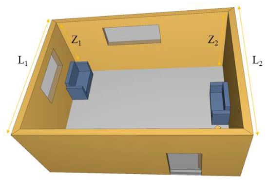
Figure 1.
Ventilation condition diagram of side-span room.
Wu [29] studied the location of different fire rooms in steel frame structures and the spatial temperature field distribution of different fire source locations in actual local fires in the room. Uniform fire is applied to the ground, and the temperature field distribution of the side-span room is shown in Figure 2.
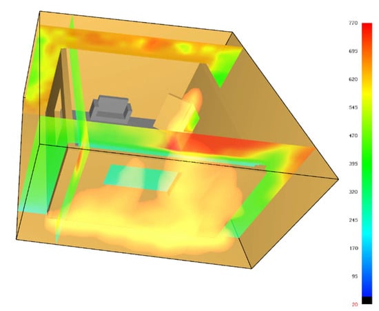
Figure 2.
Temperature field distribution of side-span room.
The temperature rise curve of beams and columns under uniform fire on the ground and the ISO 834 pair are shown in Figure 3:
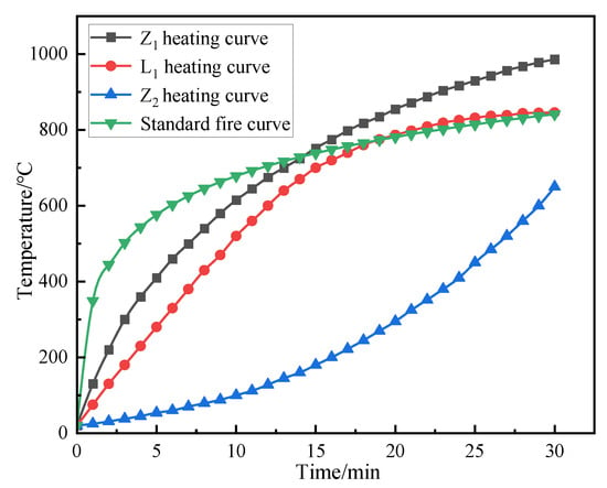
Figure 3.
Comparison of temperature rise curves of beam and column in side-span room under fire.
Under the condition of uniform fire in the side-span room, the temperature change in the fire beam column shows obvious stage characteristics. In the initial growth stage of the fire, the temperature of the beam and column near the window side changes slowly. Due to the gradual increase in the room temperature, the high-temperature air continuously dissipates heat due to better ventilation conditions in the process of flowing to the outside world, so that the initial temperature growth stage of the beam and column is slightly lower than the standard heating curve. This shows that in the early stage of fire, ventilation conditions have a certain buffer effect on heat loss, thus slowing down the temperature rise in beams and columns.
The above findings and mechanisms, especially the buffering effect of ventilation and the periodic temperature rise, are derived from the uniform fire scenario after a flashover. Although the specific temperature–time curve is unique to this configuration, its basic principle is that the ventilation conditions and the fire development stage significantly affect the thermal load of the structure. In the local fire scenario, the temperature distribution will be highly uneven, and the ventilation heat loss effect may be more significant for components far away from the fire plume. Therefore, the quantitative results proposed in this paper are directly applicable to the global analysis under uniform fire.
When the fire develops to a stable stage of full development, the situation changes significantly. At this stage, the indoor heat release rate increases significantly, and the fire intensifies, resulting in an accelerated oxygen consumption rate. However, enhanced ventilation conditions can provide a sufficient oxygen supply to support the continuous combustion of the fire. At this stage, the temperature rise curve of the column near the window shows a sharp upward trend, which is significantly higher than the standard temperature rise curve, and the maximum temperature difference is 251.86 °C. This indicates that in the full development stage of the fire, thanks to the ventilation conditions, the fire near the window is more vigorous, resulting in accelerated heat accumulation in the adjacent column and a sharp rise in temperature, far exceeding the standard temperature rise curve that characterizes the average fire development. In contrast, the direct thermal radiation intensity of the beam member is relatively weak due to it being relatively far away from the core area of the fire source. In the full development stage, the temperature rise curve of the beam is basically consistent with the standard temperature rise curve, indicating that the temperature evolution conforms to the typical fire development law, and there is no significant deviation.
For the columns and beams (L2, Z2) far away from the vent, due to the poor ventilation conditions, the heat is difficult to effectively dissipate, and the temperature rise curve is far lower than the standard temperature rise curve, and the maximum temperature difference is as high as 496.38 °C. This indicates that during the fire process, the temperature rise of the components far away from the vent is significantly inhibited due to the lack of sufficient oxygen supply and heat loss pathways, which is greatly deviated from the normal fire temperature development represented by the standard temperature rise curve. This further highlights the important influence of ventilation conditions on the temperature change of beams and columns during fire. The temperature changes of components at different positions show significant differences due to the different ventilation environments. The spatial heterogeneity of the temperature caused by ventilation differences seriously challenges the accuracy of simplified fire models that rely on the assumption of uniform temperature. This type of model will simultaneously underestimate the thermal invasion of near-opening components and overestimate the heating of components in poor ventilation areas, resulting in misjudgment of the risk of key parts and over-design of other areas. Therefore, the use of high-precision simulation tools that can restore the non-uniform thermal environment has become a necessary means for structural fire safety and reliability assessment.
The significant increase in the temperature of the column at the opening has an important influence on the fire resistance design of the structure. This indicates that the standard ISO 834 curve, which is the basis of the traditional fire rating, may seriously underestimate the thermal load of the key structural members located in the well-ventilated area during the fire period. This finding challenges the universal applicability of specification-based design methods and emphasizes the need for performance-based design methods. This method can take into account the effects of ventilation and real fire dynamics to ensure structural safety.
2.3. Steel Frame Mid-Span Fire Heating Conditions
When the mid-span of the steel frame is under fire, a low unilateral-ventilation window is set to simulate the ventilation conditions during the fire, and other conditions are the same as the fire conditions of the side-span. The room with the fire is shown in Figure 4:
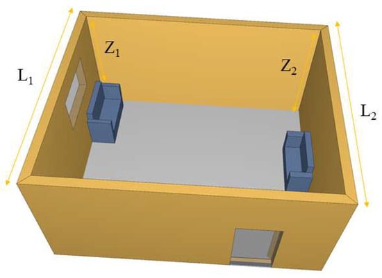
Figure 4.
Ventilation condition diagram of mid-span room.
The temperature rise curves of beams and columns under uniform fire and ISO 834 in mid-span room fires are shown in Figure 5:
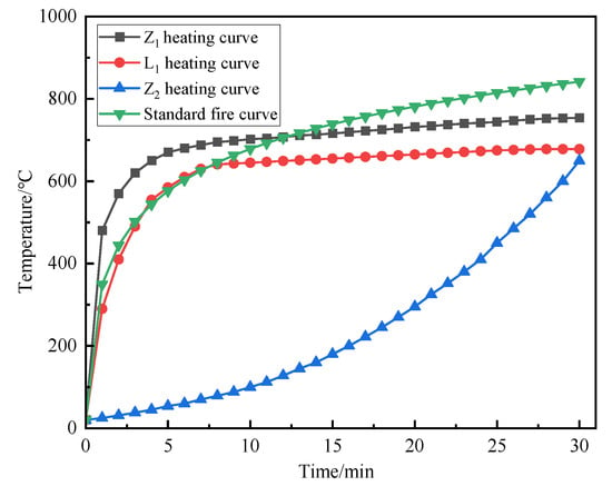
Figure 5.
Comparison of temperature rise curves of mid-span beams and columns under fire.
Under the condition of uniform fire in the mid-span room, the temperature change in the beam column shows different characteristics from that of the side-span room. In the initial growth stage of the fire, the temperature change trend in the beam and column near the side of the window is differentiated. Due to the gradual increase in the room temperature, with the ventilation conditions to the outside world being limited, the heat loss of high-temperature air out with the ventilation flow is greatly reduced. This leads to the temperature of the column in the initial growth stage being significantly higher than the standard heating curve, indicating that the column is heated more quickly in the initial stage of the fire, probably because the position of the column is closer to the fire source or the thermal radiation is more concentrated. The temperature rise curve of the beam is basically the same as the standard temperature rise curve, indicating that the temperature change in the beam in the initial stage is similar to the general fire development law, and there is no obvious lead or lag.
When the fire develops to a stable stage of full development, the indoor heat release rate increases significantly, the fire reaches its peak, and the oxygen consumption rate increases sharply. However, at this time, it is difficult for the ventilated low window set on one side to provide sufficient oxygen to maintain the further development of the fire, resulting in a limited oxygen supply. Under this condition, the temperature rise curve of beam and column members near the window area is significantly lower than the standard temperature rise curve, and the maximum temperature difference is 246.3 °C. This shows that in the full development stage, limited by the oxygen supply, the fire development near the window is inhibited, and the heat accumulation is slowed down, resulting in the temperature rise rate of the adjacent beams and columns being significantly lower than the standard temperature rise curve that characterizes the development of the normal fire temperature. For components away from the vent, the ventilation conditions are more unfavorable. The lack of oxygen supply is exacerbated, and heat is difficult to dissipate through effective convection. Therefore, the heating curve is much lower than the standard heating curve, and the maximum temperature difference is as high as 500.46 °C. This shows that during the fire process, the temperature rise in the components far away from the vent is significantly inhibited due to the serious lack of oxygen supply and effective heat dissipation channels, which is significantly deviated from the typical fire temperature development law represented by the standard heating curve. The results highlight the decisive influence of ventilation conditions on the temperature evolution of structural members in fire. The difference in the ventilation environment in the location of the components leads to significant spatial heterogeneity in temperature changes.
The Pyrosim model describes the different thermal behaviors in the initial stage of a fire and the heyday of a fire in more detail. This refined thermal boundary condition simulation provides a more realistic basis for subsequent mechanical analysis. By analyzing the degradation of mechanical properties of steel frames under this non-uniform fire, this study systematically quantified the critical failure threshold and accordingly proposed a more refined early warning threshold optimization model based on elastic modulus degradation. The model significantly improves the accuracy of the existing early warning methods and effectively reduces the actual prediction error of the project.
3. Fire Deformation Failure Analysis of Steel Frame
3.1. Introduction of Steel Frame Model
The ABAQUS sequential-thermal-coupling analysis module was used to simulate the collapse process of the steel frame structure. The thermal parameters are shown in Table 1: the unit type is a solid unit. In the sequential-thermal-coupling analysis, the temperature field is first analyzed by Pyrosim. The preset thermal boundary condition is that the convective heat transfer coefficient of the cylinder near the fire source is 1500, and the thermal radiation is 0.7. The convective heat transfer coefficient of the cylinder at the far fire source is 1100, and the thermal radiation is 0.5. The initial temperature of the model is 20 °C, and then the stress and displacement coupling analysis of the steel frame is carried out by adding a predefined temperature field. The overall size of the test steel frame is 18 × 10 × 15 m, the geometric size is shown in Figure 6, and the beam–column section size is shown in Table 2. The steel grade is Q235, and the initial stiffness is 206 GPa. In the static analysis of the steel frame structure, all beam–column joints are fixed, all column bases are rigid, and the influence of floor and wall is not considered. The frame does not consider the influence of the horizontal load, and the floor load is converted into the beam load for calculation. The standard value of beam dead load is 20 kN/m, and the standard value of the beam live load is 10 kN/m. The load combination was calculated by using ‘1.2 times dead load +0.5 times live load’ for collapse analysis. In this simulation, two simulated fire conditions were set up. The first case is that the first-floor side room is on fire, and the second case is that the first-floor middle room is on fire. The selected heating curve is the heating curve simulated by Pyrosim.

Table 1.
Steel thermal parameter local failure properties.
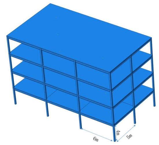
Figure 6.
Overall size diagram of steel frame.

Table 2.
Beam–column section size diagram.
3.2. Partial Lateral Collapse of Steel Frame
The parameters of the steel members that bear the load capacity are the deformation and deformation rate of beams and columns [14]. According to the specification ISO 834-1990 [28], the compression deformation and compression deformation rate of vertical load-bearing members are as follows:
In the formula, δ represents the axial deformation of the column; L is the calculation span of the specimen; H is the initial fire height before the temperature rise of the specimen; and T is the fire time/min.
The maximum deflection of the horizontal-load-bearing member beam is as follows:
The maximum deformation rate of beam deflection is as follows:
In the formula, δ is the deflection of the beam; L is the calculation span of the beam; H is the structural height of the beam section; and T is the fire time.
The parameters of steel frame members with large displacement under fire are shown in Figure 7:
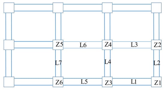
Figure 7.
Key component location diagram.
The distribution of the temperature transfer in the fire room is shown in Figure 8.
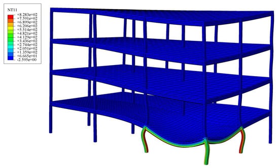
Figure 8.
Temperature field distribution of side-span under fire.
The temperature field distribution of the steel frame shows obvious regional differences. The external columns and beams L1, L2, Z1, Z2, and Z3 are exposed to the environment, the ventilation conditions are good, and the heat is dissipated faster through thermal convection and thermal radiation, resulting in higher temperatures. At the same time, the external structure has high thermal conductivity, a large exposed area, and high heat transfer efficiency, which further aggravates the temperature difference. In contrast, the internal components L3, L4, and Z4 are surrounded by other structures, and the ventilation conditions are insufficient. The heat is difficult to dissipate through heat convection and mainly depends on heat conduction. However, due to the high ambient temperature, the heat dissipation efficiency is low, resulting in a lower temperature. This significant non-uniformity of the temperature distribution produces a serious thermal gradient, and the measured temperature difference between the columns is as high as 485 °C. The measured temperature difference between the beam components is as high as 220 °C. The external components (Z1, Z2, Z3) near the ventilation opening reached a critical temperature of more than 780 °C in 32 min, resulting in a rapid decrease in strength and stiffness. On the contrary, the internal member (Z4) is kept below 300 °C due to the avoidance of direct cooling and heating effects, thereby maintaining its structural integrity and carrying capacity at room temperature. This imbalance greatly changes the force transmission path of the structure and accelerates the collapse mechanism. The overall displacement diagram of the steel frame with a fire-damaged side-span is shown in Figure 9:
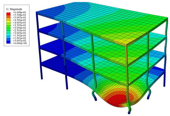
Figure 9.
Overall displacement diagram of side-span steel frame under fire.
When the axial displacement and displacement rate of the column reach the following values, it is proved that the fire column member loses its bearing capacity.
The displacement is positive upwards and negative downwards. The axial displacement of different fire columns is shown in Figure 10:
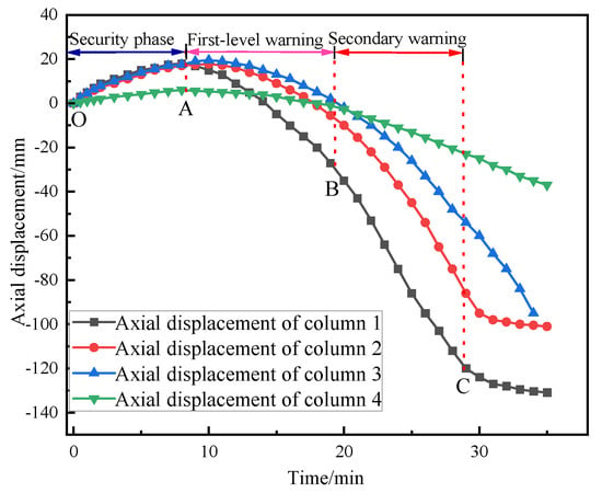
Figure 10.
Axial displacement diagram of different fire columns.
Through the analysis of the data in the diagram, it can be concluded that the thermal expansion effect of Z1, Z2, and Z3 is significant, while the thermal expansion effect of Z4 is weak, which is mainly due to the live load in the middle of the steel frame. To a certain extent, this offsets the thermal expansion effect of Z4. A, B and C represent the critical points of three-level early warning respectively. Warning point A marks the end stage of thermal expansion. At the initial stage of the fire, the axial deformation rate of each column is maintained at about 1.5 mm/min. At warning point B, the axial deformation rates of Z1, Z2, Z3, and Z4 were 6 mm/min, 5.6 mm/min, 5 mm/min, and 3 mm/min, respectively, which did not reach the limit value. At early warning point C, the axial deformation rates of Z1, Z2, and Z3 reached 15.2 mm/min, 13.6 mm/min, and 12.4 mm/min, respectively, which exceeded the limit value and lost the bearing capacity, while the axial deformation rate of Z4 was 5.6 mm/min, which did not reach the limit value and still had a certain bearing capacity. The axial force changes of different fire columns are shown in Figure 11:
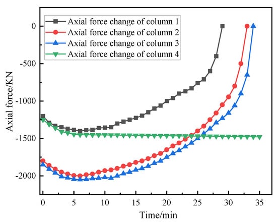
Figure 11.
Axial force changes of different fire columns.
The fire test data show that the axial force evolution and failure mode of the structural column are significantly affected by the ventilation conditions of its location: the axial forces of Z1, Z2, and Z3 columns show a typical degradation path of transient increase first, then continuous decrease, and finally a sharp loss within about 30 min, which marks the rapid failure of the bearing capacity; in contrast, the axial force of the Z4 column with limited ventilation changes gently and tends to be stable only after a short increase in the initial stage, so that it still maintains an effective bearing capacity at 30 min. In addition, Z5 and Z6 columns show gentle displacement development and ductile failure characteristics, while the side-span columns are subjected to severe asymmetric heating due to good ventilation on three sides of the fire, which leads to bending and torsion instability, while the mid-span columns are more prone to sudden axial compression instability due to slow heating due to less ventilation difference on the fire surface. The fire resistance limits of different fire columns are shown in Table 3:

Table 3.
Fire resistance limit of different fire columns under side-span fire.
When the deflection displacement and the displacement rate of the beam reach the following values, respectively, it shows that the beam is close to the ultimate bearing capacity.
The mid-span deflections of different fire beams are shown in Figure 12:
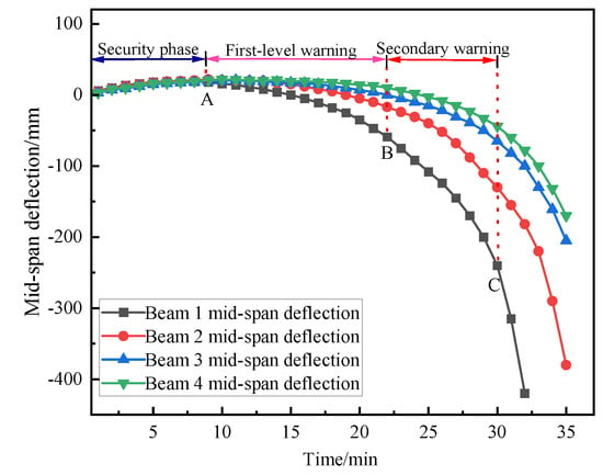
Figure 12.
Mid-span deflection curves of different fire beams.
Through the analysis of the data in the figure, it can be concluded that the beam is basically consistent in the thermal expansion stage, and early warning point A is the end stage of thermal expansion; warning point B is that the deflection value of the beam is greater than 100 mm or the deflection rate of the beam is greater than 30 mm/min, and the secondary collapse warning is issued; warning point C is that the deflection of the beam is greater than 300 mm or the deflection rate of the beam exceeds 87.2 mm/min, and a three-level warning is issued. L1 and L2 exceeded the limit value and lost their bearing capacity at 30 min and 33 min, respectively. L3 and L4 did not exceed the limit value and could continue to carry the load. The fire resistance limits of different fire beams are shown in Table 4:

Table 4.
Fire resistance limit of different fire beams.
When the bearing capacity of the Z1, Z2, and Z3 columns and the L1 and L2 beams degrades under a sustained load for about 30 min, the high-temperature creep effect of steel and the deterioration of section stiffness jointly cause the buckling instability of members, resulting in the change of the original load path and triggering the redistribution of internal forces, which eventually leads to the local lateral collapse of the steel frame.
The local lateral collapse of the steel frame is mainly realized as a ductile failure, which is mainly due to the combined effect of its constraint conditions, deformation capacity, and load transfer path. The side-span is usually less constrained, allowing thermal expansion deformation to release part of the thermal stress and reducing the accumulation of internal stress. The softening and ductility improvement of steel at high temperatures promote the local formation of plastic hinges and continuous energy consumption through plastic deformation; at the same time, the load after the failure of the side-span can be redistributed through the redundant paths of the adjacent spans, delaying the overall instability process, thus showing the progressive ductile collapse characteristics. This ductile and progressive failure mechanism is critical to life safety. It provides a critical time buffer after the initial failure occurs, significantly extending the time window for evacuation and emergency intervention from the trigger warning to the final loss of structural stability.
3.3. The Steel Frame Collapses Inward as a Whole
The temperature distribution of the fire room under the second working condition is shown in Figure 13.
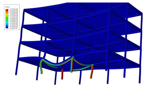
Figure 13.
Temperature field distribution of mid-span under fire.
It can be seen from Figure 13 that there are significant differences in the response characteristics of the side-span and the mid-span of the steel frame under fire:
Side-span column: Due to the fire on three sides and good ventilation conditions, the cross section of the column forms a severe unilateral temperature gradient in a short time, and the inner temperature is as high as 700–800 °C, resulting in a fast heating rate. This non-uniform heating mainly causes the asymmetric bending deformation of the cylinder with the risk of torsional instability. Therefore, the horizontal displacement of the top of the column should be monitored.
Mid-span column: The fire surface is less and the ventilation is limited. The temperature distribution is relatively symmetrical, but the heating rate is slow. Under this condition, the steel column is more prone to axial compression instability dominated by axial compression. It is necessary to focus on monitoring the vertical displacement of the column top and the horizontal displacement of the mid-span. Such instability often has sudden characteristics. The failure mechanism caused by the ventilation difference requires a targeted design response: the side-span column needs to strengthen fire protection or adopt a box section with stronger torsion resistance to prevent torsional buckling; the mid-span column should control the axial compression ratio and ensure redundant load paths, such as catenary force, to prevent axial instability. This conclusion highlights the value of performance-based fire protection design.
The stress cloud diagram of each component after 40 min of fire combustion is shown in Figure 14:
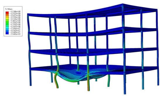
Figure 14.
Mises cloud map of the mid-span room.
According to the analysis of the stress cloud diagram, the mechanical properties of steel under fire are significantly degraded. As the temperature increases, the elastic modulus of the steel column and the steel beam decreases significantly. The yield strength of the fire component decreases significantly after 40 min of combustion, and the column enters the plastic state and yields as a whole. Under the action of an eccentric load, there is a large deflection in the mid-span of the column and the mid-span of the beam, and a significant displacement occurs at the top of the fire column, and the axial force also plummets. The adjacent members of the fire room do not reach the yield strength and can still bear the load normally. As the bearing capacity of the fire column continues to decline, the internal force redistribution effect causes the stress of the upper column to increase, and the stress of the beam end flange connected to the steel column also increases. The yield development process under different collapse modes is significantly different. The local lateral collapse starts from the asymmetric yielding of the beam–column assembly, forming a plastic hinge that leads to the lateral displacement mechanism. The overall inward collapse is driven by the symmetrical axial yield of multiple columns, which eventually leads to the general loss of vertical support. The key point is that the two failure sequences are consistent with the severe stress concentration at the beam end connection as the precursor, which indicates the activation of catenary action and is a universal signal for predicting collapse. The overall displacement diagram of the mid-span steel frame under fire is shown in Figure 15:
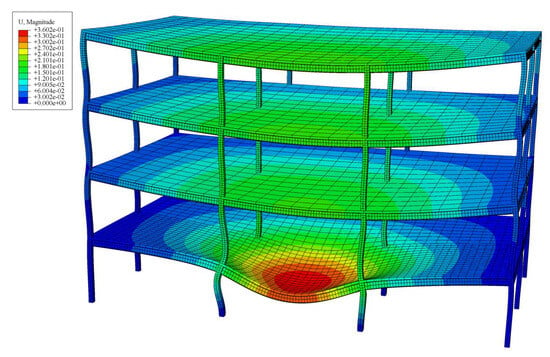
Figure 15.
Overall displacement diagram of mid-span steel frame under fire.
The axial displacement of different fire columns is shown in Figure 16:
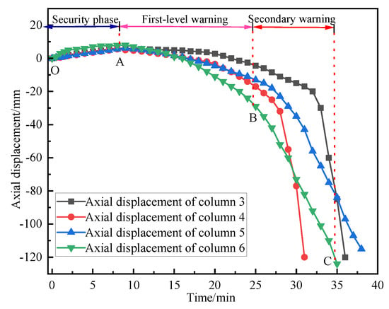
Figure 16.
Axial displacement diagram of mid-span fire column.
It can be seen from the diagram that the expansion of the column under the condition of mid-span fire is reduced. First-order warning point A marks the end of the free thermal expansion stage and represents the maximum expansion point with a net deformation rate of zero. Subsequently, the development of the binding force begins to dominate. At the initial stage of the fire, due to uniform heating and expansion, the axial deformation rate of each column is generally maintained at about 1 mm/min. At secondary warning point B, the axial deformation rates of Z3, Z4, Z5, and Z6 are 5 mm/min, 5.8 mm/min, 5.6 mm/min, and 6 mm/min, respectively. The critical limit value and the limit rate defined for structural collapse have not yet been reached. This stage marks the transition from pure thermal expansion to significant compressive stress development. As the columns expand axially, they are increasingly constrained by the colder, more rigid parts of the surrounding structure. This constraint converts thermal expansion into compressive stress in the heating column. The transition to the local damage warning level at point C is characterized by significant differentiation of behavior. The deformation rate of the Z3 and Z4 columns increased sharply to 32 mm/min and 38 mm/min, respectively, indicating that they completely lost their bearing capacity. The physical mechanism of this rapid failure is a chain reaction triggered by stress concentration and thermal softening. The bottom areas of Z3 and Z4 are identified as high-stress concentration areas. With the increase in temperature, the yield strength and elastic modulus of steel deteriorate significantly. The initially developed compressive stress eventually exceeds the yield strength of the material due to the high temperature, causing local plastic yield. This yield leads to a catastrophic loss of stiffness in the affected area, effectively forming a plastic hinge. The structure then undergoes rapid stress redistribution, transferring the additional load to the already-damaged section. This process accelerates the plastic flow, resulting in an exponential increase in the observed displacement rate without significant additional plastic deformation, which is a sign of quasi-brittle failure at high temperatures. The decrease in material ductility and the lack of rotational capacity at the support in the high-temperature environment further aggravate this process, prevent the ductility behavior, and lead to sudden failure. In contrast, the deformation rates at warning point C of Z5 and Z6 are 13.4 mm/min and 12.6 mm/min, respectively. It is because these columns are less constrained or the temperature is slightly lower, delaying the triggering of the same failure mechanism.
The maximum horizontal displacement of different fire columns in the mid-span of the fire is shown in Figure 17:
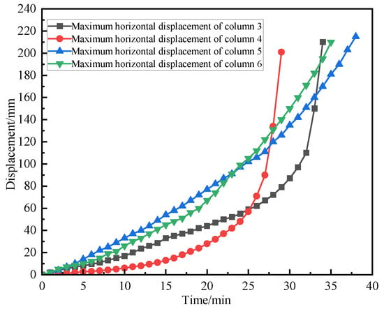
Figure 17.
The maximum horizontal displacement diagram of the mid-span fire column.
According to specification ISO 834-1 [28], the maximum allowable horizontal displacement of the steel frame structure is H/25, which is 160 mm. Through careful analysis of the graphic data, for Z3 and Z4, the deformation rate of horizontal displacement is relatively low in the early stage of fire. The displacement rate of Z3 maintains a relatively stable and slow growth trend in the first 33 min after the fire, while Z4 shows similar low-rate deformation characteristics in the first 27 min. When the above time points are reached, the deformation rate of the two columns rises sharply, the displacement curve rises steeply, and the maximum deformation threshold is quickly reached, resulting in the failure of the components. This failure mode shows typical brittle failure characteristics and lacks obvious plastic deformation stage, indicating that it bears stress exceeding its own bearing capacity in a short period of time, thus causing sudden instability failure.
Compared with the Z3 and Z4 columns, the horizontal displacement development rate of the Z5 and Z6 columns is relatively flat. During the whole fire process, the displacement–time curve of the two columns showed a relatively stable growth trend. When the fire lasts for about 35 min, the displacement value approaches the limit state. This response characteristic presents a typical ductile failure mode, which shows that the component undergoes a significant plastic deformation stage before reaching the ultimate displacement, reflecting its good energy dissipation capacity and continuous deformation capacity under high temperature. The fire resistance limits of different fire columns are shown in Table 5:

Table 5.
Fire resistance limit of different fire columns under mid-span fire.
The mid-span deflection of different beams under fire in the mid-span is shown in Figure 18:
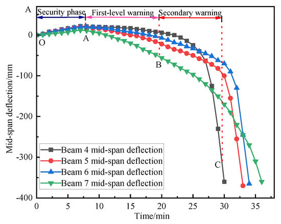
Figure 18.
Mid-span deflection diagrams of different fire beams.
Through the analysis of the data in the figure, it can be concluded that the beam is basically consistent in the thermal expansion stage, and early warning point A is the end stage of thermal expansion; at warning point B, the deflection rates of L4, L5, L6, and L7 are 9 mm/min, 10 mm/min, 10.5 mm/min, and 11.5 mm/min, respectively, and the secondary collapse warning is issued. At warning point C, the deflection rates of L4, L5, L6, and L7 are 145 mm/min, 95.4 mm/min, 57.8 mm/min, and 68 mm/min, respectively, and a three-level collapse warning is issued. L4 and L5 exceeded the limit value and lost their bearing capacity at 29 min. Although L6 and L7 did not exceed the limit rate value at 30 min, they could not continue to bear the load due to the lack of obvious plasticity in the fire damage of the mid-span. The fire resistance limits of different fire beams are shown in Table 6:

Table 6.
Fire resistance limit of different fire beams under mid-span fire.
The brittle failure of the mid-span is determined mainly from the energy ratio and the brittleness index, IB. The plastic energy dissipation, E, of L6 and L7 is calculated according to the plastic hinge of the whole section:
In the formula, E0 is the total energy dissipated by the plastic rotation of the beam after the plastic hinge is formed in the mid-span, Mpl is the full-section plastic bending moment, θpl is the ultimate rotation angle of the plastic hinge, and L is the length of the plastic hinge section and takes the span of the beam.
The calculation is based on the following assumptions: (1) The plastic hinge is formed at the beam end and reaches the plastic state of the whole section. (2) The length of the plastic hinge region is taken as the span of the member, which is a simplified macroscopic treatment method to characterize the overall energy dissipation capacity of the entire plastic zone. (3) The ultimate plastic rotation angle θpl is 0.03 rad, which refers to the common value range in the study of fire resistance and progressive collapse resistance of steel structures in European codes, and reflects the typical ductility of steel under high temperatures and large deformation.
The potential energy released by the overall collapse of the mid-span is as follows:
E0/E = 29.8%, which is much lower than the ductile collapse threshold of 70%, indicating that the energy is mainly released by the overall instability at one time, rather than the continuous energy consumption of the beam. It is manifested as a brittle failure.
The brittleness index, IB:
In the formula, ∆δmax is the maximum deflection value monitored, Δt is the time that the displacement falls from the peak to the residual value, Fpeak is the peak bearing capacity, and Fdrop is the loss of bearing capacity in the same time period.
When the side-span is under fire,
When caught in the middle of a fire,
The brittleness index of the side-span under fire is much smaller than that of the mid-span under fire, so the side-span under fire presents a ductile failure, and the mid-span under fire presents a brittle failure.
The main reason for the absence of an obvious plastic failure of the structure under the fire condition of the mid-span can be attributed to the combined action of the constraint effect, the sensitivity of the force transmission path, and the instability mechanism: the mid-span is limited by the strong constraint of the surrounding structure, and the thermal expansion deformation cannot be fully released, resulting in a sharp increase in compressive stress at high temperatures and the superposition of the live load, causing stress concentration; at the same time, as a key force transmission hub, the failure of the mid-span directly cuts off the load redistribution path, with low redundancy, and the compressive members after high-temperature softening are prone to sudden buckling instability. In order to quantify the redundancy of adjacent spans, the load redistribution is analyzed from the axial force migration ratio. The axial force transfer ratio is defined as follows:
RAF is the axial force transfer ratio, ΔN is the axial force increment of adjacent columns, and N is the original axial force of the failed column.
From Figure 11, the original axial force of column 1 is 1100 KN, the axial force after failure is 0, and the new axial force of adjacent columns is as follows: the axial force increment (peak-initial value) of column 2 after the fire is 650 KN, the axial force migration ratio is 59%, and column 2 shares 59% of the original load of failure column 1; the axial force increment of column 3 after the fire is 750 KN, the axial force migration ratio is 68.2%, and column 3 shares 68.2% of the original load of failure column 1; the axial force increment of column 4 after the fire is 260 KN, the axial force migration ratio is 23.6%, and column 4 shares 23.6% of the original load of failure column 1. Because the load redistribution of column 4 is less, column 4 is not damaged. The path of load redistribution is mainly manifested as the load redistribution of adjacent members—column 2, column 3, and column 4—after the failure of column 1. It shows that the adjacent columns are significantly overloaded, which verifies the intensity of load redistribution under the redundancy mechanism. Finally, the local instability triggers the chain collapse of the whole structure, which is manifested as the collapse failure without obvious plastic deformation.
4. Determination of Early Warning Threshold of Acoustic Emission Parameters
The method of new early warning technology based on acoustic emission is to determine the change of elastic modulus of steel by using the change in the transverse and longitudinal wave velocity of steel at high temperature. The theoretical formula is as follows:
In the formula, ρ is the steel density, Cs is the shear wave velocity, and T is the ratio of the longitudinal wave velocity to the shear wave velocity.
Xie [27] described the parametric response of steel acoustic emission at high temperatures in detail and verified the theoretical formulas of the elastic modulus and the transverse and longitudinal wave velocities. Yang [30] describes the transverse and longitudinal wave velocity conversion and propagation path of steel, as shown in Figure 19:

Figure 19.
Acoustic emission transverse and longitudinal wave velocity propagation path.
The thickness of component d is 8 mm; the transverse waves are T1, T2, and T3; the longitudinal waves are L1, L2, and L3; W is a converted echo; and α is the angle between the transverse wave velocity and the longitudinal wave velocity. The unidirectional propagation time of the transverse wave is tT, and the unidirectional propagation time of the longitudinal wave is tL. T1, T2, and T3 are the first, second, and third echoes of the transverse wave [31], so tT1 = 2 × tT, tT2 = 4 × tT, and tT3 = 6 × tT. L1, L2, and L3 are the first, second, and third echoes of the longitudinal wave, so TL1 = 2 × tL, TL2 = 4 × tL, and TL3 = 6 × tL. W1 and W2, therefore, are tW1 = tT + tL and tW2 = 2tT + 2tL.
The three-level early warning elastic modulus threshold of the fire column under the overall inward collapse mode of the steel frame is known. The three-level early warning transverse and longitudinal wave velocity parameters based on acoustic emission are shown in Table 7, Table 8 and Table 9:

Table 7.
Acoustic emission parameters under first-level warning.

Table 8.
Acoustic emission parameters under second-level warning.

Table 9.
Acoustic emission parameters under third-level warning.
Based on acoustic emission technology, the block diagram of the new early warning method is shown in Figure 20.

Figure 20.
New warning method block diagram of acoustic emission transverse and longitudinal wave velocity.
5. Conclusions
Based on a sequential thermo-mechanical coupling numerical simulation, this paper deeply studies the collapse mechanism of and an early warning method for a steel frame under fire. The core innovation is to establish a set of quantitative early warning threshold systems from structural instability mechanical responses to material acoustic performance parameters, which lays a solid theoretical foundation for real-time collapse warning for steel structure fires based on the acoustic emission wave velocity. The main innovative conclusions are as follows:
(1) Refined modeling and revealing of fire temperature rise characteristics: Pyrosim software is used to simulate the non-uniform temperature field at different positions of steel frame members in real fire scenarios, which breaks through the limitations of standard temperature rise curves. The results show that the heating process of the component is significantly affected by the fire location and ventilation conditions. The refined modeling provides the key input for the accurate simulation of the subsequent structural response and the determination of the critical threshold. At present, this study only considers the working conditions under a specific fire source location and opening rate. Future work will include a systematic parametric analysis of the opening rate and the fire source location to more fully reveal their influences. In practical applications, engineers can integrate this CFD-based simulation workflow into performance-based design projects, especially for complex or important buildings where conventional methods are not applicable, to obtain a more realistic assessment of structural behavior in fires.
(2) The mechanism of different collapse modes and the three-stage elastic modulus early warning threshold system based on instability criterion are as follows: By simulating the response of the structure under the fire temperature field, the criterion of the critical point of structural instability is proposed and applied based on the displacement of the key nodes of the beams and columns and the mutation characteristics of the change rate. The three-level early warning elastic modulus thresholds of the fire beam and the fire column under two typical collapse modes are systematically and quantitatively determined. The early warning thresholds of the local lateral collapse fire beam are 141.2 GPa, 77.8 GPa, and 53.68 GPa, and the early warning thresholds of the fire column are 164.5 GPa, 117.5 GPa, and 58.75 GPa. The early warning thresholds of the overall inward collapse of the fire beam are 153.6 GPa, 78.6 GPa, and 57.5 GPa, and the early warning thresholds of the fire column are 168.7 GPa, 122.4 GPa, and 72.6 GPa. The overall inward collapse limits thermal expansion due to strong constraints, resulting in a sharp increase and concentration of stress, and the damage is more sudden. The warning threshold is relatively higher, and the risk of collapse is greater, which highlights the importance of setting a threshold based on a specific mode.
(3) This study pioneered the establishment of a quantitative correlation model between the elastic modulus threshold of steel structures under fire and the propagation characteristics of ultrasonic transverse and longitudinal wave velocities. For the first time, the three-level warning thresholds of transverse and longitudinal wave velocities for the overall inward collapse of the fire column is derived and provided: the three-level warning thresholds of the shear wave velocity are 2843 m/s, 2422 m/s, and 1865 m/s. The third-level warning thresholds of the longitudinal wave velocity are 5771 m/s, 4917 m/s, and 3786 m/s. An accurately quantified wave velocity threshold is the core input parameter for an early collapse warning system for high-temperature steel structures based on the acoustic emission signal. For the first time, this study provides a direct, reliable theoretical basis and key setting values for the development of such real-time monitoring and early warning technology for specific failure modes and realizes a major leap from mechanical mechanism research to an engineering application interface.
Author Contributions
Conceptualization, F.X.; Methodology, M.X. (Ming Xie); Software, X.W.; Validation, X.W.; Investigation, F.X. and Z.W.; Data curation, L.Y., M.X. (Mengqi Xu) and X.L.; Writing—original draft, F.X.; Writing—review & editing, F.X.; Visualization, Z.W.; Supervision, L.Y. and X.L.; Project administration, M.X. (Mengqi Xu). All authors have read and agreed to the published version of the manuscript.
Funding
Research on building intelligent early warning and self-centering system for landslide disaster, Open Fund of National Civil Engineering Structure Prefabrication and Assembly Engineering Technology Research Center (2023CPCCE-K05); National Natural Science Foundation of China, General Project, Open-pit Slope Stability Prediction under the Interaction of Blasting and Rainfall (51874268).
Data Availability Statement
The original contributions presented in this study are included in the article. Further inquiries can be directed to the corresponding author.
Conflicts of Interest
The authors declare no conflict of interest.
References
- Sun, R.; Huang, Z.; Burgess, I.W. Progressive collapse analysis of steel structures under fire conditions. Eng. Struct. 2012, 34, 400–413. [Google Scholar] [CrossRef]
- Jiang, B.; Li, G.Q.; Usmani, A. Progressive collapse mechanisms investigation of planar steel moment frames under localized fire. J. Constr. Steel Res. 2015, 115, 160–168. [Google Scholar] [CrossRef]
- Jiang, J.; Usmani, A. Modeling of steel frame structures in fire using OpenSees. Comput. Struct. 2013, 118, 90–99. [Google Scholar] [CrossRef]
- Jiang, J.; Jiang, L.; Kotsovinos, P. OpenSees software architecture for the analysis of structures in fire. J. Comput. Civ. Eng. 2015, 29, 04014030. [Google Scholar] [CrossRef]
- Memari, M.; Wang, X.; Mahmoud, H. Hybrid simulation of small-scale steel braced frame subjected to fire and fire following earthquake. J. Struct. Eng. 2020, 146, 04019182. [Google Scholar] [CrossRef]
- Zhao, J.C.; Shen, Z.Y.; Shen, W.P. Experimental research on fire resistance of steel frames. Civ. Eng. J. 1997, 02, 49–55. [Google Scholar]
- Li, G.Q.; Jiang, S.C. Prediction to nonlinear behavior of steel frames subjected to fire. Fire Saf. J. 1999, 32, 347–368. [Google Scholar] [CrossRef]
- Wang, X.; Kim, R.E.; Kwon, O.S. Hybrid simulation method for a structure subjected to fire and its application to a steel frame. J. Struct. Eng. 2018, 144, 04018118. [Google Scholar] [CrossRef]
- Qin, C.; Mahmoud, H. Collapse performance of composite steel frames under fire. Eng. Struct. 2019, 183, 662–676. [Google Scholar] [CrossRef]
- Ju, Z.; Wang, Z.Q.; Han, Y.L. Structure collapse analysis of steel frame under fire condition. Eng. Mech. 2014, 31, 121–124. [Google Scholar]
- Shakil, S.; Lu, W.; Puttonen, J. Response of high-strength steel beam and single-storey frame in fire. Numer. Simul. J. Constr. Steel Res. 2018, 148, 551–561. [Google Scholar] [CrossRef]
- Franssen, J.M.; Cooke, G.M.; Latham, D.J. Numerical simulation of a full scale fire test on a loaded steel framework. J. Constr. Steel Res. 1995, 35, 377–408. [Google Scholar] [CrossRef]
- Jiang, J.; Li, G.Q. Disproportionate collapse of 3D steel-framed structures exposed to various compartment fires. J. Constr. Steel Res. 2017, 138, 594–607. [Google Scholar] [CrossRef]
- Lyu, B.L. Case of Fire Resistance to Progressive Collapse of Steel Frame Performance Analysis. Master’s Thesis, South China University of Technology, Guangzhou, China, 2014. [Google Scholar]
- Gao, Y.C. The Failure Analysis of Space Steel Frame Structure in Fire. Master’s Thesis, Hebei University of Technology, Tianjin, China, 2018. [Google Scholar]
- Jiang, J.; Li, G.Q.; Usmani, A. Progressive collapse analysis of steel structures in fire using opensees. J. Disaster Prev. Mitig. Eng. 2015, 35, 1–5. [Google Scholar]
- Ren, W.; Zhao, J.C. Collapse analysis on steel frame structure under compartment fire based on sub-structure model. J. Southeast Univ. 2021, 51, 312–317. [Google Scholar]
- Wu, P.; Zong, J.H. Collapse mechanism analysis of steel frame structure based on actual fire scene. Fire Sci. Technol. 2020, 39, 351–357. [Google Scholar]
- Duan, J.Q.; Yang, D.L.; Liu, X.C. Seismic energy dissipation and hysteresis performances of distinctly shaped steel-reinforced concrete column-beam joints under cyclic loading. Buildings 2024, 14, 2777. [Google Scholar] [CrossRef]
- Bai, B.; Wang, Y.Y. Practical checking method for fire resistance of reinforced bottom frame of masonry buildings. Fire Sci. Technol. 2016, 35, 304–307. [Google Scholar]
- Li, G.Q.; Feng, C.Y.; Lou, G.B. Easy-measured key parameters and early-warning methods for the collapse prediction of steel portal frames under fire. China Civ. Eng. J. 2021, 54, 62–75. [Google Scholar] [CrossRef]
- Lyu, J.L. Study on Fire Resistance of Beam and Column in the Overall Steel Frame. Master’s Thesis, Harbin Institute of Technology, Harbin, China, 2013. [Google Scholar]
- Wang, Y.; Liu, N.X. Stress measurement of steel members based on ultrasonic amplitude spectrum considering temperature effect. Non-Destr. Insp. 2022, 44, 12–17. [Google Scholar]
- Men, P.; Dong, S.Y.; Yan, S.X. Influence of heat treatment and measurement methods on material hardness evaluation by longitudinal wave velocity. J. Beijing Univ. Aeronaut. Astronaut. 2018, 44, 2312–2320. [Google Scholar]
- Lyu, G.L.; Wang, B.X. Ultrasonic wave velocity and hysteresis in hot steel. Acta Acust. 1992, 6, 446–450. [Google Scholar]
- He, Y.M.; Chen, Y.M. Experimental study on ultrasonic surface wave detection of surface stress of metal materials. J. Exp. Mech. 2006, 05, 601–606. [Google Scholar]
- Xie, M.; Xu, F.B. Investigating fire collapse early warning systems for portal frames. Buildings 2025, 15, 296. [Google Scholar] [CrossRef]
- ISO 834-1990; Fire-Resistance Tests-Elements of Building Construction-Part 1: General Requirements. ISO: Geneva, Switzerland, 2014.
- Wu, P. Analysis of Temperature Field and Mechanical Properties of Steel Frame Based on Actual Fire. Master’s Thesis, Hebei University of Technology, Tianjin, China, 2016. [Google Scholar]
- Yang, H.N. Measurement of elastic modulus of solid materials based on ultrasonic late echo. J. Data Acquis. Process. 2020, 4, 16. [Google Scholar]
- Zhao, J.H. Test of constants and ultrasonic wave mode conversion of isotropic metals by EMAT. Non-Destruct. Insp. 2018, 40, 21–24. [Google Scholar]
Disclaimer/Publisher’s Note: The statements, opinions and data contained in all publications are solely those of the individual author(s) and contributor(s) and not of MDPI and/or the editor(s). MDPI and/or the editor(s) disclaim responsibility for any injury to people or property resulting from any ideas, methods, instructions or products referred to in the content. |
© 2025 by the authors. Licensee MDPI, Basel, Switzerland. This article is an open access article distributed under the terms and conditions of the Creative Commons Attribution (CC BY) license (https://creativecommons.org/licenses/by/4.0/).