Abstract
To effectively improve the anti-progressive collapse performance of steel frames, a novel reinforced joint, named the welded steel-frame joints strengthened by outer corrugated plates, was proposed. Firstly, the finite element model was validated according to previous test results. The anti-progressive collapse behavior of the novel reinforced joint was analyzed based on the validated modeling method. Effects of the central angle, corrugated plate thickness, corrugated plate width, length of circular arc, and welding angle on the anti-progressive collapse behavior of the reinforced joint were discussed. The design suggestions of the corrugated plates are presented. Finally, the effectiveness of the outer corrugated plates was further verified through one full-scale beam–column joint case and three plane frames. The results show that compared with the specimen strengthened by inner corrugated plates, the peak load and ultimate displacement of the joint strengthened by outer corrugated plates increased by 17.0% and 16.3%, respectively. Compared with the traditional full-scale beam–column joint, the load-bearing capacity and ultimate displacement of the joint strengthened by outer corrugated plates designed under reasonable suggestions significantly increased. Simply from the perspective of joints, the design suggestions were highly effective. Compared with the traditional plane steel-frame case with a total height of six floors, the bearing capacity and ultimate displacement of the plane steel-frame case strengthened by outer corrugated plates increased by 19.8% and 38.3%, respectively. The outer corrugated plates demonstrated a more pronounced effect in enhancing the collapse resistance for middle floors. Overall, the novel type of joint had a simple form and clear mechanical principles, which fully exerted the catenary capacity of the steel beams. The outer corrugated plates significantly improved the anti-progressive collapse performance of steel-frame structures.
1. Introduction
Progressive collapse constitutes a cascading failure process initiated by localized structural damage under accidental loads, potentially leading to catastrophic consequences. The frequent occurrence of such collapses in building structures has garnered significant attention from researchers and engineering practitioners [1,2]. In addition to conducting collapse analysis [3,4,5], improving the anti-collapse behavior of structures through various measures has become an effective way to prevent this type of accidents [6,7,8].
Beam–column joints are critical components of steel frame structures. Their performance—including strength, stiffness, rotational capacity, and energy dissipation capability—significantly impacts the overall stiffness, load bearing capacity, and collapse resistance of the structural system. Current research shows that the failure of steel-frame structures is often concentrated at beam–column joints under large deformation conditions after column loss [9]. Especially for welded joints, once a fracture occurs, the joint will be destroyed, and the structure will quickly collapse. Therefore, enhancing the progressive collapse resistance of steel beam–column joints represents a critical engineering imperative.
To enhance connection robustness in steel structures, researchers have proposed various novel joint configurations [10]. Wang et al. [11] developed a reinforced joint by incorporating folded plates at beam–column connections. Their results demonstrated that these plates significantly enhanced both the load-bearing capacity and ductility of conventional steel-frame joints. Similarly, welding corrugated plates at the same location has been shown to improve progressive collapse resistance in steel-frame structures [12]. Alembagheri et al. [13] examined the key factors influencing strengthening strategies for modular steel frames and proposed techniques to mitigate progressive collapse. Zhang et al. [14] enhanced the robustness of steel frames under column loss scenarios by installing seat angles and steel plates with long-slotted holes. Qin et al. [15] presented a beam-to-tubular column connection designed for progressive collapse prevention. Their results demonstrated that the reinforced welded flange-bolted web connection effectively facilitated catenary action in the beams. Han et al. [16] analyzed the effectiveness of joints with cast stiffeners in preventing the progressive collapse of steel frames, and developed corresponding microscopic models. Meng et al. [17] developed a reinforced extended end-plate connection by incorporating bending stiffened plates within the connection region. Qiao et al. [18] devised a novel joint incorporating kinked bars at the beam–column interface to establish a backup load path. Additionally, Kiakojouri et al. [19] provided a review of retrofitting techniques for progressive collapse mitigation, including joint enhancement measures for steel frames. Wei et al. [20] investigated a double-hinge steel frame joint featuring a replaceable T-shaped energy dissipator, verifying its superior collapse resistance compared to traditional welded joints.
Each of the above joints has its own advantages, indicating that improving the connection details is of great benefit in enhancing the resistance to progressive collapse of steel-frame structures. However, the existing achievements have certain shortcomings in improving both bearing capacity and ductility, and the form is relatively complex. In fact, a reasonable reinforcement method for steel-frame joints should not only have good mechanical properties, but also be easy to construct.
Therefore, to enhance the bearing capacity and ductility of traditional steel-frame joints while considering construction efficiency, this study introduced welded steel-frame joints strengthened by outer corrugated plates (WSOC). These joints were fabricated by welding outer corrugated plates within the beam–column joint region. A finite element (FE) model was validated using previous experimental results. Using this validated modeling approach, the progressive collapse resistance of the WSOC joints was analyzed. The effects of key geometric parameters—including central angle, corrugated plate thickness, corrugated plate width, circular arc length, and weld angle—on the progressive collapse resistance were systematically investigated. Design suggestions of the corrugated plates were then proposed. Finally, the effectiveness of the outer corrugated plates was further verified through one full-scale beam–column joint case and three plane frames.
2. Proposal of a Novel Type of Joint
Fully welded joints can reduce the amount of steel used, improve the stability and strength of steel frames, and are a commonly used method of connecting steel structures. However, under progressive collapse conditions, stress concentrations at the beam–column connection or weld failures can cause premature loss of bearing capacity and excessive deformation in fully welded joints. This hinders the development of catenary action in the structural component, and severely restricts joint rotational capacity. Consequently, improving conventional fully welded joints is essential.
According to the literature [21], welding inner corrugated plates at beam–column connections can effectively enhance the progressive collapse resistance of steel-frame structures under column-loss scenarios. However, welding plates to the inner side of beam flanges presents practical challenges, with difficulties in both assembly and ensuring weld quality. To address this limitation, a novel reinforced joint—designated as welded steel-frame joints strengthened by outer corrugated plates (WSOC)—was proposed (Figure 1). This solution involves welding corrugated plates between the outer side of the beam flanges and the column. Figure 1 also shows the details of the corrugated plate, which presents a shape of “W” (the tilting of the corrugated plate end is to better connect it with the beam or column). Each corrugated plate is composed of a central angle (θc), corrugated-plate thickness (t), corrugated-plate width (w), length of circular arc (l), and welding angle (θw). Similar to the method producing the inner corrugated plates in [21], the outer corrugated plates can also be formed by cold bending steel plates using special molds, making the processing of the outer corrugated plates very simple. Furthermore, the corrugated plates and beams, as well as the corrugated plates and column, were connected by full-penetration butt welding.

Figure 1.
Schematic of the WSOC.
The working mechanism of the novel type of joint is as follows: during the progressive collapse process, the resistance of fully welded joints mainly goes through the beam mechanism stage, hybrid stage of beam–catenary mechanism, and catenary mechanism stage. Eventually, the joint loses its bearing capacity due to the fracture of the beam end weld or beam flange base material. This study attempted to increase the initial bearing capacity of the joint by adding outer corrugated plates on the beam flanges. This novel type of joint can form a double-plastic domain at the beam end flange in the early stage, which is beneficial for dissipating energy under external loads. In the later stage, the joint’s bearing capacity and deformation further develop beyond its initial performance, enhancing its collapse resistance.
3. Validation of the FE Models
3.1. Test Program
Progressive collapse often involves dynamic effects, but quasi-static analysis focuses more on the redistribution of internal forces and the development process of anti-progressive collapse mechanisms. Therefore, quasi-static analysis was adopted to explore the anti-progressive collapse performance of the novel type of joint. Reference [21] shows two test specimens labeled OS (original specimen) and WSIC (welded joint strengthened by inner corrugated plates), as shown in Figure 2. The specimens were made of grade Q235B steel. The sectional dimensions for beams and columns were H200 × 100 × 5.5 × 8 mm and H200 × 200 × 8 × 12 mm, respectively. All specimens featured a 2400 mm span. The mechanical properties of the specimens are presented in [21]. Full-penetration butt welding was adopted in the connections of specimen OS. Based on the OS, specimen WSIC was reinforced with an 8 mm thick corrugated steel plates. The column and corrugated plates were connected by partial penetration butt welding, while the beam and corrugated plates were connected through slot welding. It should be noted that in order to verify the correctness of the simulation of the welding, the specimen with partial penetration butt welding was specifically selected here. In fact, from the perspective of the specimen itself, full-penetration butt welding and partial penetration butt welding had little effect on its bearing capacity and ductility, but only changed the failure mode of the specimen, which has been described clearly in [21].
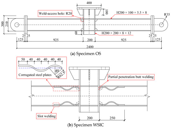
Figure 2.
Specimens OS and WSIC (dimensions in mm).
Figure 3 displays the test setup of OS and WSIC. The two ends of the specimens were connected by pins to provide hinge constraints. An MTS100T (1000 kN) hydraulic actuator was connected to the loading end of the failure column. The displacement-controlled method, with monotonically increasing upward tension, was employed to load the column to failure.
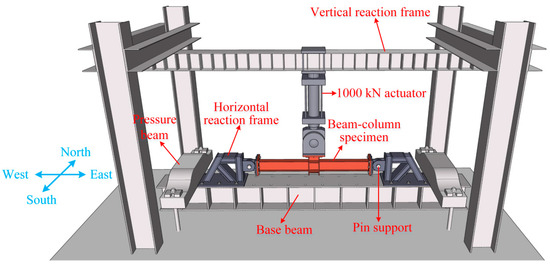
Figure 3.
Test setup.
3.2. Validation of the FE Results
To solve problems such as complex contact, model convergence, and material fracture, the explicit time integration method was used for numerical simulation in ABAQUS (vesion 6.14-AP), and the smooth analysis step method was used for vertical displacement loading to reduce the dynamic effects during the loading process. The FE models were developed using the physical dimensions of the test specimens. Hinged supports positioned at specimen ends corresponded to inflection points, where elastic deformation was considered negligible. Therefore, the model directly established a motion coupling connection between the beam end and the hinge point. Meanwhile, the three-dimensional translational degrees of freedom of the hinge point were restricted and only allowed for rotating in the plane, simulating the actual hinge boundary conditions. The bilinear strengthen constitutive model was adopted, and the yield strength, elastic modulus, and ultimate strength of the material were consistent with the measured values in the tests.
A hexahedral solid element C3D8R was employed to simulate all components. Usually, the finer the mesh, the higher the accuracy of the results. However, in practical engineering, excessively fine meshes can lead to a sharp increase in computational time costs, and when the number of meshes reaches a certain threshold, the improvement in accuracy becomes insignificant. Therefore, it is necessary to choose a reasonable number of meshes while ensuring calculation accuracy, and different sizes were used for the mesh partitioning of different components. Referring to the mesh partitioning method in reference [21], the column remained within the elastic range throughout loading, modeled with a relatively coarse mesh size of 30 mm. Beams away from the joint region utilized a 20 mm mesh size. To capture critical behavior, the joint region and corrugated plates received focused mesh refinement, employing a finer element size of 5 mm. Since full-penetration butt welding and slot welding remained undamaged during testing, their behavior was simulated using a “Tie” interaction. To simulate a fracture in partial-penetration butt welding, a discrete 8 mm wide cohesive element was employed [22]. Hard contact defined the normal interface behavior, while tangential behavior was modeled using a penalty function algorithm with a friction coefficient of 0.45 [23]. Based on the actual material properties listed in [21], the stress–strain constitutive relationship of steel was established (the nominal values were changed to the true values in two models). The fracture of steel was simulated using the element delete method.
Damage fracture simulation is a continuously focused-on issue in anti-collapse research, involving fields such as material microstructure and fracture mechanics. The specific damage simulation is described by fracture displacement, fracture strain, stress triaxiality, and strain rate [24]. A small fracture strain was adopted to accurately simulate the weld fracture in partial-penetration butt welding. Taking specimen WSIC as an example, the FE model is shown in Figure 4.

Figure 4.
FE model of specimen WSIC.
Figure 5 compares experimental and FE load–displacement curves. The FE results demonstrated strong agreement, with experimental trends throughout both elastic and plastic stages. The peak load and ultimate displacement discrepancies between experimental and FE curves were within 2% (the ratio of the FE results to experimental results was as follows: for the WSIC, the peak load and ultimate displacement were 1.02 and 0.99, respectively; for the OS, the peak load and ultimate displacement were 1.01 and 1.02, respectively), confirming excellent model validation.
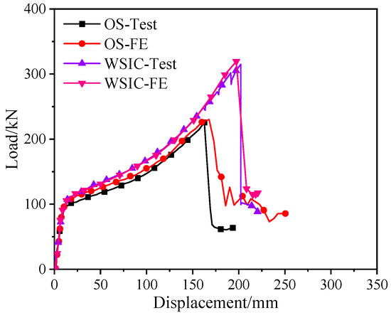
Figure 5.
Comparison of the load–displacement curves between the FE analysis and test results.
Figure 6 compares the FE and test results of the internal force development curves. As Figure 6 shows, the FE model effectively simulated the development of axial force and bending moment during the experimental loading process, and the model had high accuracy.
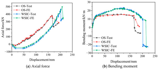
Figure 6.
Comparison of the axial force and bending moment curves between the test and FE analysis.
Moreover, after considering the damage parameters, the failure process and mode of two specimens were the same as the test phenomena, and the fracture location was also in good agreement with the test results (Figure 7). Especially for specimen WSIC, the inner corrugated plates at the upper flange were almost completely straightened, and then the upper flange fractured near the connection with the column, which was completely consistent with the phenomenon observed in the test. Therefore, the damage parameter setting in the FE model was effective.
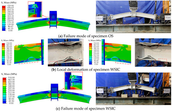
Figure 7.
Comparison of the failure process between the test and FE results.
Therefore, the above FE analysis can reproduce the main mechanical behaviors and failure phenomena of two specimens during testing. The FE models are accurate and reliable. The validated FE modeling method can provide a basis for further parametric analysis of the proposed novel joint.
4. FE Analysis of the Novel Joint
4.1. FE Modeling
A case of WSOC with the same size and as the specimen OS was designed, and four corrugated plates of the same size were installed on the outside of the joint area. The dimensions of the outer corrugated plate are shown in Figure 8. The anti-collapse behavior of the WSOC was investigated using the same modeling method, model parameters, boundary conditions, and loading scheme, as in Section 3.2. Figure 9 presents the FE model of the WSOC.
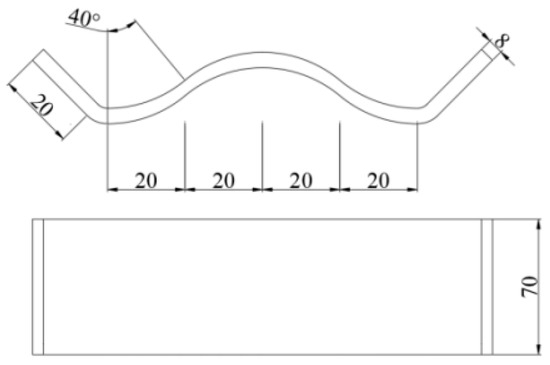
Figure 8.
Dimensions of the outer corrugated plate.
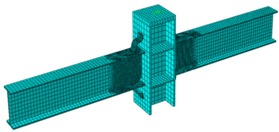
Figure 9.
FE model of the WSOC.
4.2. Analysis Results
Figure 10 shows the load–displacement curves of the OS, WSIC, and WSOC under FE analysis. Considering the consistency of the results, the load-displacement curves of the OS and WSIC also adopted the results of FE analysis. As shown in the figure, the overall trend of the curve of the WSOC was basically consistent with the other two curves, and the distinction in the descending segment was caused by the different states of the joints after fracture. The collapse resistance was provided by the beam mechanism in an elastic state. As the loading continued, nonlinear characteristic gradually became prominent, and the catenary mechanism began to take effect. Relative to the OS joint, the peak load and ultimate displacement of the WSOC significantly increased, even reaching twice that of the OS. Compared with the WSIC, the peak load and ultimate displacement of the WSOC increased by 17.0% and 16.3%, respectively. Compared with the OS and WSIC, the WSOC had the best anti-collapse behavior, and the obvious stage of resistance enhancement was formed. Adding external corrugated plates effectively improved the mechanical properties of the joints. In fact, from a simplified mechanical perspective, based on the lever principle, adding the outer corrugated plates provided a longer force arm for the joint compared with adding inner corrugated plates in the joint, which definitely achieved better mechanical effects.
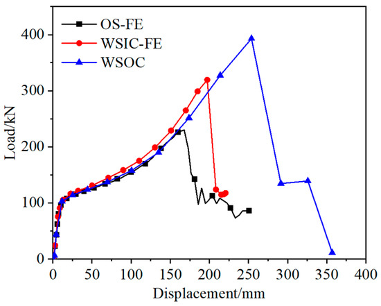
Figure 10.
Load–displacement curves of the WSOC, WSIC, and OS under FE analysis.
Figure 11 compares the internal force curves of the OS, WSIC, and WSOC at the section near the end support under FE analysis. The axial force displacement and bending moment displacement curves exhibited similar development trends across all three models. During initial loading, the bending moment increased linearly and rapidly, while axial force development was slow, indicating bending-dominated behavior in this phase. Subsequently, the growth rate of the bending moment decreased until stabilizing. Following cross-section fracture, the bending moment dropped abruptly. Axial force remained tensile throughout loading, with its growth rate accelerating progressively until extensive fracture occurred in the cross-section.
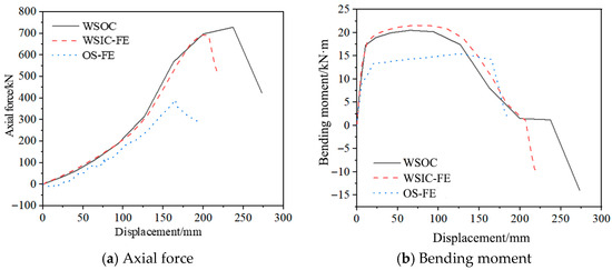
Figure 11.
Internal force curves of the OS, WSIC, and WSOC.
Compared with the OS, the bending moment and axial force of the WSIC and WSOC significantly increased. This result indicated that the corrugated plates made outstanding contributions to fully utilizing the beam mechanism and catenary mechanism of novel joints. Compared with the WSIC, there was no significant difference in bending moment of the WSOC, but the axial tension was greater, indicating that its catenary effect was more fully utilized. Therefore, the WSOC was superior to the WSIC, which had better catenary resistance and effectively improved the progressive collapse resistance of traditional steel-frame joints.
Furthermore, Figure 12 displays the failure process of the WSOC obtained from the FE results. As shown in the figure, in the early stage, the joint bore a larger bending moment and a smaller axial force. As the load increased, the axial force borne by the joint became larger, and then the upper flanges of the beams generated plastic zones on both sides of the corrugated plates which was beneficial for dissipating the strain energy of the joint (at this point, the bottom flanges of the beams underwent local buckling). Eventually, the tensile flange at the end of the beam fractured and extended toward the web of the beam (based on symmetry, after the corrugated plates in the tension zone were almost completely straightened, the upper flanges of the beams fractured simultaneously). The incorporation of outer corrugated plates induced an outward relocation of the plastic zone, thereby enhancing the progressive collapse resistance of conventional steel-frame joints.

Figure 12.
Failure process of the WSOC under FE analysis.
4.3. Parametric Analysis
Whether the anti-progressive collapse law of the scaled model is applicable to full-scale models under the same conditions is the key to the widespread application of the novel joint. Therefore, in addition to analyzing the WSOC with the same size as the OS, numerous supplemental analyses based on full-scale cases were executed on additional parameters, including the central angle (θc), corrugated plate thickness (t), corrugated plate width (w), length of circular arc (l), and welding angle (θw), as shown in Figure 1. The dimensions of the columns and beams were designed according to the current technical standard for steel structures in China [25], using narrow flanges (HN400 × 200 × 8 × 13 mm) and wide flanges (HW400 × 400 × 13 × 21 mm), H-shaped sections, respectively. The span of the cases was 4200 mm. The central angles varied at intervals of 20° within the range of 0–80°. The corrugated-plate thicknesses varied at intervals of 4 mm within the range of 5–21 mm. The corrugated plate widths varied at intervals of 20 mm within the range of 80–200 mm. The lengths of circular arc varied at intervals of 40 mm within the range of 80–240 mm. The welding angles varied at intervals of 15° within the range of 15–75°. The above changes were set based on actual conditions, and almost covered all the parameters of the corrugated plates that could be achieved on the beam–column joint mentioned above.
On the basis of WSOC-13-140-160-40-45, the FE analysis results with θc as a variation parameter while keeping other parameters unchanged are displayed in Figure 13. The failure modes of the WSOC under different central angles are exhibited in Figure 14. WSOC-13-140-160-40-45 signifies the WSOC with a corrugated plate thickness of 13 mm, corrugated plate width of 140 mm, length of circular arc of 160 mm, central angle of 40°, and welding angle of 45°.
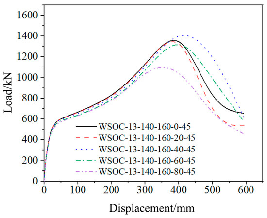
Figure 13.
FE analysis results with θc as a variation parameter.
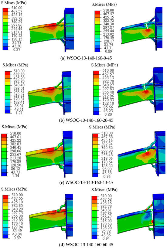
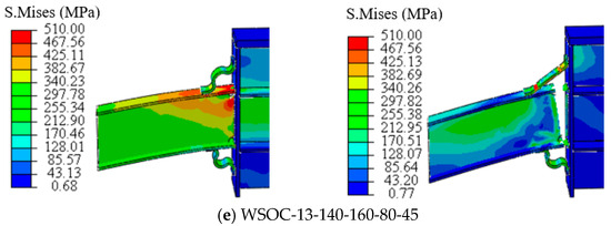
Figure 14.
Failure modes of the WSOC under different central angles.
The analysis revealed that the plastic zone was out-shifted completely when θc was less than 40°, and fractures occurred outside the joint area. Subsequently, the corrugated plates were straightened, and the joint was destroyed. The plastic zone was partially shifted outward when θc was greater than or equal to 40°. Especially when θc was equal to 40°, the corrugated plate fully participated in plasticity development. When θc was greater than 40°, the plastic zone was located at the upper flange of the beam near the failed column and fractures occurred at this location. The bearing capacity of the WSOC was the lowest when θc was 80°, indicating that the corrugated plates did not fully exert its function before the beam fractured. In fact, where the fracture occurred is not the focus, the key to improving the joint’s resistance to progressive collapse is whether a double-plastic zone (partial outward shift of the plastic zone) can be formed and whether the corrugated plates can play a role as soon as possible. Therefore, when θc was equal to 40°, the WSOC had the best anti-collapse behavior, and the central angle used in subsequent analysis was all 40°.
Similarly, the FE analysis results with t, w, l, and θw as variation parameters are displayed in Figure 15. Due to the limited length of the paper, the failure mode of each case was not provided.


Figure 15.
FE analysis results with variation parameters.
The results demonstrated that corrugated plate thickness minimally affected the bearing capacity of this joint type but significantly influenced the failure mode. When t was equal to 5 mm, the plastic zone concentrated within the beam–column connection area, where fracture occurred. In contrast, when t was greater than 5 mm, a double-plastic zone formed on the beam flange outside the connection area, ultimately fracturing. The WSOC achieved optimal collapse resistance when t was greater than or equal to 17 mm.
Corrugated plate width significantly influenced both the bearing capacity and failure mode of the WSOC joint. As w increased, the joint’s bearing capacity initially rose before decreasing. This was mainly because the excessively small w had a relatively small impact on the joint, while the excessively large w resulted in a relatively large proportion of the early beam mechanism, which limited the later play of the catenary mechanism. At w was equal to 80 mm or 100 mm, the plastic zone concentrated within the beam–column connection area, ultimately fracturing. By contrast, when w was greater than 100 mm, a double-plastic zone was formed on the flange of the beam outside the connection area, where fracture occurred. When w was equal to 100 mm, the best anti-collapse performance of the WSOC was achieved.
The lengths of circular arc minimally influenced the failure modes of this joint type, with fracture consistently occurring on the beam flange outside the connection area. However, when l was less than 200 mm, the corrugated plates failed to fully straighten. Conversely, when l was greater than 200 mm, complete straightening occurred, confirming effective utilization of the plates. Moreover, the ultimate bearing capacity increased progressively with l. Of significance, collapse resistance substantially improved when l was greater than or equal to 200 mm.
The welding angle has a significant effect on the bearing capacities and failure modes of this type of joint. As θw increased, the bearing capacity first increased and then decreased. This was mainly because the excessively small θw caused a sudden change in the stiffness of the connection between the corrugated plates and the beam–column, while the excessively large θw reduced the constraint of the corrugated plates on the beams and column. When θw was less than or equal to 45°, the plastic zone was concentrated in the connection area between the beam and column, where the fracture occurred. By contrast, when θw was greater than 45°, a double-plastic zone was formed on the flange of the beam outside the connection area, where fracture occurred. The best anti-collapse performance of the WSOC was achieved when θw was between 30° and 45°.
Therefore, appropriate parameters of the outer corrugated plates are necessary to optimize the progressive collapse resistance of traditional steel-frame joints. The full development of plasticity and the formation of double-plasticity zones can not only effectively alleviate stress concentration at the joint, but also facilitate the dissipation of strain energy at the joint, and then improve bearing capacity and ductility. Based on the extensive parameter analysis mentioned above, to maximize the effectiveness of the corrugated plates, the design suggestions for the outer corrugated plates in the WSOC are illustrated below:
(1) θc = 40°;
(2) t = 1.3~1.6 tf, where tf is the beam-flange thickness;
(3) w = 0.5B, where B is the beam-flange width;
(4) l = 0.5~0.6h, where h is the beam height;
(5) θw = 30~45°.
In fact, the afore-mentioned suggestions also take into account the engineering application requirements that the outer corrugated plates should not be higher than the surface of the concrete floor slab. In addition, compared with the design suggestions of the WSIC in the literature [21], in order to effectively improve the anti-progressive collapse performance of welded steel frame joints, design recommendations of the WSOC are more stringent. This is caused by a complex outer corrugated plate form. However, due to the larger operating space of the WSOC, the number of the corrugated plates required on a single joint in the WSOC is only half of that in the WSIC (the material and labor of the corrugated plates was reduced by 50%). Therefore, the WSOC has a broader application prospect than the WSIC.
5. Application of the Corrugated Plates
5.1. Full-Scale Beam–Column Joint Case
According to the proposed suggestions, the beam–column joint in Section 4.3 (full-scale beam–column joint) was strengthened with the following dimensions (WSOC-20-100-200-40-45): the central angle, corrugated plate thickness, corrugated plate width, length of circular arc, and welding angle of the outer corrugated plates were 40°, 20 mm, 100 mm, 200 mm, and 45°, respectively. Figure 16 displays the reinforcement effect of the corrugated plates on the corresponding traditional beam–column joint under the design proposals.
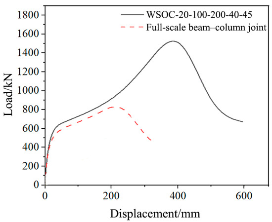
Figure 16.
Reinforcement effect of the corrugated plates on the corresponding traditional beam–column joint under the design proposals.
Compared with the traditional full-scale beam–column joint designed in Section 4.3, the bearing capacity and ultimate displacement of the WSOC-20-100-200-40-45 designed under reasonable suggestions increased by 88.3% and 72.3% respectively. Therefore, simply from the perspective of joints, the design suggestions provided in the paper were highly effective. In fact, the proposed design suggestions given in this paper may not necessarily be optimal, but this does not affect the promotion and application of the novel joint. This is because there is no standard threshold for the degree of joint reinforcement itself. Compared with traditional joints, the novel type of joint only increases the amount of steel by a little bit, but its bearing capacity and ductility have been nearly doubled, which is undoubtedly very successful.
5.2. Full-Scale Steel-Frame Case
Whether the outer corrugated plate is still effective in terms of overall structures is the key to its application. Three full-scale four-span plane steel-frame models were analyzed, namely traditional steel frame (TF), steel frame strengthened by outer corrugated plates (FSOC), and steel frame strengthened by inner corrugated plates (FSIC). The basic dimensions of three frames were the same, with a floor height of 3 m, a total of 6 floors, and a column spacing of 4.8 m. The cross-sectional dimensions and material properties of beams and columns were identical to those specified in Section 4.3. The central angle, corrugated plate thickness, corrugated plate width, length of circular arc, and welding angle of the outer corrugated plates were 40°, 20 mm, 100 mm, 200 mm, and 45°, respectively. The inner corrugated plates featured a 20° central angle, a 20 mm thickness, and a 200 mm circular arc length. Figure 17 illustrates the geometric configuration and FE model of the three frames, where S1–S6 denote cross-sectional positions designated for subsequent analysis. Pushdown analysis was executed by imposing a vertically downward displacement on the first-floor middle column.
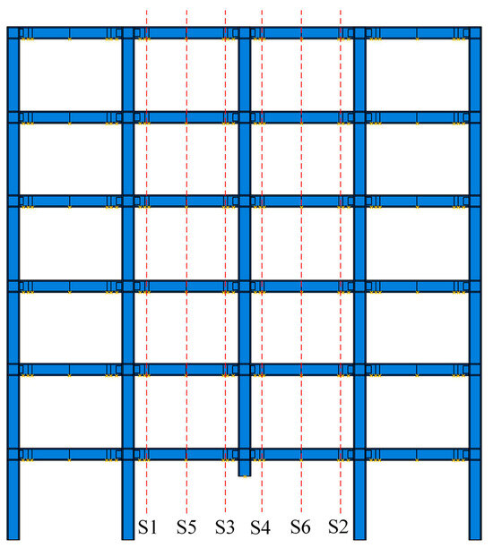
Figure 17.
FE model of the three frames.
Figure 18 presents the FE analysis results for three steel-frame structures subjected to first-floor middle column failure. Compared to the TF joint, the FSIC exhibited 18.3% and 23.8% increases in peak load and ultimate displacement, respectively. The FSOC demonstrated greater improvements, with peak load and ultimate displacement rising by 19.8% and 38.3%, respectively. These results indicate that outer corrugated plates significantly enhance progressive collapse resistance compared to both TF and FSIC configurations under column-loss scenarios. Notably, the structural-level improvements in peak load and ultimate displacement achieved through outer corrugated plate reinforcement were relatively modest compared to joint-scale enhancements. This was because resisting progressive collapse was a systematic and holistic issue that heavily relied on the redundancy and internal force redistribution ability of structures. Enhancing the performance of a single joint (even a critical joint) only optimized the performance of a component in the system under extreme conditions but could not increase the number of backup paths. Furthermore, the Vierendeel mechanism also constituted a significant contributor to global structural resistance against progressive collapse.
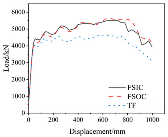
Figure 18.
FE analysis results of three steel-frame structures under the failure of the middle column on the first floor.
The collapse resistance development curves of each floor were calculated by Equation (1). To quantitatively evaluate the specific contribution of the resistance improvement of each floor before and after strengthening, a comparative analysis was conducted using the energy of the structure during the collapse process.
where, Pi represents the collapse resistance of each floor. PFi and PCi provide the collapse resistance for the bending mechanism and catenary mechanism of each floor, respectively. NC(i+1) and NC(i) denote axial forces in columns at floor levels (i + 1) and (i), respectively.
Figure 19 compares the collapse resistance development curves of each floor between the FSOC and TF. Compared with the TF, the average collapse resistance of each floor of the FSOC increased by 18.1%, with the highest increase being 22.9%. The outer corrugated plates demonstrated a more pronounced effect in enhancing collapse resistance for middle floors (floors 3 to 5).
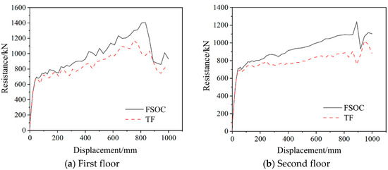
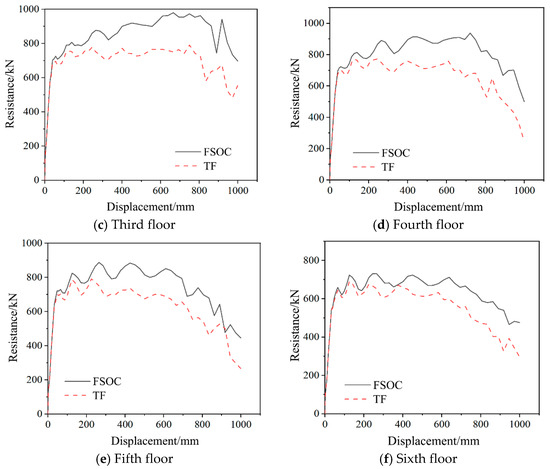
Figure 19.
Comparison of the collapse resistance development curves of each floor between the FSOC and TF.
Figure 20 compares the internal force curves of the FSOC and TF on each floor at different cross-sections. As shown in the figure, both models exhibited consistent development trends and magnitudes for beam-end bending moments. However, axial force progression diverged slightly due to Vierendeel mechanism activation throughout the structural frame. The axial tension was mainly concentrated in the lower floors, and the upper floors were mainly under compression. It was worth noting that the sixth-floor beam exhibited negative axial forces prior to reaching 340 mm displacement in the FSOC. As the displacement increased, the negative value began to transform into a positive value, corresponding to the beam transitioning from a compressive state to a tensile state.
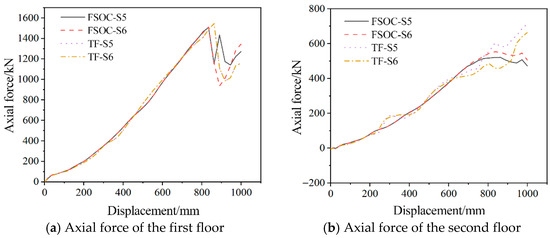
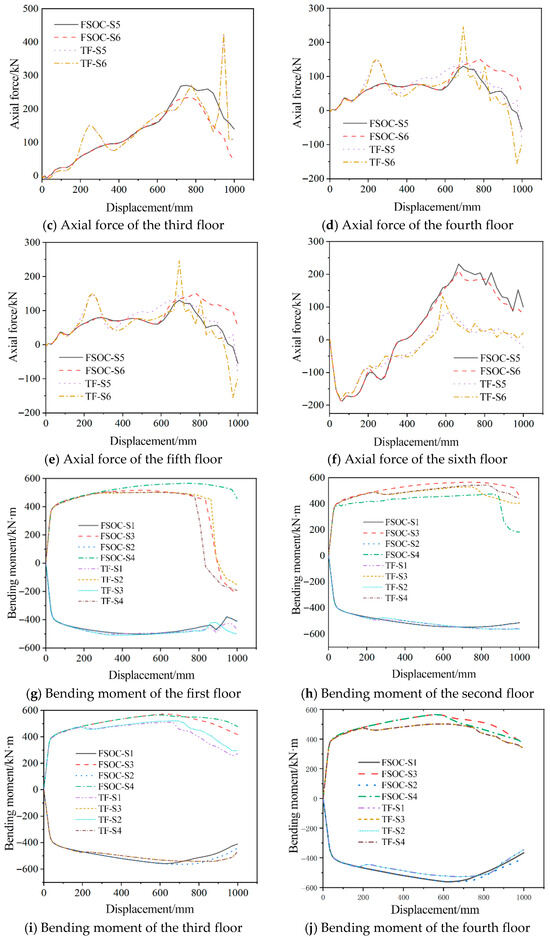
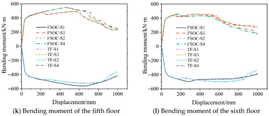
Figure 20.
Comparison of the internal force curves of the FSOC and TF on each floor at different cross-sections.
Additionally, the anti-collapse performance of the FSOC under the failure of the side column and secondary side column was analyzed. Figure 21 compares the load–displacement curves of the FSOC and TF joints subjected to side column and secondary side column failure scenarios.
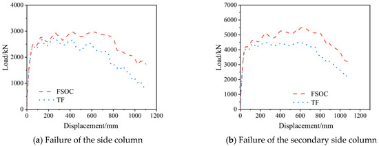
Figure 21.
Load–displacement curves of the FSOC and TF under the failure of the side column and secondary side column.
Under side column failure conditions, the FSOC exhibited 15.5% and 54.7% increases in peak load and ultimate displacement, respectively, versus the TF joint. For secondary side column failure, these improvements were 23.4% (peak load) and 39.8% (ultimate displacement). When the side column or secondary column failed, the trend of changes in the structural bearing capacity and deformation was basically the same as when the middle column failed (the internal force development of each floor will not be repeated), indicating that adding the outer corrugated plates in the structure can resist progressive collapse under different column failures.
Furthermore, the anti-collapse performance of the FSOC with a total height of nine and twelve floors under the failure of the middle column on the first floor was also analyzed. The analysis results are shown in Figure 22. Specifically, FSOC-9 and TF-9 denote the FSOC and TF with a total height of nine floors, and so on. Compared with the TF-9, the peak load of the FSOC-9 increased by 22.9% and the ultimate displacement increased by 26.0% when the middle column failed. Similarly, compared with the TF-12, the ultimate load and displacement of the FSOC-12 increased by 24.4% and 18.1%, respectively. From the perspective of bearing capacity, the application effect of the outer corrugated plates was better in the structure with higher overall height. However, after using the outer corrugated plates, the ductility of the structure with lower overall height was significantly improved. Due to limited examples, the influence of the number of floors on the anti-collapse performance of the FSOC is not yet known, and further analysis can be conducted in the future.
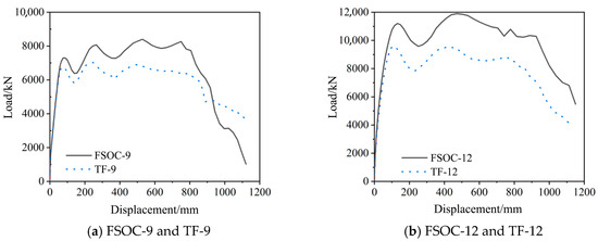
Figure 22.
Load–displacement curves of the FSOC and TF, with a total height of nine and twelve floors under the failure of the middle column on the first floor.
Therefore, the outer corrugated plates significantly improved the progressive collapse resistance of steel-frame structures.
6. Conclusions
A novel reinforced joint named the welded steel-frame joints strengthened by outer corrugated plates was proposed, which involved welding outer corrugated plates at the connection between beams and columns. The progressive collapse resistance of the novel joint was comprehensively investigated via extensive FE analysis using validated modeling methodologies. Key conclusions were as follows:
(1) Relative to the OS joint, the WSOC exhibited significant enhancements in both peak load and ultimate displacement. Compared with the WSIC, these performance metrics increased by 17.0% and 16.3%, respectively. Both in terms of construction convenience and mechanical behavior, WSOC is superior to WSIC.
(2) Design suggestions for the outer corrugated plates in welded steel-frame joints are as follows: θc = 40°; t = 1.3~1.6 tf; w = 0.5B; l = 0.5~0.6h; θw = 30~45°.
(3) Compared with the traditional full-scale beam–column joint designed in Section 4.3, the bearing capacity and ultimate displacement of the WSOC-20-100-200-40-45 designed under reasonable suggestions increased by 88.3% and 72.3% respectively. Simply from the perspective of joints, the design suggestions provided in the paper were highly effective.
(4) Compared with the TF, the peak load and ultimate displacement of the FSOC increased by 19.8% and 38.3% respectively. The structural-level improvements in peak load and ultimate displacement achieved through outer corrugated plate reinforcement were relatively small compared to joint-scale enhancements. The outer corrugated plates demonstrated a more pronounced effect in enhancing collapse resistance for middle floors (floors 3 to 5).
(5) The novel type of joint had a simple form and clear mechanical principles, which fully exerted the catenary capacity of the steel beams. The outer corrugated plates significantly improved the anti-progressive collapse performance of steel-frame structures.
This paper only focuses on the anti-progressive collapse performance of welded steel frame joints improved by outer corrugated plates. Future research work will concentrate on applications of such joints, including optimization of the corrugated plates, how to consider floor slabs, quantitative contribution of the corrugated plates in the structure, and whether the outer corrugated plates need to be fully added in all joints of the structure.
Author Contributions
Y.W.: Writing–original draft, Data curation, Funding acquisition. Y.-X.Y.: Conceptualization, Software, Writing–review and editing. L.-M.T.: Methodology. All authors have read and agreed to the published version of the manuscript.
Funding
This research was funded by [Natural Science Basic Research Program of Shaanxi Province], grant number [2024JC-YBQN-0607].
Data Availability Statement
The data will be available as requested.
Conflicts of Interest
The authors declare no conflicts of interest.
References
- Elkady, N.; Nelson, L.A.; Weekes, L.; Makoond, N.; Buitrago, M. Progressive collapse: Past, present, future and beyond. Structures 2024, 62, 106131. [Google Scholar] [CrossRef]
- Singh, H.; Bhandari, M. A contemporary review on progressive collapse. IOP Conf. Ser. Earth Environ. Sci. 2024, 1326, 012027. [Google Scholar] [CrossRef]
- Ferraioli, M.; Laurenza, B.; Lavino, A.; De Matteis, G. Progressive collapse analysis and retrofit of a steel-RC building considering catenary effect. J. Constr. Steel Res. 2024, 213, 108364. [Google Scholar] [CrossRef]
- Buitrago, M.; Setiawan, A.; Makoond, N.; Gerbaudo, M.L.; Marin, L.; Cetina, D.; Caredda, G.; Sempertegui, G.; Oliver, M.; Adam, J.M. Failure analysis after the progressive collapse of a precast building. Eng. Struct. 2024, 321, 118893. [Google Scholar] [CrossRef]
- Lin, S.-C.; Yang, B.; Kang, S.-B.; Xu, S.-Q. A new method for progressive collapse analysis of steel frames. J. Constr. Steel Res. 2019, 153, 71–84. [Google Scholar] [CrossRef]
- Qiu, L.; Lin, F.; Yang, X.-J. Pre-relaxed cables for improving progressive collapse resistance of RC frame subassemblages considering slabs. Eng. Fail. Anal. 2024, 165, 108803. [Google Scholar] [CrossRef]
- Qian, K.; Lan, X.; Deng, X.-F.; Fu, F. Load resistance of masonry infilled panels for steel frames to mitigate progressive collapse caused by middle column missing. J. Build. Eng. 2024, 97, 110757. [Google Scholar] [CrossRef]
- Zhong, W.-H.; Wu, D.; Tan, Z.; Qiu, Y.-Z.; Fan, C.-L. Progressive collapse behavior of beam–column structures with corrugated web openings. J. Constr. Steel Res. 2024, 223, 108982. [Google Scholar] [CrossRef]
- Dinu, F.; Marginean, I.; Dubina, D.; Petran, I. Experimental testing and numerical analysis of 3D steel frame system under column loss. Eng. Struct. 2016, 113, 59–70. [Google Scholar] [CrossRef]
- Meng, B.; Zhong, W.; Hao, J.; Song, X. Improving anti-collapse performance of steel frame with RBS connection. J. Constr. Steel Res. 2020, 170, 106119. [Google Scholar] [CrossRef]
- Wang, Y.; Li, J.-Z.; Bai, C.; Shen, H.-X.; Tian, L.-M. Novel beam–column joint with the folded plates for improving progressive collapse resistance of steel-frame structures. Structures 2024, 61, 106047. [Google Scholar] [CrossRef]
- Tian, L.-M.; Li, M.-H.; Li, L.; Li, D.-Y.; Bai, C. Novel joint for improving the collapse resistance of steel frame structures in column-loss scenarios. Thin-Walled Struct. 2022, 182, 110219. [Google Scholar] [CrossRef]
- Alembagheri, M.; Sharafi, P.; Tao, Z.; Hajirezaei, R.; Kildashti, K. Robustness of multistory corner-supported modular steel frames against progressive collapse. Struct. Des. Tall Spéc. Build. 2021, 30, e1896. [Google Scholar] [CrossRef]
- Zhang, L.; Li, H.; Wang, W. Retrofit strategies against progressive collapse of steel gravity frames. Appl. Sci. 2020, 10, 4600. [Google Scholar] [CrossRef]
- Qin, X.; Wang, W.; Chen, Y.; Bao, Y. A special reinforcing technique to improve resistance of beam-to-tubular column connections for progressive collapse preventions. Eng. Struct. 2016, 117, 26–39. [Google Scholar] [CrossRef]
- Han, Q.; Li, X.; Liu, M.; Spencer, B.F., Jr. Performance analysis and macromodel simulation of steel frame structures with beam-column joints using cast steel stiffeners for progressive collapse prevention. Thin-Walled Struct. 2019, 140, 404–415. [Google Scholar] [CrossRef]
- Meng, B.; Li, F.; Zhong, W.; Zheng, Y.; Du, Q. Strengthening strategies against the progressive collapse of steel frames with extended end-plate connections. Eng. Struct. 2023, 274, 115154. [Google Scholar] [CrossRef]
- Qiao, H.; Xie, X.; Zheng, J.; Xing, Z.; Chen, Y.; Wei, J. Progressive collapse behavior of beam-to-column connections involving flange openings. Eng. Struct. 2023, 284, 115972. [Google Scholar] [CrossRef]
- Kiakojouri, F.; De Biagi, V.; Chiaia, B.; Sheidaii, M.R. Strengthening and retrofitting techniques to mitigate progressive collapse: A critical review and future research agenda. Eng. Struct. 2022, 262, 114274. [Google Scholar] [CrossRef]
- Wei, J.-P.; Tian, L.-M.; Guo, Y.; Qiao, H.-Y.; Jiao, Z.-A.; Bao, Y. Seismic performance of a double-hinge steel frame joint with replaceable T-shape energy dissipator. J. Constr. Steel Res. 2022, 199, 107630. [Google Scholar] [CrossRef]
- Bai, C.; Tian, L.-M.; Kou, Y.-F.; Zhong, W.-H.; Li, L. Performance analysis of steel frame joints reinforced against progressive collapse by partially-penetrated butt-welded corrugated steel plates. J. Constr. Steel Res. 2022, 198, 107565. [Google Scholar] [CrossRef]
- Karlina, A.I.; Balanovskiy, A.E.; Kondratiev, V.V.; Romanova, V.V.; Batukhtin, A.G.; Karlina, Y.I. An Investigation into the behavior of cathode and anode spots in a welding discharge. Appl. Sci. 2024, 14, 9774. [Google Scholar] [CrossRef]
- Wang, W.; Fang, C.; Qin, X.; Chen, Y.; Li, L. Performance of practical beam-to-SHS column connections against progressive collapse. Eng. Struct. 2016, 106, 332–347. [Google Scholar] [CrossRef]
- Li, L.; Wang, W.; Chen, Y.; Lu, Y. Effect of beam web bolt arrangement on catenary behaviour of moment connections. J. Constr. Steel Res. 2015, 104, 22–36. [Google Scholar] [CrossRef]
- JGJ99–2015; Technical Specification for Steel Structure of Tall Building. Ministry of Construction of China: Beijing, China, 2015.
Disclaimer/Publisher’s Note: The statements, opinions and data contained in all publications are solely those of the individual author(s) and contributor(s) and not of MDPI and/or the editor(s). MDPI and/or the editor(s) disclaim responsibility for any injury to people or property resulting from any ideas, methods, instructions or products referred to in the content. |
© 2025 by the authors. Licensee MDPI, Basel, Switzerland. This article is an open access article distributed under the terms and conditions of the Creative Commons Attribution (CC BY) license (https://creativecommons.org/licenses/by/4.0/).