Article

BIM-Enabled Two-Phase Optimization Framework for Automated Masonry Layout Efficiency

1
School of Infrastructure Engineering, Nanchang University, 999# Xuefu Ave., Honggutan District, Nanchang 330031, China
2
ZhongMei Engineering Group Ltd., Kowloon Lake International Expo Center, Shangrao St., Honggutan District, Nanchang 330038, China
*
Author to whom correspondence should be addressed.
Buildings 2025, 15(17), 3051; https://doi.org/10.3390/buildings15173051
Submission received: 26 July 2025 / Revised: 13 August 2025 / Accepted: 25 August 2025 / Published: 26 August 2025
(This article belongs to the Section Building Structures)

Abstract

Masonry construction remains labor-intensive, with current block placement predominantly dependent on workers’ empirical knowledge. Lack of systematic cutting plans induces substantial material waste and rework, adversely affecting sustainability. We propose a two-phase optimization framework to automate and enhance masonry block arrangement efficiency. Phase 1 decomposes masonry structures into optimizable subregions by geometric features, documenting each region’s geometry and position to generate optimization datasets. Phase 2 implements a computational module using the Social Network Search (SNS) algorithm to optimize subregion layouts, recording post-optimization block coordinates and dimensions. Finally, it materializes layout configurations and generates block quantity schedules to provide precise material demand data. An integrated prototype system was implemented in four specialized block arrangement scenarios and one building case study, validating both functionality and efficiency.

1. Introduction

Sustainable development and intelligent design are gaining prominence in the Architecture, Engineering, and Construction (AEC) industry [1,2,3,4]. Masonry remains among the most prevalent global structural systems [5,6]. Masonry construction relies on empirical knowledge for unit cutting and placement [7]. This experience-based approach generates significant material waste and rework. Traditional masonry demands highly skilled labor to ensure consistent quality. These labor-intensive processes incur substantial costs. The AEC industry faces an acute skilled labor shortage [8,9]. Diminishing skilled labor escalates construction errors, exacerbating raw material waste from suboptimal cutting.
Waste bricks comprise 30–40% of masonry construction and demolition debris. Few intact units are reusable, while residual waste bricks predominantly undergo landfilling. Limited landfill space availability causes waste bricks to consume significant land resources. Disposal also incurs costs for landfilling and transportation, elevating project expenditures [10]. Brick production requires substantial coal combustion, emitting significant airborne pollutants. Consequently, brick waste represents both embodied energy loss and environmental degradation [11].
Minimizing brick waste across the building life cycle is crucial to reduce project costs and environmental burdens [12,13]. Rigorous block arrangement planning during design minimizes on-site cutting waste and rework. Non-modular wall dimensions necessitate adaptive brick cutting, yet optimized layout designs can substantially reduce such waste. Empirical studies quantify cutting waste at 16.29% of masonry costs, with layout optimization reducing waste costs by 6.59% [14]. Suboptimal planning decisions generate significant construction waste and demolition waste. Consequently, meticulous pre-construction design effectively reduces material waste [15,16].
In current design practice, detailed masonry layout design is typically manually drafted by designers using Computer-Aided Design (CAD) software [17]. Designers plan block arrangements according to industry protocols and annotate dimensional and positional details on construction drawings. This approach suffers from three critical limitations:
Manual calculation burdens: Brick dimensions and positions require laborious manual computation, rendering the layout process time-intensive and error-prone, thereby causing substantial designer frustration [18];
2D representation constraints: Two-dimensional drawings fail to accurately visualize complex joint details, hindering effective on-site construction guidance;
Imprecise quantity estimation: Block quantities can only be approximated via volume ratios between walls and individual units, preventing precise procurement and usage data tracking.
Consequently, the absence of efficient design assistive methods perpetuates block arrangement design as a labor-intensive undertaking.
Since the early 21st century, the construction industry has undergone significant digital transformation through emerging technologies like Building Information Modeling (BIM), mixed reality, and digital twins [19,20]. Among these, BIM has proven particularly effective for reducing project costs and enhancing coordination [21]. BIM enables digital modeling of complex structures with multidimensional attributes (e.g., thermal properties, cost data), while programmatic scripting facilitates data extraction for algorithmic optimization [22]. BIM-facilitated automation reduces design errors and material waste, thereby minimizing on-site errors and lowering rework probability and construction waste generation. BIM implementations have advanced material design, construction emissions mitigation, site management, and supply chain optimization—collectively targeting material waste reduction in engineering practice [23,24,25,26,27].
As BIM technology evolves, researchers have attempted its adaptation to masonry structures. Some scholars proposed using drones to replace bricklayers for automated construction based on BIM models, thereby reducing labor dependency. However, substantial manual preprocessing remains required for model refinement due to the lack of precise design-support methods [28]. Addressing inefficient manual modeling, A. Monteiro et al. [29] utilized BIM’s built-in functions to automate block quantity calculations through parametric arrays, yet this approach fails to accommodate non-modular wall layouts—requiring manual adjustments for cut units. Moreover, excessive array operations cause BIM software lag, rendering it impractical for large-scale masonry.
Researchers also explored BIM-integrated solutions. Sharif et al. [30] developed a masonry unit database for digital representation and information exchange, establishing foundational data interoperability. Cavieres et al. [31] theorized a computational representation method involving geometric decomposition of masonry components into specialized zones for selective detailing. Given the complexity of non-modular masonry design, algorithmic solutions emerged. Tarek Zaki et al. [32] implemented parametric assembly algorithms to generate virtual BIM models for non-modular walls, but these models lacked layout granularity. C. Xu et al. [33] created a computational module using Neighbor Field Optimization to adjust block dimensions and joint thicknesses, though optimized results were confined to single walls by overlooking boundary conditions. J. Liu et al. [17] proposed a two-step memetic algorithm for multi-scale wall layouts with visualizations, yet wall junctions still failed to form structurally sound connections. Collectively, existing work achieves non-modular wall layouts but remains limited to isolated rectangular walls, neglecting critical inter-wall junction resolutions.
This study develops a two-phase systematic framework from a holistic masonry optimization perspective. The framework rapidly generates rational structural layouts while ensuring robust structural performance and compliance with architectural aesthetics. Its core objective is to benchmark masonry construction standards while accommodating on-site constraints, thereby reducing material wastage and preventing unnecessary time expenditures. The approach demonstrates dual advantages: enhanced applicability through standardized brick layout at wall junctions, and intelligent cutting pattern optimization that minimizes brick loss through a dedicated algorithm.
The paper is structured as follows: Section 2 introduces masonry layout specifications and adopted strategic principles.
Section 3 elaborates on the framework integrating BIM-API with Social Network Search (SNS).
Section 4 validates framework feasibility via four specialized block arrangement scenarios and full-scale architectural case studies.

2. Preliminary

This section introduces two conventional masonry construction methods as research subjects, while establishing standardized joint detailing protocols for diverse wall junctions and coordinated spatial arrangement strategies for non-modular walls. These serve as reference templates for subsequent architectural software development, ensuring compliance with practical constructability requirements.

2.1. Masonry Requirements

As shown in Figure 1, masonry units (MUs) represent the fundamental components of masonry structures. Fabricated from quasi-brittle materials (e.g., natural stone, fired/unfired bricks), MUs bond through mortar joints to form walls [34]. In masonry walls:
  • Bricks with long edges parallel to the wall face are stretchers;
  • Those perpendicularly oriented are headers.
Each horizontally layered row of MUs defines a course, while mortar joints between courses and adjacent units are designated horizontal joints and vertical joints, respectively [29]. Mortar joints must maintain geometric regularity to ensure uniform force transfer paths, thereby preventing localized stress concentrations and enhancing structural stability. Joint thickness requires precise control: excessive thickness compromises bonding integrity, whereas insufficient thickness diminishes strain accommodation capacity, impairing stress and load redistribution [35].
According to China’s Code for Construction of Masonry Structures (GB 50924-2014), mortar joint thickness should be maintained at 10 mm with a tolerance of ±2 mm (minimum 8 mm, maximum 12 mm) for both horizontal and vertical joints. Vertical joints between upper and lower courses must be staggered to achieve required lap ratios. Proper lap ratios enhance structural bearing capacity by distributing loads uniformly across units, with regional minimum requirements as follows: ≥1/3 unit length in China, ≥1/4 unit height per US ACI 530, and ≥2/5 unit length under Eurocode 6. To minimize cutting waste and ensure aesthetic compliance, full-sized units should be prioritized during construction. Simultaneously, the variety of unit dimensions within any single wall should be minimized to improve construction efficiency. Constructed dimensions must conform to design specifications: horizontally, the built length shall match the wall length without deviation; vertically, the cumulative course height shall align with wall height. Units must not exceed wall boundaries. US and EU standards share identical requirements with China for all criteria except joint thickness and lap ratios, as formally tabulated in Table 1.

2.2. Placement Strategy

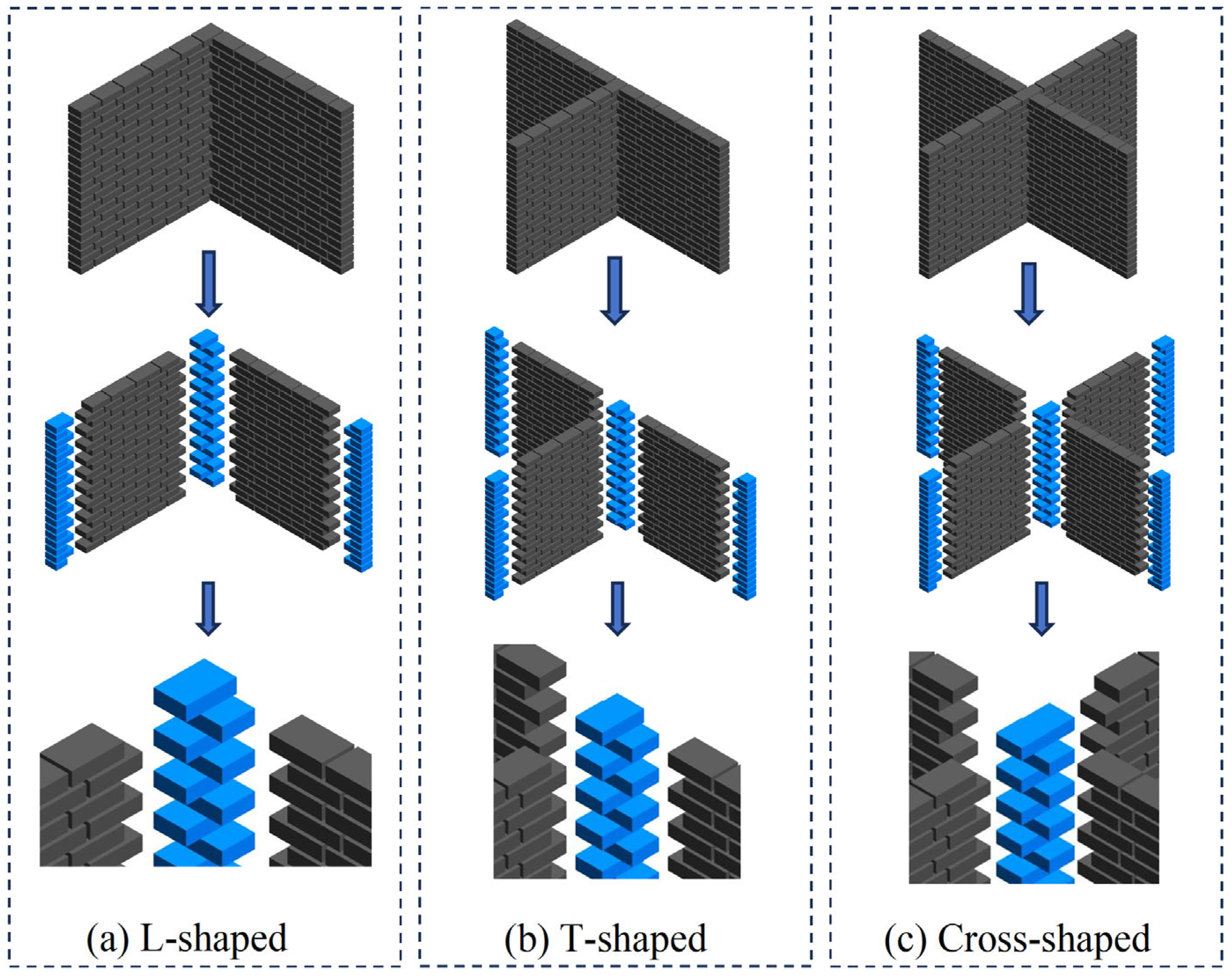
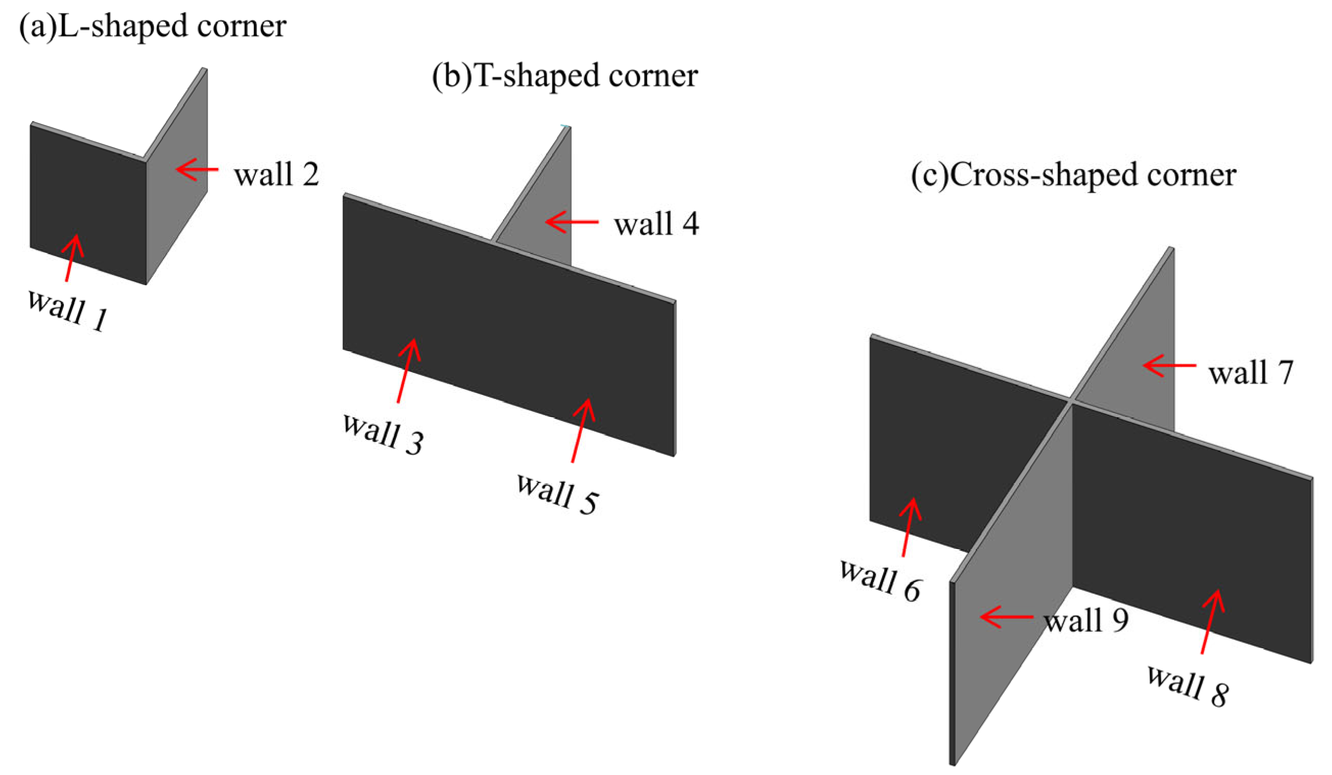
In masonry construction, interconnected walls form connection zones, typically at corners. These wall connection zones are geometrically classified as L-shaped, T-shaped, or cross-shaped. Detailing at masonry connection nodes critically influences structural mechanical properties. Orthogonal wall toothing should exhibit high compatibility, with mortar joint dimensions strictly controlled to match adjacent sections. As critical bonding mechanisms, connection joints integrate walls into effective structural units. Additionally, masonry units at joints must satisfy minimum overlap ratios per Table 1 specifications.
The quantity of MUs in masonry structures, combined with integrated global geometries and localized bonding patterns, substantially complicates layout design. Direct full-structure optimization increases computational dimensionality, necessitating geometric decomposition for regional subdivision. Inter-wall junction design functions as the key criterion for segmenting Masonry Subsystems. These junctions require rule-based configurations to ensure effective inter-unit connectivity. Specialized geometric constraints at junctions achieve mechanically interlocking connections.
As shown in Figure 2, each masonry wall comprises two terminal joints and a continuous wall segment. Terminal joints are classified into four typologies:
  • Cross-joints: Connect four orthogonally intersecting walls;
  • T-joints: Interconnect three walls in T-configurations;
  • L-joints: Connect two perpendicular walls at right-angle corners;
  • Boundary joints: Terminate free wall ends while maintaining foundation vertical alignment.
As structural connectors, these joints integrate discrete regions into unified systems. Their geometry must satisfy three constraints:
  • Fixed transverse layout per course;
  • Mandatory connection to coordination units;
  • Staggered lap lengths between consecutive courses.
Prioritizing terminal joint block arrangements reduces masonry layout optimization from 3D to 2D space. Constrained terminal joints shift optimization focus to cutting/layout schemes in continuous wall segments. The block layout problem is formulated as a two-dimensional bin packing problem. Geometric constraints partition structures into rectangular containers. Terminal joints function as pre-placed rectangular items occupying partial container areas. These items maintain fixed horizontal coordinates but vertically adjust per mortar joint thickness. Computational models and formulas for block optimization are detailed in Section 3.
During construction, masons typically lay bricks from both ends toward the center. When wall lengths deviate from modular dimensions, full bricks require cutting for layout completion. Minimum cutting thresholds apply:
  • Lightweight blocks: unusable when cut below 1/4 total length;
  • Aerated concrete blocks: typically discarded below 1/3 total length (non-mandatory).
To account for material-specific variations, the minimum usable length equals the brick’s width. Coordination bricks are incorporated per course with these characteristics to achieve rational non-modular layouts respecting length constraints:
  • Position: Two units per course at both wall ends;
  • Modular sizing: Length equals nominal brick width in modular walls;
  • Non-modular adaptation: Maximum length equals full brick length in non-modular walls;
  • Adaptive sizing: The adjustable length range of the bricks is 0 c b l l b w b;
  • Course synchronization: Adjustments synchronized across coordination bricks in alternating courses.
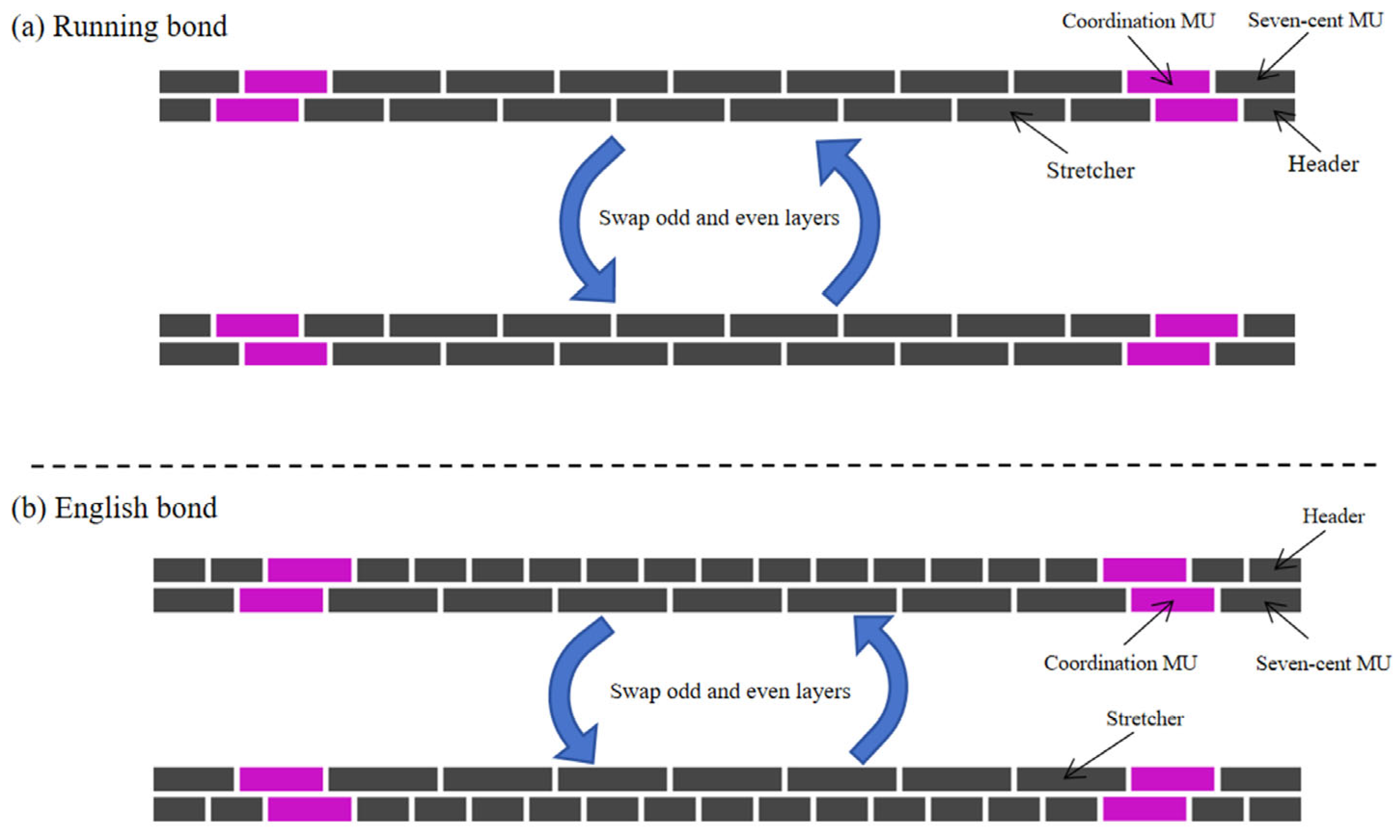
This research adopts two fundamental bond patterns: Running Bond and English Bond. These configurations epitomize the opposing mechanical principles of continuous versus staggered joints, encompassing diverse construction complexities, wall thickness variations, and aesthetic expressions. Serving as the essential building blocks for comprehending advanced masonry techniques, they constitute the foundational lexicon of structural assembly—demonstrating exceptional representativeness and significant research value.
Coordination layout rules for both configurations are detailed below, each governed by two layout constraints distinguished by header brick arrangements in alternating courses. This systematic approach establishes fixed geometric constraints at wall terminals, facilitating subsequent subdivision for regional optimization.
As shown in Figure 3 in the Running Bond layout scenario, headers are placed at the ends of odd courses, while three-quarter bats are positioned at the ends of even courses. The bat length l b a t , = 1 / 2 l b + w b defines the first fundamental layout constraint. To enable interconnection between wall ends, the positions of headers and bats are swapped between odd and even courses under the first constraint, ensuring alignment of masonry joint zones in both elevation and profile views. Consequently, walls employing these two layout scenarios exhibit mutual perpendicularity in plan view.
In dual layout scenarios for the English Bond, the first configuration constrains three-quarter bats at odd-course ends and dual headers at even-course ends, with their combined length plus intermediate vertical joint thickness equaling full brick length; whereas the second configuration interchanges these odd/even course placements.
All aforementioned constraints share identical unit types: headers, three-quarter bats, full bricks, and coordination bricks. Coordination bricks are symmetrically placed at each course end within the layout plane, with an initial length equal to the brick width and a maximum length equal to the brick length.

3. Proposed Framework

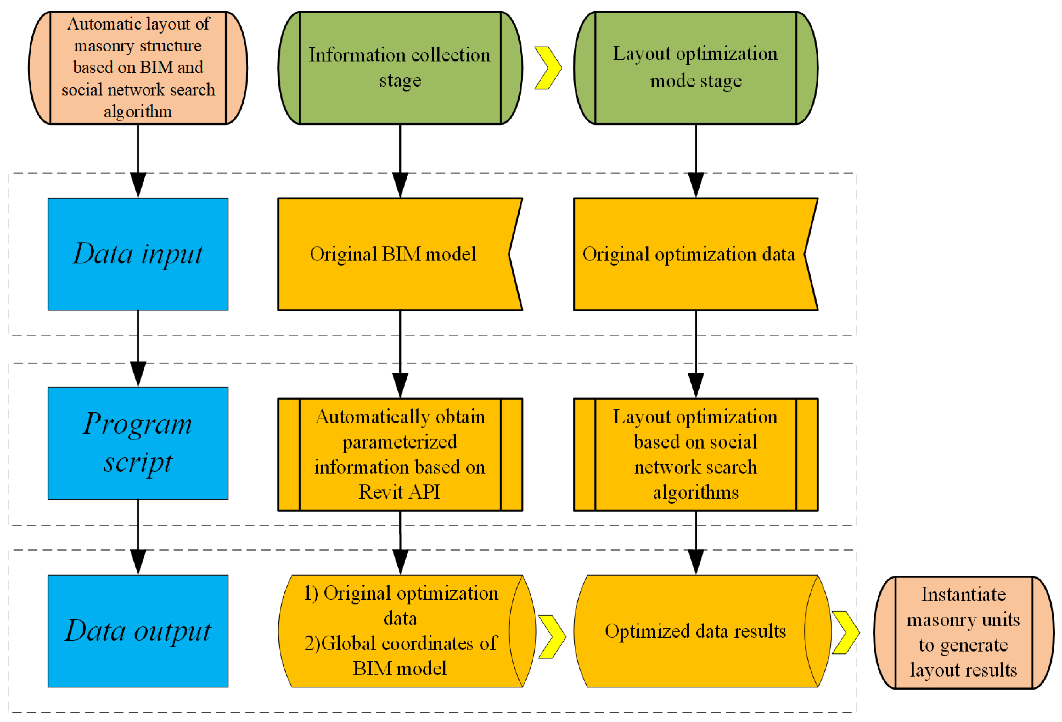
A systematic framework achieves automated masonry block layout and optimization through two core phases:
  • Phase 1: Information Acquisition;
  • Phase 2: Layout Optimization.
The framework enables bidirectional data exchange between physical models and computational datasets via BIM APIs. It utilizes intelligent algorithms for decision support, decodes optimized data, and instantiates MUs. This process achieves automated masonry layout. Figure 4 illustrates the implementation workflow.

3.1. Information Collection Stage

3.1.1. BIM Software Selection

The framework’s data collection module implements C#-based secondary development utilizing Autodesk Revit’s API. Autodesk Revit provides a parametric modeling platform embedding relational logic between elements for coordinated change management [36]. However, masonry wall modeling remains complex and labor-intensive. Native Revit functionality proves insufficient for rapid, precise brick cutting and placement. Secondary development via Revit API resolves this limitation. The Revit API serves as a universal interface enabling C# application integration by users and developers. Revit-C# integration establishes efficient masonry layout optimization.

3.1.2. Extract Parametric Information from the BIM Model

The Information Collection Module extracts parametric masonry models from Revit, using BIM models as data carriers to acquire essential optimization parameters: wall dimensions, spatial coordinates, and unit specifications.
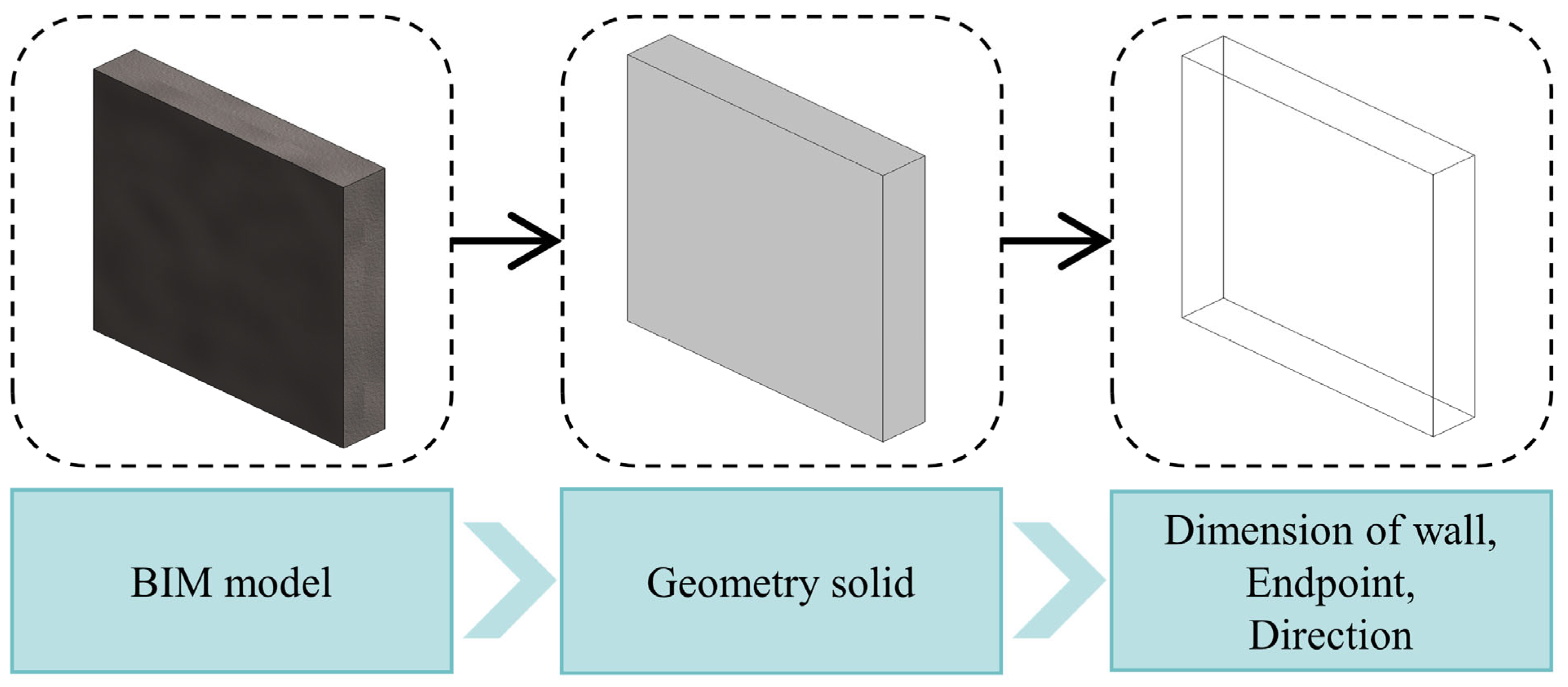
Revit API provides geometry processing capabilities. Wall geometric data resides in Solid entities. Figure 5 illustrates how wall geometry (Solid) is retrieved via the “Geometry” property. Solid entities contain all geometric faces and edges, enabling derivation of endpoints and directional vectors.
These attributes enable extraction of critical parameters: wall length, height, thickness, and reference point positions in Revit global coordinates. Geometric parameters serve as inputs for layout optimization, while spatial coordinates provide placement references.

3.2. Layout Optimization Stage

A computational module determines optimal brick layout parameters for subregion optimization. This process utilizes data collected by the information acquisition module, performing non-modular wall layout adjustments by:
  • Modifying the quantity of full bricks;
  • Cutting coordination bricks;
  • Adjusting joint thicknesses.
The computation considers adaptability in both horizontal and vertical orientations while satisfying boundary constraints. An additional fitness function was implemented to minimize material waste from brick cutting.

3.2.1. Two-Dimensional Bin Packing Problem

This research models masonry wall layout optimization as a Two-Dimensional Bin Packing Problem (2D-BP). MUs represent rectangular items with defined dimensions, while wall models function as rectangular containers. Solutions must satisfy masonry specifications under standard 2D-BP constraints to maximize space utilization.
Placed MUs become obstacles for subsequent optimization, requiring:
Non-overlapping placement;
Edges parallel to container boundaries.
This 2D-BP solution yields masonry unit layout schemes. The 2D-BP extends the 1D bin packing problem geometrically. This NP-Hard problem packs item set A = r i w i , h i | i = 1,2 , , n into bins to maximize filled area under:
All edges parallel to bin boundaries without exceeding them;
Non-overlapping placement without rotation.
While MUs possess three-dimensional geometry, their thickness remains irrelevant to wall layout optimization. Consequently, masonry layout problems reduce to computationally complex two-dimensional optimization domains. To address the unique characteristics of masonry arrangements, this study employs a stratified layout approach (Figure 6) for solving the 2D bin packing problem.
Each container layer corresponds to a brick course in this methodology. The process operates through two sequential phases: initially packing rectangular items into horizontal layers, then progressively filling each layer to complete containers. This stratified strategy simultaneously satisfies masonry bonding requirements and reduces computational complexity.

3.2.2. Layout Model

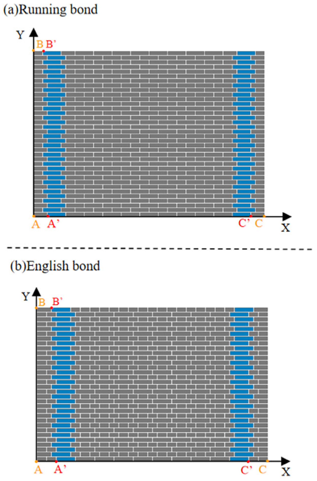
To precisely position MUs, their 3D representations are abstracted into 2D models defining wall-relative positions. A Cartesian coordinate system is established on the wall substrate with origin at the bottom-left vertex: X-axis along the bottom edge (length L), Y-axis along the left edge (height H).
Per geometric principles, control points are defined at planar edge intersections: origin A ( X A , Y A ) , top-left vertex B ( X B , Y B ) , and bottom-right vertex C ( X C , Y C ) . Brick arrangements at wall terminals follow bonding patterns:
Running Bond: Three-quarter bats (odd courses) and headers (even courses);
English Bond: Dual parallel headers (odd courses) and three-quarter bats (even courses).
Control points are offset to locate coordination bricks:
  • A A ( X A , Y A ) : Bottom-left coordination brick;
  • B B ( X B , Y B ) : Top-left coordination brick;
  • C C ( X C , Y C ) : Bottom-right coordination brick.
The resulting 3D coordinate system is illustrated in Figure 7.

3.2.3. Decision Variable

Masonry layout aims to integrate units and mortar into robust, stable structures while satisfying constraints governed by design standards, construction requirements, wall dimensions, bonding patterns, and unit sizes. Key decision variables for bonding methods are detailed below.
In masonry layouts, course height H c comprises unit height H u and horizontal joint thickness H j . While bonding patterns vary, H u remains constant. Vertical layout optimization adjusts H j and course quantity N c . All horizontal joints require uniform thickness adjustment within the range specified in Section 3.2.1 for mortar joint standards.
The horizontal joint thickness χ 1 ranges between 8   m m χ 1 12   m m . The number of courses χ 2 depends on the ratio of wall height Hw to brick height Hb, thus χ 2 satisfies 0 χ 2 i n t ( H w H b ) .
As brick wall layout is repetitive, optimization focuses solely on odd and even courses. Vertical joint thickness dl remains fixed at the optimal value. Coordination brick length χ 3 ranges from brick width to length: w b χ 3 l b . The quantities of full bricks in odd/even courses ( χ 4 , χ 5 ) are determined by the ratio of wall length l w to brick length L b . Since brick counts must be integers, χ 4 , χ 5 [ 0 , int ( L w L b ) ] Ζ .
Continuous variables in brick layout optimization are discretized via Gaussian rounding. Specifically, each variable yields two potential integer values after processing, with Gaussian operation selecting the nearest integer as defined by Formula (1).
X = x , 0 x x < 0.5 x , 0 x x < 1

3.2.4. Fitness Function

Based on the problem’s objectives and constraints, a penalty function is constructed to form the vertical fitness function.
Odd-course layouts must satisfy wall length constraints, minimizing the distance between horizontally arranged brick length and wall length L w . The corresponding penalty function P 1 is defined in Formula (5).
X C = X A + 2 x 3 + d l + x 4 l b + d l d l
X C = X C + l f
X A = l f
P 1 ( x ) = ( L W X C ) 2
Even-course layouts must similarly satisfy wall length constraints, with penalty function P 2 given in Formula (7).
G = 2 l f + 2 x 3 + d l + x 5 k b + d l d l
P 2 ( x ) = ( L W G ) 2
Note: k b = l b for Running Bond; k b = l b for English Bond.
Brick layouts must comply with wall height constraints, minimizing the distance between vertically stacked brick height and wall height H w . Penalty function P 3 is specified in Formula (10).
Y B = Y A + ( h w + x 1 ) x 2 + x 1
Y B = Y A + x 1
P 3 x = H w Y B 2
Material waste reduction requires minimizing course counts. Penalty function P 4 is defined in Formula (11).
P 4 ( x ) = x 2
Joint thickness should approximate optimal thickness l j . Penalty function P 5 is given in Formula (12).
P 5 ( x ) = ( x 1 l j ) 2
The x-coordinates X A , X B , X C correspond to points A , B , C , while Y A , Y B , Y C denote their y-coordinates; l b is brick length, w b brick width, h w brick height, and l b three-quarter bat length. End brick length l f is configured as follows:
  • Three-quarter bat ends: l f = l b + d l ;
  • Dual-header ends: l f = 2 ( w b + d l ) ;
  • Single-header ends: l f = w b + l b + 2 d l .
For the vertical multi-objective model with inconsistent dimensions, Max-Min normalization (Formula (13)) eliminates dimensionality before constructing the fitness function.
Linear weighting of multi-objective problems into a single-objective formulation represents a prevalent approach in optimization methodologies. This study employs the linear weighting method to aggregate five objective functions P into a unified fitness function for masonry wall layout optimization, as formalized in Equation (14).
P P i = P i min P i max P i min P i
M i n i n z e F = i = 1 5 ω i P P i ( x )
i = 1 5 ω i = 1
where ω i > 0 denotes the weight coefficients.
Fifteen masonry engineering experts were invited to evaluate five criteria using the 1–9 importance scale. Their assessments were consolidated into judgment matrix C1 (Table 2). The eigenvalue method yielded the weight vector ω i = (0.3621, 0.3621, 0.1607, 0.0389, 0.0762), with consistency metrics R = 5.1361, CI = 0.0340, and CR = 0.0306. As CR < 0.1, matrix C1 passes the consistency test.

3.2.5. Layout Solution for the SNS

This study addresses masonry wall layout optimization as a two-dimensional bin packing problem. Current solution approaches comprise three algorithmic categories: exact algorithms, heuristics, and metaheuristics. Exact algorithms guarantee optimal solutions but necessitate exhaustive searches across all configurations, becoming computationally prohibitive for large-scale masonry walls with high unit counts. Heuristic algorithms rapidly generate approximate solutions yet frequently converge to local optima with significant solution uncertainty [37]. Metaheuristics enhance heuristic methods by integrating stochastic processes with local search mechanisms, extending exploration from local to global optimization. For masonry layout problems, metaheuristics demonstrate enhanced computational efficiency.
The SNS algorithm is a novel metaheuristic optimization method that simulates human–social interactions [38]. In this paradigm, each user’s viewpoint represents a candidate solution, while social behaviors—imitation, dialogue, disputation, and innovation—function as algorithmic operators that continuously generate new solutions. Compared to conventional methods (Table 3), SNS demonstrates enhanced accuracy in solving large-scale masonry layout problems. It efficiently identifies near-optimal solutions for complex, high-volume unit arrangements through enhanced optimization efficiency and accelerated convergence [39].
In solving masonry wall layout problems, each solution set is randomly initialized within the search boundaries of five fundamental variables defined in Section 3.2.2 (Equation (16)). The masonry wall structure is modeled by solution vector X i = { x 1 , x 2 , x 3 , x 4 , x 5 } , where i denotes the i-th solution.
X 0 = L B + r a n d ( U B L B )
where L B is the lower bound, U B the upper bound, and rand a random number in [0,1].
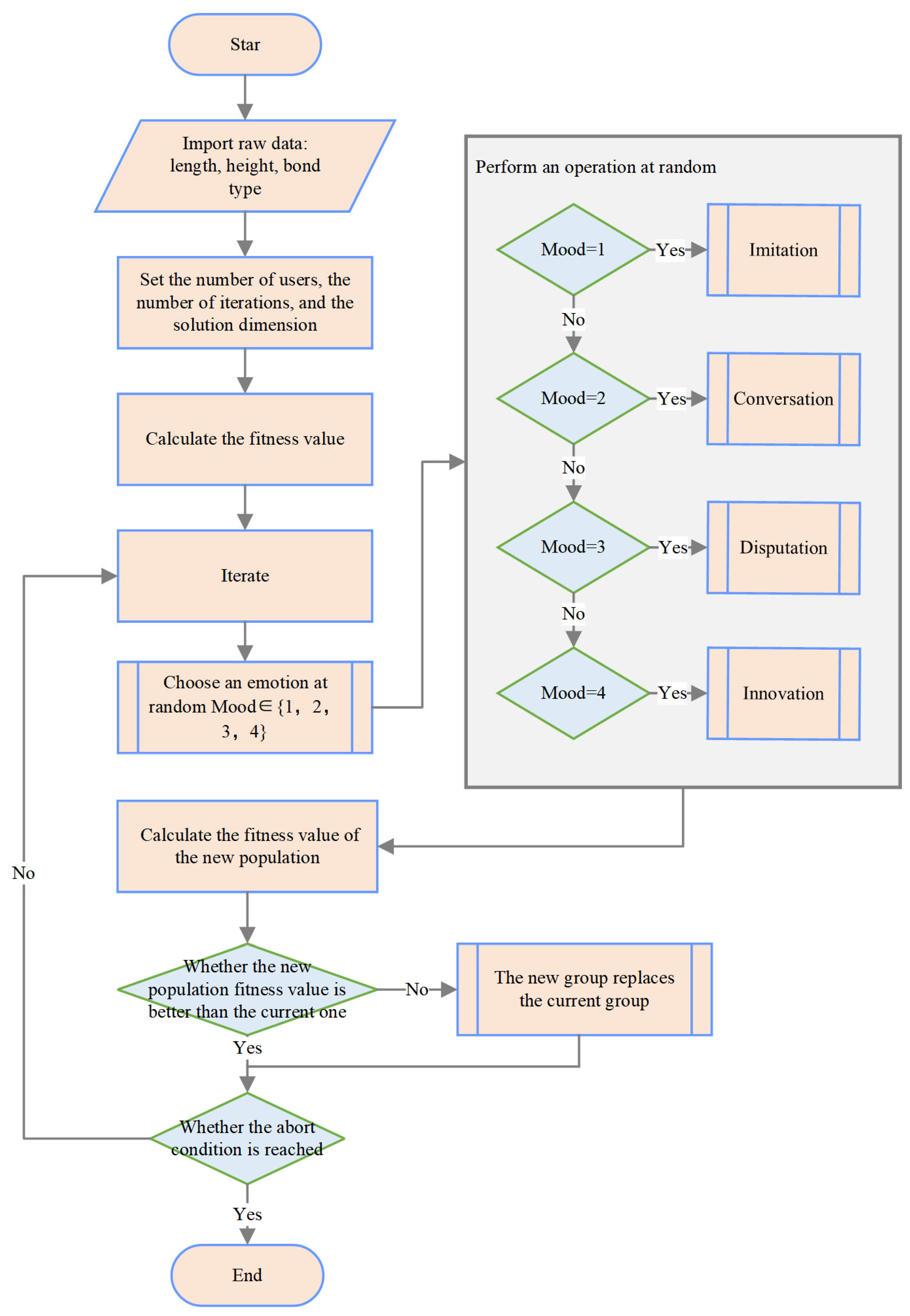
During computation, new solutions are generated by operators corresponding to real-world social moods. SNS randomly selects an integer between 1 and 4 before updating solutions, with each integer representing a specific mood operator. Each solution stochastically adopts one operator to update its layout configuration.
(1) Imitation Behavior (Formula (17)): When influencers post new activities, most users imitate their behavior.
X i n e w = X j + r a n d ( 1,1 ) R R = r a n d ( 0,1 ) r r = X j X i
where i, j denote distinct users (ij), R is the influence level of user j, R represents popularity of user j, and X i , X j are randomly selected conversational partners.
(2) Dialogue Behavior (Formula (18)): Users engage in virtual interactions to discuss topics.
X i n e w = X k + R R = r a n d ( 0,1 ) D D = s i g n ( f i f j ) ( X j X i )
where X k is a randomly chosen third user (kij), R is the imitation effect, D is viewpoint divergence, and f i , f j are fitness values of individuals i and j.
(3) Disputation Behavior (Formula (19)): Users defend their viewpoints while considering opposing perspectives.
X i n e w = X i + r a n d ( 0,1 ) ( M A F X i ) M = r N r X t N r A F = 1 + r o u n d ( f a n d )
where M is the mean opinion in comment sections or fan communities, and AF (Approval Factor, 0 or 1) indicates agreement level.
(4) Innovation Behavior (Formula (20)): Novel viewpoints emerge by altering conceptual features.
X i , n e w d = t X j d + ( 1 t ) n n e w d n n e w d = l b d + r a n d 1 ( u b d l b d ) t = r a n d 2
where d is a randomly selected dimension, r a n d 1 , r a n d 2 ∈ [0,1], and u b d , l b d d are dimension bounds.
Based on the minimization principle of the objective function, if a newly generated solution outperforms the current solution, it replaces the current solution. The algorithm then checks termination conditions; if unmet, it proceeds to the next iteration until conditions are satisfied, outputting the optimal solution. The algorithm flow is shown in Figure 8.

4. Case Analysis and Discussion

This section verifies the effectiveness and practicality of the proposed framework through experimental validation. Section 4.1 details the experimental parameters, while Section 4.2 establishes three case studies: masonry corners with three geometric configurations, walls containing openings, and a full-scale architectural case to comprehensively test the methodology.

4.1. Experimental Configuration and Parameters

This study utilized Revit for BIM modeling, with automation implemented via C# API calls. Experiments employed standard cement bricks (190 mm × 90 mm × 40 mm), optimal joint thickness of 10 mm, following both Running Bond and English Bond patterns. Algorithm parameters included 50 initial users, 300 maximum iterations, and uniform 0.25 selection probabilities for imitation, dialogue, disputation, and innovation operators, with stochastic selection per iteration. Computations were executed on an Intel® (Santa Clara, CA, USA) Core™ i7-10750H processor (2.60 GHz, 6 cores) with 16.0 GB RAM under Windows 10 64-bit OS.

4.2. Framework Test Case

4.2.1. Layout Experiment with Corner Areas Included

Case Study 1 investigated continuous walls with corner joints to validate subregion integration. Three joint typologies were evaluated:
  • L-shaped corners (Type a);
  • T-shaped corners (Type b);
  • Cross-shaped corners (Type c).
Wall dimensions (Table 4) varied within length ranges of 2000–4400 mm and height ranges of 2000–3000 mm. Each configuration underwent combinatorial connection testing to validate layout adaptability across joint types.
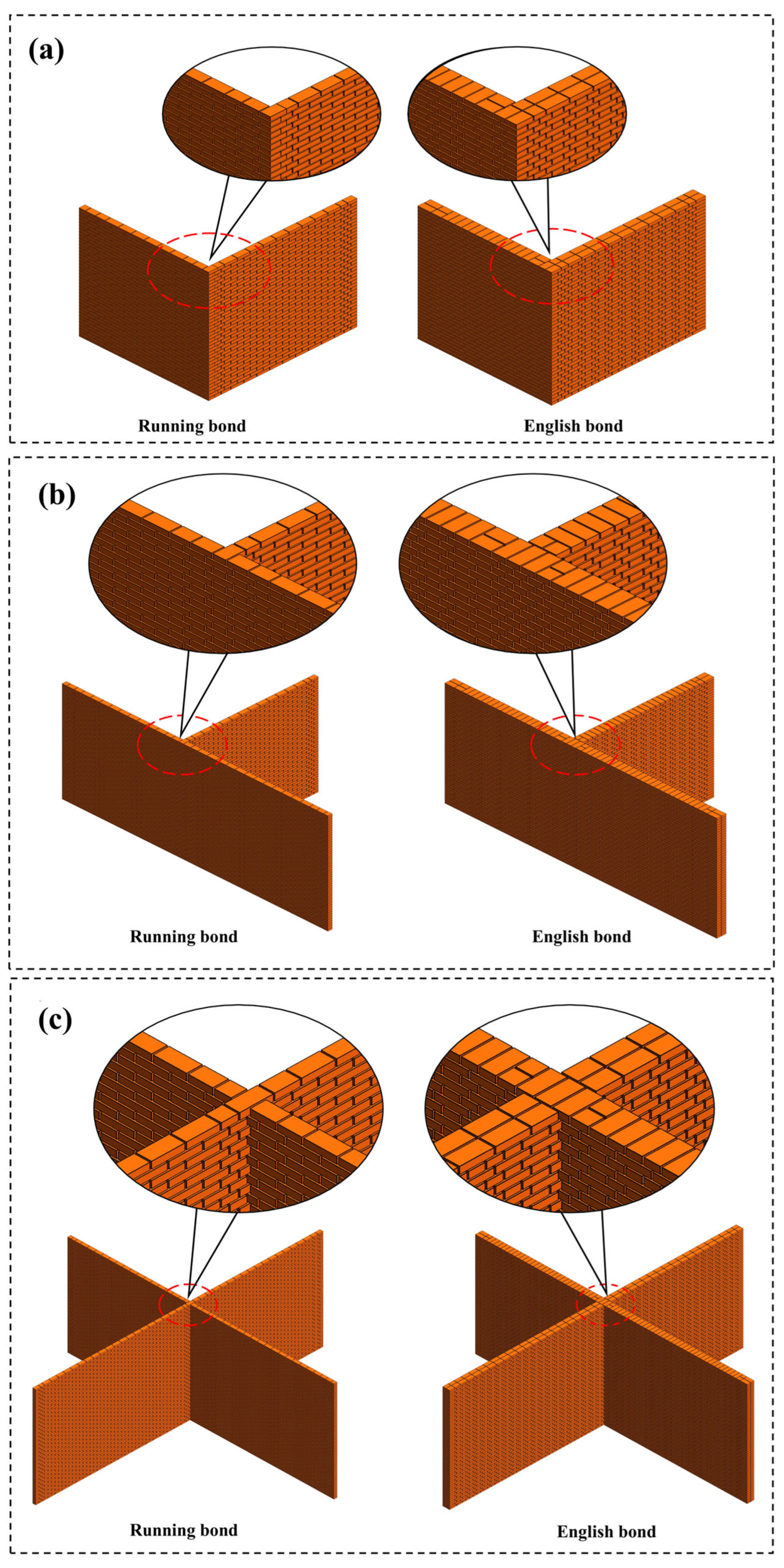
The original BIM model is shown in Figure 9. Based on wall connection types, Case (a) was divided into two computational regions, Case (b) into three regions, and Case (c) into four regions. The prototype system converted BIM geometric data into optimization inputs while recording wall position coordinates, automatically generating layout results. As demonstrated in Figure 10, brick arrangements under both Running Bond and English Bond patterns satisfied two critical criteria across all nine wall assemblies: strict adherence to staggered joint requirements within wall boundaries, and maintenance of staggered lap lengths at junction zones enabling structural continuity.
The system achieved non-modular layouts while ensuring structurally sound corner joint connections.
The production efficiency of the proposed framework was evaluated against time-consuming manual modeling. Each case was executed five times independently, with average runtimes recorded in Table 5. Since the SNS algorithm decomposes wall layouts into five key points (fixed-dimensional solution space), computational time remains unaffected by wall dimensions but scales with subregion count. Notably, English Bond layouts required marginally longer processing than Running Bond due to higher brick quantities, which increased Revit instance placement time.
Professional BIM engineers manually created Cases (a), (b), and (c) for benchmarking. Comparative analysis revealed two key advantages:
  • 93% Time Reduction: Manual layout exceeded 5 min per case, while the framework achieved near-instant generation;
  • Performance Optimization: Manual array operations caused model lag, whereas prototype-generated brick instances ensured seamless operation.

4.2.2. Layout Experiment Including Wall Openings

Case Study 2 examined walls with door/window openings, including:
  • Instance (a): Wall length 4000 mm, height 3000 mm, containing a 1500 × 2100 mm door opening with bottom edge flush to wall base;
  • Instance (b): Identical wall dimensions with a 1200 × 1300 mm window opening elevated 900 mm from the base.
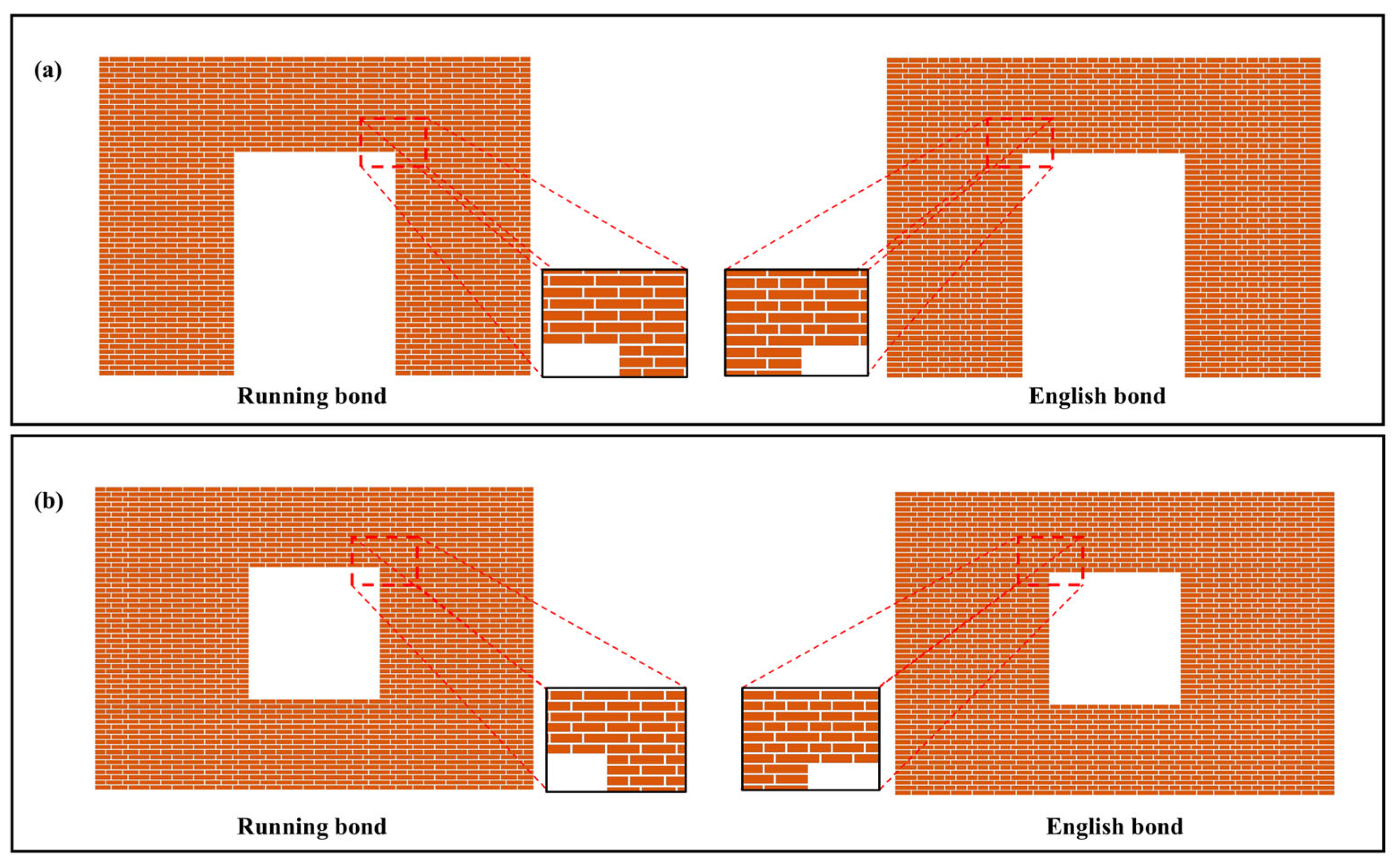
The proposed framework automated layouts using vertical segmentation (Figure 11), dividing Instance (a) into three regions and Instance (b) into four. Final layouts (Figure 12) demonstrate that vertical partitioning—unlike Xu et al.’s horizontal approach—prevents vertical mortar joint misalignment at region interfaces [33]. By applying the layout strategy from Section 2.2, subregions combined seamlessly while maintaining opening dimensions identical to original BIM specifications.

4.2.3. Building Case

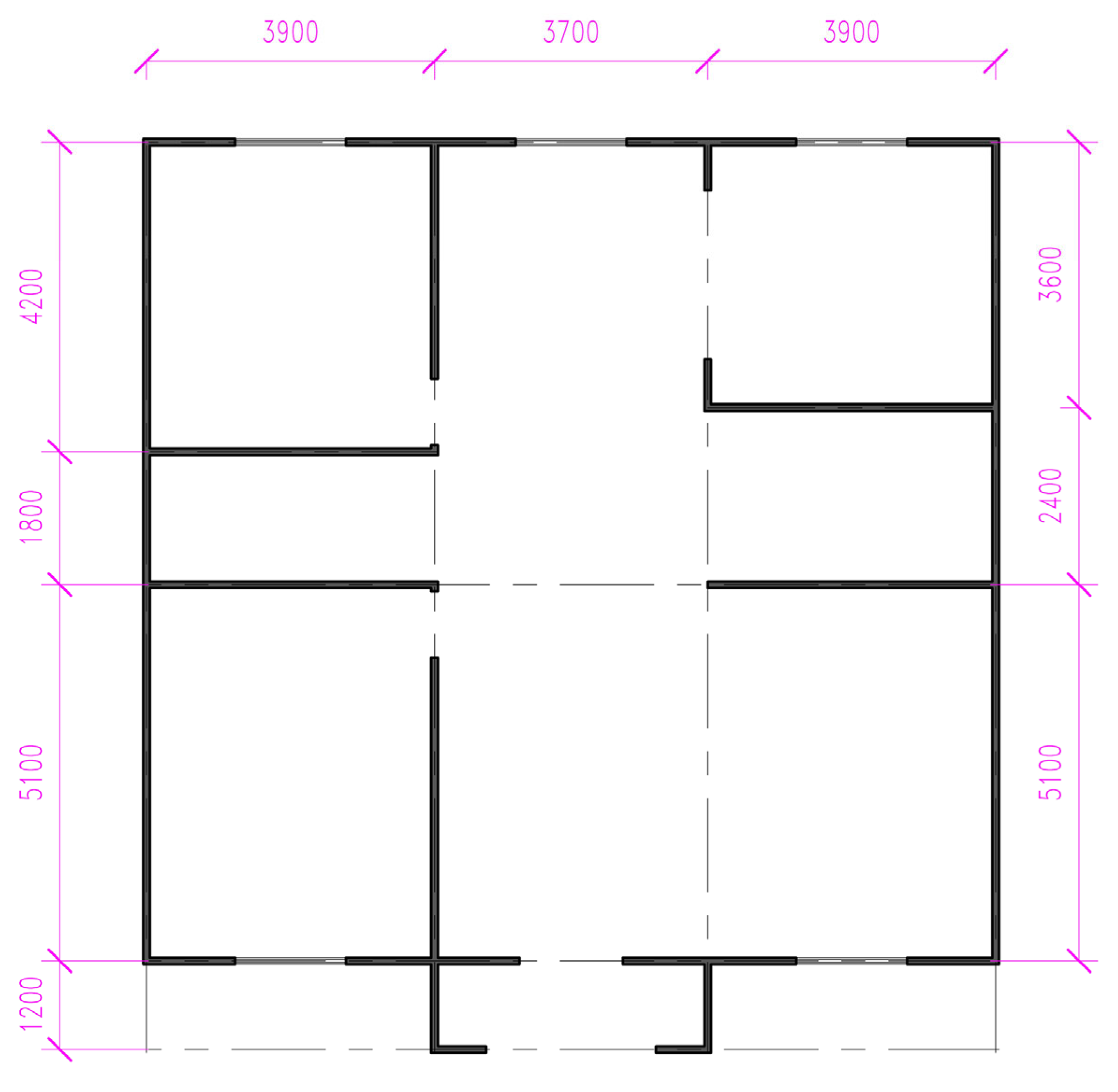
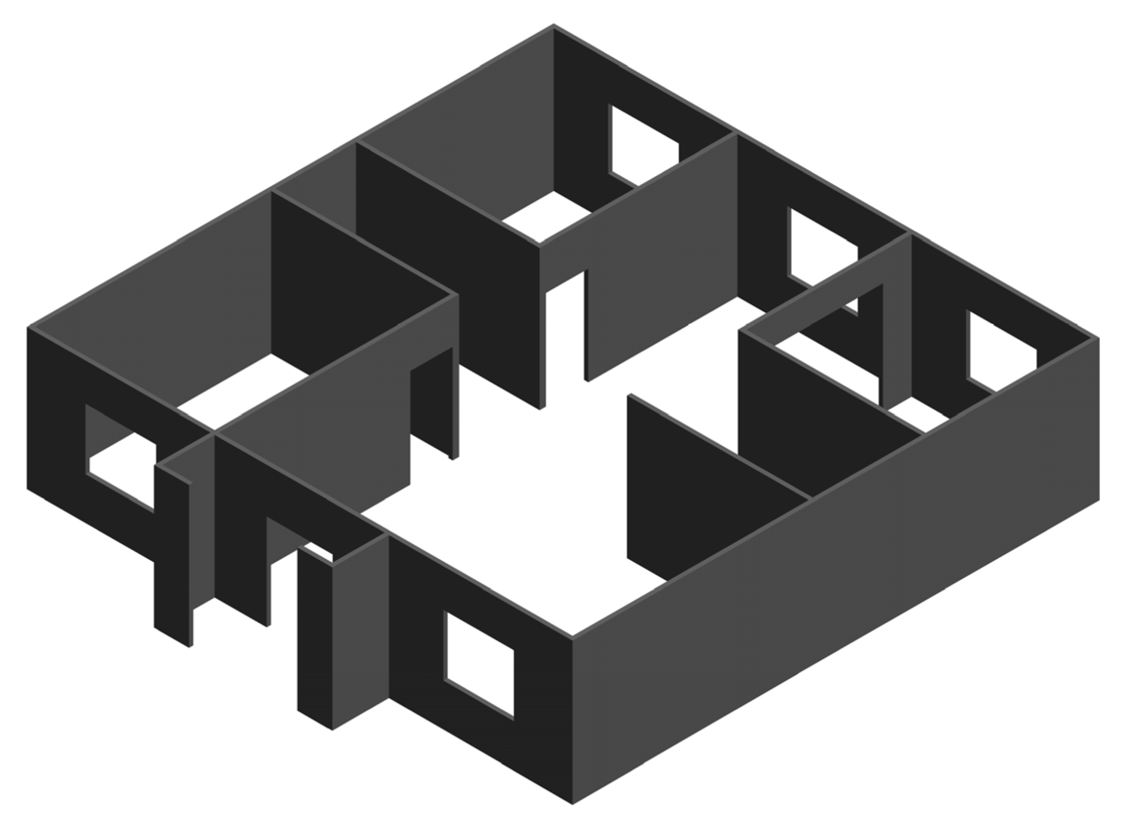
Case Study 3 analyzed an architectural case study of a residential building’s ground floor, characterized by complex architectural form and wall geometries with sufficient detail granularity. The 2D design drawings (Figure 13) feature walls of varying dimensions with 3000 mm free-standing height, incorporating L-shaped, T-shaped, and cross-shaped corners alongside door/window openings. The Revit-based 3D BIM model is shown in Figure 14.
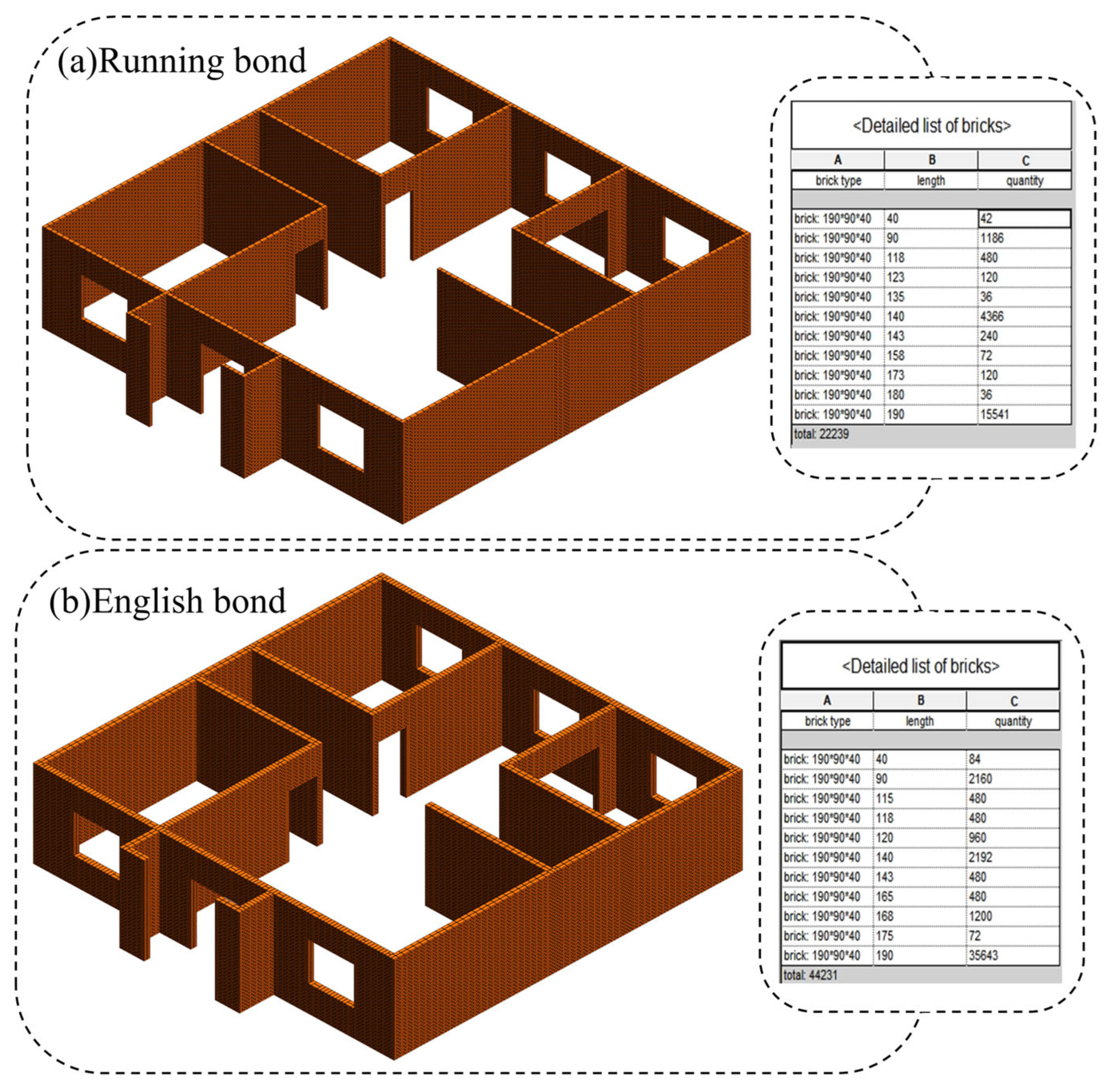
The proposed framework generated masonry layouts by partitioning 23 walls into 44 subregions based on corner/opening configurations. Layout results (Figure 15) were automatically produced by the prototype system, exhibiting zero instances of vertical mortar joint misalignment or boundary-exceeding bricks. Furthermore, the framework incorporates real-world masonry standards and bricklaying practices, enhancing solution quality and practical applicability.
By utilizing the schedule function, precise brick quantity data for the building can be obtained to generate accurate procurement information. In practical projects, engineers typically estimate brick consumption through theoretical calculations using Formula (21).
N = S K r B r l + d B r h + d
where S denotes the wall area requiring bricklaying, K is the coefficient determined by the ratio of wall thickness to brick thickness, B r l represents the brick length used in the area, B r h is the brick height dimension affecting consumption, d indicates mortar joint thickness, and r is the cutting loss coefficient for non-modular walls.
Calculation results for the residential case study indicate that Running Bond requires 22,008 bricks theoretically, while English Bond requires 44,016 bricks. The scheduling system prioritizes sourcing sub-90 mm bricks from cutting waste, with 90 mm half-bricks obtained by splitting full bricks. Actual consumption after optimization totals 21,604 bricks for Running Bond (1.87% reduction) and 43,067 bricks for English Bond (2.2% reduction). Compared to traditional estimation methods, the proposed framework not only provides precise procurement and cutting data but also effectively reduces material consumption. Procurement teams can utilize accurate brick quantities from schedules for purchasing, while construction crews and supervisors execute masonry works using optimized layouts adapted to actual site conditions.

5. Conclusions

This study proposes a BIM-based secondary development system for automated masonry layout, designed to efficiently complete masonry structural designs while preventing material waste and rework caused by improper on-site cutting. The system integrates professional knowledge of brick cutting, arrangement, and planning with computational algorithms, utilizing C# to call Revit API for optimized masonry layouts. Validation was performed through four specialized masonry zones and one architectural case study.
The research contributions are as follows:
(1)
The proposed optimization framework achieves standardized and aesthetically coherent brick layouts for individual walls, interconnected wall junctions, and openings (doors/windows) in common special sections;
(2)
Rapid parametric modeling of masonry walls significantly reduces repetitive tasks, improving modeling efficiency by over 93% compared to manual methods. All test cases generated masonry models within 30 s through instantiation of brick families;
(3)
By optimizing masonry wall layouts, the system rationally plans brick usage, reducing consumption by 1.87% (Running Bond) and 2.2% (English Bond) compared to conventional budgeting. It provides precise cutting specifications and procurement data;
(4)
Abstracting masonry layout into a 2D bin packing problem with domain-specific constraints, this work pioneers rectilinear wall optimization strategies and masonry layout models. This demonstrates practical engineering applications of 2D bin packing theory and offers solutions for tile, formwork, and curtain wall layouts;
(5)
The innovative integration of intelligent optimization algorithms with C# programming enables cross-platform collaboration, advancing civil engineering-computer science convergence and supporting intelligent construction transformation.
However, the developed automated masonry layout methodology exhibits the following limitations:
(1)
This study is currently limited to two common bond patterns (Running Bond and English Bond), rectilinear walls, and single-size MUs. Further research is required to optimize layouts incorporating diverse MUs, construction techniques, and wall geometries encountered in actual engineering practice;
(2)
The methodology adheres strictly to China’s masonry construction codes (GB 50924-2014), resulting in distinct regional characteristics. Subsequent research should extend this approach to accommodate international masonry standards;
(3)
The mathematical model prioritizes minimizing MU consumption and achieving uniform mortar joint thickness within code-compliant constraints derived from empirical construction practices. While the metaheuristic algorithm delivers near-optimal solutions within acceptable engineering tolerances, future work should integrate advanced computational strategies to pursue exact solutions for enhanced precision.

Author Contributions

Conceptualization, L.J.; methodology, L.J.; software, R.Y.; validation, T.Q.; investigation, W.L. and Z.L.; writing—original draft, L.J.; writing—review and editing, T.Q., L.J., R.Y., W.L. and Z.L.; visualization, W.L.; formal analysis, T.Q. and R.Y.; supervision, Z.L.; funding acquisition, W.L. All authors have read and agreed to the published version of the manuscript.

Funding

This research was funded by the Science and Technology Plan Project of Jiangxi Geological Bureau, grant number 2023JXDZKJKY07, the Science and Technology Plan Project of Jiangxi Geological Bureau grant number 2021JXDZ70001; and the Science and Technology Plan Project of Jiangxi Coalfield Geology Bureau, grant number 2020JXMD70003.

Data Availability Statement

Upon formal request and subject to compliance with ethical guidelines, confidentiality agreements, and intellectual property regulations, the complete research datasets, computational models, and algorithm source code developed in this study will be made available through secure institutional repositories.

Conflicts of Interest

Authors Weizhen Lu and Zhongcun Liu were employed by the company ZhongMei Engineering Group Ltd. The remaining authors declare that the research was conducted in the absence of any commercial or financial relationships that could be construed as a potential conflict of interest.

References

  1. Xu, Y.; Wang, J.; Yang, Z. Generic goal-oriented design for layout and cutting of floor tiles. Autom. Constr. 2023, 152, 104903. [Google Scholar] [CrossRef]
  2. Majerska-Pałubicka, B.; Latusek, E. Intelligence-Based Design Illustrated with Examples of ACROS Fukuoka, KKL Luzern and MICA Changsha Buildings—A Multicriterial Case Study. Buildings 2021, 11, 135. [Google Scholar] [CrossRef]
  3. Emad, S.; Aboulnaga, M.; Wanas, A.; Abouaiana, A. The Role of Artificial Intelligence in Developing the Tall Buildings of Tomorrow. Buildings 2025, 15, 749. [Google Scholar] [CrossRef]
  4. Chen, Y.; Wang, X.; Liu, Z.; Cui, J.; Osmani, M.; Demian, P. Exploring Building Information Modeling (BIM) and Internet of Things (IoT) Integration for Sustainable Building. Buildings 2023, 13, 288. [Google Scholar] [CrossRef]
  5. D’aLtri, A.M.; Sarhosis, V.; Milani, G.; Rots, J.; Cattari, S.; Lagomarsino, S.; Sacco, E.; Tralli, A.; Castellazzi, G.; de Miranda, S. Modeling Strategies for the Computational Analysis of Unreinforced Masonry Structures: Review and Classification. Arch. Comput. Methods Eng. 2020, 27, 1153–1185. [Google Scholar] [CrossRef]
  6. Zhang, P.; Chen, L.; Wei, T.; Huang, P.; Wang, H.; Chen, X. Multi-Hazard Assessment of Masonry Buildings: A State-of-the-Art Review. Buildings 2024, 14, 3711. [Google Scholar] [CrossRef]
  7. Gambao, E.; Balaguer, C.; Gebhart, F. Robot assembly system for computer-integrated construction. Autom. Constr. 2000, 9, 479–487. [Google Scholar] [CrossRef]
  8. Linares-Garcia, D.A.; Roofigari-Esfahan, N.; Pratt, K.; Jeon, M. Voice-Based Intelligent Virtual Agents (VIVA) to Support Construction Worker Productivity. Autom. Constr. 2022, 143, 104554. [Google Scholar] [CrossRef]
  9. Lyu, S.; Zhu, Q.; Hu, X.; Zhu, Z.; Skitmore, M. Migrant Workers in the Construction Industry: A Bibliometric and Qualitative Content Analysis. Buildings 2025, 15, 761. [Google Scholar] [CrossRef]
  10. Zhu, L.; Zhu, Z.; Delgado, J.M.P.Q. Reuse of Clay Brick Waste in Mortar and Concrete. Adv. Mater. Sci. Eng. 2020, 2020, 6326178. [Google Scholar] [CrossRef]
  11. Nath, A.J.; Lal, R.; Das, A.K. Fired Bricks: CO2 Emission and Food Insecurity. Glob. Chall. 2018, 2, 1700115. [Google Scholar] [CrossRef]
  12. Brooks, N.; Biswas, D.; Hossin, R.; Yu, A.; Saha, S.; Saha, S.; Saha, S.K.; Luby, S.P. Health consequences of small-scale industrial pollution: Evidence from the brick sector in Bangladesh. World Dev. 2023, 170, 106318. [Google Scholar] [CrossRef]
  13. Zhang, X.; Zheng, R. Reducing building embodied emissions in the design phase: A comparative study on structural alternatives. J. Clean. Prod. 2020, 243, 118656. [Google Scholar] [CrossRef]
  14. Seeboo, A. Designing out waste by optimizing floor layout with locally available building materials. J. Clean. Prod. 2022, 332, 130006. [Google Scholar] [CrossRef]
  15. Liu, H.; Singh, G.; Lu, M.; Bouferguene, A.; Al-Hussein, M. BIM-based automated design and planning for boarding of light-frame residential buildings. Autom. Constr. 2018, 89, 235–249. [Google Scholar] [CrossRef]
  16. Yardimci, Y.; Kurucay, E. LCA-TOPSIS Integration for Minimizing Material Waste in the Construction Sector: A BIM-Based Decision-Making. Buildings 2024, 14, 3919. [Google Scholar] [CrossRef]
  17. Liu, J.; Cao, Y.; Xue, Y.; Li, D.; Feng, L.; Chen, Y.F. Automatic unit layout of masonry structure using memetic algorithm and building information modeling. Autom. Constr. 2021, 130, 103858. [Google Scholar] [CrossRef]
  18. Cavieres, A.; Gentry, R.; Al-Haddad, T. Knowledge-based parametric tools for concrete masonry walls: Conceptual design and preliminary structural analysis. Autom. Constr. 2011, 20, 716–728. [Google Scholar] [CrossRef]
  19. Hong, Y.; Hammad, A.W.; Nezhad, A.A. Optimising the implementation of BIM: A 2-stage stochastic programming approach. Autom. Constr. 2022, 136, 104170. [Google Scholar] [CrossRef]
  20. Wang, J.; Ma, Y.; Li, R.; Zhang, S. Applications of Building Information Modeling (BIM) and BIM-Related Technologies for Sustainable Risk and Disaster Management in Buildings: A Meta-Analysis (2014–2024). Buildings 2025, 15, 2289. [Google Scholar] [CrossRef]
  21. Koseoglu, O.; Keskin, B.; Ozorhon, B. Challenges and Enablers in BIM-Enabled Digital Transformation in Mega Projects: The Istanbul New Airport Project Case Study. Buildings 2019, 9, 115. [Google Scholar] [CrossRef]
  22. Lim, Y.-W. Building Information Modeling for Indoor Environmental Performance Analysis. Am. J. Environ. Sci. 2015, 11, 55–61. [Google Scholar] [CrossRef]
  23. Chen, P.-H.; Nguyen, T.C. A BIM-WMS integrated decision support tool for supply chain management in construction. Autom. Constr. 2019, 98, 289–301. [Google Scholar] [CrossRef]
  24. Arenas, N.F.; Shafique, M. Recent progress on BIM-based sustainable buildings: State of the art review. Dev. Built Environ. 2023, 15, 100176. [Google Scholar] [CrossRef]
  25. Abdelmoti, A.M.; Shafiq, M.T.; Rauf, A.; Khalfan, M.M.A. Challenges in Asset Management and Digital Twins: Industry Insights. Buildings 2025, 15, 1809. [Google Scholar] [CrossRef]
  26. Yin, H.; Liu, J.; Liu, M.; Li, X. Research on BIM Technology of Green Building Based on GBSWARE Software. Buildings 2025, 15, 2297. [Google Scholar] [CrossRef]
  27. Li, L.; Gao, L.; Zhang, X.; Xu, H.; Jiang, L. Research on Building’s Carbon Emission Calculation and Reduction Strategy Based on Life Cycle Assessment (LCA) and Building in Formation Modeling (BIM): A Case Study in Beijing, China. Buildings 2025, 15, 1403. [Google Scholar] [CrossRef]
  28. Goessens, S.; Mueller, C.; Latteur, P. Feasibility study for drone-based masonry construction of real-scale structures. Autom. Constr. 2018, 94, 458–480. [Google Scholar] [CrossRef]
  29. Monteiro, A.; Ferreira, R.C.; Santos, E.T. Representation paradigms for masonry modulation in BIM tools. Gestão Tecnol. Proj. 2009, 4, 54–75. [Google Scholar] [CrossRef]
  30. Sharif, S.; Elder, J. Masonry Unit Database Development for BIM-Masonry. In Proceedings of the 12th North American Masonry Conference, Denver, CO, USA, 17–20 May 2015; Available online: https://www.academia.edu/14129421/Masonry_Unit_Database_Development_for_BIM_Masonry (accessed on 25 June 2025).
  31. Cavieres, A.; Gentry, R. Masonry Regions: A New Approach for the Representation of Masonry Walls in BIM Applications. In Proceedings of the eCAADe 2015: Real Time—Extending the Reach of Computation, Vienna, Austria, 16–18 September 2015. [Google Scholar] [CrossRef]
  32. Zaki, T.; Nassar, K.; Hosny, O. Parametric Blockwall-Assembly Algorithms for the Automated Generation of Virtual Wall Mockups Using BIM. In Proceedings of the Architectural Engineering Conference 2017, Oklahoma City, OK, USA, 11–13 April 2017; pp. 844–854. [Google Scholar] [CrossRef]
  33. Xu, C.; Liu, J.; Li, S.; Wu, Z.; Chen, Y.F. Optimal brick layout of masonry walls based on intelligent evolutionary algorithm and building information modeling. Autom. Constr. 2021, 129, 103824. [Google Scholar] [CrossRef]
  34. Hendry, E.A. Masonry walls: Materials and construction. Constr. Build. Mater. 2001, 15, 323–330. [Google Scholar] [CrossRef]
  35. Zucchini, A.; Lourenço, P. A micro-mechanical model for the homogenisation of masonry. Int. J. Solids Struct. 2002, 39, 3233–3255. [Google Scholar] [CrossRef]
  36. Yang, X.; Koehl, M.; Grussenmeyer, P. Parametric modelling of as-built beam framed structure in BIM environment. ISPRS-Int. Arch. Photogramm. Remote Sens. Spat. Inf. Sci. 2017, XLII-2/W3, 651–657. [Google Scholar] [CrossRef]
  37. Salem, K.H.; Silva, E.; Oliveira, J.F. Cutting and packing problems under uncertainty: Literature review and classification framework. Int. Trans. Oper. Res. 2023, 30, 3329–3360. [Google Scholar] [CrossRef]
  38. Talatahari, S.; Bayzidi, H.; Saraee, M. Social Network Search for Global Optimization. IEEE Access 2021, 9, 92815–92863. [Google Scholar] [CrossRef]
  39. Liu, L.; Qian, J.; Hua, L.; Zhang, B. System estimation of the SOFCs using fractional-order social network search algorithm. Energy 2022, 255, 124516. [Google Scholar] [CrossRef]
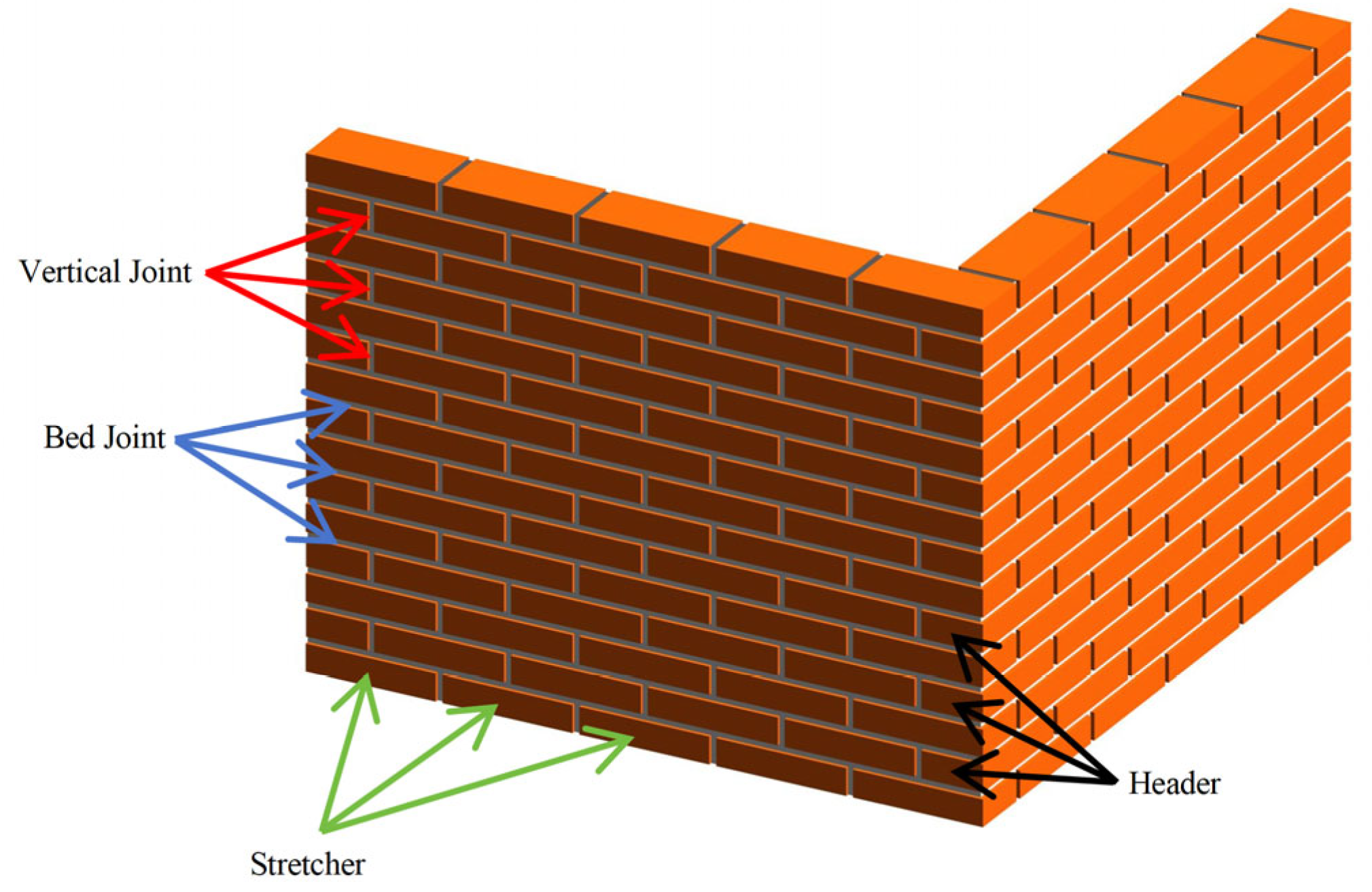
Figure 1. The bricks and mortar joints within the wall.
Buildings 15 03051 g001
Figure 2. Regional segmentation of L-shaped, T-shaped, and cross-shaped corners.
Buildings 15 03051 g002
Figure 3. Running Bond and English Bond layout rules.
Buildings 15 03051 g003
Figure 4. Systematic framework for layout optimization of masonry structures.
Buildings 15 03051 g004
Figure 5. Information of BIM model from Revit API.
Buildings 15 03051 g005
Figure 6. The layered layout of rectangular items.
Buildings 15 03051 g006
Figure 7. Two-dimensional layout model of masonry subrange layout optimization.
Buildings 15 03051 g007
Figure 8. Flowchart of brick layout optimization based on the SNS algorithm.
Buildings 15 03051 g008
Figure 9. Original BIM model of Instance (ac).
Buildings 15 03051 g009
Figure 10. Visual masonry unit layout results for Instance (ac).
Buildings 15 03051 g010
Figure 11. Dimension and subrange split of Instance (a,b).
Buildings 15 03051 g011
Figure 12. Visual masonry unit layout results for Instance (a,b).
Buildings 15 03051 g012
Figure 13. Two-dimensional design drawing of Case 3.
Buildings 15 03051 g013
Figure 14. Original BIM model of Case 3.
Buildings 15 03051 g014
Figure 15. The layout results of the two bond patterns in Case 3 are shown in (a,b).
Buildings 15 03051 g015
Table 1. Requirements for laying masonry walls in China, the United States, and Europe.
Layout RequirementsChinaUSEU
Grout thickness8–12 mm6.4–9.5 mm6–15 mm
Lapping rate1/31/42/5
Priority of block sizesWhole brick priority, with the variety of cut block sizes being minimized
Boundary constraintsThe length and height of the masonry wall after laying should be consistent with the design requirements
Table 2. Judgment matrix C1.
Odd-Course Bond PatternEven-Course Bond PatternLongitudinal Bond PatternCourse CountMortar Joint Thickness
Odd-Course Bond Pattern11375
Even-Course Bond Pattern11375
Longitudinal Bond Pattern 1 3 1 3 153
Course Count 1 7 1 7 1 5 1 1 3
Mortar Joint Thickness 1 5 1 5 1 3 31
Table 3. A comparison of the SNS algorithm and traditional metaheuristic algorithms.
Comparison DimensionTraditional Metaheuristic AlgorithmsSNS Algorithm
Inspiration sourceNatural phenomena (biological evolution, bird flocks)Human social behavior
Operator designSingle dominant mechanism (e.g., crossover, velocity update)Four-emotion collaborative mechanism with dynamic switching strategy
Exploration-exploitation balanceReliance on fixed parameters (e.g., inertia weight)Adaptive emotion selection without manual parameter tuning
Problem adaptabilityRequire problem-specific operator tuningNaturally suited for high-dimensional, multimodal, dynamic optimization problems
ObjectiveRapidly obtain locally feasible solutionsGlobally approximate optimal solution
Search strategyLocal search lacking randomnessGlobal exploration + local exploitation
GeneralityDependence on problem characteristicsStrong generalization capability
Table 4. Information about the wall in Case 1.
WallsCorner TypeLength (mm)Height (mm)
Wall 1a20002000
Wall 2a23002000
Wall 3b26002500
Wall 4b29002500
Wall 5b32002500
Wall 6c35003000
Wall 7c38003000
Wall 8c41003000
Wall 9c44003000
Table 5. Time spent on manual and program modeling.
InstanceBond TypeCorner TypeSubregion QuantityProgram Modeling Time (s)Manual Modeling Time (s)
aRunning BondL-shaped215.4223
English Bond15.5285
bRunning BondT-shaped319.5377
English Bond20.3553
cRunning BondCross-shaped425.2512
English Bond27.5871
Disclaimer/Publisher’s Note: The statements, opinions and data contained in all publications are solely those of the individual author(s) and contributor(s) and not of MDPI and/or the editor(s). MDPI and/or the editor(s) disclaim responsibility for any injury to people or property resulting from any ideas, methods, instructions or products referred to in the content.