Article

Design and Numerical Analysis of a Combined Pile–Raft Foundation for a High-Rise in a Sensitive Urban Environment

1
Frankfurt University of Applied Sciences, Nibelungenplatz 1, 60318 Frankfurt am Main, Germany
2
Vilnius Gediminas Technical University, Saulėtiekio Av. 11, 10223 Vilnius, Lithuania
*
Author to whom correspondence should be addressed.
Buildings 2025, 15(16), 2933; https://doi.org/10.3390/buildings15162933
Submission received: 28 July 2025 / Revised: 14 August 2025 / Accepted: 15 August 2025 / Published: 19 August 2025
(This article belongs to the Section Construction Management, and Computers & Digitization)

Abstract

Designing deep foundations in densely urbanized areas presents significant challenges due to complex soil conditions, high groundwater levels, and the proximity of sensitive infrastructure. This study addresses these challenges through the development and numerical analysis of a combined pile–raft foundation (CPRF) system for a 75 m tall hotel tower in Frankfurt am Main, Germany. The construction site is characterized by heterogeneous soil layers and is located adjacent to a historic quay wall and bridge abutments, necessitating strict deformation control and robust structural performance. A comprehensive three-dimensional finite element model was developed using PLAXIS 3D to simulate staged construction and soil–structure interaction (SSI). The CPRF system comprises a 2 m thick triangular raft and 34 large-diameter bored piles (1.5 m in diameter, 40–45 m in length), designed to achieve a load-sharing ratio of 0.89. The raft contributes significantly to the overall bearing capacity, reducing bending moments and settlement. The predicted settlement of the high-rise structure remains within 45 mm, while displacement of adjacent heritage structures does not exceed critical thresholds (≤30 mm), ensuring compliance with serviceability criteria. The study provides validated stiffness parameters for superstructure design and demonstrates the effectiveness of CPRF systems in mitigating geotechnical risks in historically sensitive urban environments. By integrating advanced numerical modeling with staged construction simulation and heritage preservation criteria, the research contributes to the evolving practice of performance-based foundation design. The findings support the broader applicability of CPRFs in infrastructure-dense settings and offer a methodological framework for future projects involving complex SSI and cultural heritage constraints.

1. Introduction

Foundation systems are critical structural components that ensure the safe transfer of loads to the ground, maintaining stability and serviceability under varying geotechnical conditions. The design of deep foundations for high-rise buildings in urban areas is a vital and evolving field in geotechnical engineering [1,2,3]. Urban construction sites often feature complex geological conditions, high groundwater levels, and nearby sensitive infrastructure [4]. These challenges require foundation systems that not only guarantee structural safety and serviceability but also minimize environmental and structural impacts during and after construction. In regions such as Frankfurt am Main, where seismic activity is negligible, the selection and design of deep foundations are governed primarily by the deformation behavior of over-consolidated clay layers. Frankfurt Clay (Frankfurter Ton) exhibits complex mechanical characteristics, including high stiffness gradients, layered heterogeneity, and deformation induced by unloading. Previous studies [5,6,7,8,9,10,11,12] have demonstrated that accurate modeling of these properties is essential for the reliable prediction of settlement and load-sharing behavior in CPRF systems. In particular, Franke et al. [5] performed numerical modeling and field measurements for high-rise foundations on Frankfurt Clay, demonstrating the importance of calibrating soil stiffness. Katzenbach and Leppla [6,7] analyzed the deformation behavior of clay due to unloading and its implications for urban construction. Abdel-Azim et al. [8] conducted a numerical investigation of piled raft foundations for the Messeturm building, confirming the optimized performance of combined pile–raft foundation (CPRF) systems in Frankfurt’s subsoil. In this context, CPRF systems have become a highly effective and flexible solution.
CPRF systems combine the load-bearing capabilities of piles and rafts, enabling a more balanced and efficient distribution of structural loads. This hybrid method has been proven to reduce total and differential settlement, optimize material usage, and enhance overall foundation performance [9,11,12,13,14]. The concept, first introduced by Davis and Poulos [9], has evolved through extensive theoretical, experimental, and numerical research. In addition to technical benefits, CPRF systems contribute to sustainability goals by reducing the volume of concrete and reinforcement required for deep foundations, thereby lowering CO2 emissions associated with construction activities [15,16]. Recent studies [13,14,15,16,17,18] emphasize the significance of soil–structure interaction (SSI), staged construction effects, and the nonlinear behavior of soils in CPRF performance. Still, studies [5,6,7,8] confirmed that the mechanical response of Frankfurt Clay—characterized by high pre-consolidation pressure, layered stiffness, and time-dependent deformation—requires advanced modeling approaches and significantly influences the design of deep foundations, even in non-seismic contexts.
Advanced finite element modeling (FEM) tools, such as PLAXIS and ABAQUS, have become crucial in CPRF design, enabling engineers to simulate complex SSI phenomena and assess the impact of different design parameters on outcomes [16,17,18,19,20,21,22]. For example, Mahata and Bera [16] demonstrated that raft thickness, pile length-to-diameter ratio, and pile spacing significantly influence the load-sharing behavior and settlement characteristics of CPRFs in granular soils. Similarly, Kumar and Kumar [18] used PLAXIS 3D to analyze settlement-based load-bearing behavior, highlighting the importance of accurate subsoil modeling. Deb and Pal [22] provided a systematic review of CPRF design principles and the numerical tools employed in this context.
Recent innovations in CPRF design [11,14,22,23] include the use of flexible rafts, optimization of pile configurations, and the integration of digital twin technologies for real-time monitoring. These developments have broadened the applicability of CPRFs beyond high-rise buildings to include bridges, offshore platforms, wind turbines, and nuclear facilities [1,18,20]. Furthermore, experimental investigations have validated numerical predictions, reinforcing the reliability of FEM-based design approaches [22].
In addition to technical challenges, constructing tall structures near historic sites increases complexity. Heritage buildings often lack modern foundations and are therefore more vulnerable to damage from ground movement. Studies [2,24] demonstrate that even minor ground shifts can compromise the integrity of such structures. Consequently, foundation design in these areas requires strict deformation limits and the use of predictive models to ensure the safety of nearby buildings, engineering structures, and utilities. Recent research [25,26,27] underscores the importance of geotechnical monitoring, risk assessment, and stakeholder collaboration when working near heritage sites.
This study contributes to the expanding field of CPRF research by providing a detailed design and numerical analysis of a CPRF system for a 75 m high hotel tower in Frankfurt am Main, Germany. The site features heterogeneous soil layers, high groundwater levels, and proximity to a historic quay wall and bridge abutments. These conditions demand a foundation solution that ensures both structural integrity and minimal impact on nearby infrastructure. The CPRF system, comprising a 2 m thick raft and 34 large-diameter bored piles, was selected for its proven ability to distribute loads and control settlement effectively. The design adheres to Eurocode 7 [28] and the CPRF guideline [29], ensuring compliance with Geotechnical Category 3—the highest complexity classification—which addresses significant geotechnical risks, such as sensitive urban environments, high-rise buildings, and heritage preservation. A comprehensive three-dimensional finite element model was developed using PLAXIS 3D to simulate staged construction, SSI, and the influence of the foundation system on nearby structures. This model incorporates advanced soil behavior laws to deliver accurate predictions of settlement, displacement, and load-sharing performance.
The manuscript begins with a general overview of CPRF systems, including their design principles and load–deformation behavior, to provide context for the complexity of the foundation problem. This overview is followed by a detailed description of the site conditions and foundation concept, the development of the numerical model, and the simulation of construction phases. The Results Section presents the predicted settlement and displacement, along with their impact on the serviceability of nearby historic structures. Finally, the study provides validated stiffness parameters for superstructure design and confirms the effectiveness of the CPRF in mitigating risks associated with foundation construction in sensitive urban environments. Building on this context, the present study demonstrates how the CPRF system can be adapted to environments with dense infrastructure and strict deformation limits. The framework combines staged construction simulation, heritage-sensitive design criteria, and stiffness parameter extraction to model the superstructure. Unlike traditional CPRF investigations, which often focus on isolated structural systems, this work examines the interaction between multiple structures in a culturally sensitive urban setting.

2. Materials and Methods

This study focuses on the design and numerical analysis of a CPRF system for a 75 m tall hotel tower in Frankfurt am Main, Germany, as shown in Figure 1a (building visualization). Figure 1b depicts the current construction site.
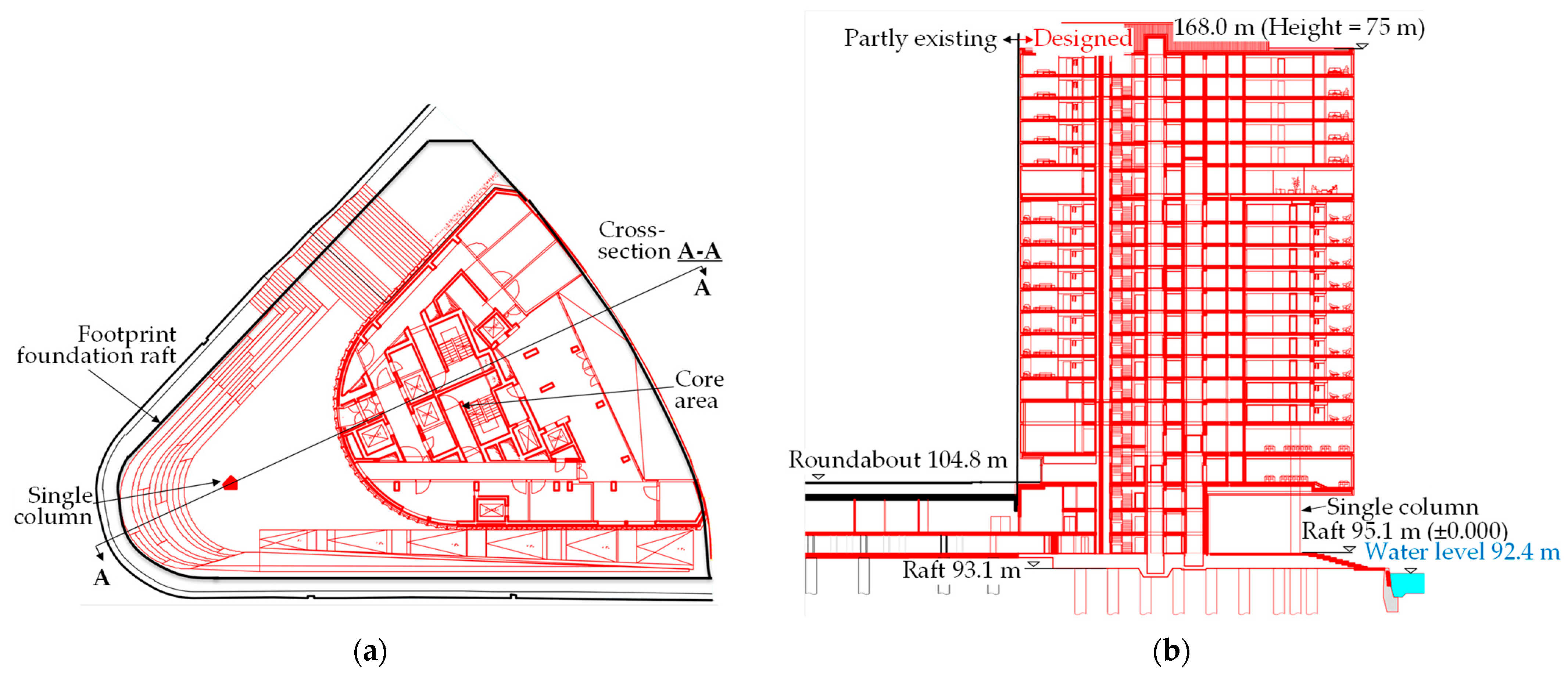
The site lies between the Main River and the eastern harbor (Figure 1b) in a densely developed area with sensitive infrastructure, including a historic quay wall and bridge abutments. The high-rise has 21 floors and stands 75 m tall. All floors are situated above the water level of the Main River, removing the need for excavation. Figure 2 provides a plan view and a cross section. The superstructure is made of reinforced concrete, with vertical loads carried by walls and columns to the foundation raft. The elevator and stairway shafts maintain the horizontal stability of the high-rise.

2.1. Design Principles and Load–Deformation Behavior

Combined pile–raft foundations (CPRFs) integrate the load-bearing capacities of a foundation raft and deep foundation elements such as piles or barrettes. These hybrid systems are classified under Geotechnical Category 3 (GC3) according to Eurocode 7 [28], reflecting their complexity and the need for advanced design and verification procedures.
The design of CPRFs aims to ensure a balanced distribution of structural loads between the raft and the piles. Piles should be placed directly beneath major structural elements, with the centroid of the pile group aligned with the center of applied loads. Fewer long piles are generally more effective than many short ones, and pile lengths should be adjusted based on load intensity—shorter piles near raft edges and longer ones in central zones. The outlined principles for pile placement and length adjustment enhance structural performance and material efficiency. In addition to these benefits, they govern the load–deformation behavior of CPRFs, which results from the interaction between the raft, piles, and subsoil. Field measurements from high-rise buildings in Frankfurt am Main, Germany, indicate that between 60% and 80% of the settlement is localized within the upper third of the influenced soil volume. In CPRFs, a portion of the load is transferred through the piles to deeper, stiffer soil layers, while the raft continues to make a significant contribution to the bearing capacity.
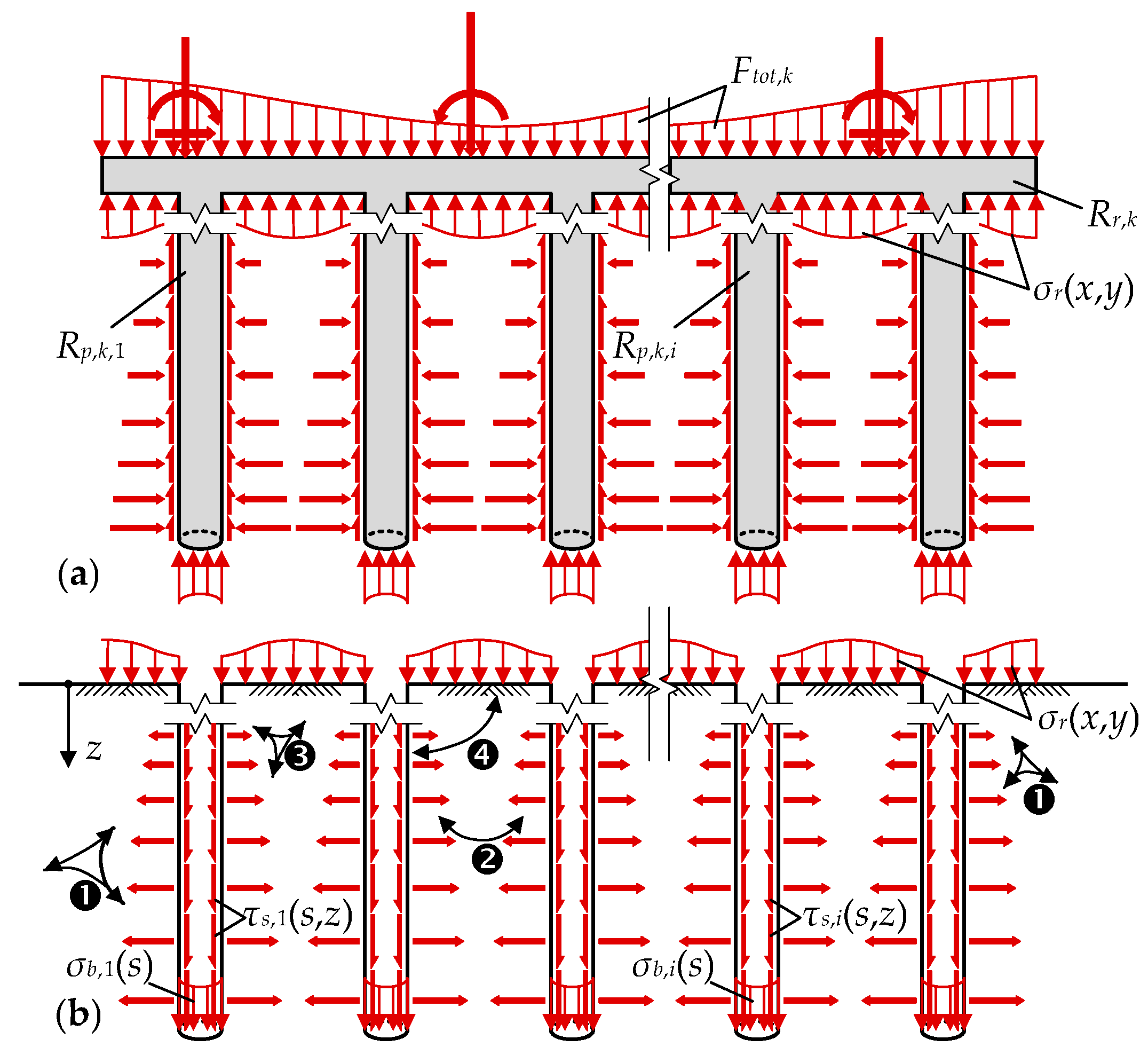
Figure 3 illustrates the load-sharing mechanism between the raft, piles, and subsoil in a schematic manner. Figure 3a shows the CPRF resistance components. In Figure 3b, the numbered labels indicate the interaction mechanisms: ❶ means the pile–soil interaction; ❷ defines the pile–pile interaction; ❸ determines the raft–soil interaction; ❹ presents the pile–raft interaction. Following guideline [30], the total resistance of a CPRF system, Rtot,k(s), is the sum of the raft resistance Rr,k(s) and the resistance of all piles ∑Rp,k(s):
R t o t , k s = R r , k s + i R p , k , i s .
This equation considers the functional dependence of the resistance on settlement s; index i refers to the individual piles within the foundation system, as shown in Figure 3. Integration of the soil contact pressure σr(x,y) beneath the foundation raft (Figure 3) determines resistance Rr,k(s). Assuming a cylinder shape of piles, each pile’s resistance comprises skin friction, Rs,k,i(s), and base resistance, Rb,k,i(s):
R p , k , i s = R b , k , i s + R s , k , i s = σ b , i s · π · D 2 4 + τ s , i s , z · π · D · d z ,
where σb,i and τs,i(s,z) are the pile base stress and skin friction stress.
CPRF load-sharing ratio α quantifies the proportion of the load carried by the piles:
α = i R p , k , i s R t o t , k s .
An optimal design targets α values between 0.5 and 0.7, striking a balance between technical performance and economic efficiency. Numerical methods, typically FEM, are well-suited to simulating CPRF behavior. Calibration of FEM models is commonly based on back analysis of pile load tests [16,19,22].

2.2. Design and Safety Concept

The design of CPRFs must satisfy both ultimate limit state (ULS) and serviceability limit state (SLS) requirements [28]. For ULS analysis, the design load Ftot,d is calculated using a safety factor γ = 2.0:
F t o t , d = 2.0 · G t o t , k + Q t o t , k ,
where Gtot,k and Qtot,k are the characteristic permanent and traffic loads.
For SLS analysis, the expected characteristic load includes one-third of the traffic load and potential uplift due to groundwater:
F t o t , k = G t o t , k + 1 3 · Q t o t , k + A k ,
where Ak is a possible characteristic uplift.
To evaluate stiffness parameters, the full characteristic load is used:
F t o t , k = G t o t , k + Q t o t , k .
The theoretical framework presented in this section provides the basis for interpreting the numerical results and evaluating the performance of the CPRF system under complex geotechnical and structural conditions. The following sections apply these principles to a real-world case study, demonstrating how advanced modeling techniques can be used to optimize CPRF design in a sensitive urban environment.

2.3. Description of the Project

The subsoil profile, determined through core drilling and extensive laboratory testing, revealed a stratigraphy comprising artificial fill (0.7–16 m), quaternary alluvial clay and sand/gravel (0.6–3.1 m), and tertiary marl extending beyond 80 m. These findings align with typical urban soil profiles in central Europe, as discussed by Norkus et al. [3], Mandolini et al. [31], and Viggiani et al. [32], and require a foundation system capable of supporting heterogeneous and compressible layers. The heterogeneous soil layers, high groundwater levels, and proximity to the existing bridge abutments demanded a complex design foundation scheme for a high-rise, with an admissible direct impact on the roundabout intersection (constructed under the road level for entrance into two-level parking) and impact on a 100-year-old historic quay wall, at the boundary of the construction site. The historic quay wall is constructed from plain concrete, and the southern bridge abutment is a massive concrete block. The roundabout intersection is resting on the usual piled foundations. Both abutments are integrated into the structural system of the roundabout intersection (Figure 1b). Thus, the new foundation system and neighboring structures must ensure both structural integrity and minimal impact on nearby infrastructure.
The CPRF system consists of a 2 m thick triangular raft (815 m2) and 34 bored piles with diameters of 1.5 m and lengths ranging from 40 m to 45 m. The total characteristic load on the foundation is approximately 507 MN, with significant eccentricity due to the building geometry. Table 1 outlines the primary design conditions and limitations, which serve as reference criteria throughout the numerical analysis, while Table 2 specifies the loading conditions chosen to simulate realistic deformation values. On this basis, the following load combination, which combines the characteristic value of the permanent load, Gtot,k, and 1/3 of the distinctive value of the traffic (variable) load, Qtot,k, was chosen as the design load combination. The assumed configuration aligns with recommendations by Randolph [33] and Katzenbach et al. [34], who emphasize the efficiency of CPRFs in reducing differential settlement and optimizing material use in high-rise construction. These values are also consistent with the performance criteria established in previous CPRF studies [9,11,19].
To assess the performance of the CPRF and its interaction with surrounding structures, a detailed FEM was created using PLAXIS 3D (Version 2, PLAXIS HEADQUARTERS, Delft, The Netherlands). The model area spans 200 × 200 m in a plan view and 105 m in depth. The simulation incorporated staged construction, mirroring the actual site development sequence—from initial ground conditions to the activation of superstructure loads. Soil behavior was modeled using two constitutive laws: the Mohr–Coulomb (MC) model for artificial fill and the hardening soil (HS) model for natural layers. The HS model, as recommended by Deb and Pal [22], captures stress-dependent stiffness and irreversible strains, providing a more realistic representation of subsoil behavior under high-rise loading. The mechanical parameters were calibrated based on laboratory tests and are consistent with values reported in similar studies [14,16].
Structural elements, including the raft, piles, and retaining walls, were modeled as linear elastic materials. Concrete was assigned a modulus of elasticity of 30 GPa and a Poisson’s ratio of 0.2; steel elements were modeled with a modulus of elasticity of 210 GPa and a Poisson’s ratio of 0.3. These values are typical in CPRF modeling and align with those used in recent numerical investigations by Mahata and Bera [16] and Kumar and Kumar [18]. The target CPRF load-sharing ratio (α) is 0.89, which indicates that the piles support 89% of the total load. This condition aligns with findings by Horikoshi and Randolph [35], who reported similar ratios for CPRFs in layered soils. The raft significantly contributes to the overall bearing capacity, helping to reduce bending moments and settlement. The spring stiffness of the piles and the subgrade reaction modulus of the raft were calculated from the FEM and used in the superstructure design, following the method outlined by Poulos et al. [36]. By combining advanced numerical modeling with staged construction simulations and validated soil parameters, this study shows the feasibility and reliability of CPRF systems in complex urban settings. The approach adheres to international best practice [2,37,38,39] and contributes to the growing body of evidence supporting the use of CPRF in geotechnically challenging environments.

3. Numerical Modeling

Building on the foundation concept and site conditions described in Section 2, a detailed 3D FEM was created to simulate the behavior of the CPRF system and its interaction with the surrounding built environment. This finite element modeling approach aimed to capture the complex SSI process, staged construction effects, and the impact of heterogeneous subsoil conditions.

3.1. Numerical Model Setup and Material Properties

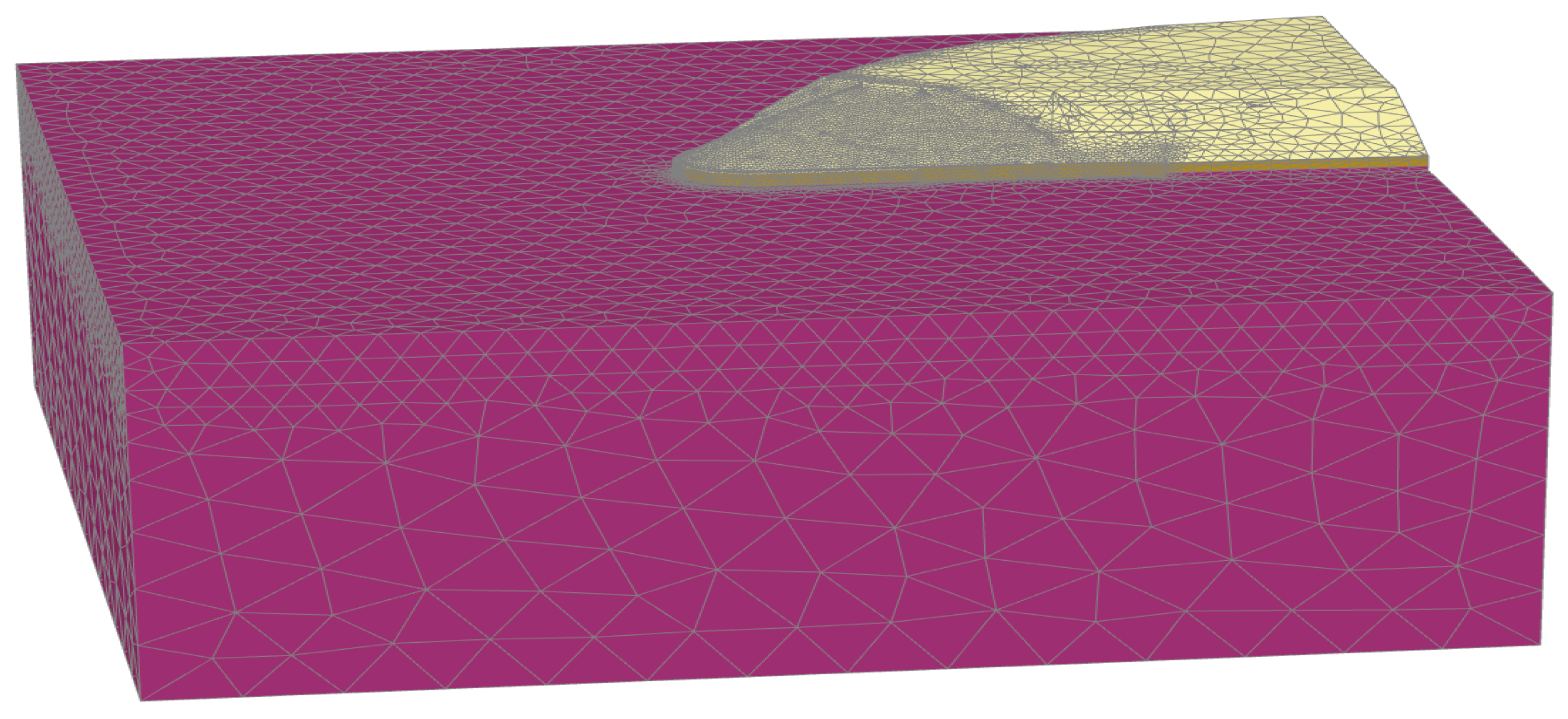
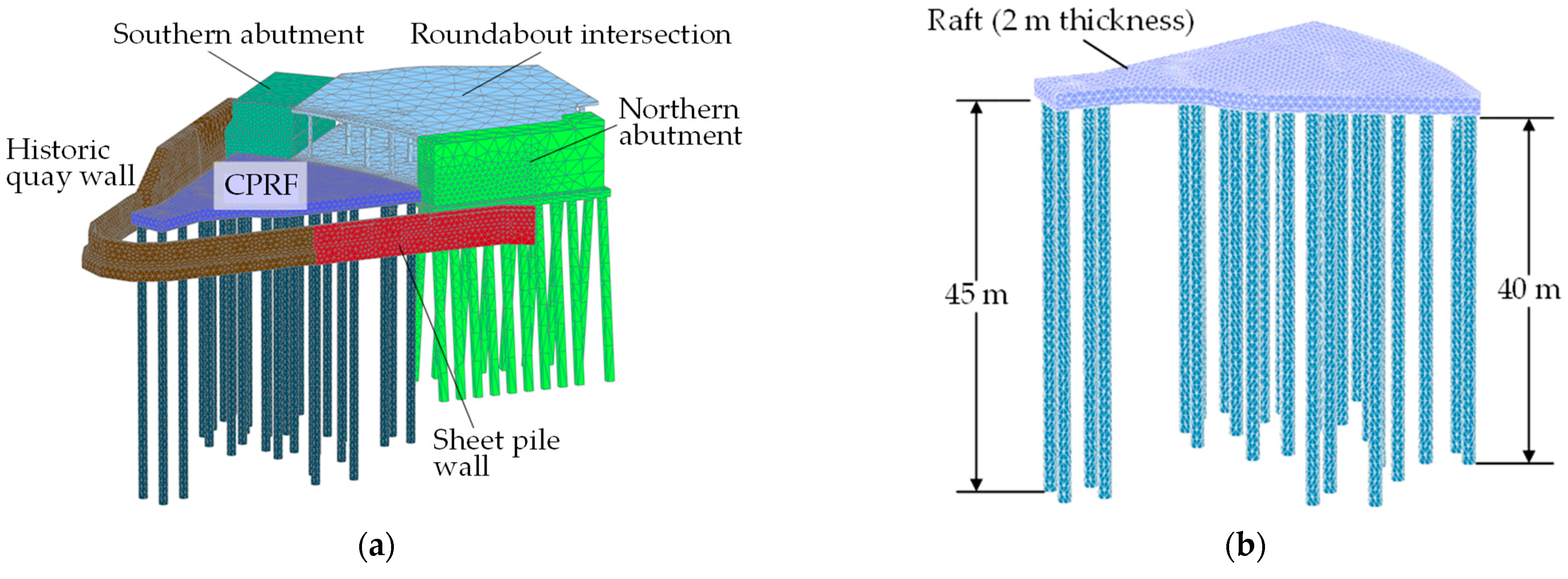
The FEM was built using PLAXIS 3D (Version 2, PLAXIS HEADQUARTERS, Delft, The Netherlands), covering a 200 m by 200 m area in plan and extending to a depth of 105 m. Figure 4 illustrates the finite element model domain, which encompasses the Main River and its surrounding subsoil layers, comprising over 770 × 103 finite elements and 1.2 million nodes. Figure 5a illustrates the detailed model. As described in Section 2.3, the CPRF system, which includes a 2 m thick triangular raft and 34 bored piles (1.5 m diameter, 40–45 m long), was modeled in detail (Figure 5b).
The subsoil stratigraphy, as determined from core drilling and laboratory testing, was represented using two constitutive models:
  • Mohr–Coulomb (MC) for the artificial fill;
  • Hardening soil (HS) for natural layers, including quaternary alluvial deposits and tertiary marl.
The MC model was applied to the artificial fill due to its limited thickness and inhomogeneity. The HS model was used for natural layers, with parameters calibrated through back analysis of local foundation projects [5,6,7,8]. The HS model was selected for its ability to simulate stress-dependent stiffness and irreversible strains, which are critical for capturing the nonlinear behavior of soils under high-rise loading [16,22]. To realistically simulate the contact between the piles and the surrounding subsoil, interface elements were implemented around each pile. These interfaces consist of node pairs—one associated with the pile and the other with the soil—linked by elastic–perfectly plastic springs that permit slip displacement and accurately represent pile–soil interaction.
Table 3 summarizes the mechanical parameters used in the simulations. In this table, γsat is the unit weight of saturated soil, γunsat is the unit weight of unsaturated soil, φ’ is the effective angle of internal friction, c’ is the effective cohesion, Ψ is the dilatancy angle, E is Young’s modulus, E50,ref is the secant stiffness in the standard drained triaxial test, Eoed,ref is the tangent stiffness for primary oedometer loading, Eur,ref is the unloading/reloading stiffness, ν is Poisson’s ratio, νur is Poisson’s ratio for unloading–reloading, K0 is the coefficient of initial lateral pressure, and Rf is the failure ratio. All these parameters were determined during the laboratory tests of the local soil samples. To ensure reliable simulation results, the mechanical parameters used in the numerical model were calibrated through back analysis of several foundation projects in Frankfurt am Main, as documented by Franke et al. [5], Katzenbach and Leppla [7], and Abdel-Azim et al. [8], ensuring consistency with local soil behavior and validated geotechnical practice.
Structural elements, such as the raft, piles, and retaining walls, were modeled as linear elastic materials as described in Section 2.3. The assumed values align with those used in recent CPRF studies [16,18,34].

3.2. Simulation Strategy and Parameter Extraction

The construction process was modeled in stages, mirroring the actual order of site development. This included installing the quay wall, bridge abutments, micro piles, and CPRF system, followed by the application of superstructure loads. Such staged modeling is essential for accurately capturing time-dependent deformations and load redistribution, as demonstrated in previous numerical studies [18,21,22].
The construction sequence included the excavation of fill material, the installation of dewatering wells to control groundwater levels, and the staged activation of structural elements. Dewatering was initiated before raft excavation and maintained throughout pile installation and raft concreting. The numerical simulation was structured to reflect the actual sequence of construction activities, ensuring realistic stress redistribution and time-dependent deformation. The initial phase established geostatic stress equilibrium by activating gravity and resetting displacement to zero. This stage was followed by the simulation of historical developments, including the installation of quay walls, the construction of the southern bridge abutment, and the roundabout intersection with its foundation piles and superstructure. Subsequently, the northern bridge abutment was modeled with corresponding load applications.
For the planned building, the simulation included the excavation of fill material, the installation of foundation piles, the concreting of the CPRF raft, the activation of raft stiffness with displacement reset, and the stepwise application of loads corresponding to stiffness evaluation, SLS, and ULS conditions, as defined in Section 2.2. The groundwater table was assumed constant throughout all phases, as the bottom of the foundation raft remains above the river water level at all times, eliminating the need for dewatering or groundwater lowering. This sequence was implemented in the FEM to capture realistic stress redistribution and time-dependent deformation. To support the structural design of the superstructure, the FE model was used to extract the following:
  • Pile spring stiffness extracted from the load–settlement response at pile heads;
  • Subgrade reaction modulus, derived from the stress–settlement behavior beneath the raft.
These parameters were used in the structural model of the high-rise, ensuring compatibility between geotechnical and structural design domains (Figure 5). The approach follows the methodology outlined by Poulos et al. [36], which has been extensively applied in geotechnical modeling and is further supported by recent applications in high-rise foundation design [14,19].

4. Results and Discussion

4.1. Load Sharing and Foundation Performance

The CPRF system achieved a load-sharing ratio (α) of 0.89, indicating that the piles carry 89% of the total load (507 MN). Simultaneously, the raft plays a significant role in increasing the overall bearing capacity. This ratio aligns with findings by Horikoshi and Randolph [35] and Mahata and Bera [16], confirming the consistency of the present results with previously reported values for CPRFs in layered soils.
A high α-value confirms the effectiveness of the CPRF structure in managing eccentric loads and reducing bending moments in the raft, as also emphasized in [9,10,14]. The results also align with the optimization strategies discussed in [11,21], which show that pile configuration and raft flexibility influence load distribution.

4.2. Settlement Predictions and Structural Implications

Serviceability requirements for the superstructure (high-rise) in terms of point settlement, differential settlement, and angular displacement govern the limit states set (ultimate and serviceability limits) due to their rigorous limiting values. Figure 6 shows the predicted distribution of settlement for the CPRF foundation. The determined settlement, corresponding to the full characteristic loads (as defined in Section 2.2 and Eurocode 7 [28]), varies between 32 mm and 55 mm (Figure 6a). It is essential to note that the 55 mm settlement shown in Figure 6a reflects design-stage modeling assumptions, specifically the analysis of the subgrade reaction modulus of the raft and the spring stiffness of the piles, which are needed for the superstructure design. These modeling conditions do not represent the expected service conditions. The SLS analysis, illustrated in Figure 6b, yields settlement ranging from 25 mm to 45 mm, which remains within the allowable limit defined in Table 1.
However, considering a reliable combination of the full characteristic dead load, Gtot,k, and 1/3 of the characteristic traffic load, Qtot,k, it ranges from 25 mm to 45 mm (Figure 6b), remaining within the allowable limit of 45 mm (Table 1). Settlement at the roundabout intersection and the bridge abutments is estimated to range from 5 mm to 25 mm.
The key deformation parameters of the foundation system, which includes the superstructure, roundabout intersection, and bridge abutments, must be verified against the design limits (ultimate and serviceability requirements). Analyzing settlement distribution reveals the most critical cases that require verification—those approaching critical thresholds (Table 1) and those within acceptable utilization levels.
The key values governing the foundation system are differential settlement and angular displacement. The settlement distribution shown in Figure 6b indicates a variation of 5 mm to 20 mm. The maximum differential settlement between the building and the roundabout intersection reaches 15 mm at point A (Figure 6b). The calculated maximum angular displacement, ψ, does not exceed 1/952 and is considered non-critical. Thus, both the maximum differential settlement and angular rotation are assumed to be manageable and rational when the connecting structures are detailed appropriately. All calculated deformation parameters, including point settlement, differential settlement, and angular rotation, remain within the allowable limits defined in Table 1, confirming that the CPRF system satisfies the serviceability requirements for both the high-rise and adjacent structures.
These results align with experimental and numerical findings in [13,18,19], which demonstrate that CPRFs can effectively control settlement, even in heterogeneous soils. The findings also support the conclusions of Deb and Pal [22], who emphasized the importance of accurate soil modeling in predicting settlement behavior.

4.3. Impact on the Historic Quay Wall

New loads influence the historic quay wall due to the combined loading of the structural system, which includes a high-rise building, a roundabout intersection, and northern and southern bridge abutments. Since the quay wall is located far from the high-rise, the main load is lateral pressure on the wall. Therefore, both ultimate and serviceability states must be assessed. Additional vertical loading on the quay wall is minimal; the primary effect is the distribution of lateral displacement of the wall.
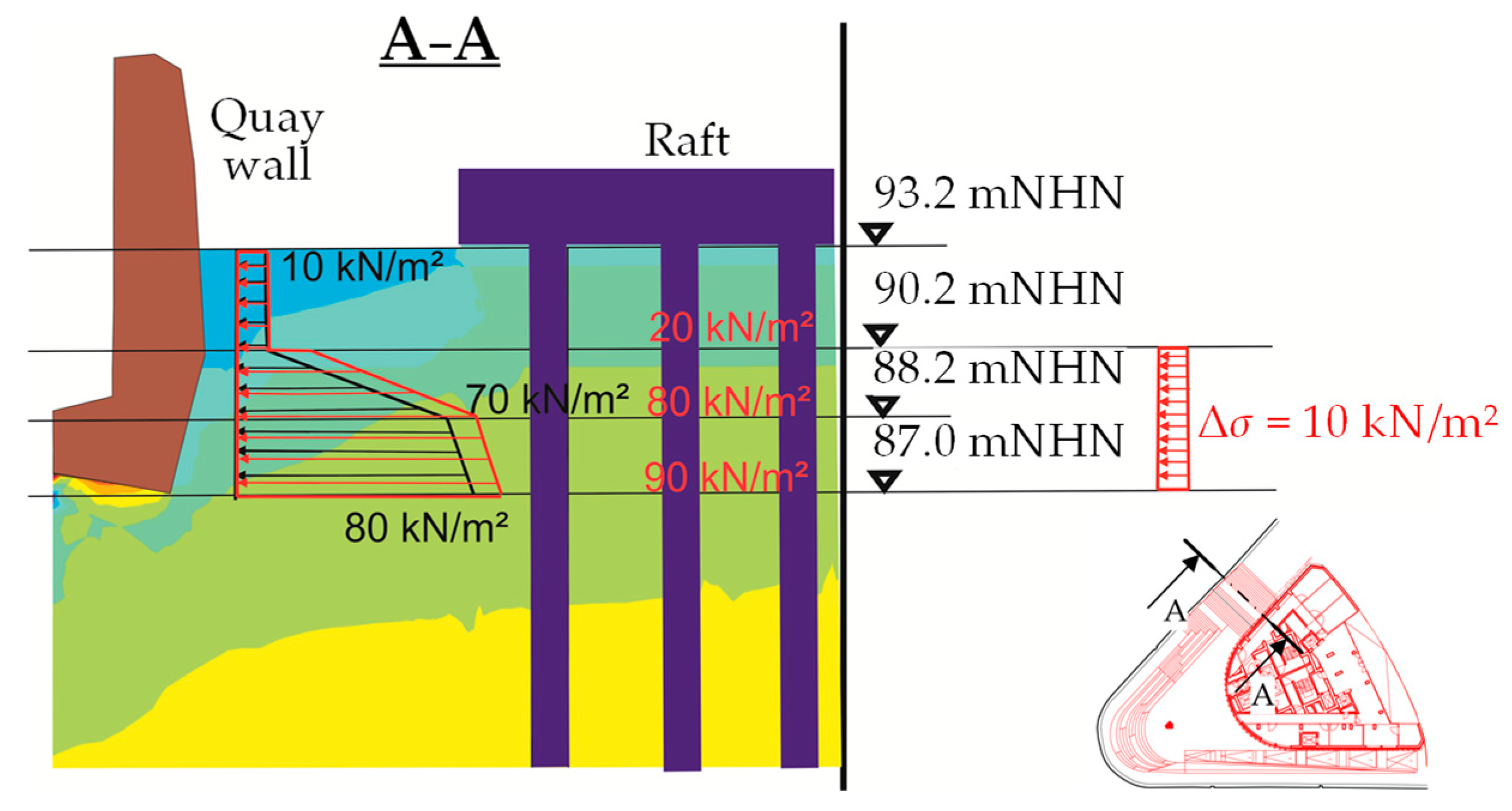
The most informative results from the simulation include the lateral displacement distribution of the quay wall (Figure 7), which examines serviceability requirements, and the lateral pressure (Figure 8), which assesses potential cracking and buckling due to incremental lateral pressure and vertical loads from the designed structural system. Numerical simulation results for the most critical load combinations are as follows:
  • The historic quay wall exhibits horizontal displacement of ≤5 mm (Figure 7b) and vertical settlement of 10–30 mm, with a maximum angular rotation ∆s/L (ratio of differential settlement ∆s by distance L of the neighboring settlement), ψ, of 1/1000, which is below the critical threshold of 1/500 [2].
  • The additional lateral stresses on the quay wall, induced by the building loads in cross-section A−A shown in Figure 8. The extra stresses begin at a depth of 3 m below the raft and are approximately 10 kN/m2. Although they are not significant, the impact of these additional stresses on the stability of the quay wall must be considered.
These findings confirm that the CPRF design ensures the safety of nearby heritage structures, consistent with the recommendations in [24,25,26,27] regarding deformation limits near sensitive infrastructure. The results also validate the use of angular rotation as a serviceability criterion, as discussed in [29].

4.4. Broader Implications, Innovation, and Research Outlook

The findings of this study support the growing consensus in the literature that CPRFs are highly effective in addressing complex geotechnical and structural challenges in urban environments. However, this study makes significant advances in several key areas.
First, employing a fully staged construction simulation in a dense, infrastructure-rich environment marks a notable methodological advancement in simulating multi-structure interactions within dense urban environments. While staged modeling has been used in prior studies [16,18,22], its combination with multiple interacting structures—including a heritage quay wall, bridge abutments, and a roundabout intersection—has rarely been explored in such detail. This method enables more precise predictions of time-dependent deformation and load redistribution, which are crucial for ensuring serviceability and safety in urban projects [21,36].
Second, the study directly incorporates heritage preservation criteria into the geotechnical design process. Using angular rotation limits (e.g., ψ ≤ 1/500) to assess the impact on the historic quay wall aligns with recommendations in [2,29]. Yet, few CPRF studies explicitly incorporate and validate these criteria within numerical simulations. This integration demonstrates how geotechnical design can support the protection of cultural heritage, a growing concern in urban redevelopment [24,25,26,27].
Third, extracting stiffness parameters (pile spring stiffness and subgrade reaction modulus) from the FEM for use in structural design fills an essential gap between geotechnical and structural engineering. This approach, although discussed in foundational works like Poulos et al. [36], is often overlooked in practical applications. By providing validated stiffness values, the study improves the accuracy of superstructure modeling and supports performance-based design.
These contributions position the study at the crossroads of advanced numerical modeling, urban geotechnics, and heritage-sensitive design. From a cost-efficiency perspective, the CPRF system offers substantial advantages over conventional pile foundations. These savings are directly attributable to the reduced pile lengths enabled by the CPRF design. In the considered case, numerical simulations indicate that a classic pile foundation would require pile lengths exceeding 60 m, significantly increasing construction costs. In contrast, the CPRF system achieves comparable performance with pile lengths of 40–45 m. Given the exponential increase in costs associated with deeper drilling, the CPRF solution is estimated to reduce pile production costs by approximately 70% while maintaining compliance with serviceability and structural requirements. The results not only confirm the feasibility of CPRF systems in challenging environments but also demonstrate their adaptability and resilience. Looking ahead, several research directions emerge:
  • Parametric studies could examine the effects of pile spacing, raft geometry, and soil variability on load-sharing behavior and settlement control, building on the work of Gunawan et al. [14] and Mahata and Bera [16].
  • Probabilistic modeling can address uncertainties in soil properties and construction sequences, improving the robustness of CPRF design under variable conditions [22].
  • Digital twin integration offers opportunities for real-time monitoring and adaptive design, particularly in heritage-sensitive areas, as highlighted by recent advances in geotechnical tracking [25,26].
  • Field validation through instrumentation and long-term monitoring will provide empirical evidence for numerical predictions and improve the modeling approach.
By addressing these areas, future research can expand the versatility and reliability of CPRF systems, supporting their broader adoption in sustainable and resilient urban development.

5. Concluding Remarks

This study presents the design and numerical analysis of a combined pile–raft foundation (CPRF) system for a 75 m tall hotel tower located in a historically sensitive and geotechnically complex area of Frankfurt am Main, Germany. The site, characterized by heterogeneous soil layers, high groundwater levels, and proximity to heritage structures, posed significant challenges for foundation design. Utilizing advanced 3D finite element modeling, the study effectively simulated staged construction, soil–structure interaction, and the impact of the CPRF system on nearby infrastructure.
The results showed that the CPRF system achieved a high load-sharing ratio (α = 0.89), with the raft playing a significant role in the overall bearing capacity. Predicted settlement of the high-rise remained within 45 mm, while displacement of nearby heritage structures, including the historic quay wall and bridge abutments, stayed below critical thresholds. The study also provided validated stiffness parameters for superstructure design, ensuring compatibility between geotechnical and structural models.
Innovative Contributions. In comparison to the existing literature, this study provides several new contributions:
  • It applies a fully staged construction simulation to a multi-structure urban context, capturing the sequential development of interacting elements.
  • It integrates heritage preservation criteria (e.g., angular rotation limits) into the numerical modeling framework, which is rarely addressed in CPRF studies.
  • It provides a stiffness extraction methodology for use in structural modeling, enhancing compatibility between geotechnical and structural design domains.
These innovations extend the use of CPRF beyond traditional high-rise settings, allowing it to be deployed in historically sensitive and infrastructure-dense environments.
Future Research Directions. While this study confirms the feasibility of CPRF systems in complex urban settings, several promising directions for future research remain:
  • Parametric studies to evaluate the influence of pile configuration, raft thickness, and soil variability on load-sharing behavior and settlement control.
  • Integration of digital twin technologies for real-time geotechnical monitoring and adaptive foundation design, particularly in heritage-sensitive zones.
  • Probabilistic modeling to quantify the impact of soil variability and construction uncertainties on CPRF performance.
  • Experimental validation through field instrumentation and long-term monitoring of the constructed foundation system.
By addressing these areas, future work can further enhance the robustness, sustainability, and adaptability of CPRF systems in challenging geotechnical environments.

Author Contributions

Conceptualization, S.L. and A.N.; methodology, S.L. and A.N.; software, S.L.; validation, S.L., A.N. and V.G.; formal analysis, S.L. and V.G.; investigation, S.L.; resources, S.L.; data curation, S.L.; writing—original draft preparation, S.L. and A.N.; writing—review and editing, V.G.; visualization, S.L., M.K. and V.G.; supervision, S.L.; project administration, M.K.; funding acquisition, S.L. All authors have read and agreed to the published version of the manuscript.

Funding

This research received no external funding.

Data Availability Statement

The original contributions presented in the study are included in the article; further inquiries can be directed to the corresponding author.

Conflicts of Interest

The authors declare that they have no conflicts of interest.

References

  1. Poulos, H.G. Foundation Design for Tall Buildings. In Proceedings of the Geotechnical Engineering State of the Art and Practice: Keynote Lectures from GeoCongress, Oakland, CA, USA, 25–29 March 2012; pp. 786–809. [Google Scholar] [CrossRef]
  2. Jiang, Z.; Zhu, S.; Que, X.; Ge, X. Deformation effects of deep foundation pit excavation on retaining structures and adjacent subway stations. Buildings 2024, 14, 2521. [Google Scholar] [CrossRef]
  3. Norkus, A.; Martinkus, V.; Mandolini, A.; Gribniak, V. Experimental study of ground resistance of short displacement piles and pile groups in artificial deposition of natural sand. Eur. J. Environ. Civ. Eng. 2025, 1–24. [Google Scholar] [CrossRef]
  4. Tian, J.; Xia, Y.; Zhang, J.; Liu, H.; Zhang, M.; Gao, Y.; Liu, J.; Han, B.; Huang, S. Urban underground space geological suitability—A theoretical framework, index system, and evaluation method. Appl. Sci. 2025, 15, 4326. [Google Scholar] [CrossRef]
  5. Franke, E.; Lutz, B.; El-Mossallamy, Y. Measurements and numerical modelling of high-rise building foundations on Frankfurt Clay. Vert. Horiz. Deform. Found. Embankments ASCE Geotech. Spec. Publ. 1994, 40, 1325–1336. [Google Scholar]
  6. Katzenbach, R.; Leppla, S.; Seip, M. Das Verformungsverhalten des Frankfurter Tons infolge Baugrundentlastung. Bauingenieur 2011, 86, 233–240. (In German) [Google Scholar]
  7. Katzenbach, R.; Leppla, S. Deformation behavior of clay due to unloading and the consequences on construction projects in inner cities. In Proceedings of the 18th Conference of the International Society for Soil Mechanics and Geotechnical Engineering, Paris, France, 2–6 September 2013; Volume 3, pp. 2023–2026. [Google Scholar]
  8. Abdel-Azim, O.A.; Abdel-Rahman, K.; El-Mossallamy, Y.M. Numerical investigation of optimized piled raft foundation for high-rise building in Germany. Innov. Infrastruct. Solut. 2020, 5, 11. [Google Scholar] [CrossRef]
  9. Davis, E.H.; Poulos, H.G. The analysis of piled raft systems. Aust. Geotech. J. 1972, 2, 21–27. [Google Scholar]
  10. Clancy, P.; Randolph, M.F. Simple design tools for piled raft foundations. Geotechnique 1996, 46, 313–328. [Google Scholar] [CrossRef]
  11. Bhaduri, A.; Choudhury, D. Steady-state response of flexible combined pile-raft foundation under dynamic loading. Soil Dyn. Earthq. Eng. 2021, 145, 106664. [Google Scholar] [CrossRef]
  12. Tarenia, K.; Patra, N.R. Long-term effect of vertical and lateral loads on piled raft foundations: A case study. Proc. Inst. Civ. Eng.-Geotech. Eng. 2024, 177, 337–349. [Google Scholar] [CrossRef]
  13. Pandey, G.; Mourya, V.K.; Patel, D.; Kumar, R.; Kumar, S. Load sharing behaviour in piled-raft foundations over sand and clay: An experimental investigation. Res. Eng. Struct. Mater. 2024, 10, 917–942. [Google Scholar] [CrossRef]
  14. Gunawan, H.; Flessati, L.; Marveggio, P. Optimizing foundation performance: The impact of raft on piled raft foundation in sand. Géotechnique Lett. 2025, 1–5. Available online: https://www.sciencedirect.com/org/science/article/abs/pii/S2045254325000239 (accessed on 13 August 2025).
  15. Akbari, A.; Eslami, A. Performance of composite piled raft foundations with long and short piles under static and seismic loading. Geotech. Geol. Eng. 2025, 43, 188. [Google Scholar] [CrossRef]
  16. Mahata, K.; Bera, A.K. Load settlement and load sharing characteristics of a combined pile-raft foundation in granular soil deposits: A numerical simulation approach. Transp. Infrastruct. Geotechnol. 2025, 12, 88. [Google Scholar] [CrossRef]
  17. Wang, J.; Xie, Y.; Guo, T.; Du, Z. Predicting the influence of soil–structure interaction on seismic responses of reinforced concrete frame buildings using convolutional neural network. Buildings 2023, 13, 564. [Google Scholar] [CrossRef]
  18. Kumar, A.; Kumar, S. Settlement based load-bearing in a combined pile–raft foundation. Geotech. Geol. Eng. 2024, 42, 1405–1421. [Google Scholar] [CrossRef]
  19. Chimdesa, F.F.; Chimdesa, F.F.; Jilo, N.Z.; Hulagabali, A.; Babalola, O.E.; Tiyasha, T.; Ramaswamy, K.; Kumar, A.; Bhagat, S.K. Numerical analysis of pile group, piled raft, and footing using finite element software PLAXIS 2D and GEO5. Sci. Rep. 2023, 13, 15875. [Google Scholar] [CrossRef]
  20. Islam, M.R.; Turja, S.D.; Van Nguyen, D.; Forcellini, D.; Kim, D. Seismic soil-structure interaction in nuclear power plants: An extensive review. Results Eng. 2024, 23, 102694. [Google Scholar] [CrossRef]
  21. Singh, G.G.; Tiwari, R.P.; Kumar, V. Insights into the behaviour of piled raft foundations under vertical-horizontal-moment loading conditions. Transp. Infrastruct. Geotechnol. 2025, 12, 60. [Google Scholar] [CrossRef]
  22. Deb, P.; Pal, S.K. Evolution of piled raft foundation at static loading condition and application of numerical modelling: A state-of-the-art review. Arch. Comput. Methods Eng. 2025, 32, 1097–1133. [Google Scholar] [CrossRef]
  23. Reul, O.; Randolph, M. Combined Pile-Raft Foundations: Design and Practice; CRC Press: Boca Raton, FL, USA, 2025; 270p. [Google Scholar]
  24. Bolborea, B.; Baeră, C.; Gruin, A.; Vasile, A.; Barbu, A. A review of non-destructive testing methods for structural health monitoring of earthen constructions. Alex. Eng. J. 2025, 114, 55–81. [Google Scholar] [CrossRef]
  25. Qasim Derhem Dammag, B.; Jian, D.; Dammag, A.Q. Cultural heritage sites risk assessment and management using a hybridized technique based on GIS and SWOT-AHP in the Ancient City of Ibb, Yemen. Int. J. Archit. Herit. 2024, 1–36. [Google Scholar] [CrossRef]
  26. Vandelli, V.; Selmi, L.; Faccini, F.; Ferrando, A.; Coratza, P. Geoheritage degradation risk assessment: Methodologies and insights. Sustainability 2024, 16, 10336. [Google Scholar] [CrossRef]
  27. Song, J.; Munyinda, M.; Adu Sarfo, P. Examining the impact of risk management practices on sustainable project performance in the construction industry: The role of stakeholder engagement. Front. Built Environ. 2025, 11, 1575827. [Google Scholar] [CrossRef]
  28. EN 1997-1:2004; Eurocode 7: Geotechnical Design—Part 1: General Rules. CEN: Brussels, Belgium, 2004.
  29. German Geotechnical Society (GGS). Empfehlungen für Verformungen des Baugrunds bei Baulichen Anlagen; Ernst & Sohn: Berlin, Germany, 1993. (In German) [Google Scholar]
  30. International Society for Soil Mechanics and Geotechnical Engineering (ISSMGE). Combined Pile-Raft Foundation Guideline; ISSMGE: Darmstadt, Germany, 2013. [Google Scholar]
  31. Mandolini, A.; Russo, G.; Viggiani, C. Pile Foundations: Experimental Investigations, Analysis and Design. In Proceedings of the 16th International Conference on Soil Mechanics and Geotechnical Engineering (ICSMGE 2005), Osaka, Japan, 12–16 September 2005; Volume 1, pp. 177–216. [Google Scholar] [CrossRef]
  32. Viggiani, C.; Mandolini, A.; Russo, G. Piles and Pile Foundations, 1st ed.; Spon Press: London, UK, 2012; 296p. [Google Scholar]
  33. Randolph, M.F. Design methods for pile groups and piled rafts. In Proceedings of the XIII Conference on Soil Mechanics and Geotechnical Engineering, New Delhi, India, 5–10 January 1994; Volume 5, pp. 61–82. [Google Scholar]
  34. Katzenbach, R.; Leppla, S.; Choudhury, D. Foundation Systems for High-Rise Structures, 1st ed.; CRC Press: Boca Raton, FL, USA, 2016; 314p. [Google Scholar]
  35. Horikoshi, K.; Randolph, M.F. A contribution to optimal design of piled rafts. Geotechnique 1998, 48, 301–317. [Google Scholar] [CrossRef]
  36. Poulos, H.G.; Carter, J.P.; Small, J.C. Foundations and Retaining Structures: Research and Practice. In Proceedings of the 15th International Conference on Soil Mechanics and Geotechnical Engineering, Istanbul, Turkey, 27–31 August 2001; Volume 4, pp. 2527–2606. [Google Scholar]
  37. Merino, C.; González, J.; Prados, A. Advanced numerical modelling using the hardening soil small strain material model for sensitive excavations adjacent to a metro station. In Geotechnical Engineering Challenges to Meet Current and Emerging Needs of Society, 1st ed.; Guerra, N., Fernandes, M.M., Ferreira, C., Correia, A.G., Pinto, A., Pinto, P.S., Eds.; CRC Press: Boca Raton, FL, USA, 2024; pp. 660–663. [Google Scholar] [CrossRef]
  38. Bahramipour, O.; Moezzi, R.; Jalali, F.M.; Khaksar, R.Y.; Gheibi, M. Parametric evaluation of soil nail configurations for sustainable excavation stability using finite element analysis. Inventions 2025, 10, 45. [Google Scholar] [CrossRef]
  39. Beltrán-Vargas, D.; García-Páez, F.; Martínez-Morales, M.; Rentería-Guevara, S.A. Novel numerical modeling of a groundwater level-lowering approach implemented in the construction of high-rise/complex buildings. Water 2025, 17, 732. [Google Scholar] [CrossRef]
Figure 1. High-rise description: (a) building visualization (B&L GROUP, Hamburg, Germany); (b) construction site (GOOGLE EARTH).
Buildings 15 02933 g001
Figure 2. Schematic views of the high-rise: (a) plan; (b) cross-section A-A.
Buildings 15 02933 g002
Figure 3. Interactions between the elements of a CPRF (adapted from guideline [30]): (a) CPRF resistance components; (b) foundation interaction mechanisms.
Buildings 15 02933 g003
Figure 4. Finite element model domain, including the Main River and the surrounding subsoil.
Buildings 15 02933 g004
Figure 5. Project view: (a) foundation model; (b) detailed model of the CPRF system.
Buildings 15 02933 g005
Figure 6. Calculated settlement: (a) the CPRF structure subjected to Graft,k + Gtot,k + Qtot,k; (b) the entire model for the CPRF structure subjected to Gtot,k + 1/3·Qtot,k.
Buildings 15 02933 g006
Figure 7. Calculation results: (a) relationship between local and global displacement for characteristic points “1”−”3”; (b) horizontal displacement and settlement of the quay wall subjected to Gtot,k + 1/3·Qtot,k.
Buildings 15 02933 g007
Figure 8. Additional stresses on the quay wall from the characteristic loads (Graft,k + Gtot,k + Qtot,k) of the building in cross-section A–A.
Buildings 15 02933 g008
Table 1. Design limits of the CPRF system.
Settlement, mmRotation
High-RiseAdjacent StructuresRaftQuay Wall 1
45251/5001/1000
1 Shown in Figure 1b.
Table 2. Characteristic loads on the foundation parts [28].
PartDead Load, MNTraffic Load, MN
Walls and columns32560
Highly loaded column6515
Table 3. Model parameters of the soil.
ParameterMohr–CoulombHardening Soil 1
FillingQACQSTM
γsat [kN/m3]191919.519
γunsat [kN/m3]191919.519
φ’ [°]20253522.5
c’ [kN/m2]55020
Ψ [°]0050
E/E50,ref [GPa]47060
Eoed,ref [GPa]47060
Eur,ref [GPa]8140120
ν/νur [–]0.30.30.25
K0 [–]0.57740.42640.6173
Rf [–]0.90.90.9
1 QAC = quaternary alluvial clay; QS = quaternary sand and gravel; TM = tertiary marl.
Disclaimer/Publisher’s Note: The statements, opinions and data contained in all publications are solely those of the individual author(s) and contributor(s) and not of MDPI and/or the editor(s). MDPI and/or the editor(s) disclaim responsibility for any injury to people or property resulting from any ideas, methods, instructions or products referred to in the content.