Abstract
To evaluate the feasibility of substituting mechanical testing with finite element simulation for basalt-fiber-grid-reinforced concrete, this study fabricated two-way slab specimens with varying basalt fiber grid layers. Flexural tests revealed load–deflection response characteristics of both fiber-reinforced and plain concrete. An ANSYS-based refined finite element model successfully replicated bending deformation patterns and grid failure modes under identical conditions, with experimental-simulation comparisons validating model accuracy (error < 8%). Through parametric secondary development, the model was extended to analyze 9 single-layer and 72 double-layer grid configurations. A high-precision response surface model (R2 ≥ 0.99) was established via nonlinear regression, enabling rapid performance prediction for arbitrary grid arrangements. This computational framework provides a reliable simulation tool for digital design of fiber-reinforced concrete components.
1. Introduction
Basalt fiber, a high-performance inorganic fiber produced by melt-spinning natural volcanic rock at 1450–1500 °C, exhibits superior mechanical properties compared to conventional reinforcing fibers [1,2]. With a tensile strength of 4.8–5.6 GPa and elastic modulus ranging from 89 to 110 GPa [3], it demonstrates exceptional resistance to acid, alkali, and high temperatures [4,5]; demonstrates environmentally friendly characteristics [6]; and plays a significant role in improving concrete performance and crack control [7,8].
The two-dimensional orthogonal grid woven from basalt fibers offers distinct advantages including bidirectional tensile strength [9,10], excellent corrosion resistance [11], reduced protective layer requirements, and environmental friendliness. These characteristics have led to its widespread application in civil engineering for composite piping [12,13], beam/slab reinforcement [14,15], and pavement strengthening [16]. Notable implementations include the successful rehabilitation of damaged concrete bridge girders using basalt fiber grids [17], improved asphalt pavement construction quality through novel basalt fiber grid composite panels [18], and the reinforcement of Ningbo-Zhoushan Port Phase II wharf structures [19].
Finite element numerical simulation has emerged as a powerful tool for investigating the performance of fiber (grid)-reinforced concrete and predicting its enhancement effects. Chen et al. conducted experimental and numerical studies on the compressive behavior of basalt-grid-reinforced ECC-confined concrete columns [20]. Al-Oraimi and Seibi employed ANSYS simulations to predict crack initiation locations in natural-fiber-reinforced concrete specimens, achieving good agreement with experimental results [21]. S. Syed Ibrahim examined the strength and ductility of FRP-laminated RC beams with varying steel fiber volumes, validating the numerical simulations against experimental data [22]. These case studies and simulation approaches collectively demonstrate the practicality and reliability of basalt fiber grid technology.
Recent research has increasingly focused on the reinforcement efficacy of basalt fiber grids in composite panel structures [15,23,24]. Studies confirm that basalt fiber grids can not only serve as reinforcement materials but also potentially replace steel reinforcement in thin panel applications, with grid quantity and positioning being critical parameters. However, current testing standards (e.g., EFNARC [25] and CECS 13:2009 [26]) impose significant limitations due to large specimen dimensions (600 mm × 600 mm × 100 mm), prolonged curing periods (>48 h), heavy unit weights (>90 kg), and high costs, which hinder large-scale experimental validation [25]. Consequently, developing appropriate finite element models for basalt-fiber-grid-reinforced thin panels is of paramount importance for advancing engineering applications.
Existing research predominantly employs cement mortar [27,28,29], fine aggregate concrete [30], or reactive powder concrete [15] as matrix materials to ensure proper penetration through fiber grids (5–20 mm apertures) and maintain homogeneity. However, these fine-grained materials incur higher costs, limiting their use in cost-sensitive applications. Substitution with coarse aggregates could reduce material costs by 30–40%, but the influence of coarse aggregates on reinforcement effectiveness remains unclear, and predictive models lack validation. This study reveals that when grid apertures exceed 20 mm, coarse aggregates with maximum particle sizes of 10 mm can effectively penetrate while maintaining matrix integrity. Accordingly, we investigate the applicability of <10 mm coarse aggregate concrete combined with 25 mm aperture basalt fiber grids. Through experimental parametric finite element modeling, we analyze the effects of varying grid layers and positions on reinforcement performance, ultimately developing an intelligent simulation system capable of predicting enhancement efficiency and failure modes to expand the cost-effective applications of basalt fiber grid materials.
2. Methods and Materials
2.1. Materials and Concrete Mixtures
The experiment utilized P32.5 ordinary Portland cement as the binder, with natural washed river sand (density: 1650 kg/m3, fineness modulus: 2.5~2.9) and crushed stone (nominal particle size: 5~10 mm, density: 2750 kg/m3) as aggregates. The basalt fiber grid featured a mesh size of 25.4 mm (Figure 1a), and its detailed performance parameters are provided in Table 1.
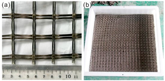
Figure 1.
Basalt fiber grid material and sample preparation: (a) Basalt fiber grid; (b) layered pouring.

Table 1.
Physical and mechanical properties of basalt fiber grid.
2.2. Sample Preparation and Testing Methods
For this study, C30-grade concrete (mix proportion detailed in Table 2) was employed to fabricate three 150 mm × 150 mm × 150 mm cubic specimens in accordance with the CECS 13:2009 Standard. The 28-day compressive strength was tested, yielding an average value of 32.05 MPa. Four 600 mm × 600 mm × 100 mm two-way slab specimens (Table 3) were prepared for finite element model development and validation. These comprised one plain concrete control specimen and three fiber-grid-reinforced specimens with varying grid layers, fabricated using a layered casting technique (Figure 1b). An additional four identical-dimension specimens were produced for regression analysis validation, including two single-layer and two double-layer grid-reinforced slabs. Taking specimen N90-1 as an example, the construction process involved (1) casting a 20 mm thick concrete base layer, (2) placing the grid levelly, and (3) repeating the procedure for subsequent layers. Following EFNARC guidelines, all specimens were demolded 24 h post casting and subsequently cured for 28 days under standard temperature and humidity conditions [25].
Table 2.
Concrete mix proportions (kg/m3).
Table 3.
Specimen list.
During testing, specimens were secured within a square rigid frame welded from structural steel (Figure 2). A 100 mm × 100 mm localized uniform load was applied to the central region using a loading head equipped with integrated displacement and load sensors. Displacement-controlled loading was implemented at a constant rate of 1 mm/min until either the load value dropped below 0.1 kN or the mid-span deflection reached 25 mm, at which point the test was terminated.
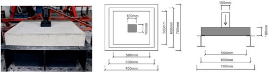
Figure 2.
Four-sided simply supported test device for two-way concrete slab.
3. Numerical Model
3.1. Model Establishment
In finite element analysis, the rationality of the model significantly impacts the accuracy of the computational results. This study established a numerical model of basalt-fiber-grid-reinforced concrete two-way slabs using ANSYS 2023 R1 software (ANSYS Inc., Canonsburg, PA, USA). The specimen geometry was 600 mm × 600 mm × 100 mm (length × width × height), with a loading indenter model of 100 mm × 100 mm × 25 mm and a base featuring an I-beam cross-section. Line-body models (circular cross-section, 1 mm diameter) were uniformly distributed along the length and width within the concrete slab and coupled to the main structure through shared nodes. The meshing strategy was as follows: hexahedral elements (25 mm size) for the concrete slab and indenter, and tetrahedral elements (50 mm size) for the base. The detailed model configuration is shown in Figure 3.
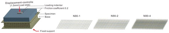
Figure 3.
Finite element model.
This study adopts a decoupled modeling framework where the concrete matrix and basalt fiber grid are independently modeled: The concrete is simulated using SOLID185 (a 3D 8-node structural solid element capable of modeling complex constitutive behaviors such as plasticity, creep, hyperelasticity, and both nearly incompressible elastoplastic and fully incompressible hyperelastic materials). The basalt fiber mesh is reinforced via REINF264 (a reinforcement element kinematically coupled to the host matrix). Material parameters are calibrated based on uniaxial compressive/tensile constitutive curves of concrete and fiber tensile behavior, including critical values.
3.2. Material Parameters and Constitutive Relationships
The material parameters adopted in the numerical model of this study are as follows: the elastic modulus of C30 concrete matrix is 30,000 MPa with a Poisson’s ratio of 0.2; the elastic modulus of structural steel is 210,000 MPa with a Poisson’s ratio of 0.3; and the elastic modulus of basalt fiber mesh is 72,000 MPa with a Poisson’s ratio of 0.23. For the constitutive model of concrete, the Menetrey–Willam constitutive model (MWC model) is selected, which integrates a yield model and a softening model. The MWC model is developed based on Willam–Warnke theory. While the Willam–Warnke constitutive model can accurately describe the mechanical behavior of concrete before reaching the plastic limit, it fails to account for the post-plastic-limit softening stage. The MWC model addresses this limitation by refining the definition of the yield surface and the treatment of hardening/softening curves.
Extensive research has demonstrated the remarkable applicability of the Menetrey–Willam constitutive model (MWC) in concrete material simulations. Notable examples include the following: Ahmed M. Yassin et al. successfully predicted the flexural performance of polyethylene-fiber-reinforced ultra-high-performance engineered cementitious composite beams by coupling the MWC model with the HSD6 softening model, with experimental validation confirming the model’s high accuracy [31]. Žiga Unuk et al. conducted three-point bending tests on notched-polymer-fiber-reinforced concrete prisms using a combined approach of nonlinear semi-numerical analysis and finite element simulation; their inverse analysis based on the MWC model yielded load–displacement curves that exhibited excellent agreement with experimental results, particularly in characterizing tensile strength properties [32]. Zheng et al. demonstrated that the MWC model could effectively control the prediction errors of axial strain within 8% for both passively confined (stirrup-confined) and actively confined (steel-tube-confined) specimens, exhibiting outstanding simulation reliability [33].
The Menetrey–Willam constitutive model requires key input parameters including strength parameters, dilation angle, and hardening/softening model options (supporting HSD2 exponential softening and HSD6 linear softening). During softening model selection, we systematically evaluated material softening models based on ANSYS official technical documentation (ANSYS Help Documentation). The HSD6 linear softening model effectively simulates concrete’s differential responses under tension and compression, accurately characterizing the post-peak stress degradation with increasing deformation. Compared to the HSD2 exponential softening model, the HSD6 model features simpler linear formulation with lower computational demand, resulting in faster solution speed and improved convergence—particularly advantageous for large-scale parametric studies. Moreover, there are fewer of its parameters, which are also physically more interpretable. The reliability of HSD6 linear softening has been substantiated by prior research. For instance, Yassin et al. employed this model in their parametric study on the flexural behavior of polyethylene-fiber-reinforced ultra-high-performance engineered cementitious composite beams, validating its effectiveness and accuracy in damage analysis [31]. Based on these theoretical analyses and empirical evidence, this study adopts the HSD6 linear softening model (Figure 4a,b).
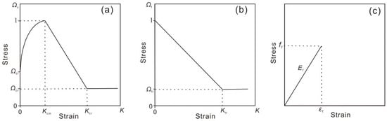
Figure 4.
Constitutive curves of experimental materials. (a) Uniaxial compression constitutive curve of concrete; (b) uniaxial tension constitutive curve of concrete; (c) tensile constitutive curve of basalt fiber grid.
Basalt fiber is an inorganic material produced by melting natural basalt rock and drawing it into filaments. With an elastic modulus ranging from 70 to 110 GPa, this high stiffness enables basalt fibers to exhibit predominantly elastic deformation with negligible plastic deformation under loading. Uniaxial tensile tests on basalt fiber grids revealed characteristic mechanical behavior: (1) a linear stress–strain relationship obeying Hooke’s Law during the elastic phase; (2) brittle fracture occurring at critical strains (1.54–1.77%) without observable plastic deformation; and (3) an abrupt stress drop upon reaching ultimate strength. These findings confirm that basalt fiber grids behave as typical linear elastic materials, demonstrating fully recoverable elastic deformation until brittle fracture—consistent with their intrinsic material properties. Therefore, we model basalt fiber grids as elastic materials, approximating their fracture behavior through maximum tensile strain threshold and material degradation indices [20], with the constitutive relationship shown in Figure 4c. Based on experimental validation and safety considerations, the maximum failure strain threshold is set at 0.015.
The constitutive model parameters were determined in accordance with the Chinese “Code for Design of Concrete Structures” (GB 50010-2010 [34]) and with reference to the recommended parameter settings for the Menetrey–Willam constitutive model in the ANSYS official material library, thereby ensuring both theoretical rationality and engineering applicability.
Numerical simulation input values in this study:
- (plastic strain at peak point): 0.00164;
- (compressive plastic strain limit): 0.01;
- (relative stress at hardening initiation): 0.35;
- (residual relative compressive stress): 0.1;
- (tensile plastic strain limit): 0.01;
- (residual relative tensile stress): 0.1.
3.3. Boundary Conditions and Analysis Settings
This study defines the contact relationship between the indenter, base, and concrete as frictional contact (friction coefficient of 0.2) [35], with fixed support applied at the base bottom. Regarding the loading scheme, although laboratory tests employed continuous uniform loading, numerical simulation requires decomposing the total load into incremental loading steps. Accordingly, this study simulated the loading application process through displacement-controlled loading, implementing a total of 10 loading steps with a displacement control rate of 1.5 mm per loading step. Analysis configurations include enabling automatic time stepping, activating force and displacement convergence criteria (both with 5% tolerance), and implementing linear search algorithms. To address the insufficiency of ANSYS default iterations (25 cycles), APDL command snippets (e.g., NEQIT modification) are embedded to increase maximum iterations to 50 cycles, thereby enhancing computational stability.
4. Experimental Results and Numerical Simulation
4.1. Mechanical Properties
Experimental and numerical simulation results of basalt-fiber-grid-reinforced concrete two-way slabs (Table 4) demonstrate that both ultimate load capacity and mid-span deflection significantly improve with increasing grid layers. In experimental tests, specimens with 1, 2, and 4 grid layers achieved ultimate loads of 47.74 kN, 51.50 kN, and 69.25 kN, respectively, representing 5.97%~53.72% enhancements compared to plain concrete (45.05 kN), while mid-span deflections increased from 3.4 mm to 4.92 mm with 54.55%~123.64% improvements over plain concrete (2.20 mm). Notably, in fiber-grid-reinforced concrete specimens, the ultimate load does not necessarily equate to the failure load. The ultimate load corresponds to the maximum value in the load–deflection curve, whereas the failure load represents the load level at which the specimen initiates load-bearing capacity degradation, manifested by localized fiber grid fracture and a distinct inflection point in the post-peak curve (Figure 5). Experimental data demonstrate that for single- and double-layer-reinforced specimens, the failure loads measured 46.74 kN and 50.28 kN, respectively, marginally lower than their corresponding ultimate loads (47.74 kN and 51.50 kN). This discrepancy arises from the damage progression mechanism: when the central grid region attains its maximum tensile strain (below the fiber’s ultimate tensile strain capacity), the load reaches its peak. However, stress redistribution induces rapid crack propagation preferentially in peripheral regions rather than the central zone, causing initial fiber fracture at specimen edges. Consequently, the ultimate and failure loads exhibit non-coincidence. In contrast, quadruple-layer specimens demonstrate synchronized ultimate and failure loads due to enhanced stress distribution uniformity, enabling central fibers to reach ultimate tensile strain and fracture preferentially. Plain concrete specimens, devoid of fiber-reinforced ductility, exhibit immediate brittle failure post-peak load, resulting in identical ultimate and failure loads. The mechanical performance exhibits progressive enhancement with increasing grid layers, as evidenced by both elevated failure loads and improved mid-span deflection capacity. These findings substantiate that basalt fiber grids significantly enhance the mechanical properties of two-way concrete slabs, with reinforcement effectiveness exhibiting a positive correlation with layer quantity.
Table 4.
Experimental and numerical simulation results.
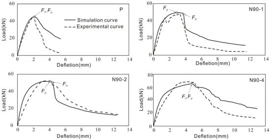
Figure 5.
Load–deflection curve comparison.
The simulated results yielded ultimate loads and corresponding deflections of 49.796 kN, 51.716 kN, and 66.401 kN and 3.13 mm, 3.69 mm, and 4.85 mm, respectively. Comparative analysis between experimental and numerical values demonstrated satisfactory agreement (error < 10%, Table 4): the ratios of ultimate load, mid-span deflection at ultimate load, failure load, and mid-span deflection at failure load had ranges of 0.96–1.04, 0.91–0.99, 0.92–1.42, and 1.02–1.09, respectively (Figure 6). Furthermore, the load–deflection curves exhibited remarkable consistency in both trend and magnitude (Figure 5), thereby validating the reliability of the numerical model.
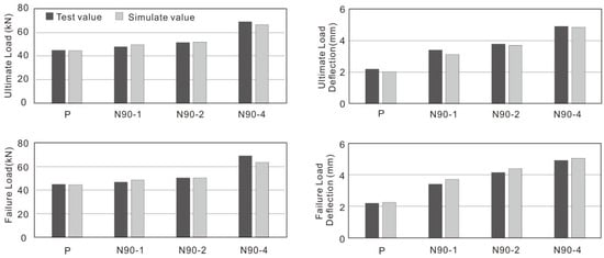
Figure 6.
Comparison of experimental and numerical simulation results.
4.2. Specimen Deformation and Failure Characteristics
Finite element simulations of two-way slab deformation reveal that the mid-span compression zone exhibits maximum deflection under incremental loading steps, with corner warping phenomena highly consistent with experimental observations (Figure 7). Upon reaching the elastic strain limit of concrete in the numerical model, distinct plastic deformation stages emerge across specimen regions: Plain concrete model (P)—Radiating band-shaped plastic deformation zones (primary plastic bands) forming at the bottom center, accompanied by a single vertical plastic deformation band along the side height (Figure 8 and Figure 9). Single-layer basalt fiber grid model (N90-1)—Eight plastic deformation bands (4 primary + 4 secondary) develop at the bottom, with primary bands aligning directionally with the P model but exhibiting increased width, while secondary bands adopt symmetric distributions. A dual-band structure emerges on the sides, and localized point-like plastic deformation zones appear on the top surface at the 10th loading step (Figure 8 and Figure 9). Double-layer basalt fiber grid model (N90-2)—Plastic deformation bands maintain morphological similarity to N90-1 but demonstrate significant width expansion on both bottom and side surfaces, accompanied by enlarged top-surface plastic deformation areas (Figure 8 and Figure 9).
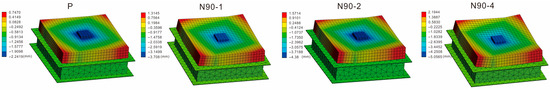
Figure 7.
Numerical simulation of directional deformation nephogram (Z-axis orientation).
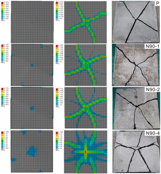
Figure 8.
Numerical plastic strain contours (top/bottom surfaces, (left/middle)) and experimental failure characteristics of specimen (bottom surface, (right)).
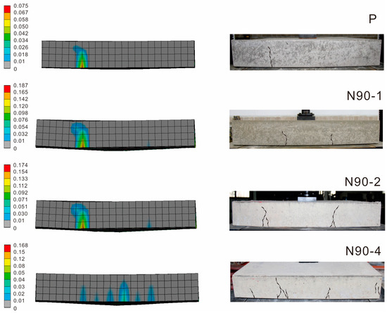
Figure 9.
Numerical plastic strain contours on specimen side surface.
Quadruple-layer basalt fiber grid model (N90-4)—Multi-directional primary plastic deformation bands (longitudinal, transverse, and diagonal) form at the bottom, multiple longitudinal bands develop on the sides, and top-surface plastic deformation zones evolve from discrete points to continuous planar distributions (Figure 8 and Figure 9).
Comparative analysis of numerical plastic strain contours and experimental failure patterns (Figure 8 and Figure 9) demonstrates strong spatial coupling between simulated plastic deformation bands and actual crack distributions in terms of quantity and orientation. This correlation validates the finite element model’s capability to characterize structural failure modes, suggesting its efficacy as a reliable alternative to physical testing for evaluating damage evolution mechanisms.
4.3. Deformation and Failure Characteristics of Basalt Fiber Grid
4.3.1. Distribution Features of Equivalent Elastic Strain
Figure 10 (4× magnification) reveals that both single-layer (N90-1) and double-layer (N90-2) basalt fiber grid models exhibit similar spatial distributions in equivalent elastic strain nephograms. Specifically, eight radiating band-shaped elastic deformation zones develop outward from the central area, with four primary elastic strain bands (wider) alternating with four secondary elastic strain bands (narrower). Notably, the width of the primary elastic strain bands in the double-layer grid increases by approximately 20% compared to the single-layer model. The four-layer grid (N90-4) demonstrates significant differences: its elastic strain area expands by 2~3 times relative to the single-layer model, and the strain gradient distribution becomes more continuous (Figure 10), indicating that increasing the number of fiber grid layers enhances strain distribution uniformity.
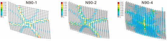
Figure 10.
Numerical simulation contour of equivalent elastic strain in basalt fiber grid.
4.3.2. Evolution of Equivalent Stress
Based on the elastic material assumption with a maximum failure strain threshold of 0.015, Figure 11 (4× magnification) illustrates the equivalent stress transfer mechanisms for grids with varying layers: Single/Double-Layer Models—Both exhibit eight band-shaped stress zones (four primary and four secondary), where the principal stress directions align closely with the elastic strain bands (Figure 11). Gray areas within the strain bands in the stress nephograms indicate regions where the fiber grids have reached the strain threshold and failed. The failure area in the double-layer model decreases by approximately 20% compared to the single-layer model. Four-Layer Model—The stress distribution transitions from discrete band-shaped patterns to continuous planar patterns, with the effective load-bearing area exceeding twice that of the single-layer model and a significant reduction in the proportion of failed regions (Figure 11).
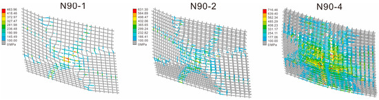
Figure 11.
Numerical simulation contour of equivalent stress in basalt fiber grid.
Numerical simulations demonstrate that increasing grid layers fundamentally alters load transfer pathways (Figure 10 and Figure 11). The four-layer grid disperses loads over a larger area (coverage > 70%) through multi-layer, multi-directional fiber interactions, delaying grid failure. Combined with mechanical performance simulations, this suggests that structural load-bearing capacity improves in direct correlation with the volume fraction of fibers actively participating in load transfer. These findings validate that the multi-layer composite structure of the basalt fiber grid optimizes stress redistribution during concrete matrix failure.
5. Model Application
This study established numerical models of plain concrete and basalt-fiber-grid-reinforced concrete with varying layers based on the ANSYS finite element analysis platform. The simulation results demonstrated that increasing the mesh layers significantly enhances structural ultimate load and mid-span deflection, while altering failure modes and stress distribution characteristics. A comparison between experimental results and numerical simulations revealed good consistency, with matching load-deflection curve patterns, thereby validating the effectiveness of the numerical model. The plastic strain distribution in the numerical model strongly correlated with the quantity and orientation of cracks observed in tested specimens, confirming the model’s capability to characterize failure modes. Consequently, the parametric analysis framework derived from this model can effectively investigate variables such as reinforcement layer count and mesh position, providing theoretical support for optimizing fiber-grid-reinforced concrete structural designs.
5.1. Position Effect of Single-Layer Fiber Grid in Concrete Slabs
A systematic study on the positional effects of a single-layer basalt fiber grid in concrete slabs was conducted through parametric analysis with nine numerical models. In the model setup, the initial position of the fiber grid was 10 mm from the bottom of the concrete, and it was then incrementally shifted upward in 10 mm gradients. The simulated load–deflection behavior is shown in Figure 12. As the fiber grid moved away from the tensile zone (bottom), the specimen’s peak load decreased significantly, accompanied by a reduction in characteristic displacement at peak load. When the grid reached 80 mm (fully within the compressive zone), its reinforcing effect became negligible, and the load–displacement curve closely resembled that of plain concrete.
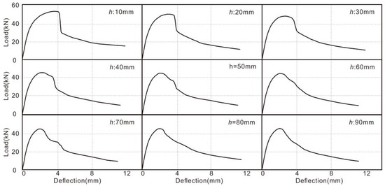
Figure 12.
The simulated load–deflection curve for basalt-fiber-grid-reinforced concrete with single-layer reinforcement (h = grid position, mm).
Based on nine sets of numerical simulation data, a quantitative relationship model between the position of a single-layer basalt fiber grid and the mechanical performance parameters of a two-way slab was established using nonlinear regression methods. Fitting curves (Figure 13) and nonlinear regression equations were constructed for
Fp = 56,829.87 − 468.2787h + 6.07326h2 − 0.026173h3 (R2 = 0.999)
δp = 4.675 − 0.1024h + 0.00013h2 − 0.000005h3 (R2 = 0.991)
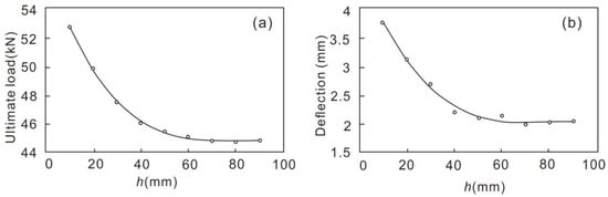
Figure 13.
Regression curves of single-layer basalt fiber grid concrete based on simulation. (a) Grid position vs. ultimate load; (b) grid position vs. deflection at ultimate load.
In the formula,
- Fp: Ultimate load (kN);
- δp: Mid-span deflection at ultimate load (mm);
- h: Fiber mesh position (distance from bottom surface, mm).
The goodness-of-fit indicators for the two nonlinear regression equations reached 0.999 and 0.991, demonstrating that the regression models meet precision requirements.
5.2. Position Effect of Double-Layer Fiber Grid in Concrete Slabs
This study further investigates the mechanical response characteristics of double-layer basalt-fiber-grid-reinforced concrete structures. A systematic analysis was conducted through 72 numerical models, employing a variable control method with fixed h1 (distance of the first grid layer from the bottom surface) and varying h2 (position of the second grid layer). The simulated load–deflection behavior is shown in Figure 14. When h1 + h2 ≤ 60 mm, the dual grids exhibit significant collaborative behavior. The peak load shows nonlinear growth as the sum of h1 + h2 decreases, accompanied by increased peak deflection. When both h1 and h2 exceed 60 mm (h1 ≥ 60 mm and h2 ≥ 60 mm), the positional difference between the dual grids minimally influences the load–deflection curve morphology. The load-bearing capacity gradually converges to that of plain concrete. This pattern indicates that the structural reinforcement effect depends nonlinearly on the relative positioning of grid layers, with optimal synergy occurring within specific spatial thresholds.
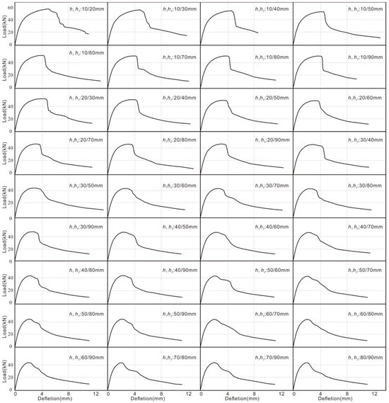
Figure 14.
The simulated load–deflection curve of double-layer basalt fiber grid concrete.
Based on 72 numerical models (h1 and h2 denote the distances of the two grid layers from the bottom surface), a regression analysis was conducted to establish a quantitative relationship model between the grid positions and the mechanical performance parameters of the double-layer basalt-fiber-grid-reinforced concrete slabs. This study developed fitting surfaces (Figure 15) and nonlinear regression equations for ultimate load versus grid positions, as well as ultimate load–deflection versus grid positions:
Fp = 73.17 − 0.000028h13 + 0.00675h12 − 0.5586h1 − 0.000028h23 + 0.00685h22 − 0.5586h2 (R2 = 0.996)
δp = 8.17 − 0.0000054h13 + 0.0013h12 − 0.112h1 − 0.0000054h23 + 0.0013h22 − 0.112h2 (R2 = 0.992)
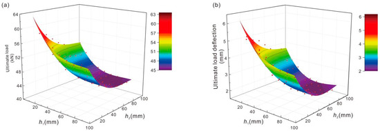
Figure 15.
Regression surfaces of double-layer basalt fiber grid concrete based on simulation. (a) Grid position vs. ultimate load; (b) grid position vs. deflection at ultimate load.
In the formula,
- Fp: Ultimate load (kN);
- δp: Mid-span deflection at ultimate load (mm);
- h1, h2: Fiber grid position (distance from bottom surface, mm).
The goodness-of-fit indices for the two nonlinear regression equations are 0.996 and 0.992, respectively, confirming the high accuracy of the regression models.
To validate the model accuracy, verification tests were conducted on concrete specimens with four distinct fiber grid configurations (single-layer at 0 mm and 10 mm positions, double-layer at 0/20 mm and 10/20 mm positions), evaluating the model’s predictive performance. As summarized in Table 5, the model demonstrated excellent reliability in ultimate load prediction, with relative errors between calculated and experimental values ranging from 1.24% to 5.25% (MAPE = 4.1%, R2 = 0.983). For deflection prediction, the model achieved a mere 3.4% error for single-layer specimens, while the maximum residual reached 0.75 mm for double-layer specimens. Further analysis revealed this discrepancy primarily originated from unaccounted interfacial slip effects between multiple grid layers in the current model.
Table 5.
Comparison of verification test results with simulation and regression analysis data.
Based on secondary development of finite element models, this study establishes regression equations for predicting the ultimate load and deflection of single-/double-layer grid-reinforced concrete, providing engineers with a rapid estimation tool that eliminates the need for complex numerical modeling. The current model exhibits high reliability in ultimate load prediction, with errors consistently below 5%. Future research will focus on incorporating interfacial slip constitutive relationships and optimizing deformation algorithms to further improve prediction accuracy, particularly for deflection estimation in multi-layer grid applications.
6. Conclusions
- This study developed a refined finite element model using the ANSYS platform, successfully reproducing both the flexural deformation patterns and grid failure mechanisms of basalt-fiber-grid-reinforced two-way concrete slabs. The model demonstrated high accuracy, with errors between experimental and simulated values for all key parameters, including ultimate load, ultimate load deflection, failure load, and failure load deflection, remaining below 10%.
- Both experiments and numerical simulations demonstrated that as the number of basalt fiber grid layers increased, the ultimate bearing capacity and mid-span deflection of the two-way slabs significantly improved. Compared to ordinary concrete slabs, the ultimate bearing capacity of slabs reinforced with 1, 2, and 4 layers of grid increased by 5.97%, 14.27%, and 53.72%, respectively, while mid-span deflection improved by 54.55%, 72.27%, and 123.64%.
- Numerical simulations revealed that increasing grid layers altered the morphology of plastic deformation zones in concrete slabs, evolving from a single primary plastic zone to multidirectional and multilevel plastic deformation bands. Concurrently, the equivalent elastic strain distribution of the basalt fiber grid became more uniform, and stress transfer pathways grew more complex, enhancing the overall structural load-bearing capacity.
- Through parametric studies using the developed numerical model, this work established quantitative relationships between grid positioning (single/double-layer configurations) and mechanical performance of two-way slabs via nonlinear regression analysis. The linear regression-predicted ultimate loads showed excellent agreement with experimental results, with relative errors controlled within 1.24–5.25%, demonstrating the model’s reliability as a rapid estimation tool for engineering applications.
This study developed finite element and regression predictive models for basalt-fiber-grid-reinforced concrete two-way slabs through integrated experimental and numerical investigations, establishing a reliable digital design tool with strong potential for practical applications to enhance design efficiency. The derived regression equations provide efficient ultimate load estimation for single/double-layer specimens, though requiring strict control of grid positioning parameters, while full numerical simulation remains recommended for multi-layer or complex scenarios. Future research directions should focus on extending validation to multi-layer grid systems, incorporating interfacial slip constitutive laws to improve post-cracking strength prediction accuracy, exploring machine learning optimization, and investigating dynamic loading adaptability to further enhance the model’s engineering applicability and predictive performance.
Author Contributions
Conceptualization, C.H.; Formal analysis, L.L.; Investigation, M.H.; Data curation, N.L.; Writing—original draft, S.J.; Writing—review & editing, C.H.; Supervision, X.L.; Funding acquisition, C.F. and W.Z. All authors have read and agreed to the published version of the manuscript.
Funding
This work was supported by the youth research fund of Lishui University (053/2022), technology project “Research and application demonstration of fiber reinforced concrete highway cover plate” (HXB-20223043), and research on key technologies for design and construction of mechanized variable-section composite piles in Lishui mountain power transmission project (KJKY20230446).
Data Availability Statement
The original contributions presented in this study are included in the article. Further inquiries can be directed to the corresponding authors.
Conflicts of Interest
Authors Chaobin Hu and Mingjian He were employed by the company Zhejiang Shankou Construction Engineering Co., Ltd. Author Weiping Zhou was employed by the company Qingtian County Transport Development and Investment Co., Ltd. The remaining authors declare that the research was conducted in the absence of any commercial or financial relationships that could be construed as a potential conflict of interest.
References
- Sim, J.; Park, C.; Moon, D.Y. Characteristics of basalt fiber as a strengthening material for concrete structures. Compos. Part B Eng. 2005, 36, 504–512. [Google Scholar] [CrossRef]
- Bhat, T.; Chevali, V.; Liub, X.; Feiha, S.; Mouritz, A.P. Fire structural resistance of basalt fibre composite. Compos. Part A Appl. Sci. Manuf. 2015, 71, 107–115. [Google Scholar] [CrossRef]
- Chen, W.S.; Hao, H.; Jong, M.; Cui, J.; Shi, Y.C.; Chen, L.; Pham, T.M. Quasi-static and dynamic tensile properties of basalt fibre reinforced polymer. Compos. Part B Eng. 2017, 125, 123–133. [Google Scholar] [CrossRef]
- Lu, Z.Y.; Xian, G.J. Resistance of basalt fibers to elevated temperatures and water or alkaline solution immersion. Polym. Compos. 2016, 39, 2385–2393. [Google Scholar] [CrossRef]
- Graupner, N.; Sarasini, F.; Müssig, J. Ductile viscose fibres and stiff basalt fibres for composite applications—An overview and the potential of hybridisation. Compos. Part B Eng. 2020, 194, 108041. [Google Scholar] [CrossRef]
- Jamshaid, A.; Mishra, R. A green material from rock: Basalt fiber—A review. J. Text. Inst. 2016, 107, 923–937. [Google Scholar] [CrossRef]
- Deng, Z.Y.; Liu, X.R.; Chen, P.; de la Fuente, A.; Zhao, Y.; Liang, N.; Zhou, X.; Du, L.; Han, Y. Basalt-Polypropylene Fiber Reinforced Concrete for Durable and Sustainable Pipe Production. Part 2: Numerical and Parametric Analysis. Struct. Concr. 2022, 23, 328–345. [Google Scholar] [CrossRef]
- Deng, Z.Y.; Liu, X.R.; Yang, X.; Liang, N.H.; Yan, R.; Chen, P.; Miao, Q.X.; Xu, Y.H. A Study of Tensile and Compressive Properties of Hybrid Basalt-Polypropylene Fiber-Reinforced Concrete under Uniaxial Loads. Struct. Concr. 2021, 22, 396–409. [Google Scholar] [CrossRef]
- Zhang, M.M. Research on the Mechanical Performance of Basalt Textile Reinforced. Ph.D. Thesis, Hunan University, Changsha, China, 2017. [Google Scholar]
- Ding, Y.N.; Wang, Q.X.; Pacheco-Torgal, F.; Zhang, Y.L. Hybrid effect of basalt fiber textile and macro polypropylene fiber on flexural load-bearing capacity and toughness of two-way concrete slabs. Constr. Build. Mater. 2020, 261, 119881. [Google Scholar] [CrossRef]
- Wang, Q.X.; Ding, Y.N.; Randl, N. Investigation on the alkali resistance of basalt fiber and its textile in different alkaline environments. Constr. Build. Mater. 2020, 263, 121670. [Google Scholar] [CrossRef]
- D’Anna, J.; Amato, G.; Chen, J.; Minafò, G.; La Mendola, L. Effects of different test setups on the experimental tensile behaviour of basalt fibre bidirectional grids for FRCM composites. Fibers 2020, 8, 68. [Google Scholar] [CrossRef]
- Hutaibat, M.; Ghiassi, B.; Tizani, W. Bond behaviour of prestressed basalt textile reinforced concrete. Constr. Build. Mater. 2024, 438, 137309. [Google Scholar] [CrossRef]
- Gopinath, A.; Murthy, A.R.; Iyer, N.R.; Prabha, M. Behaviour of reinforced concrete beams strengthened with basalt textile reinforced concrete. J. Ind. Text. 2015, 44, 924–933. [Google Scholar] [CrossRef]
- Deng, Z.C.; Li, Q. Bending properties of ultra-high performance concrete two-way slabs reinforced with hybrid meshes. J. Tianjin Univ. Sci. Technol. 2024, 57, 301–310. [Google Scholar]
- Celauro, C.; Praticò, F.G. Asphalt mixtures modified with basalt fibres for surface courses. Constr. Build. Mater. 2018, 170, 245–253. [Google Scholar] [CrossRef]
- Hughes, E.; Das, S.; Van Engelen, N.; Lawn, D. Concrete girders retrofitted with basalt fibre fabric—A feasibility study using lab tests and field application. Eng. Struct. 2021, 238, 112223. [Google Scholar] [CrossRef]
- Wei, C.Z.; Zhang, M.; Li, G.; Jiang, Y.J.; Ren, J.L. Evaluation and application of basalt fiber reinforcement mesh for improving pavement interlayer bonding property via a new approach of interlayer shear test of composite plate. Constr. Build. Mater. 2025, 469, 140518. [Google Scholar] [CrossRef]
- Lin, W.W.; Lin, M.; Gu, K.P.; Wang, Q.Q. Application of basalt fiber products in reinforcement and repair of old wharves. Port Waterw. Eng. 2025, 1, 193–198. [Google Scholar]
- Chen, X.; Yan, Z.G. Compressive behaviour of concrete column confined with basalt textile reinforced ECC. Eng. Struct. 2021, 243, 112651. [Google Scholar] [CrossRef]
- Al-Oraimi, S.K.; Seibi, A.C. Mechanical characterisation and impact behaviour of concrete reinforced with natural fibres. Compos. Struct. 1995, 32, 165–171. [Google Scholar] [CrossRef]
- Ibrahim, S.S.; Kandasamy, S.; Pradeepkumar, S.; Bose, R.S.C. Effect of discrete steel fibres on strength and ductility of FRP laminated RC beams. Ain Shams Eng. J. 2020, 12, 1329–1337. [Google Scholar] [CrossRef]
- Li, D.; Ding, Y.Y. Effect of steel fiber on biaxial flexural property of TRC with basalt fiber mesh in slab test. Acta Mater. Compos. Sin. 2019, 36, 482–490. [Google Scholar]
- Hu, C.B.; Liu, X.R.; Jin, S.; He, M.J.; Li, L.P.; Liang, N.H.; Fu, C.R. Study on the hybrid effect of chopped fiber and basalt fiber textile on the flexural behavior of two-way concrete slabs. Case Stud. Constr. Mater. 2025, 23, e05027. [Google Scholar] [CrossRef]
- EFNARC. European Specification for Sprayed Concrete; Loughborough University Press: Loughborough, UK, 1996; ISBN 0-952-24831-X. [Google Scholar]
- CECS 13:2009; Standard for test methods of fiber reinforced concrete. China Planning Press: Beijing, China, 2009.
- Kim, H.Y.; You, Y.J.; Ryu, G.S.; Ahn, G.H.; Koh, K.T. Concrete slab-type elements strengthened with cast-in-place carbon textile reinforced concrete system. Materials 2021, 14, 1437. [Google Scholar] [CrossRef] [PubMed]
- Zhang, H.Y.; Liu, H.Y.; Kodur, V.; Li, M.Y.; Zhou, Y. Flexural behavior of concrete slabs strengthened with textile reinforced geopolymer mortar. Compos. Struct. 2022, 284, 115220. [Google Scholar] [CrossRef]
- Deng, Z.C.; Xia, Q.; Gong, M.G.; Xu, J.L. Flexural strengthening of two-way RC slabs with textile reinforced mortar: Experimental study and calculation model. KSCE J. Civ. Eng. 2023, 27, 5268–5280. [Google Scholar] [CrossRef]
- Hussein, O.H.; Ibrahim, A.M.; Abd, S.M.; Najm, H.M.; Shamim, S.; Sabri, M.M.S. Hybrid effect of steel bars and PAN textile reinforcement on ductility of one-way slab subjected to bending. Molecules 2022, 27, 5208. [Google Scholar] [CrossRef] [PubMed]
- Yassin, A.M.; Hafez, M.A.; Mohie Eldin, M. The flexural behavior of reinforced ultra-high performance engineering cementitious composite (UHP-ECC) beams fabricated with polyethylene fiber (numerical and analytical study). Buildings 2024, 14, 3484. [Google Scholar] [CrossRef]
- Unuk, Ž.; Kuhta, M. Nonlinear semi-numeric and finite element analysis of three-point bending tests of notched polymer fiber-reinforced concrete prisms. Appl. Sci. 2024, 14, 1604. [Google Scholar] [CrossRef]
- Zheng, B.T.; Teng, J.G. A plasticity constitutive model for concrete under multiaxial compression. Eng. Struct. 2022, 251, 113435. [Google Scholar] [CrossRef]
- GB 50010-2010; Code for Design of Concrete Structures. China Architecture & Building Press: Beijing, China, 2010.
- Xu, Y.Y. Experimental Study on Bond Anchorage Behavior of Deformed Steel Bars in Concrete. Ph.D. Thesis, Peking University, Beijing, China, 1990. [Google Scholar]
Disclaimer/Publisher’s Note: The statements, opinions and data contained in all publications are solely those of the individual author(s) and contributor(s) and not of MDPI and/or the editor(s). MDPI and/or the editor(s) disclaim responsibility for any injury to people or property resulting from any ideas, methods, instructions or products referred to in the content. |
© 2025 by the authors. Licensee MDPI, Basel, Switzerland. This article is an open access article distributed under the terms and conditions of the Creative Commons Attribution (CC BY) license (https://creativecommons.org/licenses/by/4.0/).