Article

Aerodynamic Loading and Wind-Induced Vibration Characteristics of Bridge Girders with Typical Asymmetric Configurations

1
Postdoctoral Research Station, Chongqing Jiaotong University, Chongqing 400056, China
2
Postdoctoral Workstation, CREEC (Chongqing) Survey, Design and Research Co., Ltd., Chongqing 400056, China
3
Institute of Science and Technology, China Railway Eryuan Engineering Group Co., Ltd., Chengdu 610031, China
4
Wind Engineering Key Laboratory of Sichuan Province, Southwest Jiaotong University, Chengdu 610031, China
*
Author to whom correspondence should be addressed.
Buildings 2025, 15(16), 2824; https://doi.org/10.3390/buildings15162824
Submission received: 24 June 2025 / Revised: 20 July 2025 / Accepted: 23 July 2025 / Published: 8 August 2025
(This article belongs to the Special Issue Wind Load Effects on High-Rise and Long-Span Structures: 2nd Edition)

Abstract

The bridge girder’s aerodynamic configuration substantially governs its aerodynamic loading and wind-induced vibration characteristics. Extensive research has been performed to optimize the configuration of girders and implement aerodynamic measures to enhance the bridge’s wind resistance. In some practical bridge engineering projects, the aerodynamic configuration of the bridge girder is asymmetric. However, studies investigating the aerodynamic properties of asymmetric girders are limited. In this paper, the aerodynamic loading and vibration characteristics of the Π-shaped girders and box girders with asymmetric bikeways are experimentally studied. Through an extensive series of wind tunnel experiments, the static wind loading coefficients, flutter derivatives, vortex-induced vibration (VIV) responses, and the critical flutter velocities are compared across varying wind direction angles (WDAs). The experimental results demonstrate that the asymmetric girder configurations have different characteristics in both the static wind loading coefficient and flutter derivative in different WDAs. The influence of WDAs on the above-mentioned aerodynamic force coefficients of the asymmetric Π-shaped girder is more pronounced than that on the asymmetric box girder. For the asymmetric Π-shaped girder, the heaving VIV responses at a 0° WDA are smaller than those at a 180° WDA, but the torsional VIV responses at a 0° WDA are larger. Experimental results for critical flutter velocities indicate that the flutter performance at a 0° WDA is better than that at a 180° WDA, especially at positive angles of attack (AOAs) for the two types of asymmetric bridge girders.

1. Introduction

Due to their large span length, low stiffness, and small damping ratios, long-span bridges exhibit significant vulnerability to multiple wind-induced vibration phenomena, including vortex-induced vibration (VIV) [1,2,3,4], buffeting [5,6,7,8], and flutter [9,10,11,12]. During the bridge design process, a critical focus on wind-induced vibration effects is imperative to ensure that bridge responses do not exceed the limits specified in the design codes. This ensures the bridge design meets wind load safety standards and fulfills normal service comfort criteria. Consequently, systematic research into the aerodynamic behavior of bridge girders constitutes a fundamental requirement.
Modern bridge girders are characterized by their diverse forms and complex aerodynamic shapes [13,14]. Generally, in the initial stage of bridge design, the aerodynamic characteristics of the girder are difficult to meet the wind resistance requirements of the bridge [15,16,17]. Therefore, different strategies are needed to optimize the aerodynamic performance of bridges. Among wind-induced instabilities in bridges, VIV and flutter are the most common issues for bridge girders [18,19,20]. For different types of girders, many scholars have proposed a wide range of aerodynamic vibration control measures to optimize the flutter and VIV performance of bridges.
There are various aerodynamic measures for improving bridge flutter performance, the most common of which include optimizing the shape of the wind fairings, installing vertical stabilizers, horizontal flaps, and wind barriers, and central slots in the main girder. Tang et al. [21] examined the flutter characteristics of bridge girders at large AOAs. The study revealed that appropriately designed wind fairings can significantly improve the bridge’s flutter under large AOAs. Furthermore, results demonstrated that upper central stabilizers serve as particularly effective measures to improve bridge flutter resistance. Ueda et al. [22] investigated the flutter mitigation mechanisms of central stabilizers. The study demonstrated that central stabilizers suppress flutter through two primary mechanisms: (1) airflow reseparation at the stabilizer’s lower edge and (2) ventilation flow through the girder’s central grating. Yang et al. [23] examined the impacts of vertical central stabilizers on the twin-box girder’s flutter characteristics, considering various slot width ratios. Mei et al. [24] investigated the mechanism by which the stabilizer suppresses the bridge’s flutter via flutter experiments and theoretical coupled flutter analysis. Li et al. [25] and Sun et al. [26] studied the influences of upper and lower stabilizers on the nonlinear flutter response of a bridge with a double-deck truss girder. Yang et al. [27] investigated the wind barrier’s influence mechanism on the box girder’s flutter performance. Through detailed analysis of flutter derivative contributions and modal participation characteristics, the study elucidated the comprehensive evolution of the flutter process under the wind barrier’s influence. In addition to the passive aerodynamic measures mentioned above, some scholars have proposed active flutter control measures to improve the bridge’s flutter. Kobayashi and Nagaoka [28] installed control wings on a bridge girder to suppress the flutter. Zhuo et al. [29] developed a theoretical framework for active flutter control based on a girder system equipped with adjacent active control flaps. Wang et al. [30] developed an analytical framework to elucidate the flutter control mechanism of the deck-flap system using computational fluid dynamics (CFD) and quantified the contribution of active flaps’ aerodynamic damping. In recent years, the increase in computing power has led to widespread attention on the application of CFD and AI in revealing the flow fields around bridges and bluff bodies, as well as in the prediction of aerodynamic forces [31,32,33]. Tongaria et al. [34] proposed a time domain framework to determine the critical flutter velocity of a bridge deck from CFD-based aeroelastic simulations followed by system identification. Verma et al. [35] developed an aeroelastic surrogate model trained with data extracted from forced-vibration CFD simulations to simulate frequency-dependent self-excited forces. This model is applicable to diverse bridge deck geometries, including streamlined and bluff configurations. Zhang et al. [36] proposed a time-domain nonlinear method for three-dimensional (3D) full-bridge flutter analysis based on deep learning, which provides an important reference for accurately evaluating the nonlinear flutter performance of bridges. Kavrakov et al. [37] presented data-driven aeroelastic analyses of structures in turbulent wind conditions using enhanced Gaussian processes with aerodynamic priors.
In the past few decades, aerodynamic optimization studies for bridge VIV mitigation have attracted widespread attention from scholars. Nagao et al. [38] examined the influence of handrail configurations on the deck’s VIV characteristics through pressure measurements and smoke visualization techniques. The results indicated that the type and location of the handrails significantly affect VIV responses. Larose et al. [39] investigated the guide vane’s efficacy in suppressing VIV of the Stonecutters Bridge. Their findings demonstrated that corner-mounted guide vanes on bridge decks enhance the acceleration of the inner wind flow, consequently attenuating the strength of downstream vortices. Yang et al. [40] studied different VIV mitigation measures for twin-box girders, identifying wind barriers as the most effective solution. Xu et al. [41] conducted a comprehensive investigation into the torsional VIV mechanisms of box girder bridge decks using synchronized pressure measurements. The results demonstrated that torsional VIV can be effectively mitigated through optimized spoiler configurations, where strategically generated vortices interact to mitigate VIV responses. Li et al. [42] investigated the streamlined deck’s VIV, revealing that handrail porosity significantly affects VIV characteristics. Ma et al. [43] studied the twin-box girder bridge’s VIV behavior and the effects of grid plates on suppressing VIV. Yan et al. [44] explored the influence of grid-like and non-grid-like handrails on the heaving VIVs of a streamlined deck. The results demonstrated that there is a difference between the aerodynamic behavior of the bridge girders with grid-like handrails and non-grid-like handrails. Li et al. [45] examined the efficacy of guide vanes in mitigating VIV of a streamlined deck and explored the mitigation mechanisms through CFD simulations. Duan et al. [46] developed a numerical approach that integrates both free and forced vibration analyses to investigate the VIV behavior of a twin-box girder section and explored the mechanisms underlying VIV. Montoya et al. [47] proposed an experimental data-driven adaptive surrogate-based optimization framework using experimental data to systematically identify optimal deck geometries that satisfy VIV constraints while minimizing bridge construction costs. Wang et al. [48] developed a novel data-driven model to predict the time history of the dynamic response of VIV events of long-span bridges. Li et al. [49] developed a CFD-wind tunnel interactive digital twin framework for precise VIV response prediction in bridge decks, demonstrating its efficacy for accurate and efficient bridge vibration analysis.
The above-reviewed literature all involves the installation of various aerodynamic measures to optimize bridge girder configurations, thereby enhancing the aerodynamic stability of long-span bridges. This demonstrates that the bridge girders’ configuration of the main girder critically governs their wind-resistant performance. In actual bridge engineering, some bridges are equipped with a one-sided bikeway on one side of the girder to meet the needs of cyclists, such as the Gerald Desmond Bridge (United States) and the Hålogaland Bridge (Norway). The asymmetric bikeway induces aerodynamically asymmetric characteristics in the bridge’s main girder. While existing research has extensively investigated the wind-resistant performance of symmetric bridge girders, studies addressing asymmetric girder configurations remain notably limited. Wang et al. [50] investigated the VIV behavior and mechanism of an asymmetrical composite beam cable-stayed bridge by wind tunnel experiments and CFD simulations. Yang et al. [51] investigated the aerodynamic instability performance of twin box girders of long-span bridges. They found that long-span twin-box girders with asymmetric wind fairings display distinct slot-width-ratio-dependent flutter characteristics, including optimal performance conditions absent in symmetric configurations. Cong et al. [52] examined aerodynamic shape effects on cable VIV nonlinear dynamics using theoretical analysis and CFD simulations. Their results demonstrate that cable cross-sectional variations substantially alter aerodynamic behavior, with asymmetric configurations exhibiting pronounced sensitivity to wind attack angles.
Asymmetric girders exhibit different aerodynamic characteristics under different incoming WDAs. However, the aerodynamic behavior and flow-induced vibration mechanisms of asymmetric girders under different incoming wind direction angles (WDAs) are not yet well understood. To address this research gap, the present study conducts experimental investigations of the aerodynamic behavior of two distinct asymmetric bridge girder configurations: a Π-shaped girder and a box girder. Through extensive wind tunnel tests, the static wind loading coefficients, flutter derivatives, VIV responses, and critical flutter velocities under different incoming WDAs are compared and analyzed. This study provides design references and aerodynamic insights for wind-resistant design of large-span asymmetric-girder bridges.

2. Research Background and Experimental Setup

2.1. Details of the Bridges

Figure 1 depicts the cable-stayed bridge’s general arrangement and the asymmetric Π-shaped girder cross-section. With a two-cable-plane design, the bridge spans 152.4 m + 304.8 m + 152.4 m, as illustrated in Figure 1a. The Π-shaped girder, measuring 52.7 m in width and 3.2 m in height, is illustrated in Figure 1b. It is noted that a bikeway with a width of 3.8 m is set on the girder’s one side. The definitions of the WDA of 0° and 180° and the angles of attack (AOAs) are depicted in the figure.
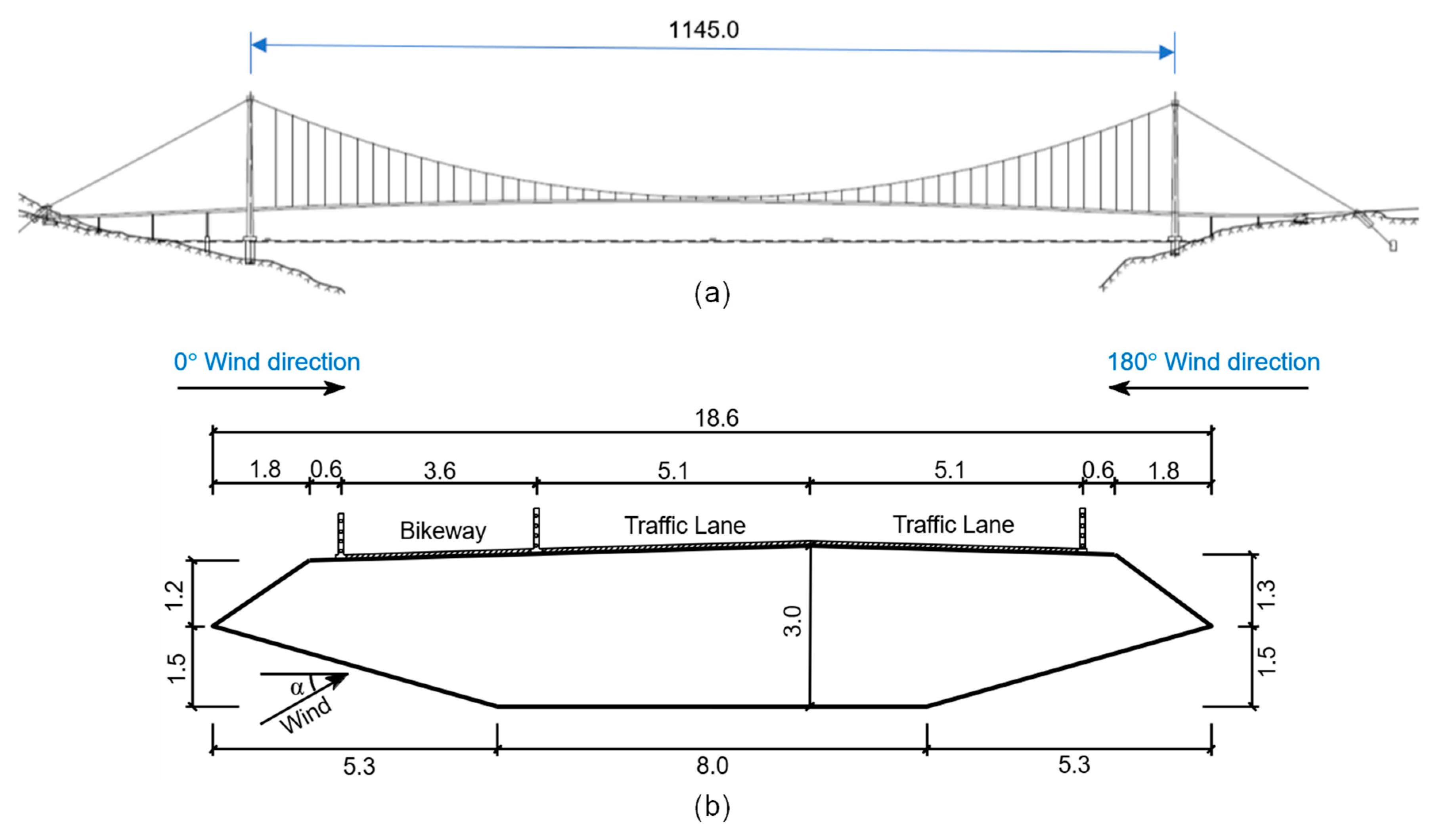
Figure 2 presents the general arrangement of the suspension bridge and the asymmetric box girder’s cross-section. As shown in Figure 2, the bridge has a main span of 1145.0 m. The width and height of the box girder are 18.6 m and 3.0 m, respectively. It is worth mentioning that a bikeway with a width of 3.6 m is set on one side of the bridge girder. The definitions of the WDA and the AOA are also illustrated in the figure, where the incoming flow in a WDA of 0° originates from the side of the asymmetric bikeway.

2.2. Test and Numerical Setup

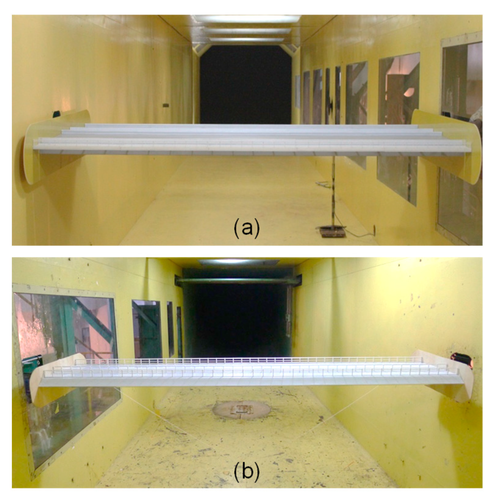
The XNJD-1 wind tunnel, equipped with a 2.4 m wide × 2.0 m high test section, was employed for the experiments. The section models of the asymmetric Π-shaped girder and the asymmetric box girder are displayed in Figure 3.
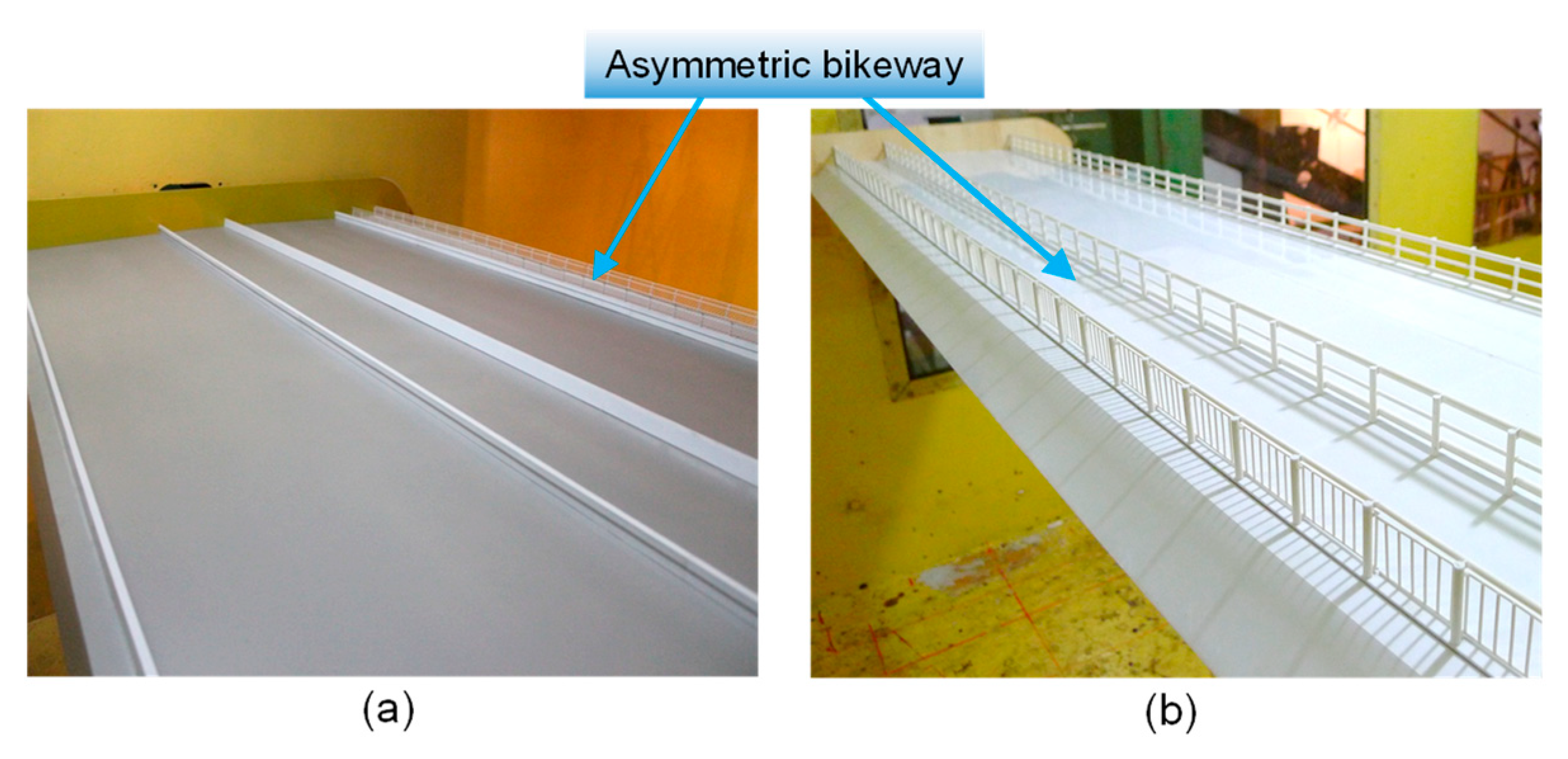
The asymmetric Π-shaped girder section model was designed at 1:45 scale, with model dimensions of L = 2.30 m, B = 1.171 m, and H = 0.071 m. The experimental model was fabricated using conventional stiff-model construction techniques. To enhance the model’s stiffness, the two steel box edge girders were constructed independently using aluminum beams. The girder surfaces and transverse beams were fabricated from glass-fiber-reinforced polymer (GFRP) sheets. The traffic barriers and other ancillary facilities were manufactured precisely from acrylonitrile butadiene styrene materials. The girder surface of the section models is shown in Figure 4. The box girder section model, scaled at 1:40, had dimensions of 2.10 m in length, 0.465 m in width, and 0.075 m in height. To ensure that the model has sufficient stiffness, the section model’s surface was made of glass fiber reinforced plastics, and the aluminum skeleton was installed inside the model. The wind fairings and traffic barriers were also manufactured from ABS materials. Two end plates were used to guarantee two-dimensional flow. For the two bridge girder section models, their blockage ratios are below 5%. Blockage effects can therefore be disregarded. It is also worth mentioning that all the tests in the present study were conducted in smooth flow fields. Although turbulent flow can result in changes to the aerodynamic forces and wind-induced responses of the bridge compared to the smooth flow condition, experimental results obtained under smooth flow conditions can still provide important references for wind-resistant bridge design. Specifically, in the actual wind-resistant design of bridges, the aerodynamic parameters used for predicting bridge buffeting and flutter responses, such as the static wind loading coefficients and flutter derivatives, are derived from smooth flow rather than turbulent flow conditions. Moreover, according to the Chinese wind-resistant design code [53], both VIV tests and flutter tests are required to be conducted in smooth flow fields to evaluate and optimize the VIV and flutter performance of bridge girders. Since results from smooth flow fields can provide references for wind-resistant bridge design, this paper does not investigate the results of turbulent flow fields. This study primarily focuses on the effects of WDA and AOA on the aerodynamic properties of asymmetric girders.

2.2.1. Static Wind Loading Test

The static wind loading tests employed a strain-gauge force balance to measure aerodynamic forces on the girder models. The force balance can measure the time history of lift, drag, and pitching moment simultaneously. The maximum load ranges are ±50 kg for the drag, ±120 kg for the lift, and ±12 kg·m for the pitching moment, respectively. The tests were carried out in smooth flow conditions. Data acquisition was performed at 1000 Hz for 30 s. The aerodynamic coefficients are defined as follows:
C D α = F D α / 0.5 ρ U 2 H L ,
C L α = F L α / 0.5 ρ U 2 B L ,
C M α = F M α / 0.5 ρ U 2 B 2 L ,
where α is the AOA, FD, FL, and FM represent drag, lift, and pitching moment per unit span, ρ denotes air density, and U is the mean wind velocity. H, B, and L correspond to model height, width, and length.
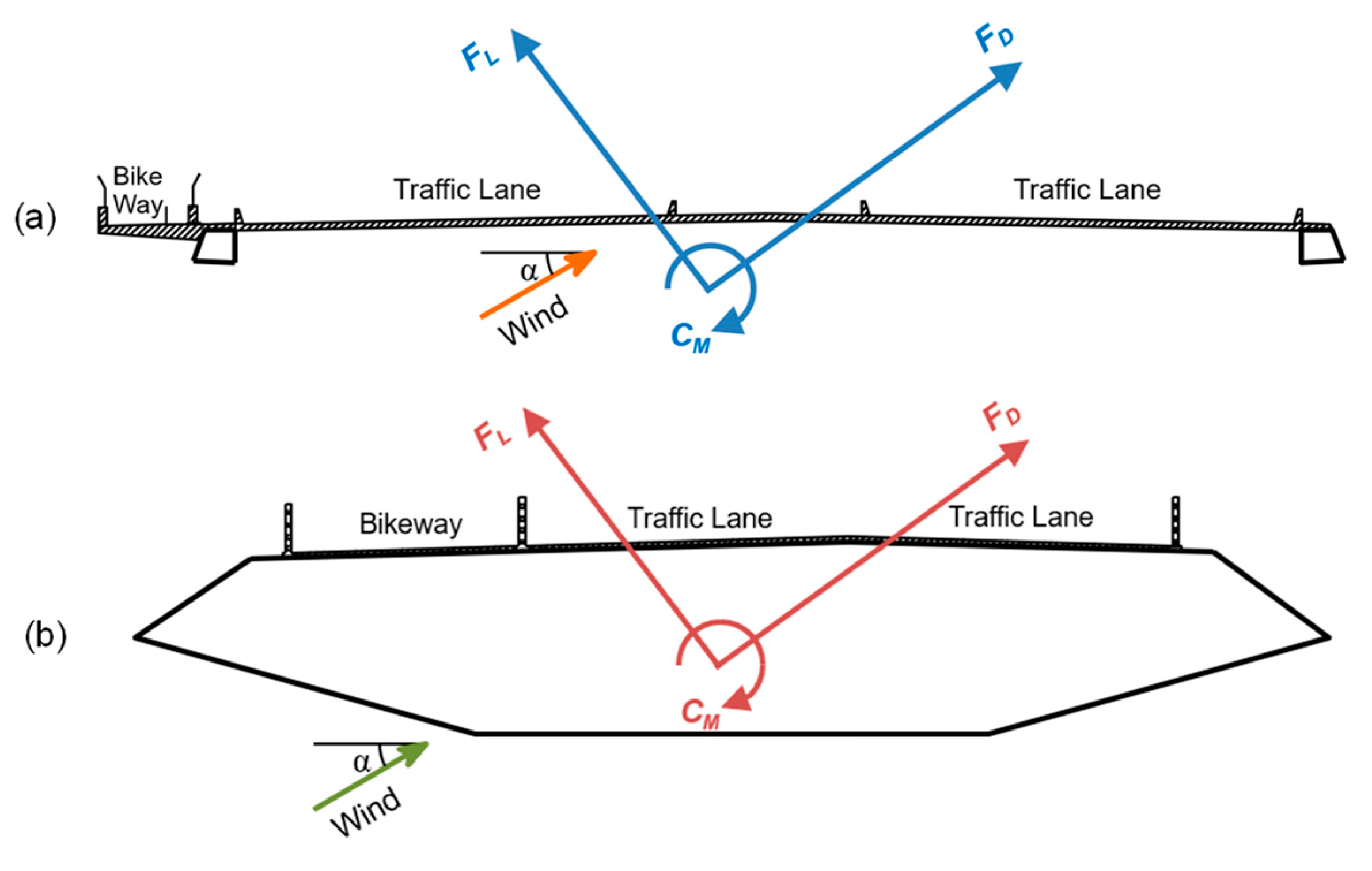
The sign conventions for aerodynamic forces on the two asymmetric girders are illustrated in Figure 5. To study the effects of asymmetric girder configurations on the static wind loading coefficients, the tests considered the wind coming from both sides of the girder. It is worth mentioning that the slope of the static wind loading coefficients with respect to the AOA is employed in the buffeting force model and serves as a crucial aerodynamic parameter for determining buffeting forces on bridge girders. Consequently, the investigated range of AOAs in this study spans from −10° to +10°. For the asymmetric Π-shaped girder, the static wind loading coefficients at AOAs ranging from −10° to 10° with a step of 2.5° were measured. For the asymmetric box girder, the static wind loading coefficients at AOAs ranging from −10° to 10° with a step of 1° were investigated. The tested mean wind velocity is 15.0 m/s. It should be noted that Reynolds number effects have significant influences on the aerodynamic forces and unsteady behaviors of slender bridge girders with sharp-edged cross-sections [54]. The conventional wind tunnel test results in the low Reynolds number region are conservative for the wind-resistant design of bridge decks [55]. In the prototype condition, the Reynolds number of a bridge girder is on the order of 107. However, achieving similarity in Reynolds numbers in conventional section model wind tunnel testing is impractical. In the present static wind loading tests, the Reynolds numbers (Re) of the main flow, based on the model thickness, are 6.13 × 10⁴ and 8.17 × 10⁴ for the asymmetric Π-shaped girder and asymmetric box girder, respectively.

2.2.2. Flutter Derivative Identification Test

The flutter derivative of the asymmetric Π-shaped girder and the asymmetric box girder were identified in smooth flow at a 0° AOA. Two WDAs of 0° and 180° were considered in the tests. Scanlan and Tomko’s [56] linearized self-excited aerodynamic force model remains the most widely used approach for critical flutter estimation. Chen and Kareem’s [57] and Matsumoto et al.’s alternative models [58] exhibit three primary variations while maintaining equivalent physical interpretations. The per-unit-length self-excited forces are formulated as follows:
L s e = ρ U 2 B k H 1 * h · U + k H 2 * B θ · U + k 2 H 3 * θ + k 2 H 4 * h B ,
M s e = ρ U 2 B 2 k A 1 * h · U + k A 2 * B θ · U + k 2 A 3 * θ   + k 2 A 4 * h B ,
where h and θ represent the heaving and torsional displacements, and h ˙ and θ ˙ are their derivatives with respect to time, k = fB/U represents reduced frequency, and H i * and A i * (i = 1~4) denote the flutter derivatives, which are functions of reduced frequency.
The flutter derivatives were identified using the free-vibration testing methodology. The schematic diagram of the procedure to identify the flutter derivatives of bridge girders is illustrated in Figure 6. It is noted that the weighting ensemble least-square method (WELS) proposed by Li et al. [59] was used to extract all eight flutter derivatives of the bridge girder from free vibration records. In this approach, multiple free-vibration time histories at identical wind velocities were aggregated into ensemble datasets for analysis. Common-mode parameters were simultaneously identified from the ensemble data through nonlinear least-squares estimation. Weighting factors were introduced to equalize the contribution of each test record based on total residual error analysis. This ensemble approach, incorporating multiple records, effectively reduced the influence of colored noise in the original data and improved the convergence of the iterative least-squares solution. Following determination of the precise modal parameters, all flutter derivatives were subsequently identified using a state-space method.
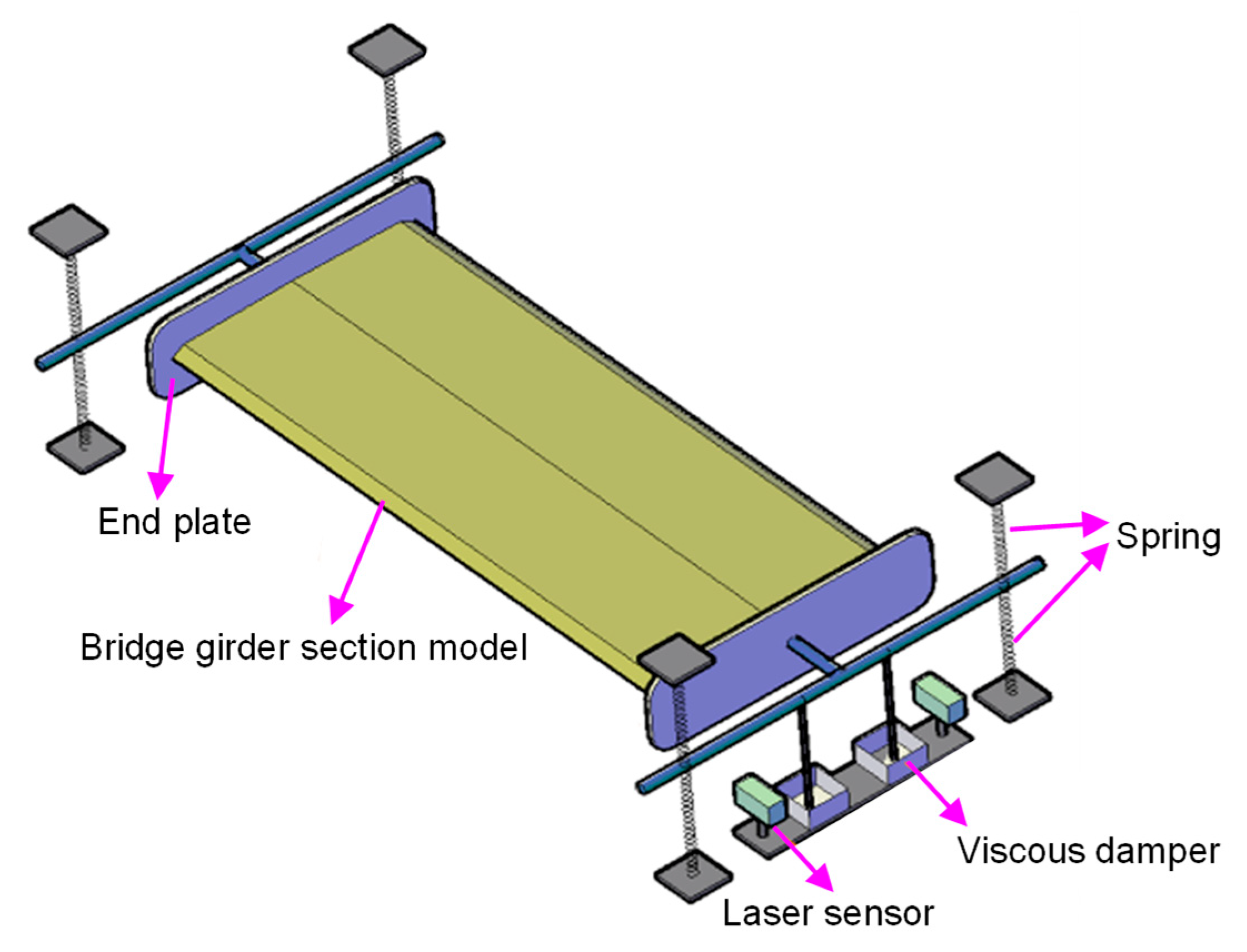
The dynamic tests utilized a specialized girder section setup (see Figure 7). Installed on the wind tunnel walls, the setup used four spring pairs to suspend the model for coupled heaving/torsional vibration studies. Both ends of the section model were fitted with end plates to simulate two-dimensional flow conditions. Viscous dampers were implemented to modulate and simulate the damping of the dynamic test system. The vibration time histories were measured by using laser sensors (type: ILD1401-200). Two laser sensors were used to monitor the model’s flow-induced vibration displacements. The CRAS 7.1 dynamic signal analysis system acquired data at a 512 Hz sampling rate during 64 s tests, enabling real-time signal processing. It should be noted that repeated flutter derivative identification tests were conducted, enabling error analysis of the flutter derivatives. The main parameters of the flutter derivative identification tests of the two types of bridge girders are listed in Table 1 and Table 2, respectively.

2.2.3. VIV Test

The VIV test was conducted to study the asymmetric Π-shaped girder’s VIV characteristics. The VIV responses of the asymmetric Π-shaped girder at AOAs of 0°, ±2.5°, and ±5° were investigated in smooth flow. Two WDAs of 0° and 180° were considered in the tests. The test setup and section model parameters matched those employed in the flutter derivative identification test. As mentioned before, the Reynolds number effects have significant influences on the VIV responses of the bridge. In the present VIV tests, the Reynolds numbers of the main flow, based on the model thickness of the asymmetric Π-shaped girder, range from 3.16 × 10³ to 3.69 × 10⁴.

2.2.4. Flutter Test

A comparative analysis of flutter behavior was conducted for the asymmetric Π-shaped and box girder designs, including quantification of critical flutter velocities in uniform flow. Two WDAs of 0° and 180° were considered in the tests. The AOAs of ±2.5° and 0° were covered for the asymmetric Π-shaped girder, and the AOAs of ±3° and 0° were covered for the asymmetric box girder, respectively. Repeated flutter tests were conducted to perform error analysis on the critical wind speeds of the two types of asymmetric bridge girders. The test setup for the two types of asymmetric bridge girders is the same as used in the flutter derivative identification and VIV tests. The parameters of the flutter test of the asymmetric Π-shaped girder are the same as those in the flutter derivative identification test, except for the damping ratios. The damping ratios of the flutter test are 0.873% and 0.864% for heaving and torsional modes, respectively. For the asymmetric box girder, the parameters of the flutter test are the same as those in the flutter derivative identification test, as listed in Table 2.

2.2.5. Numerical Setup

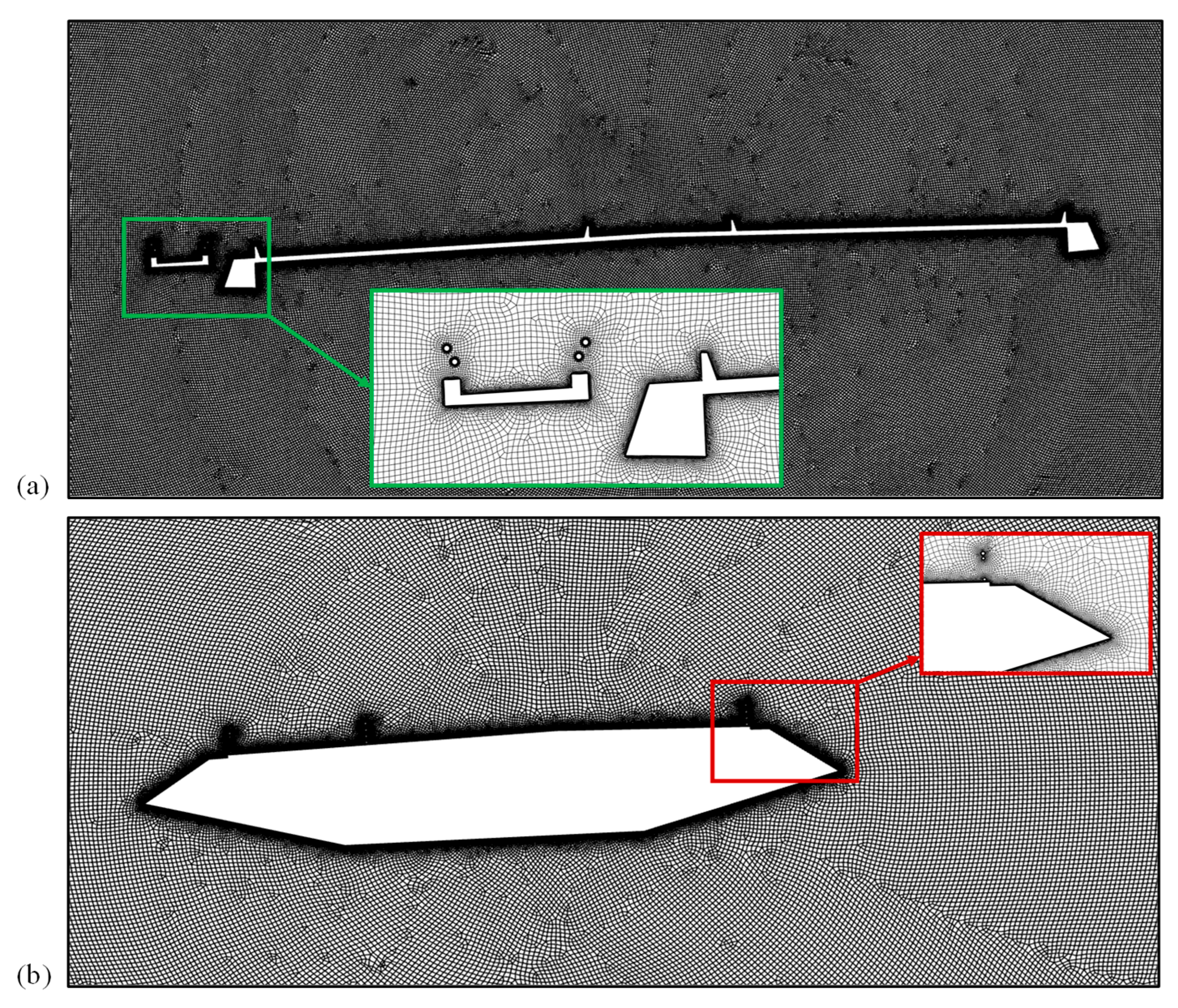
The 2D flow field was simulated numerically in smooth flow utilizing the SST k-ω turbulence model and the commercial software Fluent 2022R1. The computational domain was 90D1 × 200D1 and 38D2 × 76D2 for the Π-shaped girder and box girder, respectively, as illustrated in Figure 8, where D1 and D2 represent the Π-shaped girder and box girder height, respectively. The dimensions of the numerical model were consistent with those of the sectional model experiments. The SIMPLE pressure–velocity coupling algorithm was used to solve the discretized problem numerically. As shown in Figure 9, the multi-block meshing strategy, which could generate a high-quality mesh with minimal computational complexity, was employed in the present study. To maintain that the y+ value was less than 1, the multilayer mesh with boundary layers had ten layers with an initial height of 2.1 × 10⁻⁵ mm and a growth rate of 1.2. To enhance the precision and effectiveness of calculations, the grids surrounding the guardrails and bridge decks were locally densified. The grid size surrounding them was 2 × 10⁻⁴ mm, and the mesh size growth rate was 1.1. The total number of meshes is approximately 3.7 × 10⁵ and 2.0 × 10⁵ for the Π-shaped girder and the box girder, respectively.
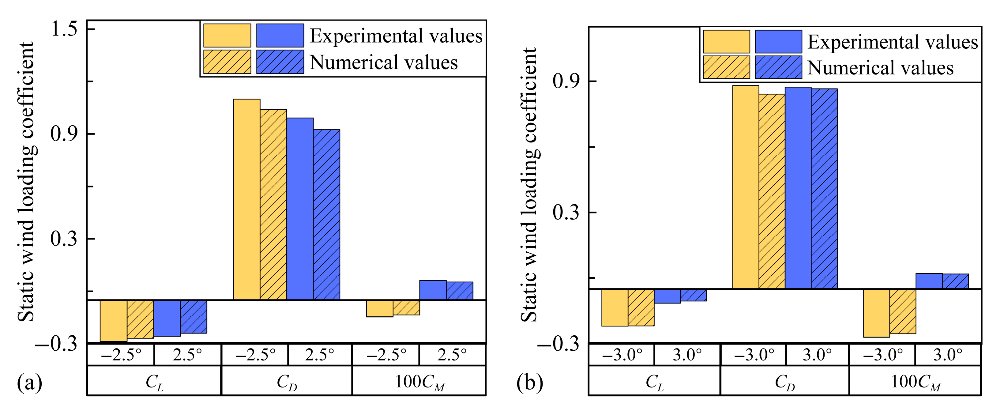
To validate the CFD results in this study, the numerical results of the drag, lift, and torsional moment coefficients (CD, CL, and CM) at a 0° WDA are compared with those of the wind tunnel tests. It should be noted that the static wind loading coefficients of the Π-shaped girder were measured under ±2.5° AOAs, while those of the box girder were under ±3° AOAs. It can be found from Figure 10 that the static wind loading coefficients obtained from the CFD simulations align well with the test results. Although the value of the CFD results is slightly larger, the maximum error between the numerical results and those from the wind tunnel test is less than 7%.

3. Results and Discussions

In this section, the static wind loading coefficients, flutter derivatives, VIV displacements, and critical flutter velocities of the asymmetric Π-shaped girder and the asymmetric box girder are presented. The effects of the asymmetric aerodynamic configurations on the aerodynamic characteristics for the two types of bridge girders were analyzed in detail.

3.1. Static Wind Loading Coefficient

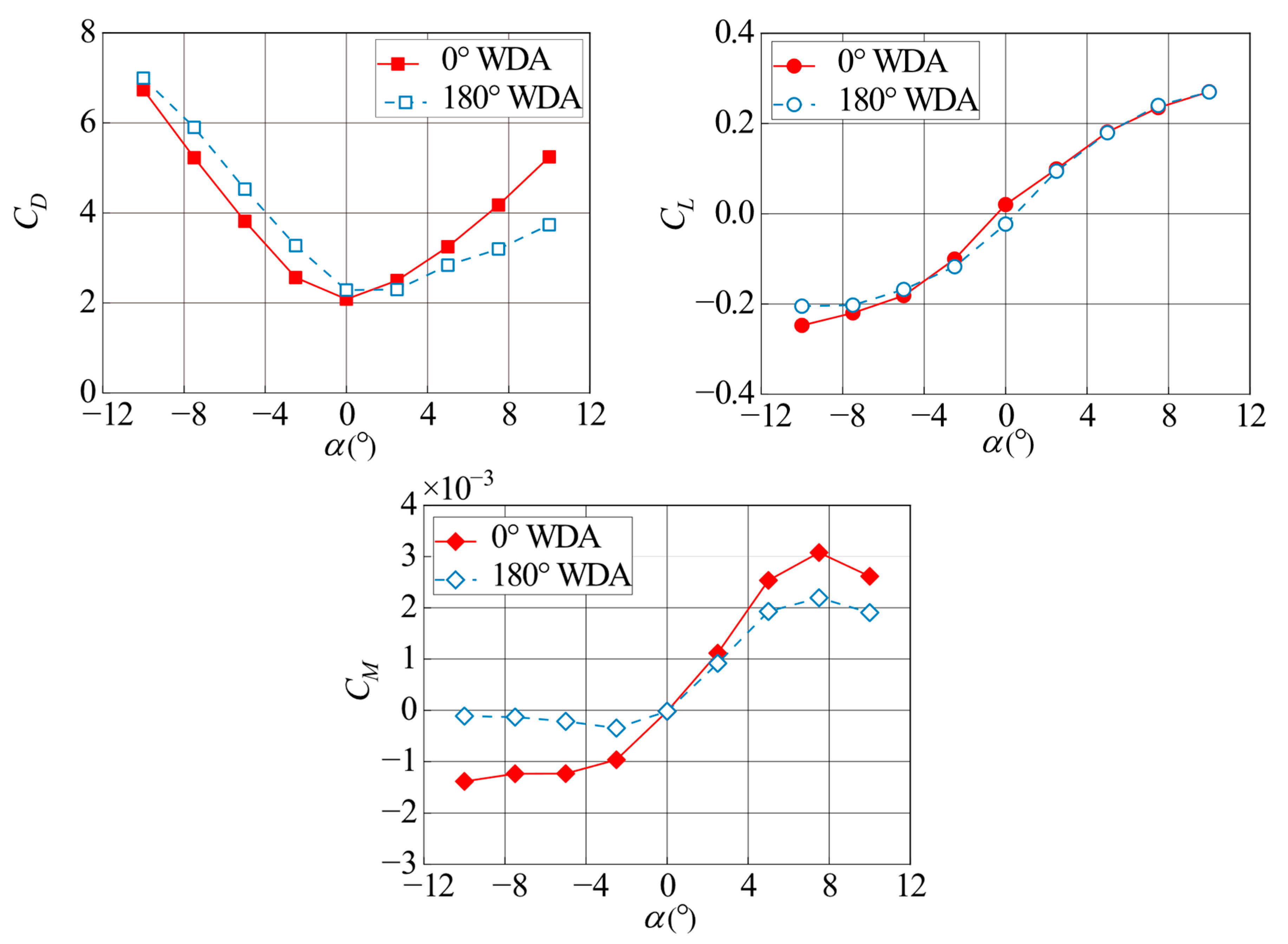
Figure 11 shows the curves of static wind loading coefficients of the asymmetric Π-shaped girder versus AOAs at 0° and 180° WDAs in smooth flow. The results show that the values of static drag coefficient CD at negative and zero AOAs at a 0° WDA are much smaller than those at a 180° WDA. When the attack angle increased to a positive value, the static drag coefficient’s slope versus the AOAs at a 0° WDA was much larger than that at a 180° WDA. Therefore, the value of CD increases rapidly as the AOAs increase, and it is significantly larger than that at a 180° WDA at large positive AOAs.
The result also shows that the values of the static lift coefficient CL of the asymmetric Π-shaped girder at 0° and 180° WDAs are very close at positive AOAs. The slope of CL versus the AOAs at a 0° WDA is larger than that at a 180° WDA at negative AOAs. Additionally, the values of CL at a 0° WDA are smaller than those at a 180° WDA at larger negative AOAs.
For the static pitching moment coefficient CM of the asymmetric Π-shaped girder, it is interesting to see that its variation trend versus the AOAs is very similar between 0° and 180° WDAs. The slopes of CM versus the AOAs are very small at negative AOAs for both 0° and 180° WDAs. The value of CM at a 0° WDA is significantly smaller than that at a 180° WDA at negative AOAs. The values of CM of 0° and 180° WDAs are very close at 0° AOAs. When the attack angle increases to a positive value, the slope of CM versus the AOAs at a 0° WDA is larger than that at a 180° WDA. This results in larger values of CM at 0° WDAs than those at 180° WDAs.
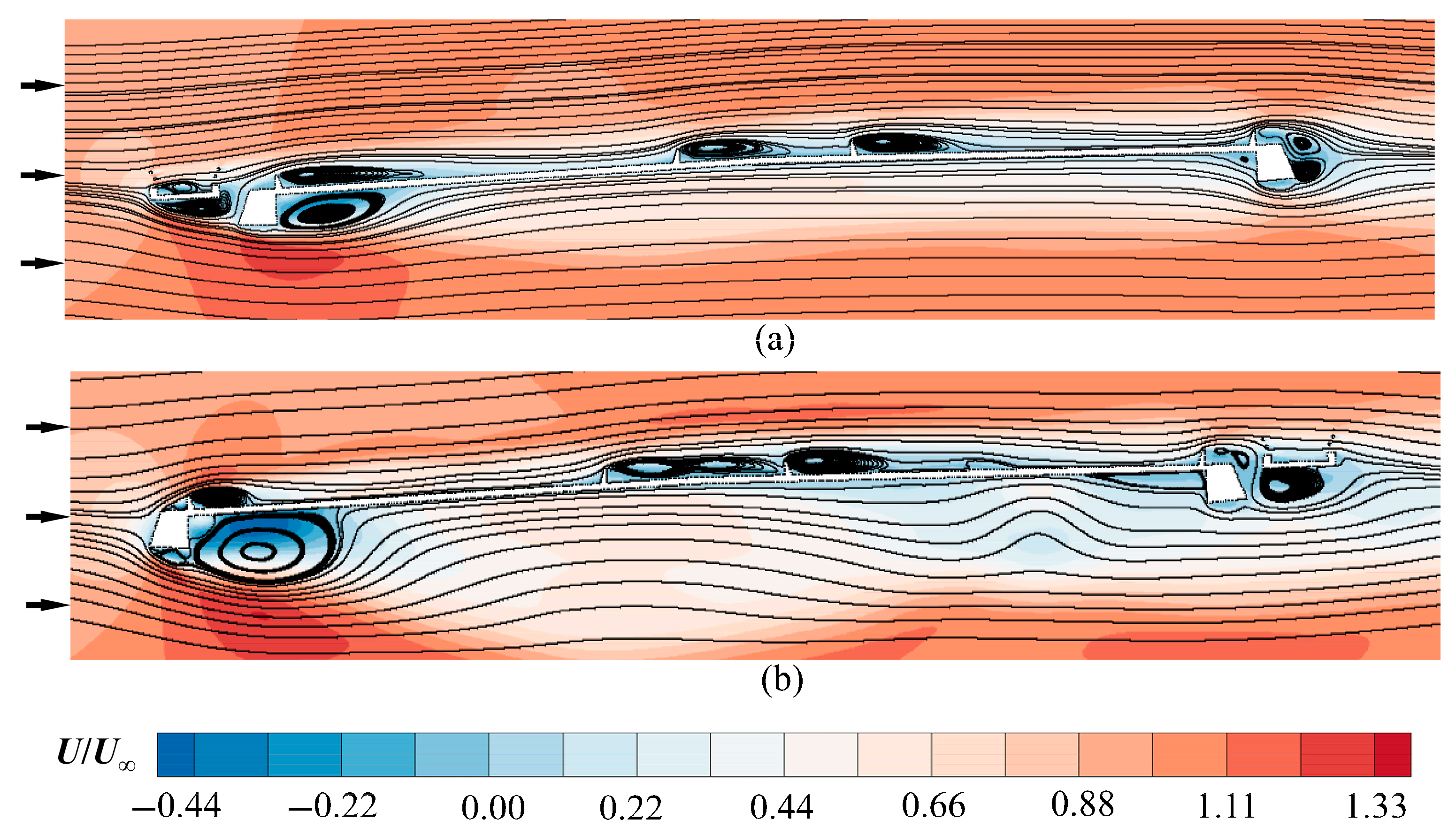
Figure 12 shows the mean velocity field and its streamlines for the asymmetric Π-shaped girder at a –2.5° AOA under the two WDAs. The flow patterns differ substantially between the 0° and 180° WDAs. With the bikeway on the windward side at 0° WDA, the approaching flow separates earlier, producing a markedly smaller vortex beneath the girder’s windward edge than at 180° WDA. This vortex induces pronounced negative pressure, which likely explains the lower lift coefficient observed at 180° WDA. In the wake, alternating vortices develop at 0° WDA, whereas only a single, coherent vortex forms beneath the bikeway at 180° WDA. These alternating vortices at 0° WDA generate a larger mean pitching moment than those at 180° WDA. This flow phenomenon may result in a greater amplitude of the mean pitching moment at 0° WDA, which is consistent with the results shown in Figure 11.
Figure 13 shows the curves of static wind loading coefficients of the asymmetric box girder versus AOAs at 0° and 180° WDAs in smooth flow. It can be found that the values of static drag coefficient CD are close between 0° and 180° WDAs when the AOA is in a range from −6° to 3°. The value of CD is smaller, and its slope versus the AOA decreases at 0° WDA at larger negative AOAs. However, the value of CD is larger, and its slope versus the AOA increases at 0° WDA at larger positive AOAs compared to the case of 180° WDA.
The results in Figure 13 also show that the variation trend of CL versus the AOA is very similar between 0° and 180° WDAs. When the AOA is smaller than −7°, the value of CL at a 0° WDA is smaller than that at a 180° WDA. As the AOA increases to −7°, the slope of CL versus the AOA at a 0° WDA becomes slightly larger than that at a 180° WDA, which results in larger values of CL.
For the static pitching moment coefficient CM of the asymmetric box girder, its variation with the AOA closely follows the static lift coefficient trend. The discrepancy in CM between 0° and 180° WDAs is slightly larger than CL when the AOA is larger than −7°.
The experimental results demonstrate that asymmetric girder configurations have an obvious effect on the static wind loading coefficients. Compared to the investigated asymmetric box girder, the discrepancy in CD and CM of the asymmetric Π-shaped girder between 0° and 180° WDAs is much larger. These results show that it is important to consider the influences of different WDAs on the static wind loading coefficients for the asymmetric girder sections, especially in cases of large AOAs.

3.2. Flutter Derivative

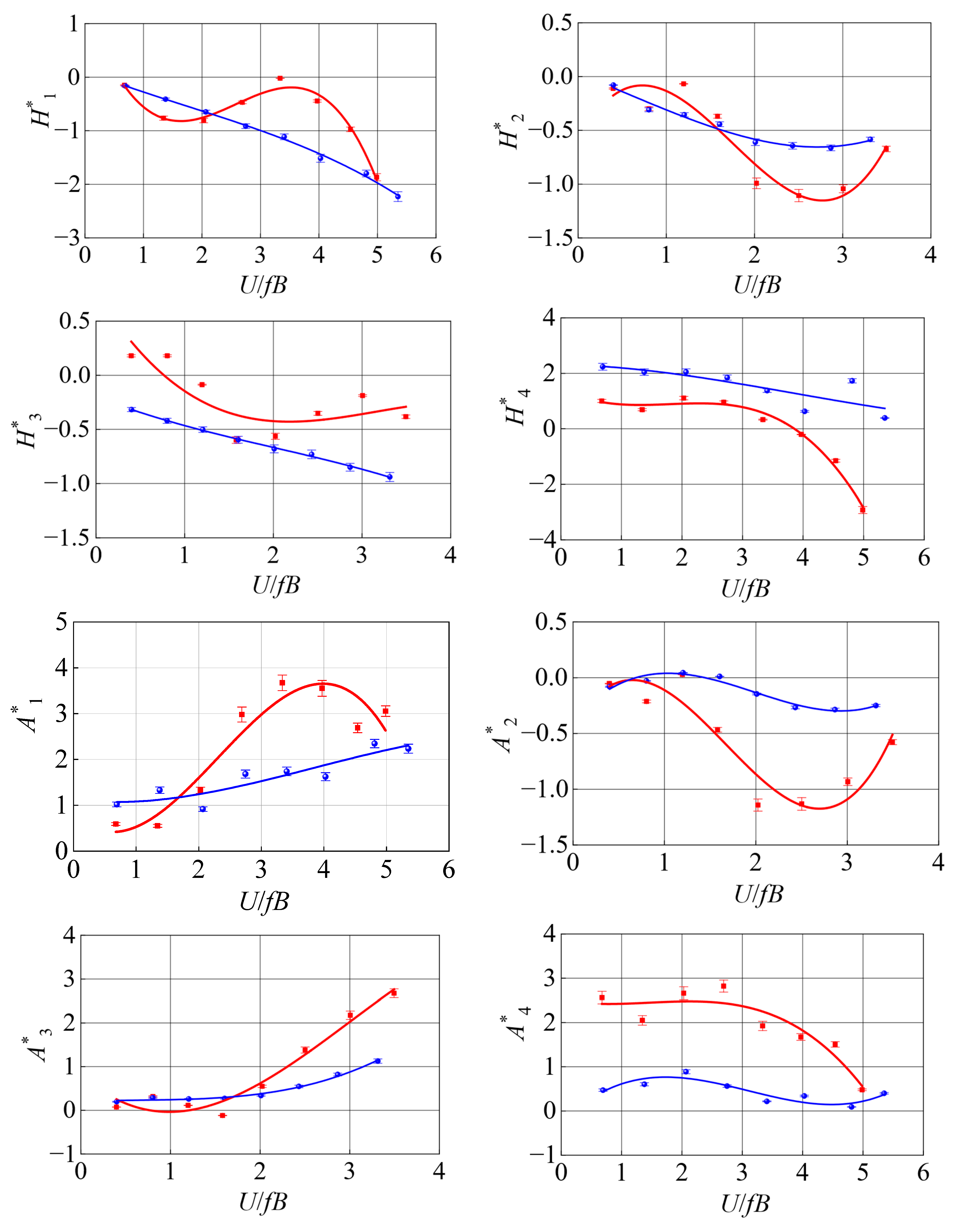
Figure 14 shows the comparison results of the flutter derivatives at a 0° AOA between 0° and 180° WDAs for the asymmetric Π-shaped girder. It is noted that in the figures, the symbol denotes the experimental identification results, and the solid line denotes the fitted results. Error bars for the flutter derivatives are also presented in the figure. The results show that the identification tests yield highly stable flutter derivatives, thereby confirming the reliability of the experimental apparatus in quantifying these parameters of the asymmetric Π-shaped girder. It can be seen that the influences of WDA on the flutter derivatives are obvious for the asymmetric Π-shaped girder. Compared to a WDA of 180°, the asymmetric Π-shaped girder’s flutter derivatives at a WDA of 0° exhibit greater changes with increasing reduced wind velocity. Additionally, the variation trends of H 1 * , H 2 * , A 1 * , A 2 * , A 4 * flutter derivatives differ between the two WDAs. For the flutter derivatives of H 3 * , H 4 * , and A 3 * , although quantitative differences are observed, their developmental patterns do not exhibit distinct changes with variations in reduced wind velocity. For the flutter derivative of H 1 * , it decreases almost linearly with increasing reduced frequency at a WDA of 180°. In contrast, at a WDA of 0°, H 1 * first decreases, then increases, reaches a peak, and subsequently decreases rapidly with increasing reduced wind velocity. For the aerodynamic damping derivative A 2 * related to the self-excited pitching moment, its value at a WDA of 0° is significantly lower than that at 180° under higher reduced wind velocities. This result indicates that the main girder configuration provides enhanced aerodynamic torsional damping during flutter, thereby improving the flutter critical wind velocity.
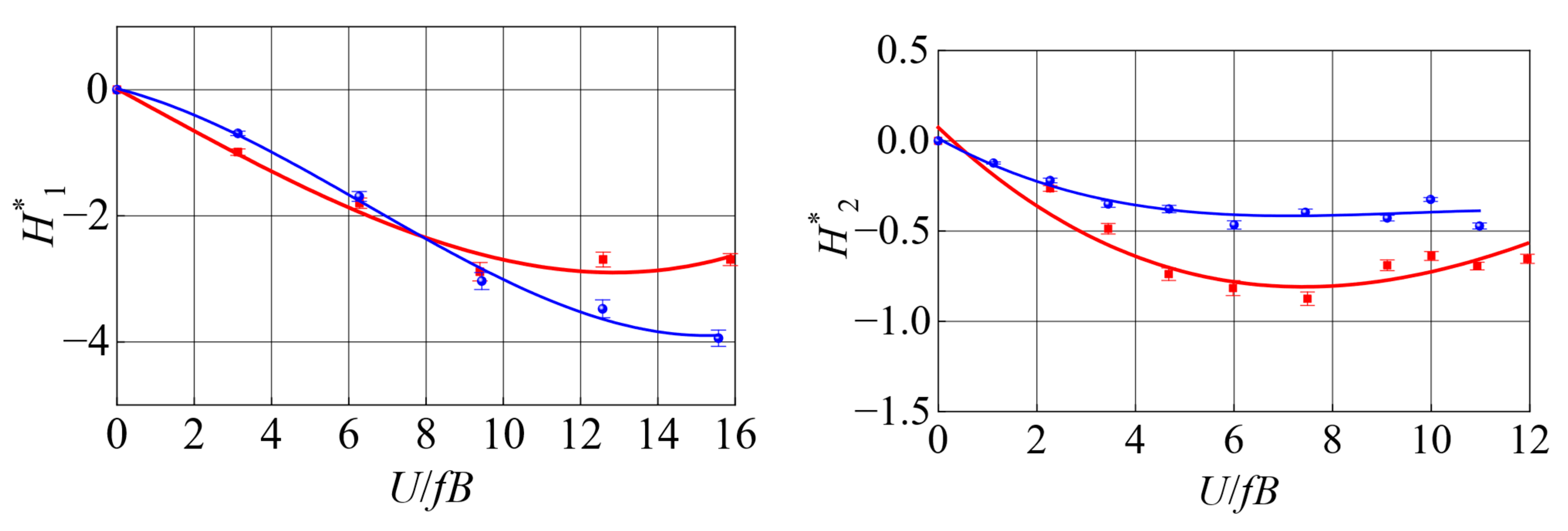
Figure 15 compares the 0° AOA flutter derivatives between 0° and 180° WDAs for the asymmetric box girder. Consistent with the legend specified in Figure 14, the symbol denotes the experimental identification results, and the solid line denotes the fitted results. The error bars in the figure demonstrate that the identified flutter derivatives of the asymmetric box girder are highly stable. It can be found from Figure 15 that, except for the flutter derivative of H 4 * , the other flutter derivatives’ variation trends with increasing reduced wind velocity are the same for 0° and 180° WDAs. For the flutter derivatives of H 3 * and A 3 * , their values exhibit very little difference between WDAs of 0° and 180°. For the flutter derivatives of H 2 * and H 4 * , their variation trend is similar to the increasing reduced wind velocity. Their values at a 0° WDA are smaller than those at a 180° WDA. For the flutter derivatives of A 1 * and A 4 * , they all increase with the increase in reduced wind velocity, and the values at a 0° WDA are greater than those at a 180° WDA. For both 0° and 180° WDAs, the H 1 * derivative demonstrates consistent negative values that diminish progressively with rising reduced wind velocity. This indicates that for this asymmetric box girder, aerodynamic damping can be provided for the bridge girder’s heaving bending motion at high reduced wind velocities. Comparing the results for the two WDAs reveals that the values of H 1 * remain comparable between 0° and 180° WDAs at reduced wind velocities below 10. However, as the reduced wind velocity further increases, the value at a 0° WDA becomes greater than that at a 180° WDA. For the flutter derivative of A 2 * , the value at a 180° WDA decreases almost linearly with increasing reduced wind velocity and remains negative. However, when the incoming WDA is 0°, the value of A 2 * decreases slowly at U/fB below 6 and then decreases rapidly when U/fB exceeds 6. The difference between its value and that at a 180° WDA increases progressively.
Comparisons of the results in Figure 14 and Figure 15 reveal that the impact of WDAs on the asymmetric Π-shaped girder’s flutter derivatives is more pronounced than that on the asymmetric box girder. Compared to the asymmetric box girder, the asymmetric bikeway of the Π-shaped girder exerts a more pronounced influence on the differences in flutter derivatives across WDAs. This is primarily because the bikeway, positioned away from the main Π-shaped girder, triggers an early flow separation, giving rise to markedly different flow structures around the girder between 0° and 180° WDAs. Additionally, the results indicate that the torsional aerodynamic damping derivative A 2 * exhibits a lower magnitude at a 0° WDA than at the corresponding 180° WDA, especially at high reduced wind velocities. This suggests that 0° WDA from the side of the asymmetric bikeway can provide more torsional aerodynamic damping for both types of asymmetric girders, which is beneficial for enhancing the flutter stability of the girders under this WDA. It is inferred that the smaller A 2 * values at a 0° WDA are attributable to the suppression of flow separation around the girder surface. For the asymmetric Π-shaped girder, with the bikeway situated at the windward edge at a 0° WDA, separation initiates earlier than at a 180° WDA, thereby weakening the separation near the deck’s windward edge. For the asymmetric box girder, it is inferred that the bikeway railing on the leeward side induces premature separation and earlier reattachment on the upper deck surface at a 0° WDA, thereby weakening the separation at the leeward corner and reducing the wake vortex intensity relative to the 180° WDA case.

3.3. VIV Response

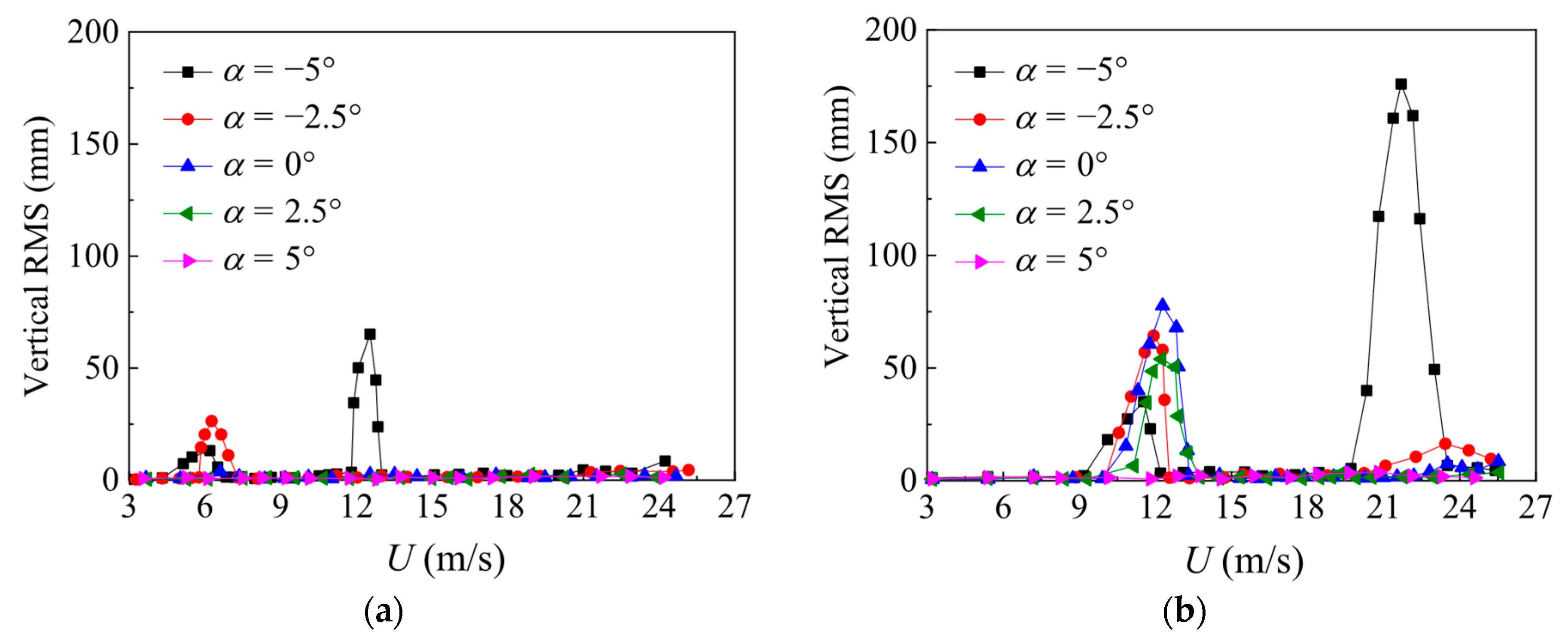
Figure 16 shows the root mean square (RMS) heaving displacement response of the asymmetric Π-shaped girder at different AOAs and WDAs. It can be found that the characteristics of heaving VIVs are different between 0° and 180° WDAs. First, the occurrence of AOAs of heaving VIVs is different between 0° and 180° WDAs. The heaving VIVs only occur at −2.5° and −5° AOAs at 0° WDA. However, the heaving VIVs occur at all investigated AOAs of ±5°, ±2.5°, and 0° at 180° WDA. Second, the peak RMS amplitudes of heaving VIV responses at −5° and −2.5° AOAs at a 180° WDA are significantly larger than those of −5° and −2.5° AOAs at a 0° WDA. Third, the lock-in region of the heaving VIVs is different between 0° and 180° WDAs. The lock-in wind velocity range for heaving VIV at a 180° WDA is much wider than that at a 0° WDA, especially in the second heaving VIV lock-in range of a −5° AOA.
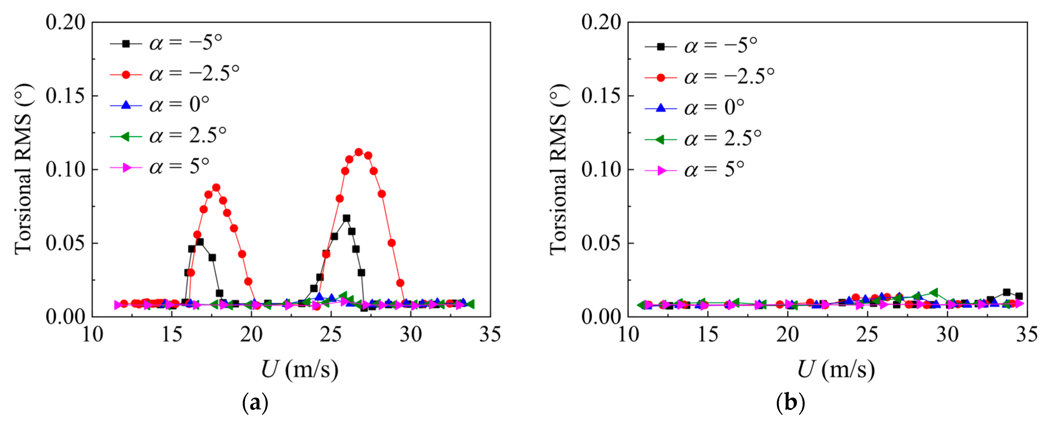
Figure 17 presents the root mean square (RMS) torsional displacement response of the asymmetric Π-shaped girder at different AOAs and WDAs. It can be found that the torsional VIV occurs at −5° and −2.5° AOAs at a 0° WDA. However, torsional VIV did not occur at the five investigated AOAs at a 180° WDA. At a 0° WDA, there are two torsional lock-in ranges for both −5° and −2.5° AOAs. Compared with the heaving VIV responses, the wind velocity range of torsional VIV is much wider, in particular for the −2.5° AOA.
From the above analysis of the heaving and torsional VIVs, the asymmetric Π-shaped girder exhibits more favorable heaving VIV characteristics at the 0° WDA relative to the 180° WDA. However, the asymmetric Π-shaped girder’s torsional VIV characteristics at a 180° WDA are better than those at a 0° WDA. It is inferred that the existence of the asymmetric bikeway on the girder causes early separation of flow at a 0° WDA compared to that at a 180° WDA. This phenomenon results in the different heaving and torsional VIV characteristics between 0° and 180° WDAs.
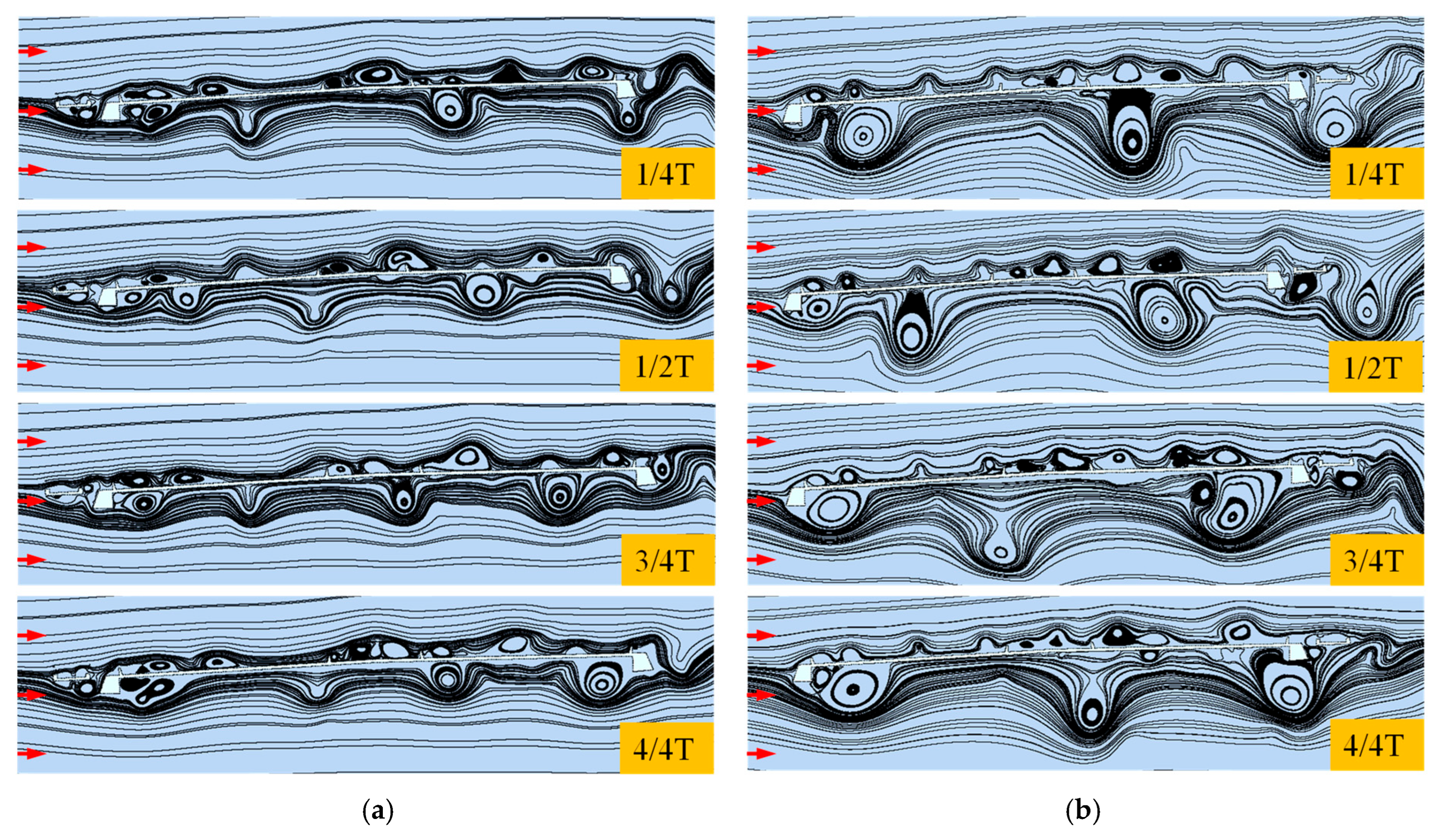
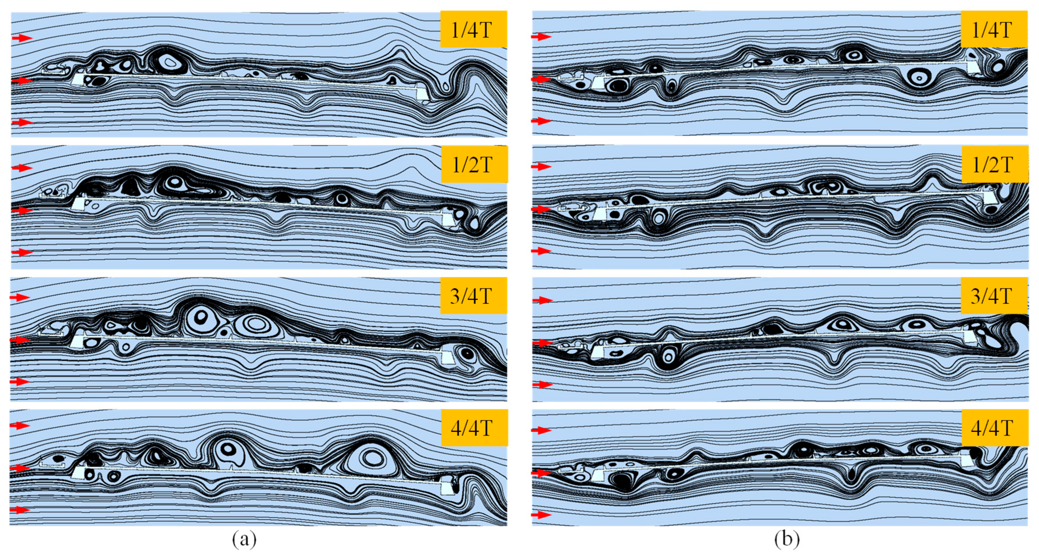
Figure 18 presents the instantaneous streamlines around the asymmetric Π-shaped girder under a −2.5° AOA in different WDAs. The results show that a cluster of large-scale vortices beneath the girder at a 180° WDA. These vortices generate intense suction, producing large fluctuating lift forces that amplify the heaving VIV responses relative to 0° WDA. This flow phenomenon may be responsible for the reason why the heaving VIV responses of the Π-shaped girder are triggered over a wider range of AOAs at a 180° WDA than at a 0° WDA, exhibiting larger RMS heaving displacements and broader lock-in regions. Additionally, more vortices form close to the deck’s upper surface, especially on the leeward side, where a stronger alternating vortex street develops at a 0° WDA. This likely produces a larger torsional vortex-induced force, making the torsional vortex-induced response more pronounced than at a 180° WDA.

3.4. Critical Flutter Velocity

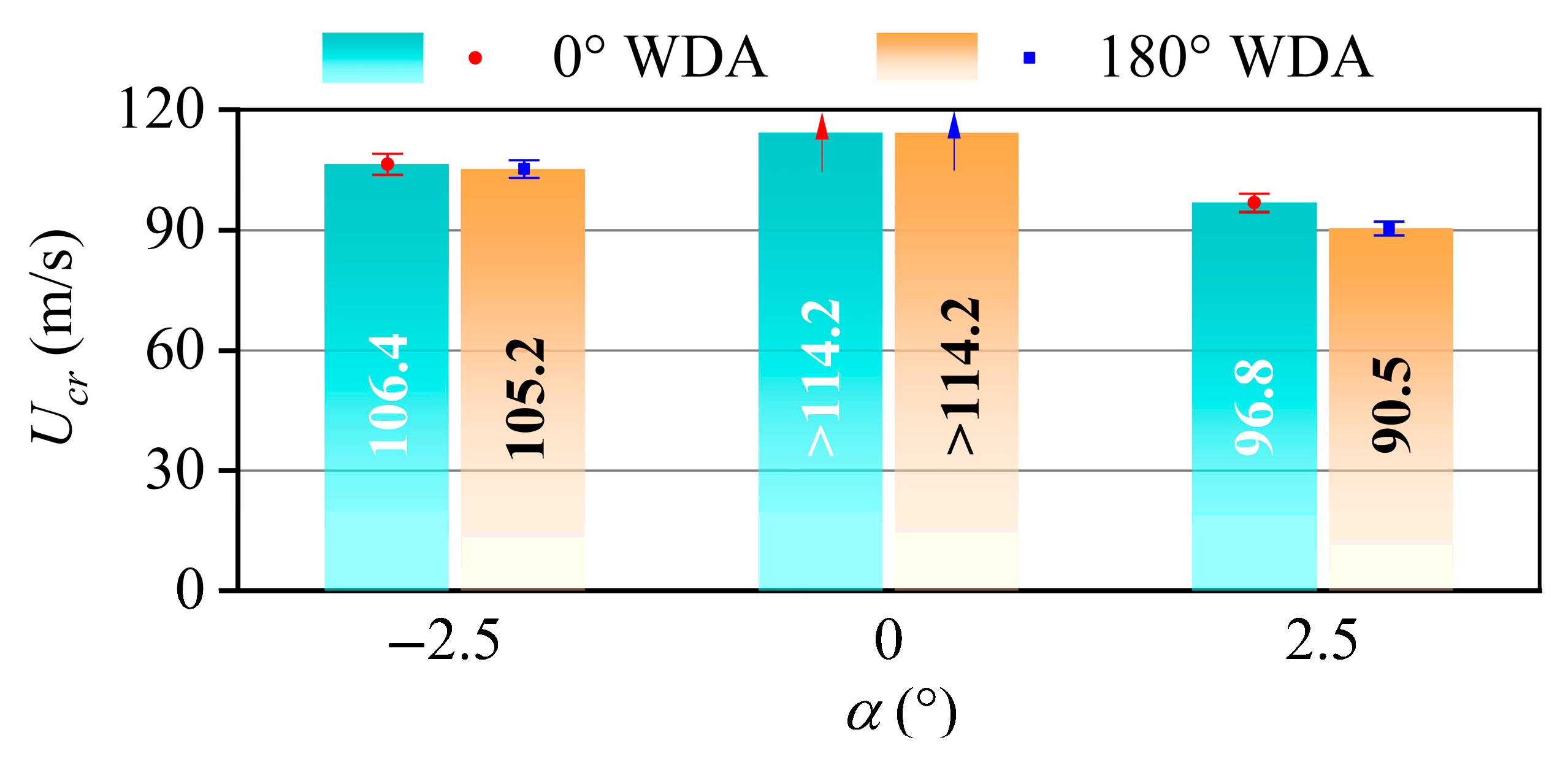
Figure 19 shows the asymmetric Π-shaped girder’s critical flutter velocity at different AOAs at 0° and 180° WDAs. The error bars in the figure demonstrate that the measured critical flutter velocities exhibit good stability. It can be found that the AOA of 2.5° constitutes the most adverse condition for asymmetric Π-shaped girder flutter performance. Additionally, comparative analysis reveals enhanced flutter resistance for the Π-shaped girder configuration under 0° WDA relative to 180° WDA, especially at a positive AOA of 2.5°. When the AOA is 2.5°, the critical flutter velocity at a 0° WDA is 7.0% higher than that at a 180° WDA.
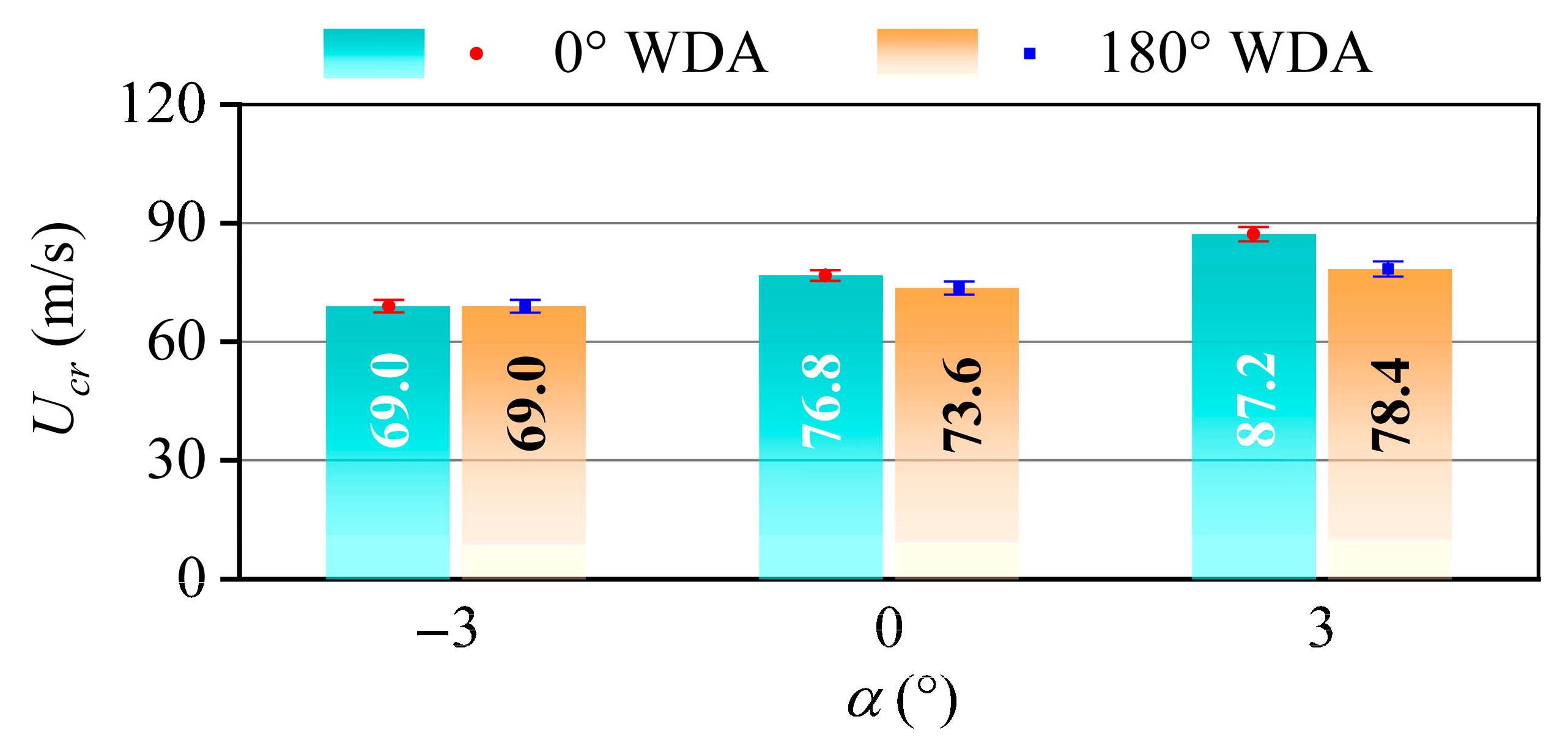
Figure 20 shows the critical flutter velocity of the asymmetric box girder at different AOAs at 0° and 180° WDAs. Analysis reveals the −3° AOA represents the most critical condition for flutter instability in the asymmetric box girder configuration. Figure 20 also shows that the flutter resistance of the box girder at a 0° WDA is better than that at a 180° WDA, especially at a positive AOA of 3°. This result is similar to that of the asymmetric Π-shaped girder. At 3° AOA, the critical flutter velocity under 0° WDA exceeds the 180° WDA value by 11.2%.
The comparative analysis of critical flutter velocities for both asymmetric girder configurations reveals significant performance variations across different WDAs. The critical flutter velocity at a 0° WDA is obviously higher than that at a 180° WDA, especially at positive AOAs. For the asymmetric Π-shaped girder, because the bikeway is located at the windward edge of the bridge girder at a 0° WDA, it acts similarly to a horizontal plate, improving bridge girder flutter performance, especially at a 2.5° AOA. At 2.5° AOA, the critical flutter velocity of the bridge girder at a 0° WDA is 6.2% higher than that at a 180° WDA. For the asymmetric box girder, at 3° AOA, the critical flutter velocity of the bridge girder at a 0° WDA is 10.1% higher than that at a 180° WDA for the asymmetric box girder. Chen et al. [60] demonstrated that upper stabilizers reduce aerodynamic damping while elevating critical flutter velocities in bridge girders. Because the railing on the bikeway is near the windward edge of the girder at a 0° WDA, it plays the role of an upper stabilizer to some extent. This effect on the increase in flutter stability becomes pronounced when the AOA is positive. The asymmetric box girder, therefore, has a better flutter performance at a 0° WDA compared to the 180° WDA.
To explain the differing critical flutter wind speeds at different AOAs, the instantaneous streamlines around the asymmetric girders at a 0° WDA under positive and negative AOAs are compared. The numerical results of the asymmetric Π-shaped and box girders are presented in Figure 21 and Figure 22, respectively. Figure 21 shows that the vortex scale above the upper surface of the Π-shaped girder is larger at a +2.5° AOA than at a –2.5° AOA. Specifically, these large vortices are located near the leeward edge of the girder, which may generate substantial torsional self-excited forces and thus reduce the critical flutter wind speed at a 2.5° AOA. For the asymmetric box girder, Figure 22 shows that larger-scale vortices form beneath the lower inclined web plate on the leeward side at a –3° AOA than at a 3° AOA. These vortices develop into pronounced vortex streets in the wake, leading to stronger torsional excitation. Consequently, the critical flutter wind speed is higher at a 3° AOA compared to a –3° AOA.

4. Conclusions

Taking two long-span bridges with asymmetric Π-shaped girders and box girders as examples, the aerodynamic performance, including the static wind loading coefficient, flutter derivative, VIV response, and the critical flutter velocity in different WDAs, was studied. This study’s main conclusions are as follows:
(1)
The asymmetric girder configurations have an obvious effect on the static wind loading coefficients for the two types of bridge girders. The mean flow structures and patterns differ markedly between 0° and 180° WDAs, leading to large discrepancies in the static wind loading coefficients at the specified AOA.
(2)
The effect of WDA on the flutter derivatives of the asymmetric Π-shaped girder is more pronounced than that on the asymmetric box girder. The flutter derivative of A 2 * of the two types of asymmetric bridge girders is much smaller in a WDA of 0° than that at a 180° WDA at high reduced wind velocities. This implies that the 0° WDA from the side of the asymmetric bikeway can provide more torsional aerodynamic damping, which is beneficial for enhancing the flutter stability of the bridge.
(3)
For the asymmetric Π-shaped girder, the heaving VIV responses at a 0° WDA are smaller than those at a 180° WDA. A cluster of large-scale vortices beneath the girder at a 180° WDA. These vortices generate intense suction, producing large fluctuating lift forces that amplify the heaving VIV responses relative to a 0° WDA. However, the torsional VIV responses at a 0° WDA are larger than those at a 180° WDA. Additional vortices cluster near the upper deck, especially on the leeward side, where a more intense alternating vortex street forms. This enhanced wake excitation generates larger torsional forces, thereby amplifying the torsional VIV response.
(4)
The flutter performances of two kinds of asymmetric bridge girders are very different between different WDAs. The critical flutter velocity at a 0° WDA is higher than that at a 180° WDA, especially at positive AOAs. It is inferred that for the asymmetric Π-shaped girder, the windward bikeway acts similarly to a horizontal plate, improving bridge girder flutter performance. For the asymmetric box girder, the railing assembly along the windward bikeway serves as a vertical stabilizer, resulting in enhanced critical flutter wind velocities.
This study demonstrates the necessity of accounting for the influences of WDA for the bridge girder with asymmetric aerodynamic configurations. Careful consideration must be given to aerodynamic coefficient selection across varying WDAs when conducting wind vibration response theoretical predictions. Moreover, to accurately assess the flutter and VIV characteristics of bridges, the influence of WDA must be considered. This ensures a rational and comprehensive evaluation of the bridges’ wind-resistant performance.

Author Contributions

Conceptualization, X.C. and H.Y. (Helu Yu); methodology, X.C. and H.Y. (Helu Yu); validation, H.Y. (Haowei Yu) and P.Z.; formal analysis, H.Y. (Haowei Yu) and M.L.; investigation, P.Z.; writing—original draft preparation, X.C.; writing—review and editing, H.Y. (Helu Yu) and M.L.; supervision, H.Y. (Helu Yu); funding acquisition, X.C. and H.Y. (Helu Yu). All authors have read and agreed to the published version of the manuscript.

Funding

This research was funded by the Young Elite Scientist Sponsorship Program by CAST (Grant No. YESS20240893), the Sichuan Science and Technology Program (Grant No. 2023ZDZX0008), the Science and Technology R&D Project of CREC (Grant No. 2025-Major-10), the Corporate-Level R&D Project of CREEC (Grant No. KSNQ233017), and the Special Postdoctoral Research Funding Project of Chongqing (Grant No. 2023CQBSHTB3100).

Institutional Review Board Statement

Not applicable.

Informed Consent Statement

Not applicable.

Data Availability Statement

The original contributions presented in this study are included in the article. Further inquiries can be directed to the corresponding author.

Acknowledgments

The authors thank the reviewers for their great help with the article during its review progress.

Conflicts of Interest

Authors Xingyu Chen and Pinyi Zhao were employed by the company Postdoctoral Workstation, CREEC (Chongqing) Survey, Design and Research Co., Ltd. Authors Xingyu Chen and Haowei Yu were employed by the company Institute of Science and Technology, China Railway Eryuan Engineering Group Co., Ltd. The remaining authors declare that the research was conducted in the absence of any commercial or financial relationships that could be construed as a potential conflict of interest.

References

  1. Zhao, L.; Cui, W.; Shen, X.; Xu, S.; Ding, Y.; Ge, Y. A fast on-site measure-analyze-suppress response to control vortex-induced-vibration of a long-span bridge. Structures 2022, 35, 192–201. [Google Scholar] [CrossRef]
  2. Yang, F.; Zhang, X.; Xie, Z.; Hao, J. Wind performance of new and existing continuous beam bridges during construction stages. Buildings 2025, 15, 791. [Google Scholar] [CrossRef]
  3. Yang, Y.; Li, L.; Yao, G.; Wu, B.; Wang, D.; Yu, H.; Qu, H. Study on the influence of wind fairing parameters on the aerodynamic performance of long-span double-deck steel truss suspension bridge. Buildings 2024, 14, 2255. [Google Scholar] [CrossRef]
  4. Li, S.; Wang, P.; Wu, Y.; Zou, Y.; Yang, Q.; Tian, J.; Zhou, Y. Experiment study on vortex-induced vibration of variable cross-section bridge tower considering alongwind and acrosswind coupling effect. Eng. Struct. 2025, 327, 119678. [Google Scholar] [CrossRef]
  5. Li, M.; Li, M.; Yang, Y.; Li, S. On the refined buffeting analysis of long-span bridges: Which is the proper aerodynamic admittance? Adv. Wind Eng. 2025, 2, 100025. [Google Scholar] [CrossRef]
  6. Li, M.; Li, M.; Zhong, Y.; Luo, N. Buffeting response evaluation of long-span bridges with emphasis on the three-dimensional effects of gusty winds. J. Sound Vib. 2019, 439, 156–172. [Google Scholar] [CrossRef]
  7. Li, M.; Li, M.; Sun, Y. Effects of turbulence integral scale on the buffeting response of a long-span suspension bridge. J. Sound Vib. 2021, 490, 115721. [Google Scholar] [CrossRef]
  8. Su, Y.; Li, M.; Di, J.; Sun, R.; Li, M.; Qin, F.; Jiang, Y.; Wang, J. Scale effects on buffeting response of long-span bridges. Eng. Struct. 2025, 341, 120862. [Google Scholar] [CrossRef]
  9. Li, C.; Zou, M.; Li, K.; Han, Y.; Yan, H.; Cai, C. A study on post-flutter characteristics of a large-span double-deck steel truss main girder suspension bridge. Buildings 2024, 14, 3206. [Google Scholar] [CrossRef]
  10. Russo, S.; Piana, G.; Patruno, L.; Carpinteri, A. Preliminary flutter stability assessment of the double-deck George Washington bridge. Appl. Sci. 2023, 13, 6389. [Google Scholar] [CrossRef]
  11. Wu, B.; Li, M.; Wu, L.; Shen, H.; Liao, H.; Mei, H. Study on aerodynamic forces and aeroelasticity of an oscillating 5: 1 rectangular cylinder in smooth and turbulent flow. J. Fluids Struct. 2025, 137, 104371. [Google Scholar] [CrossRef]
  12. Zhang, T.; Cui, X.; Zhang, X.; Li, H.; Zou, Y. Flutter reliability analysis of Xiangshan harbor highway cable-stayed bridges in service. Appl. Sci. 2022, 12, 8301. [Google Scholar] [CrossRef]
  13. Li, M.; Li, M.; Su, Y. Experimental determination of the two-dimensional aerodynamic admittance of typical bridge decks. J. Wind Eng. Ind. Aerodyn. 2019, 193, 103975. [Google Scholar] [CrossRef]
  14. Sun, Y.; Li, M.; Li, M.; Liao, H. Spanwise correlation of vortex-induced forces on typical bluff bodies. J. Wind Eng. Ind. Aerodyn. 2019, 189, 186–197. [Google Scholar] [CrossRef]
  15. Qin, C.; Li, M.; Li, M. Research on the vortex-induced vibration and aerodynamic mitigation measures of parallel Π-shaped girders under aerodynamic interference effects. Structures 2025, 71, 107996. [Google Scholar] [CrossRef]
  16. Jian, B.; Li, M.; Li, M.; Su, Y. Influence of wind yaw angle and pylon interference on the buffeting responses of cable-stayed bridges during construction. Struct. Infrastruct. Eng. 2022, 18, 1350–1364. [Google Scholar] [CrossRef]
  17. Bai, H.; Ji, N.; Xu, G.; Li, J. An alternative aerodynamic mitigation measure for improving bridge flutter and vortex induced vibration (VIV) stability: Sealed traffic barrier. J. Wind Eng. Ind. Aerodyn. 2020, 206, 104302. [Google Scholar] [CrossRef]
  18. Junruang, J.; Boonyapinyo, V. Vortex induced vibration and flutter instability of two parallel cable-stayed bridges. Wind Struct. 2020, 30, 633–648. [Google Scholar]
  19. Li, S.; Li, X.; Jiang, Y.; Li, T.; Wang, Y. Non-stationary aerodynamic characteristics of the rectangular cylinder in downburst-like flow. Phys. Fluids. 2025, 37, 025145. [Google Scholar]
  20. Wang, Y.; Chen, X.; Li, Y. Nonlinear self-excited forces and aerodynamic damping associated with vortex-induced vibration and flutter of long span bridges. J. Wind Eng. Ind. Aerodyn. 2020, 204, 104207. [Google Scholar] [CrossRef]
  21. Tang, H.; Zhang, H.; Mo, W.; Li, Y. Flutter performance of box girders with different wind fairings at large angles of attack. Wind Struct. 2021, 32, 509–520. [Google Scholar]
  22. Ueda, T.; Yasuda, M.; Nakagaki, R. Mechanism of aerodynamic stabilization for long-span suspension bridge with stiffening truss-girder. J. Wind Eng. Ind. Aerodyn. 1990, 33, 333–340. [Google Scholar] [CrossRef]
  23. Yang, Y.; Zhou, R.; Ge, Y.; Zou, X.; Zhang, L. Flutter characteristics of twin-box girder bridges with vertical central stabilizers. Eng. Struct. 2017, 133, 33–48. [Google Scholar] [CrossRef]
  24. Mei, H.; Wang, Q.; Liao, H.; Fu, H. Improvement of flutter performance of a box girder by using an upper central stabilizer. J. Bridge Eng. 2020, 25, 04020053. [Google Scholar] [CrossRef]
  25. Li, M.; Sun, Y.; Lei, Y.; Liao, H.; Li, M. Experimental study of the nonlinear torsional flutter of a long-span suspension bridge with a double-deck truss girder. Int. J. Struct. Stab. Dyn. 2021, 21, 2150102. [Google Scholar] [CrossRef]
  26. Sun, Y.; Lei, Y.; Li, M.; Liao, H.; Li, M. Flutter mitigation of a superlong-span suspension bridge with a double-deck truss girder through wind tunnel tests. J. Vib. Control. 2021, 27, 1584–1594. [Google Scholar] [CrossRef]
  27. Yang, Y.; Zhu, J.; Hong, L.; Ge, Y.; Su, R.; Yang, H.; Zhou, R. Effect mechanism of wind barriers on flutter characteristics of closed box girders with different aspect ratios. J. Bridge Eng. 2023, 28, 04023065. [Google Scholar] [CrossRef]
  28. Kobayashi, H.; Nagaoka, H. Active control of flutter of a suspension bridge. J. Wind Eng. Ind. Aerodyn. 1992, 41, 143–151. [Google Scholar] [CrossRef]
  29. Zhuo, L.; Liao, H.; Li, M. Flutter control of a box girder with active flaps. J. Vib. Control 2021, 27, 662–674. [Google Scholar] [CrossRef]
  30. Wang, Z.; Fang, G.; Li, K.; Zhao, L. Flutter control mechanism of dual active aerodynamic flaps with adjustable mounting distance for a bridge girder. Struct. Control Health Monit. 2024, 2024, 5259682. [Google Scholar] [CrossRef]
  31. Bruno, L.; Salvetti, M.V.; Ricciardelli, F. Benchmark on the aerodynamics of a rectangular 5:1 cylinder: An overview after the first four years of activity. J. Wind Eng. Ind. Aerodyn. 2014, 126, 87–106. [Google Scholar] [CrossRef]
  32. Chen, Y.; Wang, X.; Sun, C.; Zhu, B. Exploring the failure mechanism of light poles on elevated bridges under high winds. Eng. Fail. Anal. 2024, 159, 108076. [Google Scholar] [CrossRef]
  33. Ricci, M.; Patruno, L.; de Miranda, S.; Ubertini, F. Flow field around a 5: 1 rectangular cylinder using LES: Influence of inflow turbulence conditions, spanwise domain size and their interaction. Comput. Fluids 2017, 149, 181–193. [Google Scholar] [CrossRef]
  34. Tongaria, K.; Gogulapati, A.; Chandiramani, N.K. Identification of flutter boundary of a bridge deck section using CFD and flutter margin analysis. J. Wind Eng. Ind. Aerodyn. 2024, 246, 105680. [Google Scholar] [CrossRef]
  35. Verma, S.; Montoya, M.C.; Mishra, A. Shape-and frequency-dependent self-excited forces emulation for the aero-structural design of bluff deck bridges. J. Wind Eng. Ind. Aerodyn. 2024, 252, 105769. [Google Scholar] [CrossRef]
  36. Zhang, W.; Feng, D.; Zhao, L.; Ge, Y. A deep learning-based method for full-bridge flutter analysis considering aerodynamic and geometric nonlinearities. Comput. Struct. 2025, 310, 107693. [Google Scholar] [CrossRef]
  37. Kavrakov, I.; Morgenthal, G.; McRobie, A. Data-driven aeroelastic analyses of structures in turbulent wind conditions using enhanced Gaussian processes with aerodynamic priors. J. Wind Eng. Ind. Aerodyn. 2024, 253, 105848. [Google Scholar] [CrossRef]
  38. Nagao, F.; Utsunomiya, H.; Yoshioka, E.; Ikeuchi, A.; Kobayashi, H. Effects of handrails on separated shear flow and vortex-induced oscillation. J. Wind Eng. Ind. Aerodyn. 1997, 69–71, 819–827. [Google Scholar] [CrossRef]
  39. Larose, G.L.; Larsen, S.V.; Larsen, A.; Hui, M.; Jensen, A. Sectional model experiments at high Reynolds number for the deck of a 1018 m span cable-stayed bridge. In Proceedings of the 11th International Conference on Wind Engineering, Lubbock, TX, USA, 2–5 June 2003; pp. 373–380. [Google Scholar]
  40. Yang, Y.; Zhou, R.; Ge, Y. Vortex-induced vibration and its control for long span bridges with twin box girder. China Civ. Eng. J. 2014, 44, 107–114. [Google Scholar]
  41. Xu, F.; Ying, X.; Li, Y.; Zhang, M. Experimental explorations of the torsional vortex-induced vibrations of a bridge deck. J. Bridge Eng. 2016, 21, 04016093. [Google Scholar] [CrossRef]
  42. Li, M.; Sun, Y.; Jing, H.; Li, M. vortex-induced vibration optimization of a wide streamline box girder by wind tunnel test. KSCE J. Civ. Eng. 2018, 22, 5143–5153. [Google Scholar] [CrossRef]
  43. Ma, C.; Wang, J.; Li, Q.S.; Liao, H. Vortex-induced vibration performance and suppression mechanism for a long suspension bridge with wide twin-box girder. J. Struct. Eng. 2018, 144, 04018202. [Google Scholar] [CrossRef]
  44. Yan, Y.; Yagi, T.; Noguchi, K.; Ito, Y.; Shimada, R. Effects of handrail details on vortex-induced vibration for a box-girder bridge. J. Bridge Eng. 2022, 27, 04021114. [Google Scholar] [CrossRef]
  45. Li, M.; Yang, X.; Zhang, H.; Zhang, H.; Zhang, T.; Li, M. Mitigation effect of guide vanes on the vortex-induced vibration of a long-span closed-box girder suspension bridge. J. Vib. Control 2025, 31, 1574–1585. [Google Scholar] [CrossRef]
  46. Duan, Q.; Shang, J.; Ma, C.; Li, Z. Vortex-induced vibration characteristics of twin-box girder section in long-span bridge: A numerical evaluation method. Phys. Fluids 2025, 37, 014109. [Google Scholar] [CrossRef]
  47. Montoya, M.C.; Bai, H.; Ye, M. Shaping bridge decks for VIV mitigation: A wind tunnel data-driven adaptive surrogate-based optimization method. J. Wind Eng. Ind. Aerodyn. 2023, 242, 105568. [Google Scholar] [CrossRef]
  48. Wang, Y.; Feng, H.; Xu, N.; Zhong, J.; Wang, Z.; Yao, W.; Jiang, Y.; Laima, S. A data-driven model for predictive modeling of vortex-induced vibrations of a long-span bridge. Appl. Sci. 2024, 14, 2233. [Google Scholar] [CrossRef]
  49. Li, H.; Xu, Y.; Wang, B.; Zhu, L.; Meng, X.; Zhang, G. Establishment and application of a digital twin for vortex-induced vibration of a bridge deck section. Eng. Appl. Comput. Fluid Mech. 2024, 18, 2297032. [Google Scholar]
  50. Wang, J.; Ma, C.; Li, M.; Yeung, N. Experimental and numerical studies of the vortex-induced vibration behavior of an asymmetrical composite beam bridge. Adv. Struct. Eng. 2019, 22, 2236–2249. [Google Scholar] [CrossRef]
  51. Yang, Y.; Zhou, R.; Ge, Y.; Mohotti, D.; Mendis, P. Aerodynamic instability performance of twin box girders for long-span bridges. J. Wind Eng. Ind. Aerodyn. 2015, 145, 196–208. [Google Scholar] [CrossRef]
  52. Cong, Y.; Wei, D.; Kang, H.; Su, X.; Jiang, Y. Theoretical and CFD investigation on nonlinear dynamics of a cable under vortex-induced vibration with different aerodynamic shapes. J. Fluids Struct. 2024, 125, 104061. [Google Scholar] [CrossRef]
  53. JTG/T3360-01-2018; Wind-Resistant Design Specification for Highway Bridges. Chinese Standard: Beijing, China, 2018.
  54. Schewe, G.; Larsen, A. Reynolds number effects in the flow around a bluff bridge deck cross section. J. Wind Eng. Ind. Aerodyn. 1998, 74, 829–838. [Google Scholar] [CrossRef]
  55. Matsuda, K.; Cooper, K.R.; Tanaka, H.; Tokushige, M.; Iwasaki, T. An investigation of Reynolds number effects on the steady and unsteady aerodynamic forces on a 1: 10 scale bridge deck section model. J. Wind Eng. Ind. Aerodyn. 2001, 89, 619–632. [Google Scholar] [CrossRef]
  56. Scanlan, R.H.; Tomko, J.J. Airfoil and bridge deck flutter derivatives. J. Eng. Mech. Div. 1971, 97, 1717–1737. [Google Scholar] [CrossRef]
  57. Chen, X.; Matsumoto, M.; Kareem, A. Aerodynamic coupling effects on futter and buffeting of bridges. J. Eng. Mech. 2000, 126, 17–26. [Google Scholar] [CrossRef]
  58. Matsumoto, M.; Shirato, H.; Yagi, T.; Shijo, R.; Eguchi, A.; Tamaki, H. Effects of aerodynamic interferences between heaving and torsional vibration of bridge decks: The case of Tacoma Narrows Bridge. J. Wind Eng. Ind. Aerodyn. 2003, 91, 1547–1557. [Google Scholar] [CrossRef]
  59. Li, Y.; Liao, H.; Qiang, S. Weighting ensemble least-square method for flutter derivatives of bridge decks. J. Wind Eng. Ind. Aerodyn. 2003, 91, 713–721. [Google Scholar] [CrossRef]
  60. Chen, Z.; Ouyang, K.; Niu, H.; Hua, X. Aerodynamic mechanism of improvement of flutter stability of truss-girder suspension bridge using central stabilizer. China J. Highw. Transport. 2009, 22, 53–59. [Google Scholar]
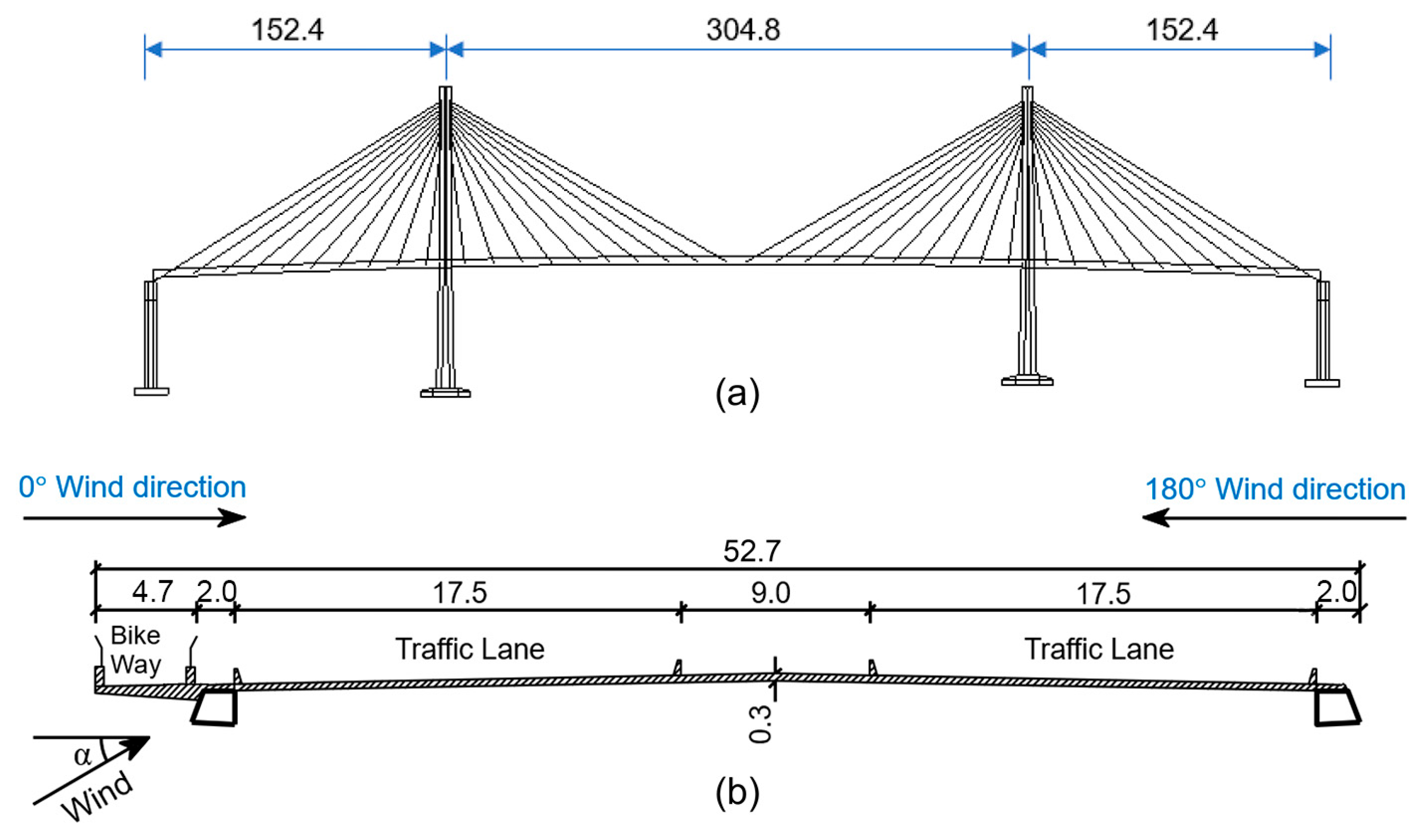
Figure 1. Schematic of cable-stayed bridge: (a) bridge general arrangement; (b) Π-shaped asymmetric girder section (unit: m).
Buildings 15 02824 g001
Figure 2. Schematic of suspension bridge: (a) bridge general arrangement; (b) asymmetric box girder section (unit: m).
Buildings 15 02824 g002
Figure 3. Wind tunnel test models: (a) asymmetric Π-shaped girder model; (b) asymmetric box girder model.
Buildings 15 02824 g003
Figure 4. Girder surface of section models: (a) asymmetric Π-shaped girder model; (b) asymmetric box girder model.
Buildings 15 02824 g004
Figure 5. Sign conventions for aerodynamic forces on (a) an asymmetric Π-shaped girder model; (b) an asymmetric box girder model.
Buildings 15 02824 g005
Figure 6. Procedure to identify the flutter derivatives of bridge girders.
Buildings 15 02824 g006
Figure 7. Experimental setup schematic for bridge girder dynamic testing.
Buildings 15 02824 g007
Figure 8. Computational domain and boundary conditions for (a) the Π-shaped girder; (b) the box girder.
Buildings 15 02824 g008
Figure 9. Close-up view of the grid system for (a) the Π-shaped girder; (b) the box girder.
Buildings 15 02824 g009
Figure 10. Comparison of static wind loading coefficients for (a) the Π-shaped girder; (b) the box girder.
Buildings 15 02824 g010
Figure 11. Static wind loading coefficients of the asymmetric Π-shaped girder.
Buildings 15 02824 g011
Figure 12. Mean velocity field and its streamlines for the asymmetric Π-shaped girder: (a) 0° WDA and (b) 180° WDA.
Buildings 15 02824 g012
Figure 13. Static wind loading coefficients of the asymmetric box girder.
Buildings 15 02824 g013
Figure 14. Flutter derivatives for the asymmetric Π-shaped girder at 0° (red square symbol) and 180° (blue circular symbol) WDAs.
Buildings 15 02824 g014
Figure 15. Flutter derivatives for the asymmetric box girder at 0° (red square symbol) and 180° (blue circular symbol) WDAs.
Buildings 15 02824 g015aBuildings 15 02824 g015b
Figure 16. RMS of heaving VIV displacements of the asymmetric Π-shaped girder. (a) 0° WDA; (b) 180° WDA.
Buildings 15 02824 g016
Figure 17. RMS of torsional VIV displacements of the asymmetric Π-shaped girder. (a) 0° WDA; (b) 180° WDA.
Buildings 15 02824 g017
Figure 18. Comparison of the instantaneous streamlines around the asymmetric Π-shaped girder under a −2.5° AOA: (a) 0° WDA and (b) 180° WDA.
Buildings 15 02824 g018
Figure 19. Critical flutter velocity of the asymmetric Π-shaped girder at different AOAs at 0° and 180° WDAs.
Buildings 15 02824 g019
Figure 20. Critical flutter velocity of the asymmetric box girder at different AOAs at 0° and 180° WDAs.
Buildings 15 02824 g020
Figure 21. Comparison of the instantaneous streamlines around the asymmetric Π-shaped girder at a 0° WDA: (a) 2.5° AOA and (b) −2.5° AOA.
Buildings 15 02824 g021
Figure 22. Comparison of the instantaneous streamlines around the asymmetric box girder at a 0° WDA: (a) 3° AOA and (b) −3° AOA.
Buildings 15 02824 g022
Table 1. Parameters of the flutter derivative identification test of the asymmetric Π-shaped girder.
ItemParameter and SymbolUnitPrototypeRatioModel
Equivalent massMass, mkg/m44,7001:45237.462
Mass moment of inertia, Jmkg·m2/m10,200,0001:4543.413
FrequenciesV–S–1, fhHz0.247-2.870
T–S–1, fθHz0.770-8.843
Damping ratiosHeaving, ζh%-10.373
Torsional, ζθ%-10.364
Table 2. Parameters of the flutter derivative identification test of the asymmetric box girder.
ItemParameter and SymbolUnitPrototypeRatioModel
Equivalent massMass, mkg/m86,3001:40253.938
Mass moment of inertia, Jmkg·m2/m4,370,0001:4041.707
FrequenciesV–S–1, fhHz0.148-1.309
T–S–1, fθHz0.409-3.702
Damping ratiosHeaving, ζh%-10.358
Torsional, ζθ%-10.371
Disclaimer/Publisher’s Note: The statements, opinions and data contained in all publications are solely those of the individual author(s) and contributor(s) and not of MDPI and/or the editor(s). MDPI and/or the editor(s) disclaim responsibility for any injury to people or property resulting from any ideas, methods, instructions or products referred to in the content.