Abstract
In freeform surface grid structures, quadrilateral meshes offer high visual transparency and simple joint connections, but their structural stability is relatively limited. To enhance stability, designers often introduce additional structural elements along the diagonals of the quadrilateral mesh, forming double-layer quadrilateral grid systems such as cable-braced gridshells. However, current design methodologies do not support the simultaneous optimization of both layers. As a result, the two layers are often designed independently in practical applications, leading to complex joint detailing that compromises construction efficiency, architectural aesthetics, and overall structural performance. To address these challenges, this study presents a weighted multi-objective geometry optimization framework based on a Guided-Projection algorithm. The proposed method integrates half-edge data structure and multiple geometric and structural constraints, enabling the simultaneous optimization of quadrilateral mesh planarity (i.e., panels lying on flat planes) and the orthogonality (i.e., angles approaching 90°) of diagonal cable layouts. Through multiple case studies, the method demonstrates significant improvements in panel planarity and cable orthogonality. The results also highlight the algorithm’s rapid convergence and high computational efficiency. Finite element analysis further validates the structural benefits of the optimized configurations, including reduced peak axial forces in cables, more uniform cable force distribution, and enhanced overall stiffness and buckling resistance. In conclusion, the method improves structural stability, constructability, and design efficiency, offering a practical tool for optimizing freeform cable-braced gridshells.
1. Introduction
With the continuous advancement of architectural design toward greater complexity, individuality, and enhanced spatial expression, freeform spatial grid structures have increasingly become essential components of contemporary architecture due to their smooth and expressive geometric forms. These structures have been widely adopted in high-end commercial complexes, cultural exhibition halls, and urban landmark buildings.
Freeform gridshells not only offer rich and diverse morphological possibilities but also exhibit lightweight and efficient structural performance. However, their complex geometries and highly varied structural systems impose significant challenges on the processes of design, analysis, and fabrication. Current research on freeform structures primarily focuses on optimizing modular design strategies to reduce manufacturing costs and simplify construction procedures [1].
In the context of façade systems, typical optimization directions include improving panel planarity [2], achieving spherical modularization of panels [3], and minimizing the number of unique panel modules [4]. For gridshell systems, common objectives include torsion-free joint optimization [5], equal-angle joint optimization [6], lamella planarity optimization [7], deployable straight-lamella layouts [8], and constant-curvature lamella configurations [9]. These optimization strategies are predominantly geometry-driven and aim to improve constructability and cost efficiency in practical applications.
In recent years, researchers have increasingly explored the potential of structural form optimization from the perspective of structural performance. Representative studies include structural design approaches based on specific mesh types, such as AAG meshes (with asymptotic networks, or A-nets, as the base mesh and one family of diagonals as geodesics), AGG meshes (with geodesic networks, or G-nets, as the base mesh and one family of diagonals as asymptotic curves), AGAG meshes (with G-nets as the base mesh and the diagonal mesh as A-net) [8], and PDA meshes (with A-nets as the base mesh and the diagonal mesh aligned with principal curvature directions) [10,11,12].
Each of these mesh types offers distinct advantages in terms of structural behavior and constructability. For example, A-nets arranged along asymptotic directions allow for the generation of developable lamellas that are orthogonal to the surface tangent plane; G-nets aligned with geodesic directions enable developable lamellas that are parallel to the tangent plane; P-nets aligned with principal curvature directions can produce developable lamellas that are either parallel or orthogonal to the tangent plane. All three types of lamellas are developable. Among them, the ones based on asymptotic and geodesic curves have straight edges, which further simplify the fabrication process. Furthermore, these mesh types can generate orthogonal networks over the surface, where elements parallel to the tangent plane contribute to in-plane stiffness, and elements orthogonal to the tangent plane enhance out-of-plane stiffness [10]. Such configurations balance the needs of modular construction with structural rationality.
In practical engineering applications, the structural forms of freeform surfaces are no longer limited to purely metallic or timber gridshells. An increasing number of projects adopt hybrid structures that combine metal or timber gridshells with tension cable systems. Single-layer gridshells are mainly compression-dominated structures. Their global stability is highly sensitive to factors such as geometry, member cross-sections, joint stiffness, and initial imperfections, making them vulnerable to global buckling. By introducing prestressed cables into metal or timber gridshells, diagonal bracing stiffness can be added to the quadrilateral mesh. The prestress and reverse deformation of the cables help partially offset the internal forces caused by external loads. This significantly improves the overall stiffness, load-bearing capacity, and stability of the structure, allowing it to span large-scale spaces. In this study, we specifically refer to such configurations, in which cables are added along the diagonal directions of a quadrilateral gridshell, as cable-braced gridshells.
Cable-braced gridshells can be categorized into timber-braced gridshells and steel-braced gridshells, depending on the material used for the quadrilateral gridshell. Representative case studies include the following:
- Mannheim Multihalle, Germany [13,14]: Built in 1975 with a maximum span of 60 m and a height of 20 m, it was the largest timber gridshell structure in the world at the time. Originally intended as a temporary structure with a lifespan of 20 years, local displacement of up to 70 cm was observed. Structural details and a site plan are shown in Figure 1a.
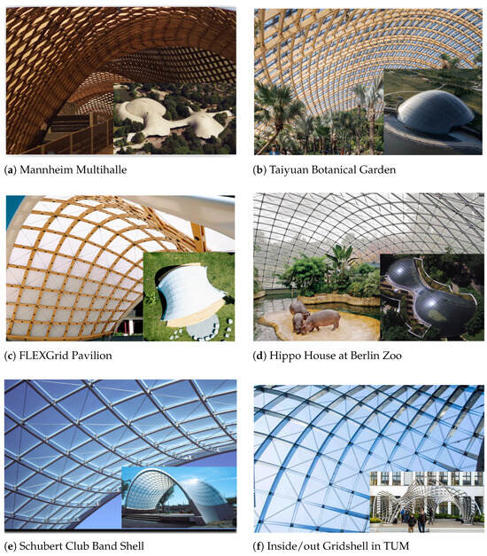 Figure 1. Examples of cable-braced gridshells.
 - Taiyuan Botanical Garden, China [15,16,17]: Completed in 2020, with a maximum span of 89.5 m and a height of 29.5 m, the structure adopts a timber gridshell with diagonal cable bracing. In contrast, due to the lack of a dual-layer mutually-diagonal cable layout, joints vary significantly and connections are complex. Structural details and a site plan are shown in Figure 1b.
- FLEXGrid Pavilion in Innsbruck, Austria [18,19]: Built in 2025, the structure was formed by assembling developable wooden lamellas in 2D and allowing them to pop-up into shape through elastic deformation. Structural details and a site plan are shown in Figure 1c.
- Hippo House at Berlin Zoo, Germany [20,21,22]: Completed in 1997, with a maximum span of 33 m and a height of 6 m, the structure employs a metal gridshell with diagonal cables. The mesh spacing is 1.2 m, and the boundary is supported by rigid concrete. The initial design surface is a translational surface, with a clear and smooth structural form. On the other hand, as the mesh is derived from an analytical surface rather than a numerically optimized freeform geometry, the design exhibits limited flexibility and lacks scalability. Structural details and a site plan are shown in Figure 1d.
- Schubert Club Band Shell, USA [23,24]: Built in 2002, with a maximum span of 15.2 m and a height of 3.4 m, the structure has a mesh spacing ranging from 0.8 to 1 m, and the diagonal cables have a diameter of 8 mm. Structural details and a site plan are shown in Figure 1e.
- Inside/out Gridshell in TUM, Germany [11]: Completed in 2017 with a maximum span of 10 m, the structure consists of mutually diagonal asymptotic and principal curvature networks laid on a minimal surface. Structural details and a site plan are shown in Figure 1f.
From the above cases and related studies, it can be observed that introducing diagonal cable networks to an existing quadrilateral gridshell can significantly improve structural load-bearing capacity and stability. As cable density increases, the performance enhancement becomes more pronounced. However, the cable network density should generally not exceed that of the quadrilateral gridshell. Adopting dual-layer mutually diagonal cable layouts helps simplify the design of joint connections.
It is important to note that most of the aforementioned cases are based primarily on quadrilateral gridshell design. The diagonal cable network was added only at the final stage for structural verification, rather than being integrated into a unified design optimization from the outset.
Focusing further on the design of cable-net structures, a review of existing freeform projects shows that many built examples use single-layer orthogonal cable arrangements. These systems are typically applied to geometrically simple surfaces with negative Gaussian curvature, such as saddle-shaped forms [25,26,27]. Notable examples include the National Speed Skating Oval [28,29] in China and the Yoyogi National Gymnasium [30,31] in Japan. These cases demonstrate that orthogonal cable networks offer several structural advantages, including clear load path definition, decoupled tension directions, high biaxial tensile stiffness with low deformability, symmetric prestressing with minimal construction deviation, and resistance to shear-induced buckling. Therefore, cable orthogonality is a critical consideration in cable net structure design. On the other hand, achieving optimized orthogonal cable layouts on freeform surfaces remains a significant challenge.
To address the two limitations identified in current cable-braced gridshell systems—namely, the lack of simultaneous optimization of the quadrilateral mesh and its diagonal network during early-stage design, and the absence of orthogonality considerations in cable layout—this study proposes a mesh optimization method based on the Guided-Projection (GP) [32] algorithm. The proposed approach allows for the simultaneous optimization of mesh planarity and diagonal cable orthogonality. It also supports multiple design constraints, including mesh fairness, closeness to a reference surface, and fixed boundary conditions. In doing so, it supports multi-objective geometric optimization for freeform structural systems.
Based on the optimized geometry, finite element (FE) simulations were conducted to evaluate and compare the mechanical performance of three structural schemes: the original quadrilateral gridshell, a cable-braced gridshell with planarity optimization only, and a cable-braced gridshell with both planarity and cable orthogonality optimization. The results indicate that the introduction of diagonal cables significantly enhances global stability. Moreover, further optimization of cable orthogonality improves the uniformity of force distribution within the cable system and increases structural efficiency. These findings confirm the effectiveness and practical value of the proposed optimization strategy in improving structural performance.
This research highlights the importance of integrating form and structure from the early stages of cable-braced gridshell design. The proposed method leverages geometric optimization to proactively guide the formation of structural logic, balancing architectural aesthetics with construction feasibility, fabrication simplicity, and mechanical performance. As a systematic and comprehensive design approach for complex freeform spatial structures, the optimization-driven design process presented here offers a transferable theoretical and practical foundation for the efficient realization of cable-braced gridshells.
2. Optimization Algorithm and Constraints
The optimization algorithm employed in this study is based on the Guided-Projection (GP) [32] framework. Section 2.1 introduces the constraint formulations under this algorithmic structure. Section 2.2 details the algorithmic structure, and Section 2.3 presents the optimization strategy.
2.1. Construction of Constrain Functions
The constraints considered in this study are categorized into two groups. The first group consists of primary geometric constraints, including the planarity constraint for quadrilateral meshes and the orthogonality constraint for the diagonal cable network. The second group includes design-intent-related geometric constraints, such as surface fairness, reference surface approximation, and boundary gliding.
2.1.1. Planarity Constraint
Conjugate curves typically appear in pairs on smooth surfaces and can be infinitely many. Given a curve and its direction, the corresponding conjugate curve can be determined using the Dupin indicatrix. For a smooth surface, if its parameterization satisfies
then the surface parameterization is considered a conjugate net [2,33]. The discretization of a conjugate net can be defined as a quadrilateral mesh composed of planar faces.
In practice, a smooth freeform surface is approximated by a finite number of planar quadrilaterals. To preserve conjugacy under discretization, the four vertices () of each quadrilateral face must be coplanar, lying on the same plane defined by a unit normal vector . The constraints are expressed as
The corresponding planarity energy term is given by
Here, denotes the number of quadrilateral faces, and is the unit normal of face f, as shown in Figure 2a.
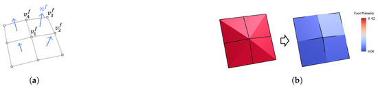
Figure 2.
Planarity constraint. (a) Geometric illustration of planarity constraint; (b) Optimization result based on planarity constraint.
This constraint formulation is simple and effective, and has been widely applied in discrete differential geometry for surface optimization and modeling, an optimization test case is shown as Figure 2b. The color indicate the face planarity.
2.1.2. Orthogonal Constraint
To define orthogonality over quadrilateral meshes, we adopt a condition that enforces equality between the lengths of the two diagonals in each quadrilateral face, thereby implicitly ensuring near-orthogonality [2,33,34].
We consider a general quadrilateral cell with vertices , ordered in a counter-clockwise fashion. Define the midpoint connectors as follows:
The diagonals are then
The diagonals are required to have equal length:
The associated energy term for orthogonality becomes
Here, are the vertices of quadrilateral face f.
The geometric illustration of orthogonal constraint is shown as Figure 3a, and an optimization test is shown as Figure 3b.
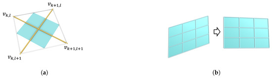
Figure 3.
Orthogonal constraint. (a) Geometric illustration of orthogonal constraint; (b) Optimization result based on orthogonal constraint.
2.1.3. Fairness Constraint
To ensure surface smoothness and avoid oscillatory behavior during optimization, we introduce a second-order difference-based fairness energy:
Here, , , and are three consecutive vertices on a polyline. This energy penalizes high curvature variations by minimizing the discrete approximation of the second derivative. Compared to traditional Laplacian smoothing, the second-order term more directly controls curvature oscillation. A smaller weight is typically assigned to avoid excessive flattening.
2.1.4. Surface Approximation Constraint
To meet design objectives, we introduce a reference surface approximation constraint. The user inputs a target reference mesh and an initial mesh surface. Each vertex on the initial mesh is constrained to remain close to the tangent plane of the nearest point on the target reference mesh. The constraint energy is defined as
Here, denotes the total number of vertices in the initial mesh, represents the closest point on the target reference mesh to the corresponding vertex on the initial mesh, and is the surface normal at . This constraint aims to minimize the distance between and the reference surface along the normal direction, thereby improving the approximation accuracy.
2.1.5. Boundary Gliding Constraint
To maintain boundary continuity and accommodate edge control, we enforce that boundary vertices of the initial mesh may only slide along the tangent direction of their nearest boundary point on the target reference mesh. Let be a boundary vertex on the initial mesh, and its nearest point on the target mesh boundary. Let be the tangent vector at (from the Frenet frame), and , be the normal and binormal vectors, respectively. The boundary gliding constraint energy is expressed as
which is equivalent to:
This constraint ensures boundary vertices move only along the tangential direction, effectively preventing irregular deformation at the mesh boundary.
2.2. Optimization Algorithm
This study proposes a multi-objective weighted optimization method based on the Guided-Projection (GP) [32] algorithm framework, specifically targeting the geometric optimization of quadrilateral meshes and their diagonal networks on freeform surfaces in cable-braced gridshell systems. The core of this framework is a weighted energy minimization scheme, which is highly extensible and adaptable to engineering applications.
The GP framework adopts a half-edge data structure to represent mesh topology, using vertex coordinates as the primary optimization variables. This data structure is especially well-suited for the task, as it facilitates the simultaneous optimization of both the primary mesh and its diagonal counterpart. Its efficient access to diagonal relationships greatly simplifies the construction of constraint functions.Depending on the types of constraints, auxiliary variables such as face normals and edge unit vectors are introduced to construct a complete optimization variable space. These variables are coupled through a set of constraint energy terms of at most quadric, which are then aggregated into a global energy function. The resulting problem is efficiently solved via an improved Gauss-Newton algorithm, reducing the optimization process to a sparse matrix system.
Based on this framework, the total energy function tailored for freeform cable-braced gridshell mesh optimization is formulated as
Here, denotes the planarity constraint energy, enforces orthogonality in diagonal directions, while the remaining three terms correspond to fairness, target reference surface approximation, and boundary gliding constraints, respectively. These energy components are weighted by coefficients , allowing flexible adjustment to accommodate varying design objectives. It is important to note that all constraint energy terms should be properly normalized during formulation. If different constraints operate on different scales, they may unintentionally dominate or be neglected in the optimization process. For example, in Equations (4)–(6), vector terms are normalized to unit length. This normalization is a key step to ensure balanced weighting when aggregating all energy terms.
Appendix A illustrates the pseudocode of the optimization algorithm. Each energy term follows a unified geometric formulation. By ensuring that all energy components are at most quadratic, the global energy function admits an analytical gradient, enabling efficient resolution via sparse linear solvers.
Additionally, the algorithm exhibits strong extensibility. In practical applications, more complex non-quadratic constraints can be incorporated by introducing auxiliary variables (e.g., normal vectors, local tangents, or bilinear coordinates) to reparameterize the system or by fixing certain local variables using previous iteration values, effectively reducing the order of the constraints. This strategy ensures computational efficiency while integrating various design constraints into a unified optimization framework.
2.3. Optimization Strategy
Building upon the geometric constraint models introduced in Section 2.1 and the optimization framework described in Section 2.2, the proposed strategy formulates a multi-objective optimization problem as a weighted combination of energy terms, with flexible control over the priority of each objective via user defined and tunable weight coefficients.
Specifically, planarity and orthogonality constraints, which are critical for ensuring the geometric accuracy of structural components, are defined as hard constraints. Their corresponding weights are fixed as constants (typically set to 1) to ensure that these constraints consistently dominate the direction of mesh adjustment throughout the entire optimization process. When the weight is set to a higher value, such as 10, the corresponding constraint will play a more dominant role in the optimization process. Assigning overly large weights to a single constraint is not recommended, as this can lead to unstable convergence. A more effective approach is to keep the weights balanced across all terms, allowing the optimization to converge gradually and reliably.
In contrast, fairness, reference surface approximation, and boundary gliding constraints are treated as soft constraints. The weight factors associated with the soft constraints are typically tested over several orders of magnitude, usually ranging from to depending on the design scenario. Different model sizes and geometries exhibit varying sensitivity to these weights, so tuning is necessary on a case-by-case basis. A practical strategy is to start with higher values and gradually reduce them. Empirically, a reasonable range falls between and .
Empirical results indicate that it is beneficial to emphasize the influence of soft constraints during the early stages of optimization in order to establish a favorable initial configuration. Once the mesh shape becomes stable, the weights of soft constraints can be gradually decreased or removed entirely, thereby reinforcing the convergence towards the hard constraint objectives.
3. Case Study
In the geometric optimization of freeform surface structures, characteristic curves such as asymptotic curves, geodesics [35,36], and principal curvature lines are typically treated as strong constraints. The performance and convergence of such constraint-driven optimization are highly dependent on the quality of the initial mesh. If the initial quadrilateral mesh lacks good directional alignment or uniform distribution, the optimization process often suffers from poor convergence and unstable results.
In contrast, optimization frameworks based on conjugate networks and orthogonal constraints are relatively weakly constrained. Their geometric formulation is simpler and more flexible, making them particularly suitable for form-finding within a broad design space. Such constraints are capable of accommodating complex surfaces with both positive and negative Gaussian curvature, while retaining a higher degree of geometric freedom under structurally reasonable conditions. For practitioners, adopting planarity and orthogonality control strategies requires less domain-specific knowledge, offering better engineering adaptability and practical feasibility.
To validate the performance of the proposed optimization algorithm under various requirements, a series of representative freeform surfaces were selected as target cases. These surfaces feature both positive and negative Gaussian curvature regions, which provide a robust setting for evaluating the algorithm’s adaptability under mixed curvature conditions. The selected surfaces and their corresponding Gaussian curvature distributions are illustrated in Figure 4, denoted as Case a, b, c, and d.
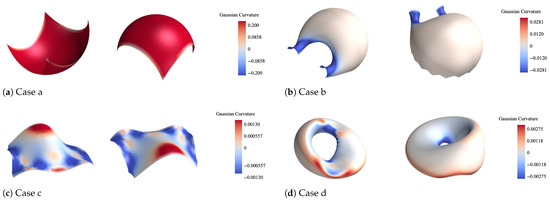
Figure 4.
Gaussian curvature distributions of four selected cases.
To quantitatively evaluate the effectiveness of planarity and orthogonality optimization, we define two metrics: P and O.
The metric P measures the maximum shortest distance between the two diagonals of each quadrilateral face, serving as an indicator of local non-coplanarity. For a quadrilateral face with vertices , define the diagonals as
The shortest distance between the diagonals is given by
To obtain a normalized metric, we divide this distance by the average length of the two diagonals:
The metric O quantifies the maximum angular deviation from orthogonality at mesh vertices. For a vertex , let and denote two intersecting edge vectors. The angle between them is
Then the orthogonality deviation is defined as
These two metrics allow for objective comparison of mesh configurations before and after optimization with respect to geometric planarity and directional regularity.
For the case studies shown in Figure 5a–d, we generated initial quadrilateral meshes using either UV meshn or mesh generation algorithms that allow user-defined mesh directions. These meshes were then optimized using the Guided-Projection-based framework introduced earlier, which simultaneously improves two diagonal quadrilateral meshes on the same surface. All numerical experiments were conducted on a computer with an Intel Core i7-8650U CPU @ 1.90GHz, 8GB RAM, and Windows 10 (64-bit).
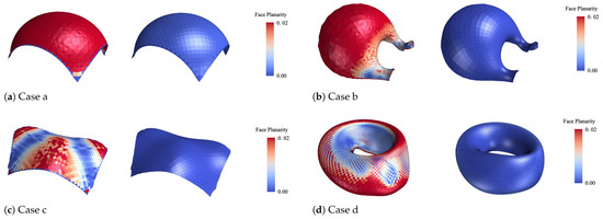
Figure 5.
Planarity optimization results of four selected cases.
Optimization data is summarized in Table 1, including the number of vertices, edges, and faces for each case, as well as the number of variables, constraint equations, constraint weights, total iteration steps, and runtime. The results show that the Guided-Projection algorithm achieves high efficiency across all cases. In each example, convergence was reached within 10 iterations and within 10 s of computation time. Comparing Cases a–d, we observe that the number of variables is the main factor affecting convergence speed, which demonstrates the algorithm’s strong adaptability to different mesh configurations.

Table 1.
Optimization parameters and performance summary of cases a–d.
Quantitative results of the optimization are reported in Table 2. After optimization, the planarity metric P improved by approximately 90%, and the orthogonality metric O of the diagonal meshes increased by over 70%, indicating strong optimization performance.
Table 2.
Planarity and orthogonality improvement summary.
Figure 5 and Figure 6 visualize the improvements in planarity and orthogonality, respectively. For clarity, the figures separately show the two quadrilateral meshes, although they are dual meshes sharing the same set of nodes on the same surface and were optimized simultaneously.
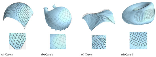
Figure 6.
Orthogonality optimization results of four selected cases.
In Figure 5, the planarity before and after optimization is shown: the left side displays the original mesh with poor planarity, while the right side shows the optimized mesh with significantly improved planarity.
In Figure 6, the orthogonality deviation for the four cases (a–d) is illustrated by the angular difference . In each subfigure, the top row shows a global view of the mesh comparison, while the bottom row presents a magnified local detail. Black lines represent the initial mesh, and cyan lines indicate the optimized result.
4. Structural Analysis
Based on numerous engineering cases [28,30] and related mechanical analyses [27], orthogonal cable nets tend to exhibit nearly isotropic structural behavior, while non-orthogonally arranged cable nets are typically anisotropic. As a result, orthogonal layouts generally lead to a more uniform distribution of cable forces. To further validate the effectiveness of orthogonality optimization in improving cable force uniformity, we selected the freeform surface of Case c, which features complex curvature regions, for in-depth analysis. Three structural configurations were compared:
- Case c1: Initial quadrilateral mesh without any diagonal bracing.
- Case c2: Planarized mesh with added diagonal cables, but without optimizing their arrangement.
- Case c3: Planarized mesh with further optimization to enforce diagonal orthogonality (termed 4-web optimized quadrilateral net).
The optimization parameters and performance for Case c2 and Case c3 are summarized in Table 3.
Table 3.
Optimization parameters and performance summary of cases c2–c3.
4.1. Simulation Setup
The three structural schemes were modeled and analyzed using Karamba3D 1.3.3. The material was selected as Q355 steel. All beams in the quadrilateral gridshell were modeled as rigidly connected, while the cable elements were modeled as axial-only truss members, hinged at both ends. Boundary conditions were applied by fully fixing all edge nodes. The load cases included self-weight, vertical dead load, and uniformly distributed initial cable prestress. Cable diameter was set to 5 mm. Compressive members were modeled as rectangular hollow sections of 20 cm × 40 cm with a 1 cm wall thickness. The overall span of the structure was 57 m.
4.2. Results and Comparison
Finite element analysis was performed for the three configurations to obtain maximum vertical displacement (small deformation analysis), first buckling mode and its corresponding eigenvalue (linear buckling analysis) [37]. Additionally, to quantify force uniformity, we define the following deviation metric:
where denotes the force in the i-th cable, and is the mean cable force. A smaller value of indicates a more uniform distribution of internal forces.
The comparison of Cases c1, c2, and c3 is summarized in Table 4. The results demonstrate that planarity optimization (Case c2) significantly improves geometric coplanarity, while orthogonality optimization (Case c3) further enhances the directional regularity of diagonals.
Table 4.
Comparison of geometry and structural performance.
From a structural performance perspective, Case c2 shows clear improvements over Case c1 after introducing diagonal cables. The vertical displacement is reduced by 40.12%, and the first buckling factor increases from 27.227 to 46.957, representing a 72.46% improvement. Case c3, after optimizing the orthogonality of the diagonal cable net, achieves a further reduction in maximum cable force (by approximately 25 kN) compared to Case c2. The force uniformity metric is also improved by 10.42%. In addition, a slight enhancement in buckling resistance is observed. Detailed numerical comparisons are provided in Table 4.
The stress distribution for Cases c1, c2, and c3 are illustrated in Figure 7. In Case c2, after adding diagonal cables, the peak axial force in compression members is reduced by 34.62% compared to Case c1. After further optimizing the orthogonality of the diagonal cables, the peak internal cable force decreases by an additional 7.46%. The first eight buckling modes of Case c3 are visualized in Figure 8, with Figure 8a–h representing the 1st through 8th modes, the shade of red indicates the degree of deformation difference from the original model. Compared to Case c2, the buckling modes in Case c3 remain nearly unchanged after the orthogonality optimization. These modes were obtained through linear eigenvalue buckling analysis, indicating the primary instability patterns of the optimized cable-braced gridshell.
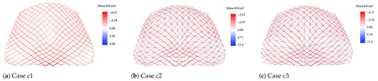
Figure 7.
Stress distribution for Cases c1–c3.
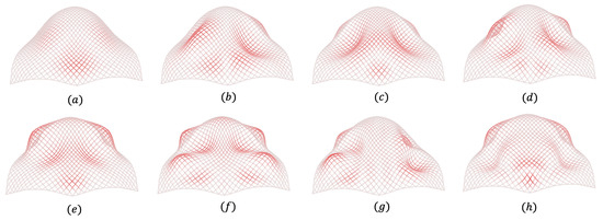
Figure 8.
The first eight buckling modes of Case c3.
The above analysis demonstrates that the introduction of diagonal cables leads to a substantial increase in the first buckling eigenvalue, indicating a corresponding enhancement in structural stability. Furthermore, optimizing the orthogonality of the cable layout significantly reduces the maximum cable force and results in a more uniform force distribution, thereby improving material utilization efficiency.
5. Conclusions
Freeform cable-braced gridshells represent a promising structural typology in contemporary architecture, offering a combination of expressive geometries and lightweight structural behavior. In contrast, the inherent geometric complexity and structural sensitivity of such systems pose significant challenges in design and optimization. Traditional methods often rely on strong constraints based on feature curves such as geodesics or asymptotic lines. These approaches, while mathematically rigorous, are highly sensitive to initial mesh quality and often lack robustness when applied to surfaces with mixed Gaussian curvature.
In this work, we propose a flexible optimization framework based on weak geometric constraints—planarity and diagonal orthogonality—which can be simultaneously satisfied through a unified Guided-Projection algorithm. This formulation avoids over-reliance on the initial mesh directionality, improves convergence behavior, and exhibits strong adaptability across a wide variety of freeform surface typologies. As demonstrated by Cases a–d (see Table 1 and Table 2), the method achieves significant improvement in geometric rationalization within just a few iterations, with all optimizations converging in under 10 steps and less than 10 seconds.
From a structural performance perspective, the inclusion of diagonal cables enhances both stiffness and stability. Particularly, orthogonality optimization improves the regularity of cable arrangements and reduces peak cable axial forces. This was evident in the comparison of Cases c1–c3, where the planarity and orthogonality optimization collectively led to reduced displacement, improved buckling load factor, and a more uniform cable force distribution (Table 4). The proposed cable deviation metric further quantifies this improvement, revealing a measurable enhancement in structural efficiency and material utilization.
For designers, the proposed optimization framework provides a practical and effective tool for optimizing cable-braced gridshells. It considers multiple objectives, including surface approximation and boundary constraints, making it well-suited for real-world design applications.
6. Discussion
Nonetheless, the study has several limitations and areas for future exploration. For instance, in Case c2, the diagonal cable layout already possessed relatively smooth directional flow due to the underlying mesh optimization. This limited the observable gain in cable force uniformity when transitioning to Case c3. It is expected that in more irregular or zigzag mesh configurations, the benefit of orthogonality optimization would be more pronounced. Further benchmarking on more complex initial conditions could validate this hypothesis.
Moreover, this study focuses on conceptual-level structural modeling and does not account for the detailing of cable clamp joints. The transition of cable forces before and after tensioning, especially under extreme load cases, was not addressed. These factors are critical for practical deployment and should be examined through high-fidelity finite element modeling and mechanical testing in future work [38]. Development of rational joint designs that integrate architectural feasibility, fabrication constraints, and mechanical performance will be a crucial step toward realizing such structures at scale [39].
In conclusion, this work demonstrates the feasibility and efficiency of using a geometry-driven optimization approach for the integrated design of freeform cable-braced gridshells. The framework shows strong potential for supporting early-stage design iteration, balancing geometric regularity with structural robustness. Extensions to fabrication-aware optimization and construction-integrated modeling remain important future directions.
Author Contributions
Conceptualization, X.L.; methodology, X.L.; software, X.L.; validation, X.L.; formal analysis, X.L.; investigation, X.L.; resources, X.L.; data curation, X.L.; writing—original draft preparation, X.L.; writing—review and editing, Q.Z.; visualization, X.L.; supervision, Q.Z.; project administration, Q.Z.; funding acquisition, Q.Z. All authors have read and agreed to the published version of the manuscript.
Funding
This research received no external funding.
Data Availability Statement
The data presented in this study are available from the corresponding author on request.
Acknowledgments
We wish to thank the anonymous reviewers for their helpful comments, and the authors of [Dellinger et al. 2023] [6] and [Laccone et al. 2024] [40] for the testing surfaces.
Conflicts of Interest
The authors declare no conflicts of interest.
Appendix A
| Algorithm A1 Optimization algorithm for a cable-braced gridshell on freeform surfaces. |
|
References
- Pottmann, H.; Asperl, A.; Hofer, M.; Kilian, A. Architectural Geometry; Bentley Institute Press: Exton, PA, USA, 2007. [Google Scholar]
- Liu, Y.; Pottmann, H.; Wallner, J.; Yang, Y.L.; Wang, W. Geometric modeling with conical meshes and developable surfaces. ACM Trans. Graph. 2006, 25, 681–689. [Google Scholar] [CrossRef]
- Kilian, M.; Cisneros, A.S.R.; Müller, C.; Pottmann, H. Meshes with Spherical Faces. ACM Trans. Graph. 2023, 42, 184:1–184:19. [Google Scholar] [CrossRef]
- Kilian, M.; Pellis, D.; Wallner, J.; Pottmann, H. Material-minimizing forms and structures. ACM Trans. Graph. 2017, 36, 173. [Google Scholar] [CrossRef]
- Pottmann, H.; Liu, Y.; Wallner, J.; Bobenko, A.; Wang, W. Geometry of multi-layer freeform structures for architecture. ACM Trans. Graph. 2007, 26, 65. [Google Scholar] [CrossRef]
- Dellinger, F.; Li, X.; Wang, H. Discrete orthogonal structures. Comput. Graph. 2023, 114, 126–137. [Google Scholar] [CrossRef]
- Jiang, C.; Wang, C.; Tellier, X.; Wallner, J.; Pottmann, H. Planar Panels and Planar Supporting Beams in Architectural Structures. ACM Trans. Graph. 2023, 42, 19. [Google Scholar] [CrossRef]
- Schling, E.; Wang, H.; Hoyer, S.; Pottmann, H. Designing Asymptotic Geodesic Hybrid Gridshells. Comput.-Aided Des. 2022, 152, 103378. [Google Scholar] [CrossRef]
- Kilian, M.; Wang, H.; Schling, E.; Schikore, J.; Pottmann, H. Curved support structures and meshes with spherical vertex stars. In Proceedings of the ACM SIGGRAPH 2018 Posters, Vancouver, BC, Canada, 10–11 August 2018; pp. 1–2. [Google Scholar] [CrossRef]
- Xinye, L.; Mansouri, M.; Elshafei, A. Conformal Principal-Asymptotic Elastic Gridshells: Parametric Design and Modular Construction. 2025; preprint. [Google Scholar] [CrossRef]
- Schling, E.; Hitrec, D.; Schikore, J.; Barthel, R. Design and construction of the asymptotic pavilion. In Proceedings of the 8th International Conference on Textile Composites and Inflatable Structures, Munich, Germany, 9–11 October 2017; International Center for Numerical Methods in Engineering: Barcelona, Spain; pp. 178–189. [Google Scholar]
- Schling, E.; Wan, Z. A geometry-based design approach and structural behaviour for an asymptotic curtain wall system. J. Build. Eng. 2022, 52, 104432. [Google Scholar] [CrossRef]
- Wenzel, F. Multihalle Mannheim. Bautechnik 2019, 96, 21–24. [Google Scholar] [CrossRef]
- Mannheim Multihalle–Denken Forschen Entwickeln. Available online: https://mannheim-multihalle.de/en/homepage/#programmstart (accessed on 5 July 2025).
- Wang, G.; Zhang, L.; Xu, C.; Zhang, S.; Zhou, Z.; Guo, S.; Ji, X.; Lei, H. Analysis of factors affecting the stability of large-span cable-braced timber gridshells. Dev. Built Environ. 2024, 17, 100360. [Google Scholar] [CrossRef]
- Jia, S.; Li, R.; Shi, S. Design Practice of Large-Span Spatial Structures Using Glulam. Build. Struct. 2023, 53, 9–15, 120. [Google Scholar] [CrossRef]
- Jia, S. Key Technologies in the Structural Design of Large-Span Glulam Grid Shells for Taiyuan Botanical Garden. Build. Struct. 2022, 52, 62. [Google Scholar] [CrossRef]
- Pillwein, S.; Musialski, P. Generalized deployable elastic geodesic grids. ACM Trans. Graph. 2021, 40, 271:1–271:15. [Google Scholar] [CrossRef]
- FLEXGrid Pop-Up-Pavillon. Available online: https://beyondbending.at/portfolio/flexgrid-pop-up-pavillon/ (accessed on 5 July 2025).
- Schlaich, J.; Schober, H. Glaskuppel für die Flußpferde im Zoo Berlin. Stahlbau 1998, 67, 307–312. [Google Scholar] [CrossRef]
- Schlaich, J.; Schober, H. Glass Roof for the Hippo House at the Berlin Zoo. Struct. Eng. Int. 1997, 7, 252–254. [Google Scholar] [CrossRef]
- House for Hippopotamus, Zoo Berlin. Available online: https://www.sbp.de/en/project/house-for-hippopotamus-zoo-berlin/ (accessed on 5 July 2025).
- McCormick, S.; Besjak, C.; Korista, D.S.; Baker, W. Shell of Steel. Civ. Eng. 2003, 73, 68–73. [Google Scholar]
- Mccormick, S.; Besjak, C.; Korista, D.S.; Baker, W. Schubert Club Band Shell, Saint Paul, Minnesota, USA. Struct. Eng. Int. 2004, 14, 140–141. [Google Scholar] [CrossRef]
- Zhang, N.; Luo, B.; Zhu, L.; Liu, X. Research on the forming technology of a novel type structure of double-layer orthogonal cable net with a large opening. Structures 2024, 63, 106371. [Google Scholar] [CrossRef]
- Wu, J.; Yan, B.; Sun, G.; Liu, M.; Li, Y.; Zhou, C. Research on the Construction-Forming Model of a Single-Layer Orthogonal Saddle-Shaped Cable Net with an Opening. J. Constr. Eng. Manag. 2025, 151, 05025008. [Google Scholar] [CrossRef]
- Sun, G.; Ma, X.; Zhou, C.; Liu, M.; Li, Y.; Wu, J. Experimental study on the static performance of single-layer orthogonal saddle-shaped cable net structure with large openings. J. Build. Eng. 2025, 111, 113057. [Google Scholar] [CrossRef]
- Yang, Y.; Chen, B.; Zhu, Z.; Shen, L.; Xi, Q.; Duan, S.; Zhou, Z.; Ge, D. Structural Design of the National Speed Skating Oval. Build. Struct. 2018, 48, 1–4. [Google Scholar] [CrossRef]
- Wang, Z.; Bai, G.; Chen, B.; Zhu, Z.; Shen, L.; Wang, Y.; Xing, J.; Yang, Y. Steel Structure Design of the National Speed Skating Oval. Build. Struct. 2018, 48, 5–11. [Google Scholar] [CrossRef]
- Tsuboi, Y.; Kawaguchi, M. The analysis and design of a suspension roof structure. In Proceedings of the International Conference on Space Structures, Guildford, UK, 1 September 1966; pp. 925–945. [Google Scholar]
- Thiele, F. Zwei Sporthallen in Tokio. Stahlbau 1964, 33, 126. [Google Scholar]
- Tang, C.; Sun, X.; Gomes, A.; Wallner, J.; Pottmann, H. Form-finding with polyhedral meshes made simple. ACM Trans. Graph. 2014, 33, 70. [Google Scholar] [CrossRef]
- Bobenko, A.I.; Suris, Y.B. Discrete Differential Geometry: Integrable Structure; Number Vol. 98 in Graduate Studies in Mathematics; American Mathematical Society: Providence, RI, USA, 2008. [Google Scholar]
- Peng, C.H.; Jiang, C.; Wonka, P.; Pottmann, H. Checkerboard patterns with black rectangles. ACM Trans. Graph. 2019, 38, 171. [Google Scholar] [CrossRef]
- Rabinovich, M.; Hoffmann, T.; Sorkine-Hornung, O. Discrete Geodesic Nets for Modeling Developable Surfaces. ACM Trans. Graph. 2018, 37, 16. [Google Scholar] [CrossRef]
- Wang, H.; Pellis, D.; Rist, F.; Pottmann, H.; Müller, C. Discrete geodesic parallel coordinates. ACM Trans. Graph. 2019, 38, 173. [Google Scholar] [CrossRef]
- Bulenda, T.; Knippers, J. Stability of grid shells. Comput. Struct. 2001, 79, 1161–1174. [Google Scholar] [CrossRef]
- Wan, Z.; Schling, E. Structural principles of an asymptotic lamella curtain wall. Thin-Walled Struct. 2022, 180, 109772. [Google Scholar] [CrossRef]
- Wan, Z.; Schling, E. Structural behaviour of an asymptotic curtain wall stiffened with lamella couplings. J. Constr. Steel Res. 2023, 207, 107938. [Google Scholar] [CrossRef]
- Laccone, F.; Pietroni, N.; Cignoni, P.; Malomo, L. Bending-reinforced grid shells for free-form architectural surfaces. Comput.-Aided Des. 2024, 168, 103670. [Google Scholar] [CrossRef]
Disclaimer/Publisher’s Note: The statements, opinions and data contained in all publications are solely those of the individual author(s) and contributor(s) and not of MDPI and/or the editor(s). MDPI and/or the editor(s) disclaim responsibility for any injury to people or property resulting from any ideas, methods, instructions or products referred to in the content. |
© 2025 by the authors. Licensee MDPI, Basel, Switzerland. This article is an open access article distributed under the terms and conditions of the Creative Commons Attribution (CC BY) license (https://creativecommons.org/licenses/by/4.0/).