Article

Study on the Mechanical Response of FSP-IV Steel Sheet Pile Cofferdam and the Collaborative Mechanism of Sediment Control Technology in the Nenjiang Water Intake Project

1
Anhui Province Key Laboratory of Building Structure and Underground Engineering, Anhui Jianzhu University, Hefei 230601, China
2
The First Engineering Co., Ltd., CTCE Group, Hefei 230023, China
3
Chengji Railway Engineering Technology Limited Company, Hefei 230051, China
*
Author to whom correspondence should be addressed.
Buildings 2025, 15(15), 2610; https://doi.org/10.3390/buildings15152610
Submission received: 20 June 2025 / Revised: 17 July 2025 / Accepted: 21 July 2025 / Published: 23 July 2025
(This article belongs to the Section Building Structures)

Abstract

In response to the dual challenges of the mechanical behavior of steel sheet pile cofferdam and sediment control in urban water intake projects, a multi-method integrated study was conducted based on the Nenjiang Project. The results show that the peak stress of FSP-IV steel sheet piles (64.3 MPa) is located at a depth of 5.5–8.0 m in the center of the foundation pit, and that the maximum horizontal displacement (6.96 mm) occurs at the middle of the side span of the F pile. The internal support stress increases with depth, reaching 87.2 MPa at the bottom, with significant stress concentration at the connection of the surrounding girder. The lack of support or excessively large spacing leads to insufficient stiffness at the side span (5.3 mm displacement at the F point) and right-angle area (B/H point). The simultaneously developed sediment control integrated system, through double-line water intake, layered placement of the geotextile filter, and the collaborative construction of the water intake hole–filter layer system, achieves a 75% reduction in sediment content and a decrease in standard deviation. This approach ensures stable water quality and continuous water supply, ultimately forming a systematic solution for water intake in high-sediment rivers.

1. Introduction

As urbanization accelerates, the demand for water and the requirement for water quality have been increasing. Infiltration channel water intake, as one of the main water extraction methods, has unique advantages [1,2,3], especially in areas with poor water quality and abundant groundwater resources. However, infiltration channel water intake in high-turbidity river areas faces dual challenges: the stability of the support system and sediment control. On the one hand, the high water levels and weak geological conditions of riverbank infiltration channels can lead to support instability. On the other hand, high-sediment water flow threatens the stability of the water supply by causing clogging in the filter layer. Steel sheet pile cofferdams, as the most commonly used support structure in infiltration channel construction, offer advantages such as impermeability and ease of construction [4,5,6], but the mechanical response mechanism of the cofferdam in infiltration channel projects is still unclear. Existing studies mainly focus on conventional conditions and lack research on stress–displacement evolution and failure mechanisms under the unique loads of infiltration channels [7]. At the same time, sediment control technologies also have limitations. Traditional filter layer designs [8], such as geotextile studies, struggle to adapt to high-sediment dynamic flows, and sediment control at intake points [9] lacks synergy with the supporting structure.
Regarding the support issues in infiltration channel water intake, steel sheet piles, with their excellent soil retention and water stopping capabilities, have become the mainstream solution [10,11,12,13]. However, current studies mostly focus on static conditions. Athanasopoulos et al. [14] explored the installation and performance of laterally supported steel sheet piles using a vibration-driven pile installation machine in sensitive urban environments. They found that the installation of these steel sheet piles requires the absence of thick gravel layers in the site stratigraphy and the monitoring of ground vibrations during installation. Lee et al. [15] investigated the performance of steel sheet piles in different environments through 3D finite element analysis, deeply studying collapse issues and the impact of soil flow on pre-installed piles in excavation areas. Zhou Xinya et al. [16] used position-guided frames and planar positioning frames to insert steel sheet piles, and observed that the maximum deformation occurred at the top of the pile, caused by water flow on the windward side. Movahedi Rad [17] used reliability-based limit analysis to evaluate the lateral load-bearing capacity of long piles with free heads and fixed heads during plastic limit analysis. However, the existing research on the mechanical response mechanisms of steel sheet piles in high-sediment and high-permeability environments is still insufficient [18,19,20,21], especially the lack of quantitative analysis on the effect of flow-induced seepage pressure on the support system.
Regarding sediment control requirements in infiltration channel water intake, many scholars and engineers have conducted extensive research on sediment control technologies within infiltration water intake systems to address design issues of key facilities such as filter layers, large wells, and pre-sedimentation tanks, with significant achievements in practical engineering [22,23,24,25]. Amin et al. [26], through investigations of qanat wells in the Jeddah/Makkah region of Western Saudi Arabia, demonstrated that the performance of the filter layer (an important component of the permeable system) directly affects the system’s efficiency and lifespan. Xu et al. [27], based on long-term permeability tests of silty clay filtered via nonwoven geotextile, proposed theoretical equations for the permeability coefficient of nonwoven geotextile under clogging conditions and summarized the filtration mechanism of geotextile opening size and thickness. Michell [28] successfully controlled and resolved sediment issues by using erosion-promoting vanes, skimming walls, and realigning the riverbank upstream of the intake. In similar engineering practices, it is evident that optimizing the filter layer is crucial to ensuring water quality. However, existing technologies struggle to balance the safety of the support structure and the effectiveness of the filter layer.
The above discussion highlights the deficiencies in current research regarding the mechanical response mechanisms of steel sheet piles and the optimization of filter layers. This paper uses the Nenjiang Water Intake Project as a case study, employing numerical simulations and theoretical analysis to integrate multi-scale methods. It reveals the stress–displacement distribution of FSP-IV steel sheet piles and clarifies the stress distribution characteristics and displacement evolution patterns. The study also innovatively integrates double-line water intake technology, dynamic compensation of the filter layer, and collaborative construction of the intake hole–filter layer system to build a collaborative control system for supporting structure stability and water quality assurance. The research findings provide technical support for the smooth implementation of the project and serve as a reference model for similar projects.

2. Research Background

2.1. Project Overview

The Nenjiang Urban Water Supply Project is located within the Nenjiang Town area of Heihe City, with the intake location in the main channel of the Nenjiang River, at geographic coordinates 125°13′5.0″ E and 49°13′10″ N. The surface water source for the supply area is the main channel of the Nenjiang River, and the underground water source is from Nenjiang groundwater. The water intake project consists of surface water extraction, underground water extraction, intake head, and intake pumping station. The underground water extraction includes a 1556 m infiltration channel, a 1210.9 m water intake pipeline, 33 inspection wells, 4 large wells with a diameter of 6.0 m, 1 intake head, and 1 pumping station. The underground water extraction infiltration channel is located on the Nenjiang riverbed and floodplain. The riverbed section has a parallel waterway construction length of 1106 m, and the floodplain section has a vertical infiltration channel construction length of 450 m. This infiltration channel is connected to the intake pumping station by a 371 m underground water intake pipeline. The surface water intake head is located 2700 m upstream of the Lama River confluence on the left bank of the main channel. The intake head has a diamond-shaped structure with dimensions of 10.35 m by 3 m, and the surface water intake pipeline, 841 m long, connects the intake head to the pumping station, as shown in Figure 1.

2.2. Geological Environmental Characteristics

The project site is located in the Nenjiang River Basin, with a basin area of approximately 298,500 km2. It is part of a flat and low-lying river terrace area with a generally gentle topography, wide riverbeds, and relatively stable shorelines. The regional geomorphological units are primarily alluvial fans and plains, with the surface mainly covered by alluvial deposits, exhibiting typical river alluvial terrace characteristics. The site is situated within the geological structural unit of the Xing’anling—Inner Mongolia Tectonic Depression Zone, specifically the Xiaoxing’anling–Songnen Block (III) and the Songnen Fault Depression Zone (III3). Since the Mesozoic, the region has experienced significant subsidence, leading to the deposition of thick continental sediments. Since the late Cenozoic, new tectonic movements have shown periodic or intermittent oscillatory characteristics. The primary fault in the area is the Nenjiang Fault, which extends along the Nenjiang River in the northern region, showing no recent activity. According to the “China Seismic Ground Motion Parameter Zoning Map” (GB 18306-2015) [29], the project area has a basic seismic peak acceleration of 0.05 g, with a seismic response spectrum characteristic period of 0.35 s. The corresponding seismic basic intensity is VI, indicating good regional tectonic stability. The stratigraphy at the project site consists, from top to bottom, of Quaternary, Upper Pleistocene, and Middle Pleistocene layers. The stratigraphic formation is mainly alluvial. The Quaternary layer at the surface consists of yellow low (high)-plasticity clay, sandy low-plasticity clay, fine-grained sandy silt, poorly graded fine sand, and gray low-plasticity clay, which is distributed in the upper part of the floodplain area. The lower part, consisting of Upper Pleistocene and Middle Pleistocene alluvial layers, is primarily composed of coarse sand, gravel, and cobbles, located beneath the Quaternary layer in the floodplain area and terrace regions. Through on-site sampling and conducting soil triaxial and direct shear tests, the geotechnical physical and mechanical parameters of the strata were measured, as shown in Table 1.
The water intake for the Nenjiang Urban Water Supply Project is located in the main channel of the Nenjiang River on the northwest side of Nenjiang City. The groundwater type in the region is primarily phreatic water, with localized occurrences of weak confined water. The aquifer consists of sand, gravel, and other materials from the Upper Pleistocene to the Holocene, with relatively coarse particles and good permeability. The permeability coefficient typically ranges from 5 m/d to 100 m/d. The aquifer thickness is approximately 6–15 m, with groundwater depths ranging from 1.43 to 2.75 m. The main source of groundwater replenishment is vertical recharge from atmospheric precipitation, with lateral runoff supplementation as a secondary source. Groundwater discharge primarily occurs through lateral runoff and evaporation.

3. Mechanical Response of the Infiltration Channel Steel Sheet Pile Cofferdam

3.1. Basic Characteristics of the Infiltration Channel Steel Sheet Pile Cofferdam

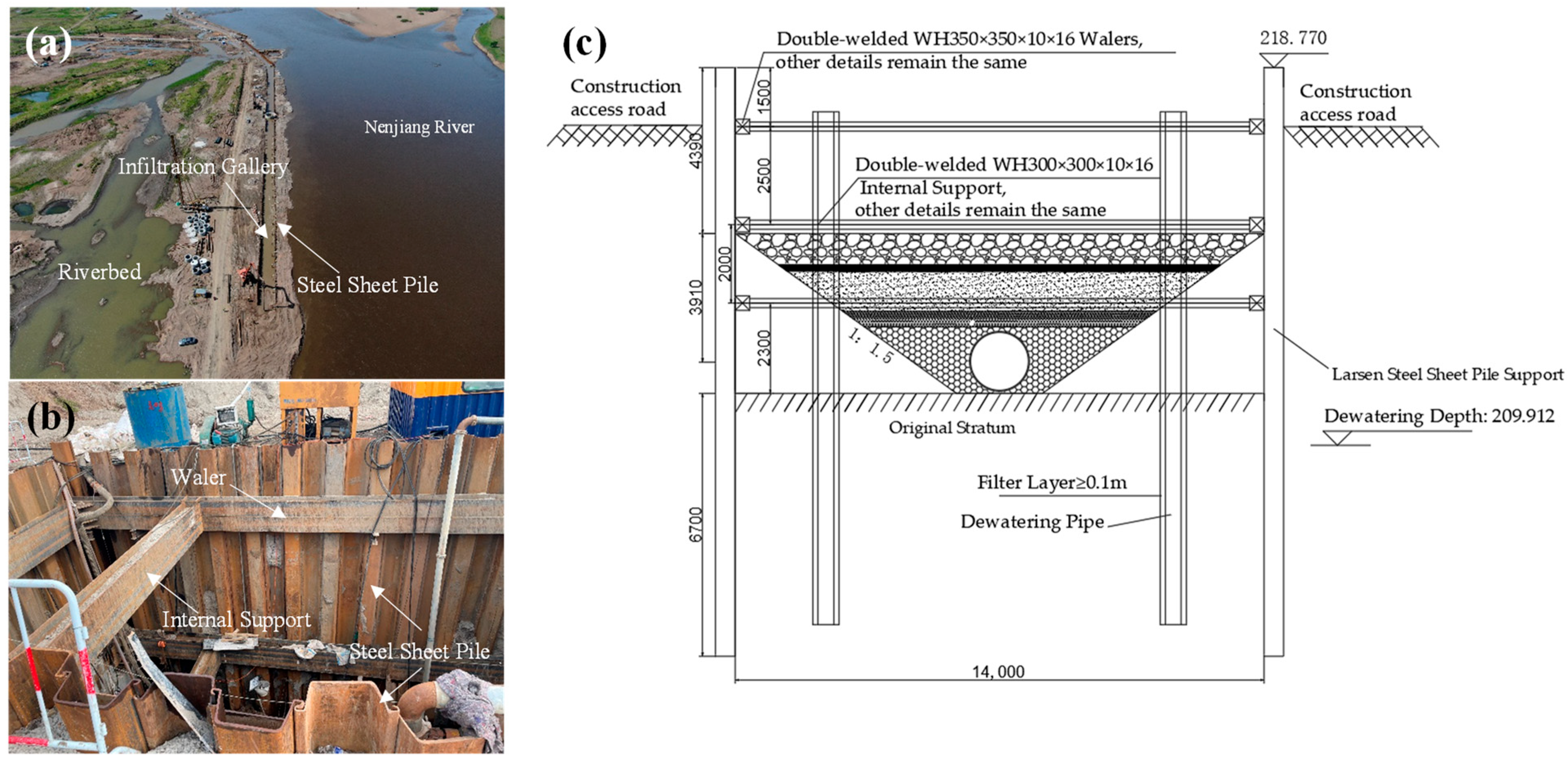
The Nenjiang Urban Water Supply Project involves the excavation of a deep foundation pit for the riverbank water intake infiltration channel, with a width of 14.5 m and a depth of 8.3 m. During construction, the top of the piles is raised 1.5 m above the water level. The excavation of the infiltration channel is carried out in layers, with a total of four layers. The excavation depths for each layer are 1.5 m, 2.5 m, 2.0 m, and 2.3 m, respectively. The retaining structure for the infiltration channel uses FSP-IV steel sheet piles, while the surrounding girder is constructed with 2HW 700 mm × 300 mm × 13 mm × 24 mm H-beams. The internal supports are made of double-spliced WH 300 mm × 300 mm × 10 mm × 16 mm steel supports, with horizontal spacing of 6 m and three vertical steel supports. The first vertical support is located 1.5 m below the top of the piles. The distance between the first and second vertical supports is 2.5 m, and the distance between the second and third vertical supports is 2.0 m, as shown in Figure 2.

3.2. Calculation Model and Parameters

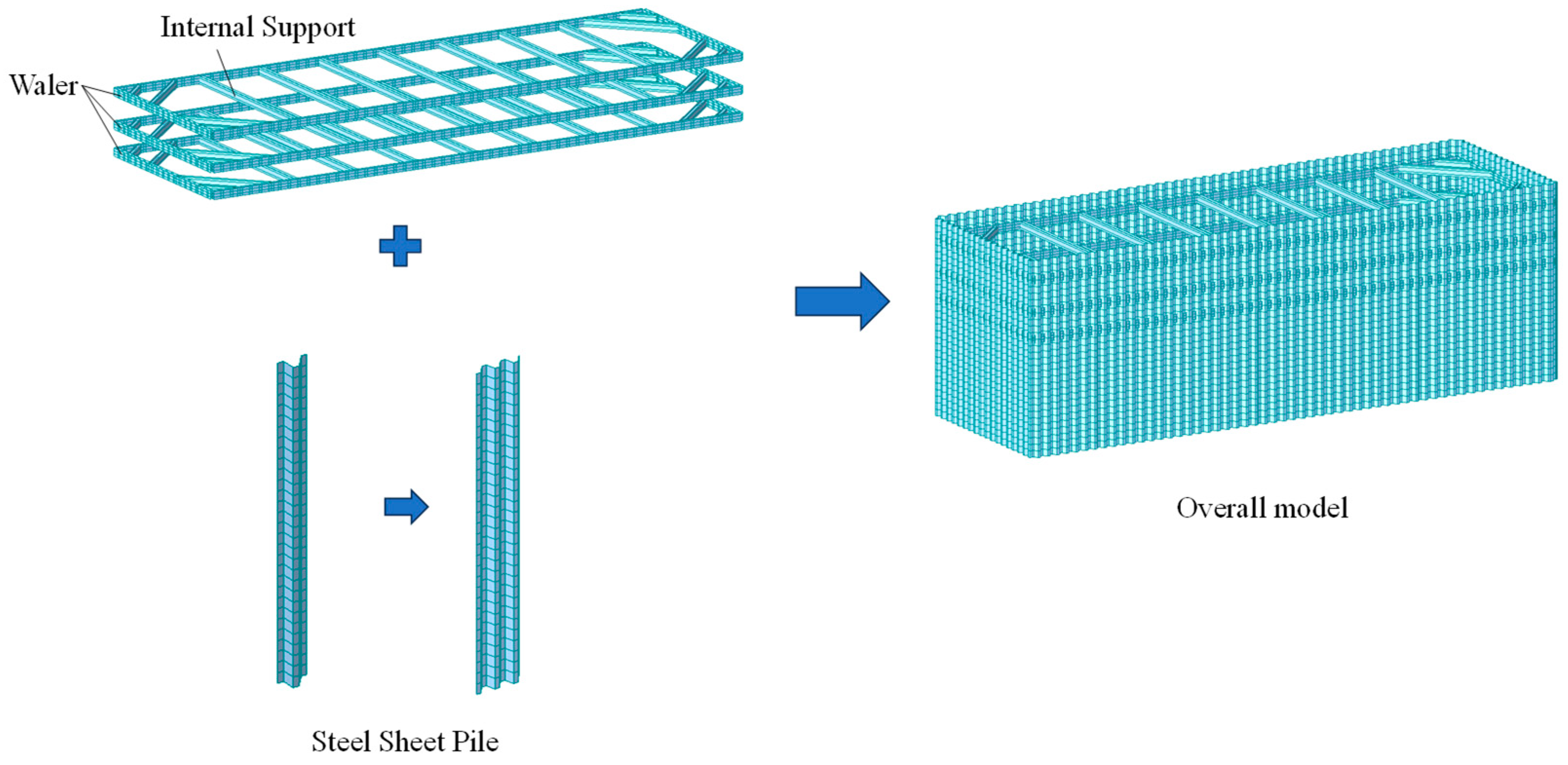
The study of the mechanical characteristics of the steel sheet pile cofferdam during the water intake project construction is based on the deep foundation pit of the infiltration channel. The segment length of the steel sheet pile cofferdam construction is taken as 44 m, and a finite element numerical calculation model is established using Midas Civil 2022 (v1.2) software [30,31,32,33]. In the model, the steel sheet piles are represented by plate elements, and the mesh is divided with dimensions of 0.5 m × 0.2 m, resulting in a total of 18,220 nodes and 18,546 elements. The internal supports and surrounding girders are represented by beam elements, with 966 elements in total. An elastic connection is applied between the steel sheet piles and the surrounding girder. The bottom of the steel sheet pile is constrained as a hinged support, and passive soil pressure is simulated using soil springs, as shown in Figure 3.
The numerical calculation model is constructed in five main steps as follows:
Step 1: Set up the basic parameters of the project, including units, coordinate system, and analysis type. Define material properties and establish the Q345 steel type. Define the cross-sectional shapes of the elements, with the steel sheet piles defined as plate elements and the surrounding girder and internal supports defined as double-spliced H-shaped steel elements with dimensions of 2HW 700 mm × 300 mm × 13 mm × 24 mm and 2WH 300 mm × 300 mm × 10 mm × 16 mm, respectively;
Step 2: Import the pre-completed CAD files used for modeling. Establish the steel sheet pile element model and the three internal support unit models for different construction stages, dividing them into a 0.5 m × 0.2 m grid;
Step 3: Set the boundary conditions. The bottom of the steel sheet piles is defined as a hinged support, and soil spring models are set below the excavation surface. Node elastic support is used to simulate the soil springs. The calculated soil spring data is input into the model, and soil spring models for construction stages one, two, and three are set;
Step 4: Use the soil–water interaction method to calculate the soil pressure and water pressure acting on the steel sheet piles. Select the static load model, and apply the loads for stages one, two, and three to the steel sheet pile model;
Step 5: Set the load combinations. According to the “Building foundation pit support design regulations” [34], set the strength combination partial factor to 1.25 and the stiffness combination partial factor to 1.0. Run the analysis and check the results, including stress, shear force, displacement, and other structural behaviors.
The stratigraphic division of the numerical calculation model is based on the geological survey data. The thickness of the construction road embankment layer is taken as 3 m, the thickness of the gravel layer is 6.0 m, and the sandstone layer thickness exceeds 4.5 m. The soil forces acting on the inner and outer sides of the steel sheet pile are applied in accordance with the soil–water interaction method, as shown in Equations (1) to (3).
p a = γ z t a n 2 45 φ 2 + 2 c t a n 45 φ 2
p b = γ z t a n 2 45 + φ 2 + 2 c t a n 45 + φ 2
p w = ρ w g h
where p a is the active earth pressure (kPa); p b is the passive earth pressure (kPa); p w is the water pressure (kPa); γ is the natural unit weight of the soil (kN/m3); z is the depth from the ground surface to the calculation point (m); φ is the internal friction angle of the soil (°); c is the cohesion of the soil (kPa); ρw is the density of water, taken as 1.0 g/cm3; and g is the acceleration due to gravity, taken as 10 m/s2.
The m-method is used to model the foundation springs, based on the elastic foundation beam analysis method recommended in the current Chinese foundation pit design code [34]. It is suitable for scenarios where linear elasticity and deformation control dominate the support calculation. Considering that the steel sheet piles in this project are deeply embedded and the soil disturbance is limited, the m-method effectively approximates the deformation control behavior during the cofferdam construction phase. The calculation shows good convergence and is also in line with practical experience from similar projects. The spring stiffness between the steel sheet pile and the soil layer is calculated using the m-method, as shown in Equation (4). The horizontal resistance coefficient of the soil, m, is determined according to the current Chinese foundation pit design code [34], as shown in Equation (5).
k = m z 0
m = 0.2 φ 2 φ + c v b
where m is the proportional coefficient of the horizontal subgrade reaction (MN/m4); v b is the horizontal displacement of the retaining structure at the bottom of the excavation, taken as 10 mm; and z0 is the vertical distance between the calculation point and the bottom of the excavation (m).
The calculated stiffness values of excavation soil springs for each construction stage are shown in Table 2.
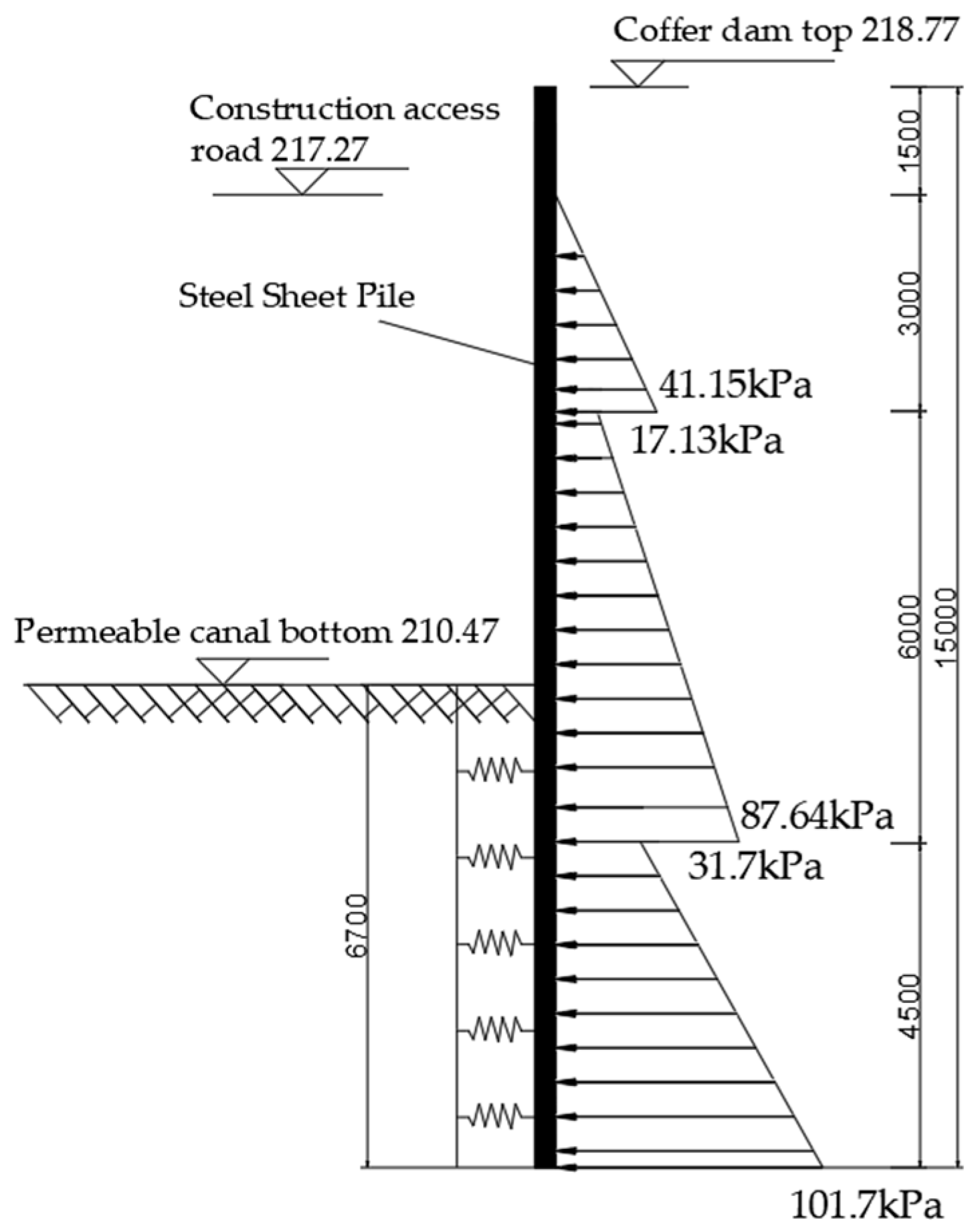
By substituting the relevant stratigraphic parameters of the project into Equations (1) to (5), the calculated force distribution on the steel sheet pile of the water intake infiltration channel is shown in Figure 4.

3.3. Calculation Results and Analysis

The stress characteristics of the supporting structure after the completion of the infiltration channel cofferdam construction are shown in Figure 5. The figure illustrates that the stress in the upper part of the steel sheet pile cofferdam is relatively small, while a significant increase in stress is observed in the central region, particularly within the depth range of 5.5 to 8.0 m. The corners of the foundation pit experience higher stress levels than the sides due to the effect of the stress concentration. The maximum stress value in the steel sheet piles reaches 64.3 MPa.
At the same time, the stress in the three layers of internal supports increases progressively from top to bottom. Notably, stress concentration is observed at the connection points between the internal supports and the surrounding girders. The maximum stress in the internal supports reaches 87.2 MPa.
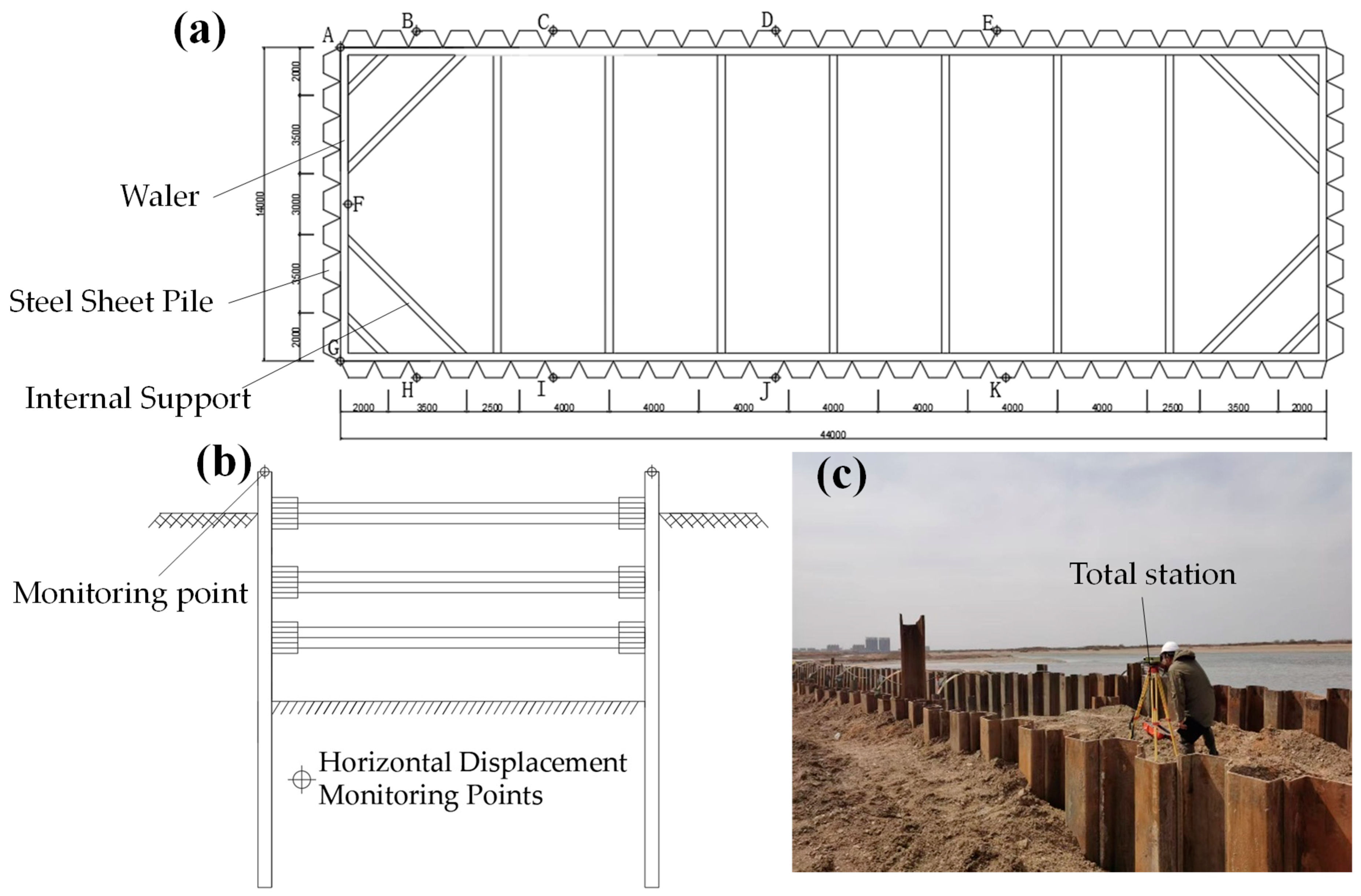
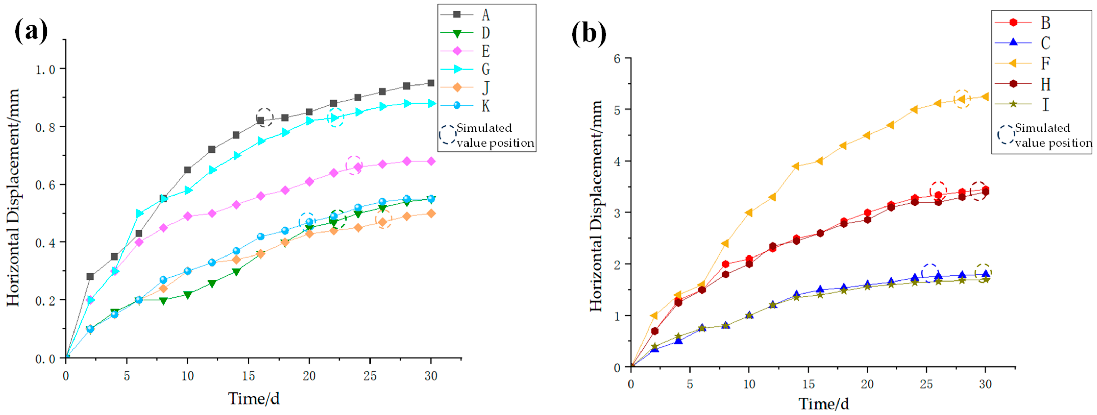
The displacement characteristics of the steel sheet pile cofferdam during the construction of the water intake infiltration channel are shown in Figure 6 (with pile numbers indicated in Figure 7). The overall structural displacement is primarily concentrated in the middle and along the sides, where the displacement values are larger, represented as prominent yellow and red areas. The maximum displacement reaches 6.96 mm (red area), indicating significant deformation. In contrast, the bottom of the steel sheet pile and areas with internal supports show smaller displacements, represented by green and blue regions, with displacements of less than 1 mm, indicating better structural stability. As shown in Figure 6b, the F pile (indicated by the yellow triangle) has the largest displacement, exceeding 6 mm, which is much higher than that of the other piles. This region is located at the narrow edge of the cofferdam, where the forces are complex. The pile is subjected to biaxial soil pressure, and the inclined bracing structure suffers from insufficient stiffness and uneven force transmission. The displacement of the B pile decreases gradually within the 0 to 6.5 m depth range due to the lack of horizontal support.

3.4. On-Site Monitoring

During the construction of the infiltration channel cofferdam, the deformation characteristics of the steel sheet piles were comprehensively monitored. This paper analyzes the monitoring results of 11 horizontal displacement monitoring points at the top of the steel sheet piles. Points A to E and H to K are located on the long side of the water intake project and are symmetrically distributed, while Point F is located at the center of the short side of the water intake project, as shown in Figure 7. The horizontal displacement monitoring at the top of the steel sheet piles was conducted using a Leica TS30 total station (Nanjing Maibang Instrument Technology Co., Ltd., Nanjing, China), with a measurement accuracy of 0.1 mm. Monitoring was conducted once daily during the excavation of the infiltration channel, with a continuous monitoring period of 30 days. To control the impact of environmental interference, the groundwater level changes in the region were recorded simultaneously during the monitoring period. The data fluctuations were within a range of ±0.3 m. The trend of displacement growth in the monitoring data showed a weak correlation with the water level fluctuations, indicating that the primary source of deformation was soil unloading. The field monitoring data of the horizontal displacement at the top of the steel sheet piles during the cofferdam construction and its comparison with the numerical calculation results are shown in Figure 8.
As shown in Figure 8, the time evolution of the horizontal displacement at the top of the steel sheet piles during the excavation of the water intake infiltration channel shows a distinct two-phase characteristic. In the initial rapid deformation phase (0–7 days), all monitoring points experience rapid displacement growth, with daily displacement increments at the monitoring points reaching 0.5 to 0.8 mm. This phase of deformation is primarily caused by the instantaneous unloading of soil due to the excavation of the foundation pit, leading to a redistribution of effective stress in the soil. In the later stage of stabilization and convergence (after 7 days), the rate of displacement growth significantly slows down, indicating that the soil consolidation improves and the collaborative effect of the support system (steel sheet piles, supports, and surrounding girder) strengthens, with deformation tending to stabilize. In terms of spatial distribution, there is a significant difference in displacement values at different locations in the water intake excavation. The peak displacement occurs at the side span center (Point F), with a maximum value of 5.3 mm. The next highest displacements are found at the corner near the right-angle areas (Points B and H), with peak displacements reaching 3.4 to 3.5 mm. Meanwhile, the displacements at the center of the long span (Points J, K, D, and E) and at the right-angle corner regions (Points A and G) remain relatively small, with peak values ≤ 1.9 mm. The numerical simulation results show good statistical consistency with the field monitoring data, with the differences falling within reasonable ranges.
The mechanism analysis of the spatial displacement differences described above reveals the following insights: The high displacement at Point F (with a peak value of about 5.3 mm) is primarily due to its location in the center of the side span, where it experiences a significant cantilever effect. Additionally, the combined lateral soil pressures on both sides contribute to the bending moment and deformation at this point, resulting in the maximum displacement at this location. The high displacement at Points B and H is caused by the relatively weak three-dimensional constraint conditions at the right-angle corner regions (θ = 90°). The insufficient coupling of the boundary effects on the adjacent sides leads to stress concentration in these areas, making them more prone to large deformations. Importantly, the peak displacement regions (Points F, B, and H) correspond spatially to the areas of peak bending moments in the numerical simulation. These points are all located in weak areas of the support system, where there is either a lack of support or excessive spacing between supports, as shown in the monitoring layout diagram. This directly confirms that the local stiffness of the support system is severely inadequate. The lack of support or excessive spacing between supports is the primary controlling factor for the significant increase in displacement at these critical points, especially at Point F.

4. Key Sediment Control Technologies for the Water Intake Project

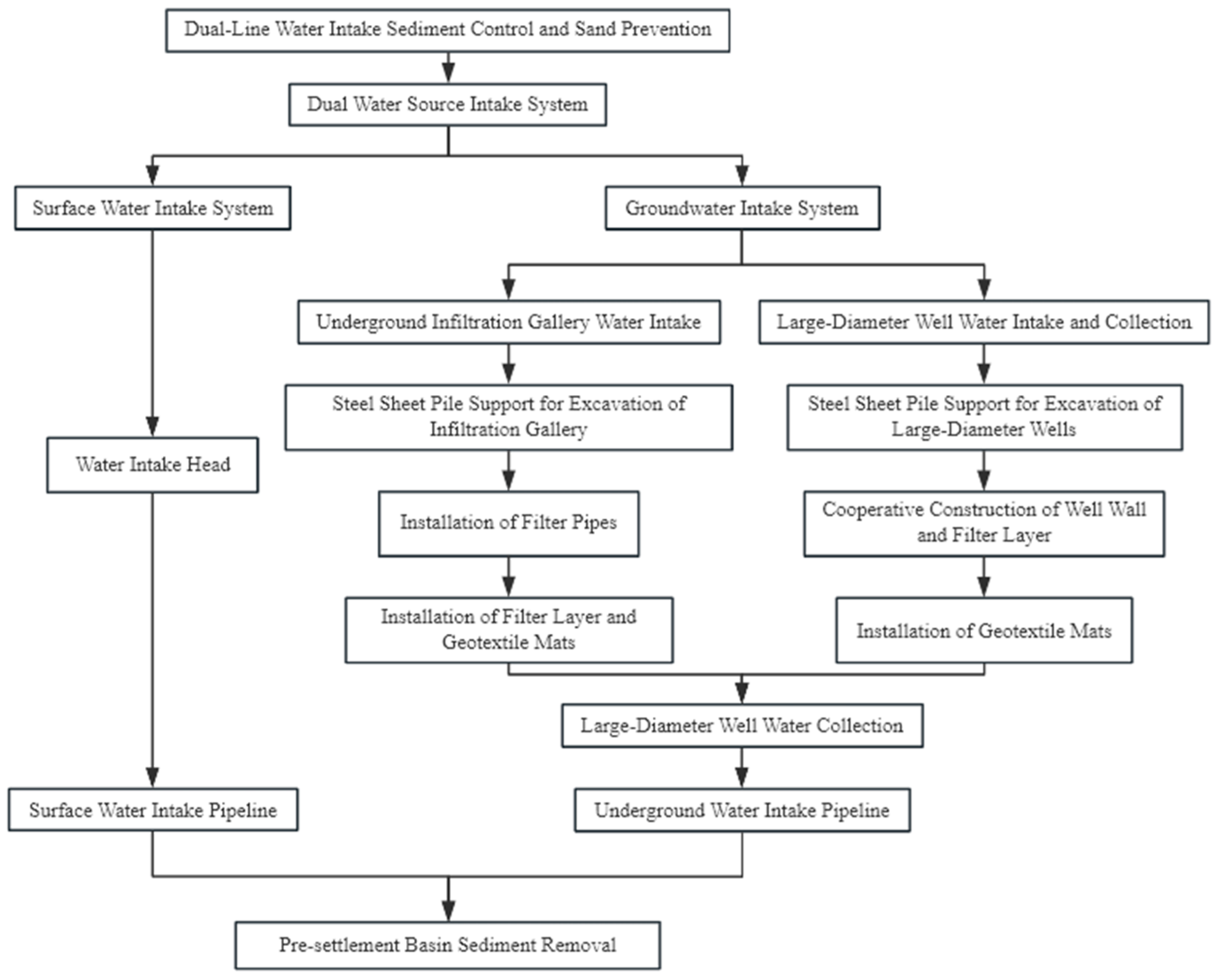
The Nenjiang Urban Water Intake Project implements a seasonal differentiated water extraction strategy through a dual independent intake system to control sediment at the source. The project adopts a composite reverse filtration layer with layered placement technology for the infiltration channel, using improved geotextile mats to resist river sand abrasion and water flow shear forces, significantly enhancing the anti-clogging performance and service life of the infiltration channel. Additionally, the project incorporates vertical reverse filtration layers in large wells, with layered wrapping and staggered horizontal intake holes, optimizing water flow uniformity and sediment filtration efficiency. The integrated technology system for the entire process is shown in Figure 9.

4.1. Sediment Control and Sand Settlement-Guided Dual-Line Water Intake Process

The Nenjiang Urban Water Supply Project innovatively establishes a “dual water source–dual pipeline–combined pumping station” water intake system (see Table 3, Figure 10). This system operates through the independent and coordinated switching between the surface water intake system (main source during the wet season) and the underground infiltration channel system (supplemental source during the dry season), achieving a seasonal differentiated water intake strategy. This system effectively responds to hydrological fluctuations and enhances the emergency water supply capability. The surface water source provides an abundant water supply but has a high sediment content, with turbidity significantly increasing during flood periods, thereby raising treatment costs. On the other hand, the groundwater source offers stable water quality but limited volume, with its infiltration channel water intake mode playing a key supplementary role during dry periods. The complementary characteristics of these two sources form the foundation for the operation of the dual system.
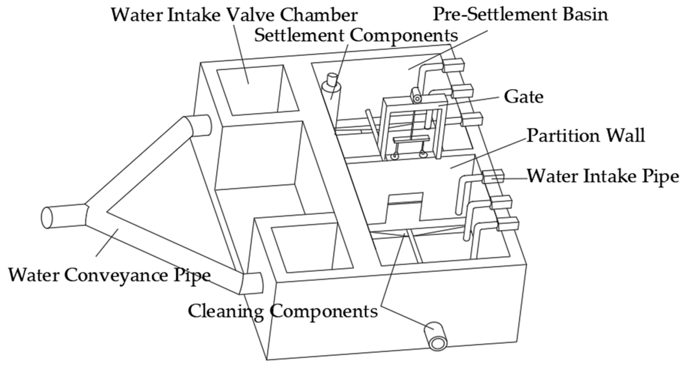
In response to the issue of sediment removal and water stoppage caused by the single intake in traditional pre-sedimentation tanks, a dual-pump rear pre-sedimentation tank structure has been developed (Figure 11). This design uses a parallel dual-tank configuration, where a conduit diverter is employed to ensure uniform water flow distribution. Each tank’s inlet and outlet are independently controlled by valves, and sluice gate components are set up to isolate the tank during maintenance periods. This system ensures the continuous operation of water treatment processes while improving system reliability.

4.2. Key Construction Technologies for Layered Placement of Composite Reverse Filtration Layers in Infiltration Channel Water Intake

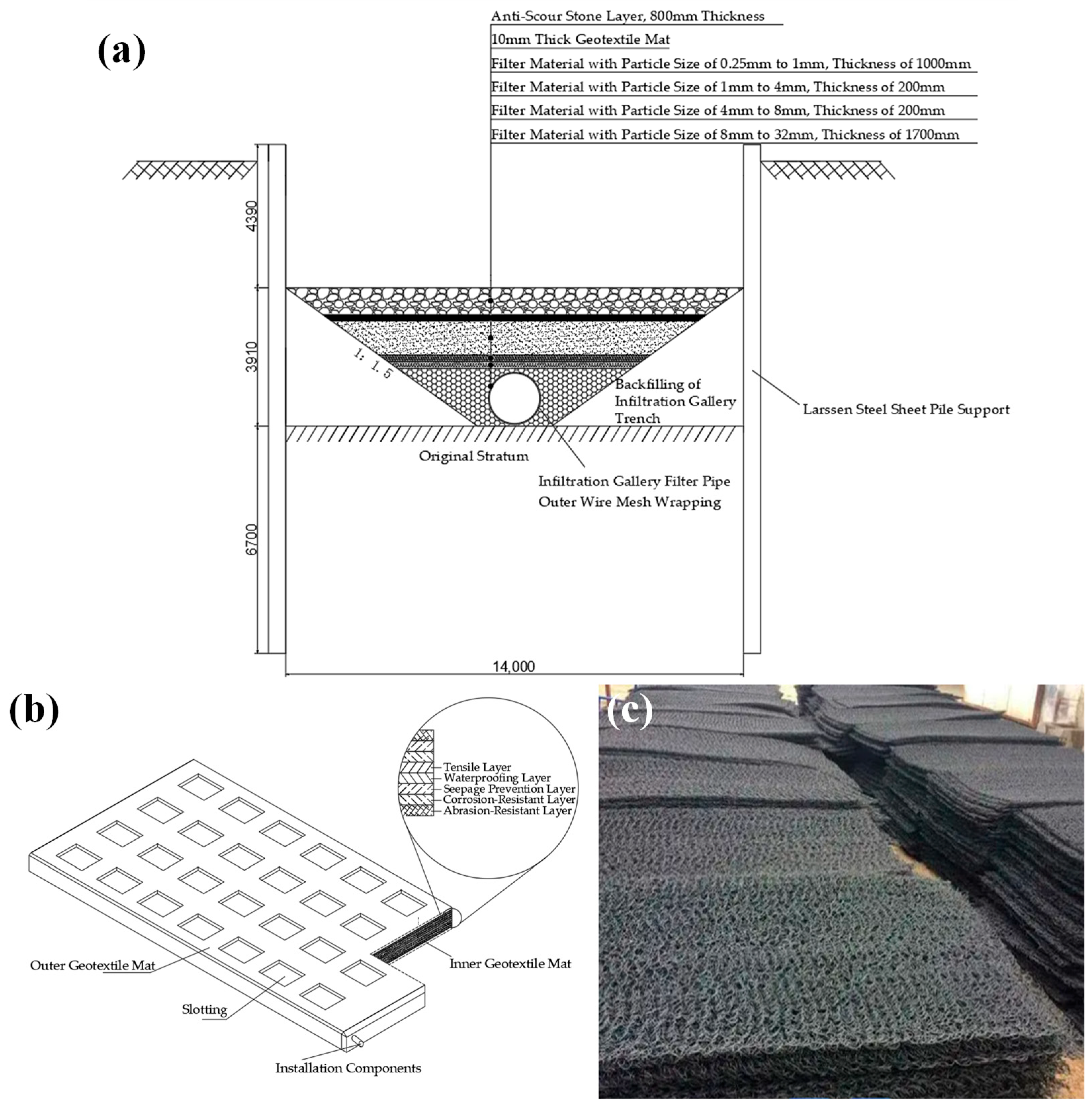
The infiltration channel trench is constructed using a steel sheet pile cofferdam, and the collection pipe is made of K12-grade socketed ductile iron pipe (DN1200 mm). The upper half of the pipe features a flower-shaped distribution of intake holes along its circumference. The external part of the collection pipe is fitted with a four-layer graded filtration material system (Figure 12a), which is arranged as follows from bottom to top: a coarse-grain crushed stone layer, a medium-grain crushed stone transition layer, a fine-grain crushed stone filtration layer, and a fine sand layer. An additional layer of steel wire mesh anti-scour stone is added to the outermost part, followed by a fine sand protection layer. An improved geotextile mat is placed between these layers to resist water flow erosion. The improved geotextile mat uses a composite protective structure (Figure 12b,c): the outer layer consists of tensile, waterproof, impermeable, anti-corrosion, and wear-resistant layers, providing a high-pressure and impact-resistant barrier. The inner layer is composed of a random fiber mesh and dual tensile layers to form a highly porous permeable structure, balancing impact resistance and permeability efficiency. The inner and outer layers are connected using snap-fit components, forming a synergistic protection system (key technical parameters are listed in Table 4 and Table 5).

4.3. Key Construction Technologies for the Collaborative Construction of the Infiltration Filter Layer and Well Casing Structure of the Large Well Water Intake Structure

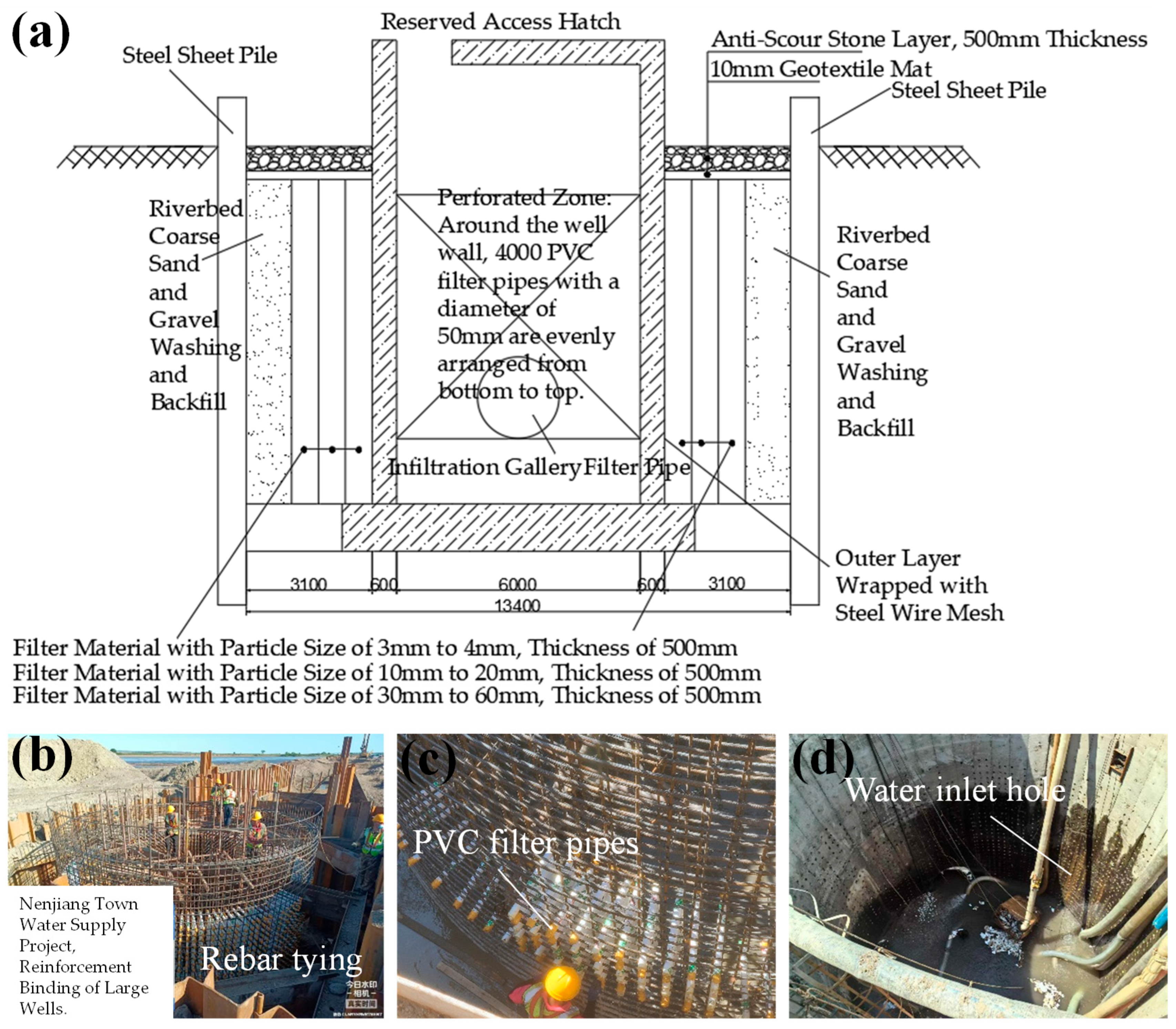
The Nenjiang Urban Water Supply Project includes four circular large-diameter wells, each with a depth of 10.0 m and a diameter of 6.0 m. The water intake construction for the large wells uses the large trenching method with a collaborative construction process. This method simultaneously constructs the well casing structure, intake hole array, and reverse filtration layer system (Figure 13a), ensuring the efficiency of water collection and structural stability. During the well casing reinforcement process, a matrix of PVC filter pipes is installed around the entire circumference of the well casing (Figure 13b–d) to ensure the even distribution of the intake channels. The reverse filtration layer is filled with graded materials, including pebbles, gravel, and coarse sand, from the inside to the outside. The outermost layer is reinforced with a geotextile mat, forming a comprehensive protective system to ensure the integrated and collaborative function of the reverse filtration layer and well casing.

4.4. Sediment Control and Sand Settlement Effectiveness in Water Intake Projects

To verify the sediment control effectiveness, simultaneous sampling was conducted at the water intake head (surface water) and the infiltration channel outlet (pre-sedimentation tank inlet). Each water sample was collected from different locations, ensuring spatial representativeness. The sampling frequency at each location was once per day. The sample collection work was carried out alternately by two operators to minimize human error. A comparison test of sand content was performed using the drying and weighing method:
Step 1: Clean and dry three beakers to a constant weight (at 105 °C ± 2 °C), then cool and weigh the initial mass (accuracy to 0.001 g);
Step 2: Take 50 mL of each well-mixed river water sample, dry it to a constant weight, and then weigh the total mass;
Step 3: Treat 50 mL of the infiltration channel water sample in the same manner (experimental setup shown in Figure 14).
The results (Table 6) show that the average sand content of the infiltration channel water sample is reduced by 75% compared to the surface water sample, confirming that the infiltration channel system, through optimized filter material grading and the retention effect of geotextile mats, significantly improves water quality stability. The full-process sediment control technology meets the engineering water quality control requirements (sand content ≤ 100 mg/L).

5. Conclusions

(1)
The stress peak of the FSP-IV steel sheet pile supporting structure in the excavation of the infiltration channel foundation pit (64.3 MPa) is concentrated at the center of the pit at depths of 5.5–8.0 m. The maximum horizontal displacement (6.96 mm) occurs at the middle of the side span at the F pile. The internal support stress increases with depth, reaching 87.2 MPa at the bottom, with significant stress concentration at the connection between the surrounding girder and the piles. The lack of support or excessive spacing between supports leads to insufficient local stiffness at the side span center (Point F, with a displacement of 5.3 mm) and the right-angle region (Points B/H), which is the main cause of displacement exceeding the limit. Field monitoring verified the reliability of the numerical model.
(2)
The sediment control and sand settlement integrated system for the water intake infiltration channel achieves a 75% reduction in sand content and a significant decrease in standard deviation through the dual-line water intake method, the layered placement of reverse filtration layers in the infiltration channel, and the collaborative construction technology of the intake holes and reverse filtration layers. This system ensures both water quality stability and continuous water supply, forming a systematic technological solution for water intake from rivers with a high sediment content.

Author Contributions

Conceptualization, Z.Z. and L.W. (Liang Wu); Data curation, R.L. and F.C.; Methodology, Z.Z. and R.L.; Formal analysis, Z.Z. and L.W. (Liang Wu); Investigation, L.W. (Lin Wei) and F.C.; Writing—original draft, Z.Z. and L.W. (Liang Wu); Writing—review and editing, Z.Z. and R.L.; Supervision, Z.Z. and L.W. (Liang Wu); Project administration, Z.Z. and R.L.; Resources, Z.Z., R.L., and L.W. (Lin Wei); Supervision, Z.Z. and L.W. (Liang Wu); Validation, R.L. and L.W. (Lin Wei); Visualization, Z.Z. and R.L. All authors have read and agreed to the published version of the manuscript.

Funding

This study was funded by the Science and Technology Plan of Housing and Urban-Rural Construction in Anhui Province (2022-YF096), and Science and technology development project (HYB20250019, HYB20250012).

Data Availability Statement

Data is contained within the article.

Conflicts of Interest

Author Rui Luo was employed by the company The First Engineering Co., Ltd., CTCE Group. Author Lin Wei was employed by the company Chengji Railway Engineering Technology Limited Company. The remaining authors declare that the research was conducted in the absence of any commercial or financial relationships that could be construed as a potential conflict of interest.

References

  1. Yang, Y.; Liu, W.; Hu, A.; Li, F.; Yang, Z. Application of Steel Sheet Pile in Deep Foundation Pit Support of Collapsible Loess Regions. Earth Environ. Sci. 2020, 474, 02088. [Google Scholar] [CrossRef]
  2. Marazuela, M.; Garcia, A.; Santamarta, J.C.; Gasco, S.; Cruz, N.; Hofmann, T. Stormwater management in urban areas using dry gallery infiltration systems. Sci. Total Environ. 2022, 823, 153705. [Google Scholar] [CrossRef] [PubMed]
  3. Anderson, E.I. Yield Equations for Bed-Mounted Infiltration Galleries. J. Irrig. Drain. Eng. 2023, 149, 060230031-6. [Google Scholar] [CrossRef]
  4. Lewis, J.R.; Farr, S.J. Design and construction of a sheet pile earth retention system in soft clays. IFCEE 2015 2015, 1536–1549. [Google Scholar] [CrossRef]
  5. Zhu, M.; Ebrahimi, A.; Viswanath, M.; Brussel, L.; Beech, J. Design and monitoring of a sheet pile wall installed in soft industrial waste. IFCEE 2015 2015, 627–635. [Google Scholar] [CrossRef]
  6. Wang, J.; Xiang, H.; Yan, J. Numerical simulation of steel sheet pile support structures in foundation pit excavation. Int. J. Geomech. 2019, 19, 05019002. [Google Scholar] [CrossRef]
  7. Ouyang, w.; Yang, Y.; Wan, J.; Liu, S. Second-order analysis of steel sheet piles by pile element considering nonlinear soil-structure interactions. Adv. Steel Constr. 2020, 16, 354–362. [Google Scholar] [CrossRef]
  8. Veylon, G.; Stoltz, G.; Mériaux, P.; Faure, Y.; Touze-Foltz, N. Performance of geotextile filters after 18 years’ service in drainage trenches. Geotext. Geomembr. 2016, 44, 515–533. [Google Scholar] [CrossRef]
  9. Erat, B.; Barbaros, E.; Taştan, K. Experimental and Numerical Investigation on Flow and Scour Upstream of Pipe Intake Structures. Arab. J. Sci. Eng. 2024, 49, 5973–5987. [Google Scholar] [CrossRef]
  10. Chowdhury, S.S.; Deb, K.; Sengupta, A. Estimation of design parameters for braced excavation: Numerical study. Int. J. Geomech. 2013, 13, 234–247. [Google Scholar] [CrossRef]
  11. Azzam, W.R.; Elwakil, A.Z. Performance of axially loaded-piled retaining wall: Experimental and numerical analysis. Int. J. Geomech. 2017, 17, 04016049. [Google Scholar] [CrossRef]
  12. Denisov, G.V.; Lalin, V.V.; Abramov, D.S. Preservation of Lock Joints in Steel Sheet Piling During Vibratory Driving. Soil Mech. Found. Eng. 2014, 51, 29–35. [Google Scholar] [CrossRef]
  13. Wang, J.; Jiang, Z.; Li, F.; Chen, W. The prediction of water level based on support vector machine under construction condition of steel sheet pile cofferdam. Concurr. Comput. Pract. Exp. 2021, 33, e6003. [Google Scholar] [CrossRef]
  14. Athanasopoulos, G.A.; Vlachakis, V.S.; Pelekis, P.C. Installation and performance of a steel sheet pile wall for supporting an excavation in urban environment. Geotech. Spec. Publ. 2011, 3370–3380. [Google Scholar] [CrossRef]
  15. Lee, F.; Hong, S.; Gu, Q.; Zhao, P. Application of large three-dimensional finite-element analyses to practical problems. Int. J. Geomech. 2011, 11, 529–539. [Google Scholar] [CrossRef]
  16. Zhou, X.; Liu, C.; Qian, Y. Design of very long steel sheet pile cofferdam for deep water foundation and key construction techniques. World Bridge 2020, 48, 20–24. Available online: https://kns.cnki.net/kcms2/article/abstract?v=4OORb77KhuLGF1cpZsZbp69TOcraROLxoDMVVq5gLNK2l15UBlQAzH29ghSRi7gcB3KLLzdpEOhG2Ttc2L5b1tBJ0uYLhrlC1FrHxZrGRjV_nNvHBCDzcwEIPswp7RAjzclMJN_PU3Q6jrxPNT4eXPsE_ESbT5VHSPADZEd4FijMkSkR3fobubK1CVMyqd0BNrTX9GJvtS4=&uniplatform=NZKPT&language=CHS (accessed on 19 June 2025). (In Chinese).
  17. Rad, M. Reliability based analysis and optimum design of laterally loaded piles. Period. Polytech. Civ. Eng. 2017, 61, 491–497. [Google Scholar] [CrossRef]
  18. Lv, G.; Liu, Z.; Yu, X.; Zhang, F.; Meng, Q.; Hu, X. Numerical modeling and analysis of steel sheet pile cofferdams, considering the construction sequence. Buildings 2025, 15, 407. [Google Scholar] [CrossRef]
  19. Chen, Y.; Wang, H.; Zhang, F.; Meng, Q.; Liu, Z. Study on the calculation model of mutually embedded displacement between miscellaneous fill and soft soil. Bull. Eng. Geol. Environ. 2024, 83, 348. [Google Scholar] [CrossRef]
  20. Huang, Y.; Fei, Z.; Kang, A.; Zhang, D.; Jin, K. Research on Effective Embedded Depth of Bottomless Steel Sheet Pile Cofferdam in Rock. Bridge Constr. 2023, 53, 103–110. (In Chinese) [Google Scholar] [CrossRef]
  21. Xue, R.; Bie, S.; Guo, L.; Zhang, P. Stability analysis for cofferdams of pile wall frame structures. KSCE J. Civ. Eng. 2019, 23, 4010–4021. [Google Scholar] [CrossRef]
  22. Xu, C.; Tian, J.; Wang, G.; Lian, H.; Wang, R.; Hu, X. Numerical Analysis of Water–Sediment Flow Fields within the Intake Structure of Pumping Station under Different Hydraulic Conditions. Water 2024, 16, 779. [Google Scholar] [CrossRef]
  23. Sesler, K.; Missimer, T.M. Technical feasibility of using seabed galleries for seawater RO facility intakes and pretreatment: Om al misk island site, red sea, saudi Arabia. In Proceedings of the AMTA/AWWA Membrane Technology Conference and Exposition, San Antonio, TX, USA, 25–28 February 2013; pp. 484–496. [Google Scholar]
  24. Zheng, W.; Lichwa, J.; D’Alessio, M.; Ray, C. Fate and transport of TNT, RDX, and HMX in streambed sediments: Implications for riverbank filtration. Chemosphere 2009, 76, 1167–1177. [Google Scholar] [CrossRef] [PubMed]
  25. Taylor, J.; Geogre, C. Geology and ground water of the azapa valley, province of tarapaca, Chile. Econ. Geol. 1949, 44, 40–62. [Google Scholar] [CrossRef]
  26. Amin, M.I.; Qazi, R.; Downing, T.E. Efficiency of Infiltration Galleries as a Source of Water in Arid Lands. Water Int. 1983, 8, 158–165. [Google Scholar] [CrossRef]
  27. Xu, C.; Du, C.; Yang, Y.; Shen, P.; Li, M. Long-term permeability tests on clogging and permeability of nonwoven geotextile filtering silty clay. J. Text. Inst. 2022, 114, 1704–1715. [Google Scholar] [CrossRef]
  28. Michell, F.; Ettema, R.; Muste, M. Case Study: Sediment Control at Water Intake for Large Thermal-Power Station on a Small River. J. Hydraul. Eng. 2006, 132, 440–449. [Google Scholar] [CrossRef]
  29. GB 18306-2015; Seismic ground motion parameters zonation map of China. Institute of Geophysics, China Earthquake Administration: Beijing, China, 2015. Available online: https://www.gb18306.net (accessed on 6 May 2025).
  30. Tan, H. Design and Construction of Steel Sheet Pile Cofferdam for Deep Water Piers of Long Bridge. Highway 2024, 69, 153–157. [Google Scholar]
  31. Yang, S.; Liu, X.; Feng, Y.; Wang, Z.; Liu, Z. Research on Steel Sheet Pile Cofferdam Technology in Deep Water Dense Sandstone Strata. Highway 2021, 66, 184–188. Available online: https://link.cnki.net/urlid/11.1668.U.20210111.0919.066 (accessed on 19 June 2025).
  32. Li, H. Comparison of Structural Performance between Deep Water Reverse and Forward Construction Methods for Steel Sheet Pile Cofferdam. China Railw. 2022, 11, 55–62. [Google Scholar] [CrossRef]
  33. Huang, K.; Feng, R. Deep pit foundation steel sheet pile supporting scheme of the 274# pile cap for super large bridge over the coastal expressway and the North Jiangsu irrigation canal. In Proceedings of the 5th International Conference on Material and Manufacturing Technology, Kuala Lumpur, Malaysia, 8–9 May 2014; Trans Tech Publications Ltd.: Kuala Lumpur, Malaysia, 2014; pp. 341–345. [Google Scholar] [CrossRef]
  34. JGJ120-2012; Building Foundation pit Support Design Regulations. China Academy of Building Research: Beijing, China, 2012. Available online: https://www.mohurd.gov.cn/gongkai/zc/wjk/art/2012/art_17339_210547.html (accessed on 11 May 2025.).
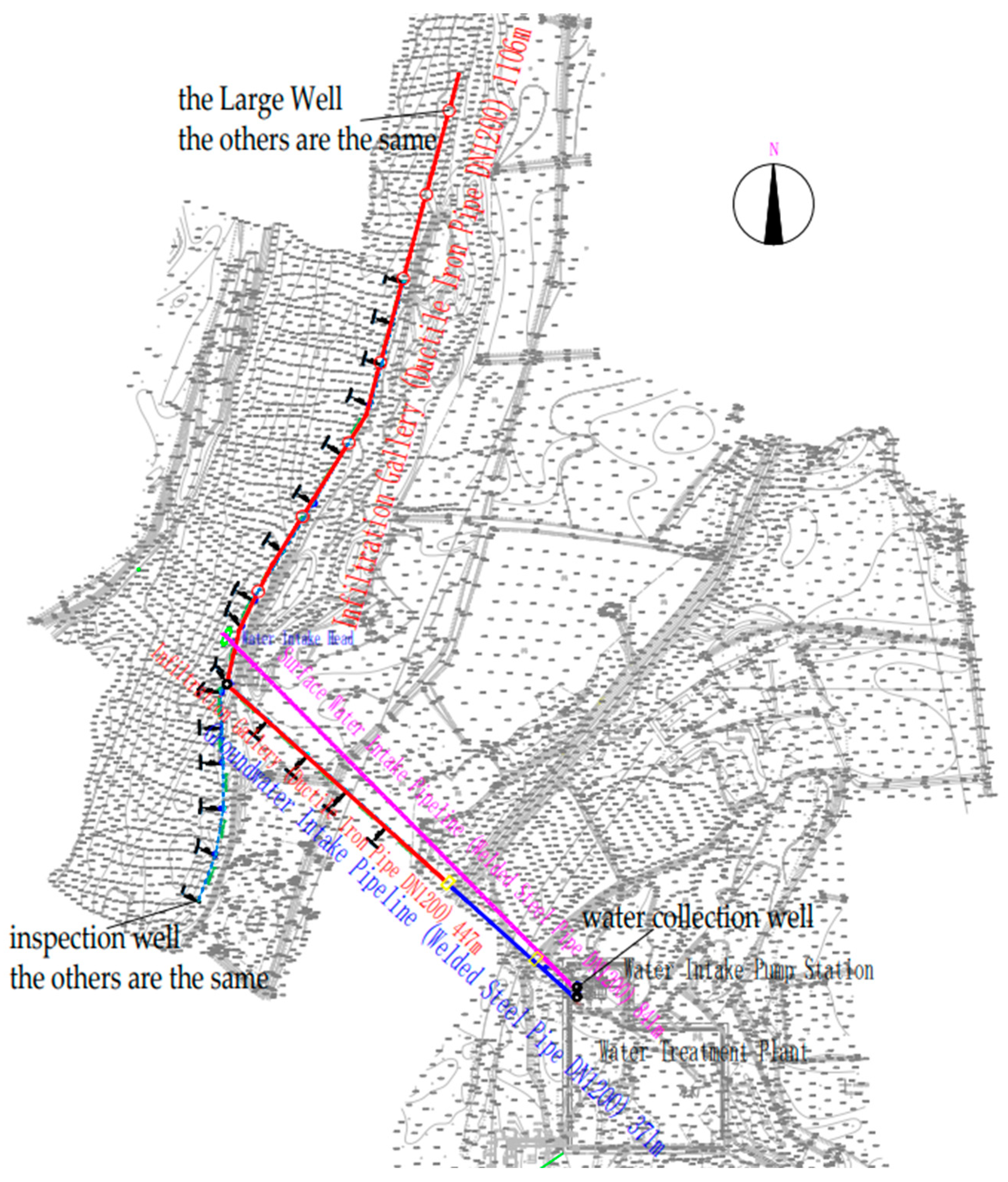
Figure 1. Nenjiang Urban Water Intake Project.
Buildings 15 02610 g001
Figure 2. Steel sheet pile cofferdam for water intake infiltration gallery: (a) aerial view of the construction site; (b) infiltration gallery support system; and (c) cross-sectional view of the infiltration gallery support structure.
Buildings 15 02610 g002
Figure 3. Finite element model of the steel sheet pile cofferdam.
Buildings 15 02610 g003
Figure 4. Schematic diagram of the steel sheet pile cofferdam stress analysis.
Buildings 15 02610 g004
Figure 5. Stress distribution of steel sheet piles and internal bracing (MPa): (a) stress diagram of steel sheet piles; (b) stress diagram of internal support.
Buildings 15 02610 g005
Figure 6. Displacement diagram of steel sheet piles in the cofferdam construction for the water intake project (mm): (a) overall displacement contour map; (b) pile displacement.
Buildings 15 02610 g006
Figure 7. Monitoring of horizontal displacement at the top of steel sheet piles during cofferdam construction for the water intake project: (a) plan view of horizontal displacement monitoring point layout; (b) sectional view of horizontal displacement monitoring point layout; and (c) monitoring site.
Buildings 15 02610 g007
Figure 8. Horizontal displacement at the top of steel sheet piles during cofferdam construction for the water intake project: (a) the top of A, D, E, G, J, K sheet piles is horizontally displaced; (b) the top of B, C, F, H, I sheet piles is horizontally displaced.
Buildings 15 02610 g008
Figure 9. Sediment control and sand prevention process flow for the riverbank water intake project.
Buildings 15 02610 g009
Figure 10. Water intake and supply process flow diagram.
Buildings 15 02610 g010
Figure 11. Double water intake pump pre-settlement basin structure.
Buildings 15 02610 g011
Figure 12. Water intake infiltration gallery structure diagram: (a) infiltration gallery cross-section; (b) filter pipe; and (c) inner geotextile mat.
Buildings 15 02610 g012
Figure 13. Large well water intake structure: (a) cross-section diagram of large well water intake structure; (b) rebar binding; (c) filter pipe installation; and (d) well wall structure.
Buildings 15 02610 g013
Figure 14. Sand content experiment of water quality: (a) beaker net weight; (b) water sample collection; and (c) residue weighing.
Buildings 15 02610 g014
Table 1. Geological parameters.
Stratum TypeDensity (kN/m3)Cohesion (kPa)Internal Friction Angle (°)Elastic Modulus (MPa)Poisson’s Ratio
Mixed Fill Soil10.000400.3
Gravel18825800.26
Sandstone20.0202020000.22
Table 2. Stiffness of soil springs at various locations.
Depth of Calculation Point/(m)m/(MN/m4)Design Width of Sheet Pile, b/(m)Design Height of Sheet Pile, h/(m)Stage I Soil Spring Stiffness, k1 (kN/m)Stage II Soil Spring Stiffness, k2 (kN/m)Stage III Soil Spring Stiffness, k3 (kN/m)
410,4000.20.5000
4.510,4000.20.552000
510,8000.20.5106000
5.510,8000.20.5160000
610,8000.20.5214000
6.510,8000.20.526805400
710,8000.20.5322010800
7.510,8000.20.5376016200
810,8000.20.5430021600
8.510,8000.20.548402700216
910,8000.20.553803240756
9.510,8000.20.5592037801296
1010,8000.20.5646043201836
10.510,8000.20.5700048602376
1180000.20.5740052602776
11.580000.20.5780056603176
1280000.20.5820060603576
12.580000.20.5860064603976
1380000.20.5900068604376
13.580000.20.5940072604776
1480000.20.5980076605176
14.580000.20.510,20080605576
1580000.20.510,60084605976
Table 3. Composition and characteristics of the dual water intake process system.
System ComponentSystem Characteristics
Surface Water SystemDirect water intake from the Nenjiang River during the wet season, equipped with intake head and intake pipeline.
Groundwater SystemDuring the dry season, groundwater is collected through infiltration galleries in the floodplain and transported to the pump station.
Intake Pump StationCombined pump station for both surface water and groundwater, sharing pressurization equipment and water transport systems.
Water Transportation PipelineSurface water and groundwater pipelines are laid in parallel, converging into the water treatment plant.
Table 4. Technical specifications of improved geotextile mat material.
Geotextile MatTensile Strength (Longitudinal)Tensile Strength (Transverse)Abrasion ResistancePermeability Coefficient (Inner Layer)Porosity
Traditional geotextile mat16 kN/m16 kN/m420 cycles1.0× 10−2 cm/s≥60%
New-generation geotextile mat≥25 kN/m≥20 kN/m≥500 cycles1.2 × 10−2 cm/s≥75%
Table 5. Comparison of filtration performance test results.
Geotextile MatInitial Permeability Coefficient (cm/s)24 h Permeability Coefficient Decrease RateClogging StatusMaterial Failure Conditions
Traditional geotextile mat1.0 × 10−242.7%YesSevere surface sedimentation
New-generation geotextile mat1.2 × 10−29.4%NoNo significant damage
Table 6. Test Results.
Water SampleSerial NumberSand ContentAverage ValueStandard DeviationRangeConfidence Interval (95%)
Intake head water sample10.0146 g0.0144 g0.00017320.0003[0.01397, 0.01483]
20.0143 g
30.0143 g
Pre-settlement pool water sample10.0038 g0.0036 g0.00015280.0003[0.00325, 0.00325]
20.0036 g
30.0035 g
Disclaimer/Publisher’s Note: The statements, opinions and data contained in all publications are solely those of the individual author(s) and contributor(s) and not of MDPI and/or the editor(s). MDPI and/or the editor(s) disclaim responsibility for any injury to people or property resulting from any ideas, methods, instructions or products referred to in the content.