Article

Enhancing Mechanical Properties of Three-Dimensional Cementitious Composites Through 3 mm Short Fibre Systems: Single and Hybrid Types

School of Civil Engineering and Architecture, East China Jiaotong University, Nanchang 330013, China
*
Author to whom correspondence should be addressed.
Buildings 2025, 15(14), 2519; https://doi.org/10.3390/buildings15142519
Submission received: 17 June 2025 / Revised: 10 July 2025 / Accepted: 12 July 2025 / Published: 18 July 2025
(This article belongs to the Special Issue Advanced Research on Cementitious Composites for Construction)

Abstract

Three-dimensionally printed cement-based composites emerge as a research hotspot in the fields of construction engineering in recent years. Current research primarily focuses on the reinforcement mechanisms of individually incorporated fibres, while a significant gap remains in the synergistic effects of hybrid fibre systems. This study investigates the effects of mono-doping (0.2 wt.% and 0.4 wt.% by the mass of the cement) and hybrid-doping (0.1 wt.% + 0.1 wt.% by the mass of the cement) with 3 mm polypropylene, basalt, and carbon fibres on the fresh-state properties and mechanical behaviours. Through quantitative characterisation of the flowability and mechanical performance of short-fibre-reinforced 3D-printed cementitious composites (SFR3DPC), coupled with comprehensive testing including digital image correlation, X-ray diffraction, and scanning electron microscopy, several key findings are obtained. The experimental results indicate that the addition of excess fibres reduces fluidity, which affects the mechanical performance and make the anisotropy of the composites more pronounced. While the single addition of 0.2 wt.% CF shows the most significant improvement in flexural and compressive strengths, the hybrid combination of 0.1 wt.% CF and 0.1 wt.% BF shows the greatest increase in interlayer bond strength by 26.7%. The complementary effect of the hybrid fibres contributes to the damage mode of the composites from brittle fracture to quasi-brittle behaviour at the physical level. These findings offer valuable insights into optimising the mechanical performance and improving defects of 3D-printed cementitious composites with short fibres.

Graphical Abstract

1. Introduction

Three-dimensional concrete printing technology is an innovative construction technique that integrates structural design and fabrication, eliminating the need for traditional formwork. Owing to its high-efficiency construction processes and modular production capabilities, it has attracted considerable attention in recent years [1,2,3]. Compared with conventional construction methods, this additive manufacturing approach, based on layer-by-layer deposition, offers notable advantages such as reduced material consumption, optimised design, shortened construction time, and enhanced sustainability [4,5,6,7]. Cement-based materials serve as excellent matrix components due to their ability to be printed without the use of formwork and their cost effectiveness. As a result, cementitious 3D printing technologies have seen increasing adoption in practical applications [8]. However, the intrinsic brittleness of these materials (marked by limited tensile strength and strain capacity [9]) necessitates material enhancement strategies to improve performance.
Fibre reinforcement has been widely adopted to mitigate challenges associated with brittle fracture behaviour, poor crack resistance, and limited control over crack propagation [10]. Appropriate fibre incorporation not only enhances compressive, flexural, and interlaminar bond strength but also alters the fracture mode from brittle to quasi-brittle, thereby significantly enhancing toughness and durability [11,12]. As a result, fibre reinforcement effectively enhances both the strength and overall mechanical behaviour of cementitious composites [13,14,15,16]. Commonly used fibres include steel [17,18], glass [19], basalt (BF) [20], polypropylene (PP) [21], jute [22], and carbon fibres (CF) [23,24], which improve mechanical performance by bridging cracks, thereby restricting their initiation and propagation. Although long fibres exhibit potential to enhance performance, their use in concrete reinforcement often yields suboptimal results due to fibre balling and inadequate dispersion. Bakhshi et al. have reported that fibres measuring 12–15 mm in length tend to clog 3D printer nozzles [25]. Wang et al. have demonstrated that 12 mm long fibres exert more adverse effects on workability compared to 6 mm short fibres [26]. Liu et al. have observed reduced fibre agglomeration in 1–3 mm fibres relative to their 5–7 mm counterparts [27]. In contrast, short fibres offer distinct advantages in minimising nozzle clogging, maintaining workability, and reducing fibre agglomeration [28].
Numerous studies have investigated various short fibre types for reinforcing cementitious materials. Studies have primarily focused on polypropylene (PP), basalt (BF), and carbon fibres (CF). PP fibres effectively mitigate early-age shrinkage cracking while enhancing plastic deformation capacity [29,30]. BF exhibits superior alkali resistance and high-temperature stability, making it effective in suppressing interlayer cracking [31,32,33]. CF offers exceptional strength and stiffness, substantially improving load-bearing capacity and fracture toughness [34]. Wang et al. examined the effects of PP fibres on mortar and the interfacial transition zone (ITZ), reporting 28-day flexural strength improvements of 9.6%, 15.0%, and 11.1%, along with corresponding splitting tensile strength increases of 9.5%, 21.9%, and 10.7% (at 0.2%, 0.4%, and 0.6% volumetric PP fibre contents, respectively) [35]. Wu et al. documented flexural strength enhancements of 4.15%, 20.61%, 28.70%, and 46.85% with BF volume fractions increasing from 0.125% to 0.5% [36]. Chen et al. investigated the effects of CF content on tensile behaviour, observing tensile strength increases of 26.3%, 15.6%, and 13.5% for each 0.1% increment in CF content, up to 0.3% [37].
Existing studies have primarily focused on single-fibre reinforcement mechanisms for enhancing hardened properties, leaving notable knowledge gaps concerning the synergistic effects of hybrid fibre systems and comparisons between the two. Single-fibre types exhibit inherent performance limitations [38]. PP fibres possess a relatively low elastic modulus and tensile strength [39]; BF fibres demonstrate inadequate alkali resistance [40]; CFRP-strengthened reinforced concrete structures exhibit interfacial bonding deficiencies [41]. The incorporation of hybrid fibres offers a promising approach by combining materials with complementary mechanical properties to achieve improved strength–ductility performance.
Extensive experimental investigations have validated the rationality of utilising the fibre dosages for this study. Song et al. believe that the optimal content of steel fibres and MWCNTs in multifunctional UHPFRC should be 2 vol.% and 0.2 wt.% [42]. Experimental studies by Piao et al. demonstrated that an incorporation of 0.3–0.4 wt.% carbon fibres (CFs) achieves an optimal equilibrium between mechanical strength and thermoelectric performance [43]. Therefore, 0.2wt.% and 0.4wt.% were chosen as the fibre incorporation contents for investigation.
This study innovatively employs a “fibre substitution” strategy to comparatively assess two doping methodologies: 0.1 wt.% + 0.1 wt.% (by the mass of the cement) and 0.2 wt.% (by the mass of the cement) standalone inclusion. The performance evaluation specifically contrasts hybrid and single-fibre doping effects on the mechanical properties of cementitious composites. Through intergroup and directional comparisons, the intrinsic correlation between fibre reinforcement mechanisms and structural anisotropy was elucidated through microstructural analysis, providing both theoretical support and practical guidance for the development of high-performance 3D-printed construction composites.

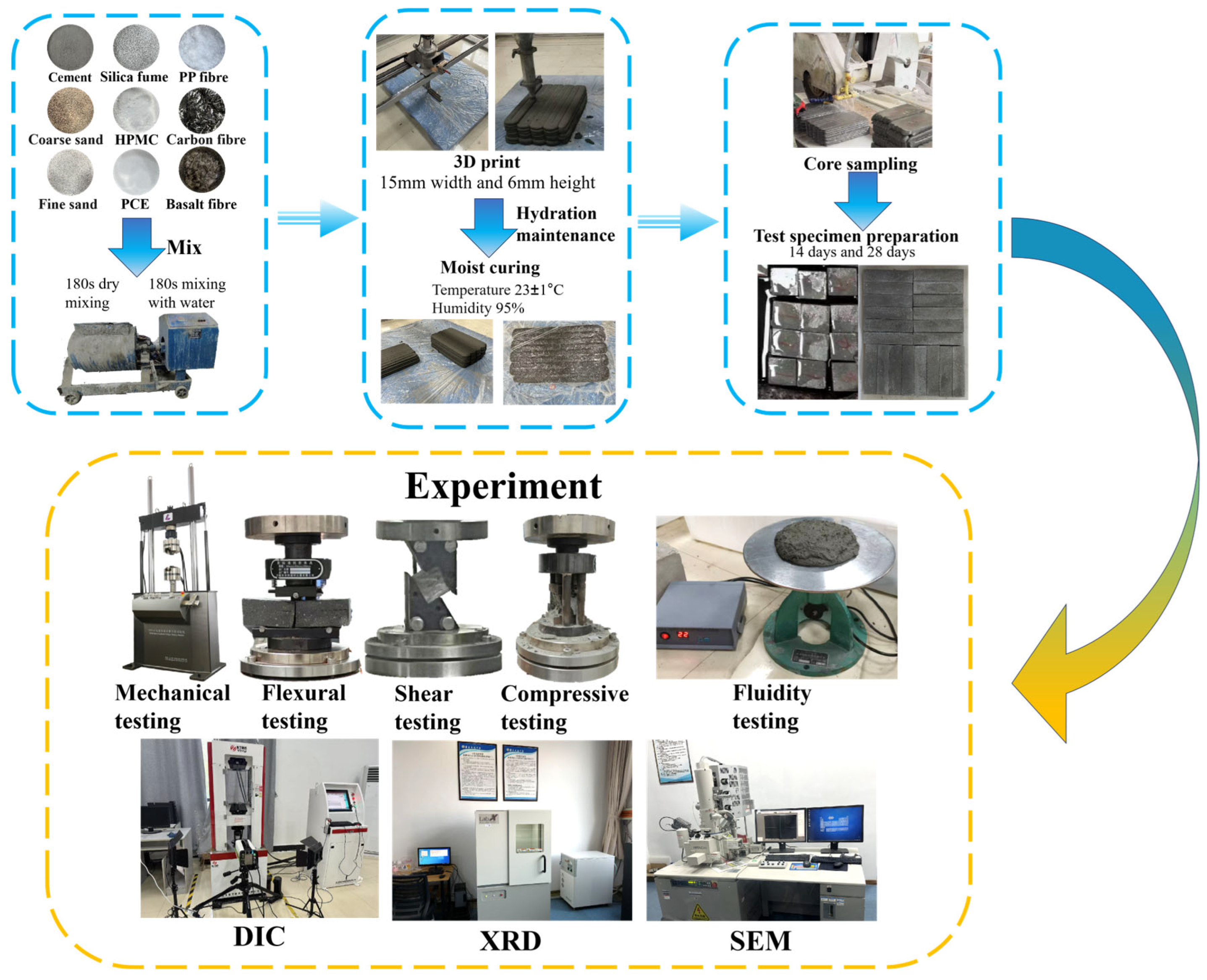
2. Experimental Program
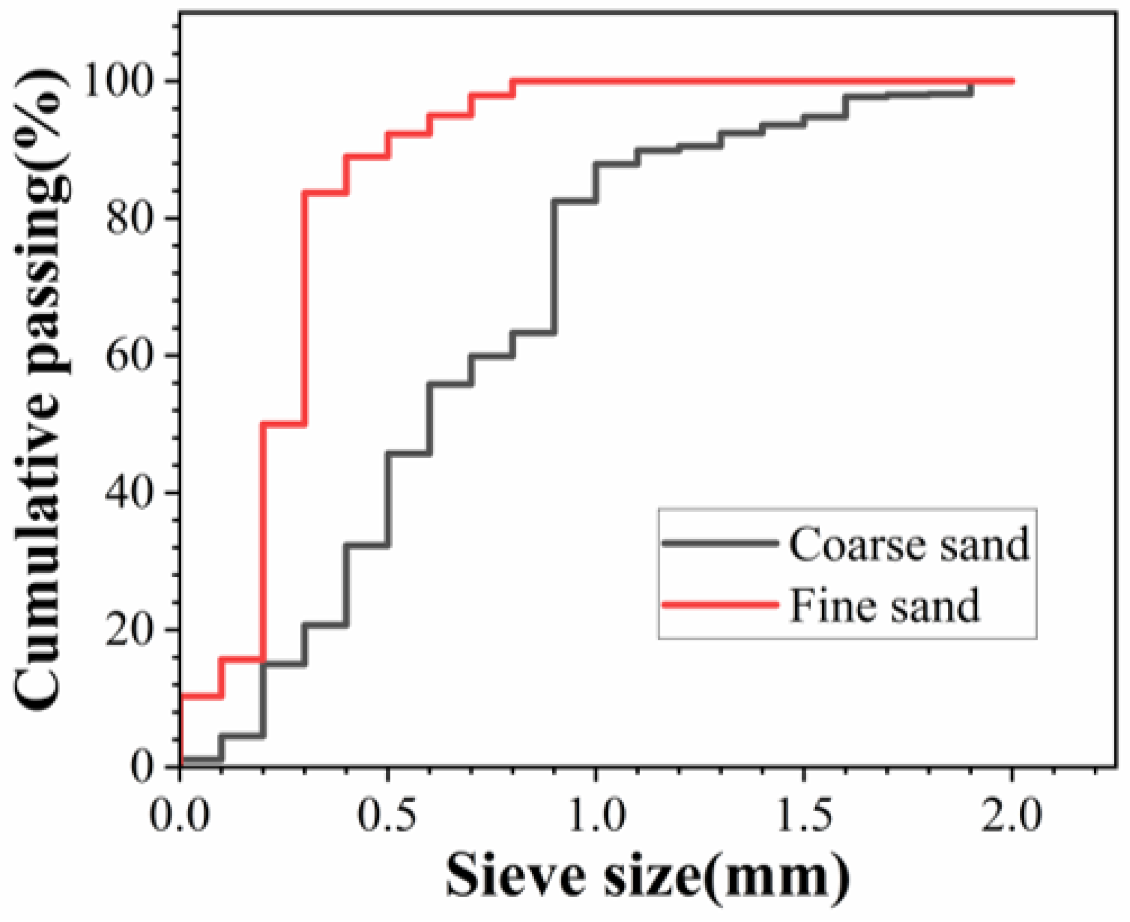
2.1. Materials

The cement employed in this study was Conch P.O 42.5-grade ordinary Portland cement, with a specific surface area of 335 m2/kg and a density of 3.06 g/cm3. The silica fume used was Type 98, with a specific surface area of 22,100 m2/kg and a density of 0.41 g/cm3. supplied by Henan Yixiang New Material Co., Ltd., Zhoukou, China. Their detailed properties are listed in Table 1. Natural river sand was used as the primary aggregate, comprising two different particle size distributions (coarse and fine) to improve packing density and matrix structure. The specific gradation curves are illustrated in Figure 1.
Figure 2 shows the morphological features of the three types of fibre (polypropylene fibre, carbon fibre, and basalt fibre), all with a uniform length of 3 mm (±0.05 mm). To facilitate discussion, 3 mm is uniformly adopted in this text. Their detailed physical and mechanical properties are summarised in Table 2. Due to their excellent tensile performance and low density, these fibres satisfy the fundamental requirements for 3D printing applications. To optimise the workability and buildability of the printing material, polycarboxylate superplasticiser (PCE) and hydroxypropyl methylcellulose (HPMC) were used as chemical admixtures [44,45]. Both were supplied by Shanghai Chenqi Chemical Technology Co., Ltd., Shanghai, China. PCE was type CQJ-JSS001 (water content: 1.81%; concrete water reduction rate: 32%; cement paste fluidity: 280 mm), and HPMC was the type of 200,000 viscosities.

2.2. Mixture Design

The mixing process is shown in Figure 3. All dry materials were initially blended using a single horizontal shaft forced concrete mixer for three minutes. The fibres were incorporated in successive small aliquots throughout the agitation process. Subsequently, the pre-mixed liquid admixture (HPMC dissolved in water) was gradually added in three equal portions, with each addition followed by 60 s of mixing. After completing the liquid incorporation, mixing continued for another three minutes until a stable and flowable mixture was obtained. The fresh mixture was then loaded into the printer hopper for sample fabrication. The unmixed material was left in the mixer to slow down the rate of moisture loss in a humid environment. A ZCC200H concrete 3D printer, manufactured by Xiamen Zhichuangcheng Technology Co., Ltd. (Xiamen, China) was used for 3D printing. The device features a maximum build volume of 2000 mm × 2000 mm × 1500 mm, a nozzle diameter of 20 mm, and a nozzle height of 6 mm. The printed specimens measured 330 mm × 190 mm × 110 mm and were cured at 23 ± 1 °C and 40% ± 5% relative humidity after 24 h. For the curing of the test specimens, we initially used a film-covered curing method and placed them in the same fixed environment to ensure the validity of the comparison. After three days of initial curing, core sections were extracted and cut into 160 mm × 40 mm × 40 mm and 40 mm × 40 mm × 40 mm specimens. The specimens were then cured under the same environmental conditions until testing at 14 and 28 days.
Table 3 presents the mix design proportions for each experimental group. In the table, “Mock” refers to the blank control group, while “PP”, “BF”, and “CF” denote groups incorporating polypropylene fibre, basalt fibre and carbon fibre, respectively. “COMB” represents the hybrid fibre groups using a blended incorporation method. The numerical notation in the “-0-0-0” format indicates the dosages of PP fibre, BF, and CF, respectively. The values ‘1’, ‘2’, and ‘4’ correspond to fibre contents of 0.1 wt.%, 0.2 wt.%, and 0.4 wt.% (a percentage of cement quality), respectively. These mix designs were used to systematically investigate the interlayer mechanical properties and microstructural characteristics of 3D-printed cementitious composites prepared with various fibre types and dosages.

2.3. Fluidity

Fluidity serves as a critical parameter for evaluating the constructability and workability of 3D-printed concrete [46]. In this study, freshly mixed mortar was placed into a mould positioned on a vibrating table. Following mould removal, the vibration table was operated for 25 vibration cycles. The spread diameter of the mortar was measured in four directions, and the average value was rounded to the nearest integer and reported in millimetres (mm) to assess fluidity.

2.4. Mechanical Strength Test

In this study, the mechanical properties of each group of specimens were evaluated along the X, Y, and Z directions (Figure 4). Both experimental procedures strictly adhered to the specifications of GB/T 50081-2019 [47]. The flexural test used prismatic specimens measuring 160 mm × 40 mm × 40 mm, which were placed on the loading mould. Testing was performed using an LF5255 electro-hydraulic servo fatigue testing system (Force Test Scientific Instrument Co., Shanghai, China) in a three-point bending configuration, with a loading rate of 50 N/s. Following specimen failure, flexural strength was calculated using the formula below with subsequent averaging of the results:
R f = 1.5 F f L b 3
where   R f is the flexural strength (MPa),   F f   is the maximum load applied at the midpoint of the specimen (N), L is the span between the two supporting points (mm), and b is the side length of the square cross-section (mm).
Compressive strength was measured using cubic specimens (40 mm × 40 mm × 40 mm) subjected to uniaxial loading at a rate of 2000 N/s. Following specimen failure, compressive strength was calculated using the formula below with subsequent averaging of the results:
R C = F c A
where   R C is the compressive strength (MPa), F c is the peak load (N), and A is the cross-sectional area (mm2).

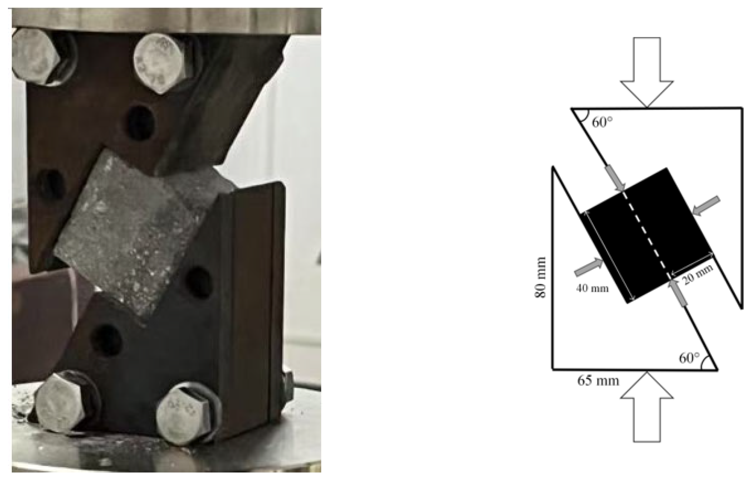
2.5. Interlayer Bond Strength Test

To evaluate interlayer bond strength, cubic specimens of the same size (40 mm × 40 mm × 40 mm) were tested under diagonal compression with a loading rate of 2400 N/s. The experimental procedure strictly adhered to the specifications of GB/T 50081-2019. The experimental setup (Figure 5) mechanically converted the vertical load into a diagonal shearing effect on specimens during downward displacement. The interlayer bond strength was calculated using the following equation:
τ = P sin 60 ° A
where τ is the slant shear strength (MPa), P is the peak shear load (N), and A is the cross-sectional area (mm2).

2.6. Digital Image Correlation (DIC)

To investigate the stress–strain relationship under varying fibre contents, the digital image correlation (DIC in 2D) technique was employed in this study [48]. The DIC system comprised an i-speed 713 ultra-high-speed camera, two 100 W LED illumination sources, and proprietary analysis software. By establishing a correspondence between the reference image and the deformed image using analysis software, 2D-DIC can measure the displacement of deformed objects in a two-dimensional plane and then calculate information such as strain based on the displacement data.
The experiment was applied along the Z direction at a loading rate of 2.4 kN/s, while the camera acquired images at 10 frames per second. The acquisition window encompassed the entire failure process, beginning before specimen deformation and ending after structural collapse. Through computational analysis of the captured image series, comparative analysis of deformation contours and displacement fields enabled a detailed assessment of the stress–strain behaviour.

2.7. X-Ray Powder Diffraction (XRD)

X-ray diffraction (XRD) analysis was conducted to identify crystal structures, lattice parameters, and potential impurity phases. Suitable fragments were extracted from specimens following compressive failure, manually pulverised using an agate mortar, and sieved through a 200-mesh sieve (particle size < 1 mm). The resulting powder was dried in an oven at 85 °C for 6 h and then compacted into pellets for XRD analysis. The measurements were performed over a scanning range of 5–80° at a rate of 2°/min.

2.8. Scanning Electron Microscopy (SEM)

For microstructural observation, intact SFR3DPC specimens and fractured specimens with flat observation surfaces were selected, dried at 85 °C for 6 h, and subsequently mounted onto SEM stubs using conductive adhesive tape. A Hitachi SU8010 scanning electron microscope (Hitachi Ltd., Tokyo, Japan) was used to observe fibre distribution in 3D-printed concrete, with an image resolution of 2560 × 1920 pixels and magnifications ranging from 50× to 2000×.

3. Results and Discussion

3.1. Fresh Properties

The corresponding test results are presented in Figure 6. According to the findings of W. Xu et al., freshly mixed CFREFC is deemed unsuitable for 3D printing when its fluidity falls below 166.72 mm or exceeds 200.93 mm [49]. In this study, the fluidity values ranged between 160 mm and 173 mm, which aligns with the acceptable range reported in their study. The results indicate a reduction in fluidity with fibre incorporation. The highest fluidity was observed in the Mock-0-0-0 group, whereas the BF-0-0-4 group exhibited the lowest. This phenomenon can be attributed to increased cohesion and viscosity resulting from fibre addition, which increases the internal resistance to flow [50,51]. Moreover, a higher fibre content promotes fibre entanglement, further compromising fluidity [52]. Nevertheless, all specimens were successfully fabricated within the experimentally validated fluidity range.

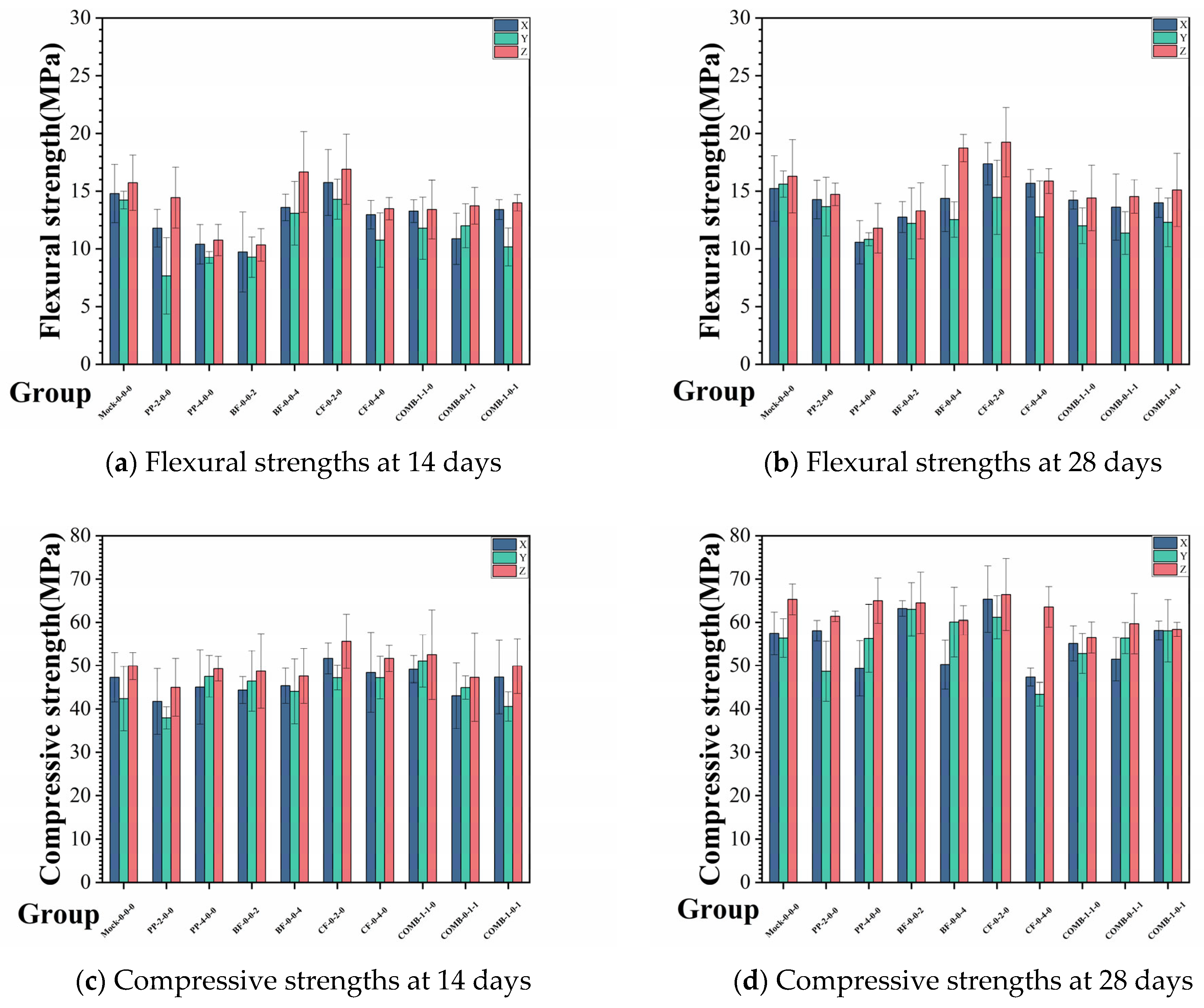
3.2. Mechanical Properties

The development patterns of flexural and compressive strengths under different fibre incorporation conditions are presented in Figure 7. For each variable, three specimens were tested to calculate the average values. In this study, the Mock-0-0-0 group was designated as the control group.
The CF-0-2-0 group exhibited the highest flexural and compressive strengths, reaching 16.9 MPa and 55.6 MPa after 14 days of curing—an increase of 7.4% and 11.4% compared to the control group. After 28 days, the flexural and compressive strengths further increased to 19.2 MPa and 66.4 MPa, representing enhancements of 18.1% and 1.7%. These results indicate that 0.2 wt.% carbon fibre incorporation provides the most substantial improvement in both flexural and compressive properties of SFR3DPC. This is primarily due to the high tensile strength and elastic modulus of carbon fibres, which effectively inhibit crack propagation and enhance material toughness [53]. In contrast, the incorporation of 0.2 wt.% polypropylene (PP) fibres resulted in reductions of 8.2% and 9.8% in flexural and compressive strength, respectively, at 14 days, and 9.6% and 5.9% at 28 days compared to the control group. The BF-0-0-2 group, with 0.2 wt.% basalt fibre, showed even more pronounced reductions in flexural strength—34.3% at 14 days and 18.4% at 28 days—while compressive strength decreased by 2.4% and 1.2%, respectively.
When comparing hybrid fibre systems to single-fibre incorporation, no significant improvement in flexural or compressive performance was observed. For flexural strength, the 14-day results of the hybrid groups were 13.41 MPa, 13.73 MPa, and 13.99 MPa—14.8%, 12.7%, and 11.0% lower than those of the control group, respectively. At 28 days, the values increased slightly to 14.41 MPa, 14.53 MPa, and 15.07 MPa, still 11.5%, 10.7%, and 7.4% lower than those of the control. The compressive strength results for hybrid groups at 14 days were 52.53 MPa, 47.31 MPa, and 49.88 MPa, showing marginal improvements or slight reductions compared to the control (5.2%, 5.2%, and 0.1%, respectively). At 28 days, the compressive strengths were 56.5 MPa, 59.7 MPa, and 58.4 MPa (13.5%, 8.6%, and 10.6% lower than the control group). These findings indicate that the incorporation of hybrid fibres has limitations in terms of improving the mechanical properties. This may be due to the stress concentrations from defects in the damage path.

3.3. Interlayer Bond Strength

The interlayer bond strengths are presented in Figure 8. The COMB-0-1-1 group exhibited the best performance, with strengths of 15.7 MPa at 14 days and 23.4 MPa at 28 days. These values represent increases of 37.8% and 26.7%, respectively, compared to the control group. This result indicates that the hybrid incorporation of basalt and carbon fibres yields the most pronounced enhancement in interlayer bond strength. By comparison, the PP-2-0-0 group achieved improvements of 21.6% at 14 days and 23.7% at 28 days. The CF-0-2-0 group recorded increases of 23.7% and 24.9% at 14 and 28 days, respectively. In contrast, the BF-0-0-2 group, incorporating 0.2 wt.% basalt fibres, showed a reduction in slant shear strength, decreasing by 10.7% at 14 days and 4.3% at 28 days. These findings suggest that while the inclusion of 0.2 wt.% carbon or polypropylene fibres contributes positively to bond performance, the use of basalt fibres at this dosage adversely affects interlayer bonding.
It was found that the enhancement of mechanical properties through fibre blending was generally limited. This may be attributed to the inability of a low overall fibre content to form a dense reinforcement network. The results of the COMB-1-1-0 group were 11.6 MPa at 14 days and 18.9 MPa at 28 days. The COMB-1-0-1 group reached 10.0 MPa at 14 days and 16.1MPa at 28 days. Compared to the control group, there was no significant enhancement or attenuation of the trend. Due to the typically random distribution of fibres in the matrix, the mechanical contributions of hybrid systems may not always be pronounced or consistent [54]. However, the significant improvement in the interlayer bond strength of group COMB-0-1-1 demonstrates a viable option for hybrid fibre groups.
A novel compressive-to-tensile strength ratio metric was introduced to better evaluate the mechanical performance of SFR3DPC [55]. As shown in Figure 9, COMB-0-1-1 demonstrated optimally balanced responses, achieving the lowest C/T ratio values at both 14 and 28 days. This confirms that hybrid fibre systems (e.g., carbon–basalt combinations) contribute substantially to enhancing the toughness of SFR3DPC.

3.4. Anisotropic Behaviour

Figure 10 presents the directional mechanical properties of all specimen groups across three orthogonal axes (X, Y, Z). Comparative analysis reveals consistently higher strength along the Z direction for all SFR3DPC specimens. The representative results from the COMB-0-1-1 group after 28 days of curing exemplify this anisotropic behaviour: the flexural strengths measured 13.6 MPa (X), 11.4 MPa (Y), and 14.5 MPa (Z); the compressive strengths were 51.5 MPa (X), 56.4 MPa (Y), and 59.7 MPa (Z); the slant shear strengths reached 21.1 MPa (X), 22.4 MPa (Y), and 31.2 MPa (Z). This trend of directional dominance was observed across all groups, corroborating the findings of Yang et al. [56]. The superior mechanical performance observed in the Z direction is closely related to the printing method of SFR3DPC. During vertical printing, each layer of concrete is compacted onto the previous one under gravity, resulting in fewer interlayer voids and defects, reduced risk of interlayer separation, and improved overall strength [57].
Based on the mechanical test results for flexural, compressive, and shear properties, which differentiated by fibre type and dosage, it is evident that SFR3DPC exhibits anisotropic behaviour dependent on the loading direction. In this study, the influence of material parameters on the anisotropy of SFR3DPC is quantitatively evaluated using an anisotropy coefficient, calculated as follows [58]:
F ¯ = F x + F y + F z 3
I = F x F ¯ 2 + F y F ¯ 2 + F z F ¯ 2 3
F x , F y , F z represent the strengths measured along the X, Y, and Z directions, respectively. F ¯ is calculated as the average of these three directional strengths. The anisotropy coefficient I is defined as the standard deviation of the directional strengths, where a lower value of I indicates reduced anisotropy, i.e., smaller variation among the three loading directions.
According to Figure 10, the anisotropy coefficients of flexural, compressive, and slant shear strengths for (the control group) cured for 14 days were 0.32, 6.14, and 6.89. For the control group cured for 28 days, the corresponding values were 0.23, 7.81, and 8.85. With fibre incorporation, the anisotropy coefficients for flexural strength exhibited an increasing trend. For compressive strength and slant shear strength, the results of the single-fibre groups generally showed fluctuating behaviour. However, the mixed-fibre groups showed a significant decrease in both areas.
This suggests that fibre incorporation tends to amplify directional variation in flexural strength, whereas its influence on the anisotropy of compressive and slant shear strength is less consistent. The random distribution of fibres may further exacerbate the mechanical performance gap between strong and weak directions in printed specimens, thereby accentuating the anisotropic characteristics of flexural strength in SFR3DPC. However, the anisotropy-reducing effect of hybrid fibre systems sets can be applied to a wider range of engineering applications.

3.5. Effect of Fibre Dosage

Figure 11 presents the 28-day growth rates of mechanical strengths for specimens with different fibre dosages. Overall, flexural strength showed a decreasing trend with increasing fibre content. Compressive strength exhibited relatively small overall fluctuations but more pronounced local variations. In contrast, slant shear strength demonstrated a generally increasing pattern. A detailed comparison revealed that in the PP-4-0-0 group, flexural strength decreased across all three loading directions compared to the PP-2-0-0 group. Specifically, 28-day flexural strengths in the Z direction were 11.79 MPa and 14.72 MPa, in the X direction 10.57 MPa and 14.27 MPa, and in the Y direction 10.82 MPa and 13.66 MPa, respectively. For the basalt fibre groups, compressive strength also decreased with higher dosage. In the BF-0-4-0 group compared to BF-0-2-0, the 28-day compressive strengths in the Z direction were 60.44 MPa and 64.50 MPa; in the Y direction, 60.06 MPa and 63.00 MPa; and in the X direction, 50.25 MPa and 63.19 MPa, respectively. These reductions indicate a negative impact of excessive basalt fibre content on compressive performance. Regarding slant shear strength, the CF-0-4-0 group exhibited a significant reduction compared to the CF-0-2-0 group. The 28-day shear strength in the Z direction decreased from 23.06 MPa to 15.98 MPa.
When the fibre content was increased from 0.2 wt.% to 0.4 wt.%, a decline in mechanical strength was observed. This may be attributed to excessive fibre content leading to agglomeration, which forms stress concentration points and thereby weakens the overall integrity of the SFR3DPC [59]. Furthermore, excessive fibre content can weaken the fibre–matrix interfacial bond, thereby reducing stress transfer efficiency [60]. The 0.2% carbon fibre dosage optimised both workability and fibre dispersion, enabling preferential fibre alignment at interlayer weak zones, thus effectively inhibiting crack propagation [61].
Regarding the costs, carbon fibre demonstrated the highest price at 83.75 CNY/kg, followed by basalt fibre (15.9 CNY/kg), with PP fibre being the most economical at 7.81 CNY/kg. Hybrid fibre implementation achieved notable cost efficiency. This strategy substitutes expensive fibres with lower-priced alternatives, offering concrete guidance for optimising construction budgets.

3.6. Digital Image Correlation Analysis

To investigate the slant shear failure modes of SFR3DPC, the digital image correlation (DIC) technique was employed to analyse stress–strain behaviour and crack propagation patterns. Figure 12 presents the fitted stress–strain curves for each group (the red indicates the fitted curve). It clearly shows that specimens from the CF-0-2-0, PP-2-0-0 and COMB-0-1-1 groups exhibited markedly higher failure stresses compared to the control group (Mock-0-0-0). Additionally, COMB-0-1-1 demonstrated superior ultimate strain performance, in alignment with the results from the interlayer bond strength tests.
High-resolution images and corresponding DIC strain contour maps were captured at stress levels corresponding to 1%, 50%, and 100% of the peak failure stress (Figure 13). The Mock-0-0-0 specimens exhibited typical brittle failure characteristics, with DIC analysis revealing the formation of a single, vertically oriented crack prior to rupture. This crack propagated rapidly and was accompanied by localised stress concentrations, resulting in a limited number of wide cracks. In contrast, the introduction of fibres altered the failure mode toward quasi-brittle behaviour. Polypropylene (PP) fibres improved material ductility, leading to slower and more controlled crack propagation [62]. As shown in Figure 13B, crack propagation no longer follows a vertically penetrating path. This may be attributed to the incorporation of polypropylene fibres that enhance the overall shear strength of the material, increasing the resistance to crack growth and thereby lengthening the crack propagation path. Basalt fibres effectively enhanced crack resistance [63]. DIC images indicated that crack progression was constrained by the presence of fibres, resulting in oblique crack trajectories propagating from the specimen edges toward the centre, likely influenced by internal fibre alignment. Carbon fibres (CFs), characterised by high strength and stiffness, substantially improved material toughness [64]. Fibre bridging prevented penetrating cracks, instead promoting distributed microcracking with narrower crack widths and more complex fracture networks. The hybrid fibre system exhibited a complementary effect during crack propagation [65]. As shown in Figure 13F, carbon fibres, as high-modulus reinforcements, can withstand higher tensile stresses. Basalt fibres, due to their high ductility, can undergo greater deformation and absorb more energy. The complementary action of the two fibres effectively inhibited the formation of penetrating cracks.

3.7. XRD Results

To further investigate the structural changes of SFR3DPC, an X-ray diffraction (XRD) analysis was conducted on specimens cured for 28 days. The results are presented in Figure 14. An analysis of the diffractograms shows that the main diffraction peak corresponds to quartz (SiO2), a primary component derived from silica fume and sand, which appears as a sharp peak near 26°. The presence of SiO2 is also evidenced by additional peaks at 21.7°, 50.9°, 59.7°, and 67.1°. Calcium silicate hydrate (C-S-H) gel, the principal hydration product of cement, has an amorphous structure and typically exhibits broad, diffuse peaks. While distinct diffraction peaks are difficult to identify, a broad hump can be observed in the 29–35° range. An additional crystalline phase, like K(Si3Al) O8(27.6°), was also detected.
Polypropylene fibres, as organic polymers, do not exhibit distinct crystalline peaks and contribute primarily to the broad baseline signal. Basalt fibres, composed predominantly of SiO2 and Al2O3, are chemically stable and do not significantly alter the SFR3DPC’s crystalline structure. Carbon fibres adhere to the cement matrix via physical adsorption without forming chemical bonds. The incorporation of all three fibre types did not cause significant shifts in the peak positions of hydration products such as C-S-H and quartz, although slight variations in peak shapes were observed among groups. This may be attributed to non-uniform fibre dispersion or agglomeration, which affects X-ray penetration depth. Additionally, fibre alignment may influence diffraction intensities from specific crystallographic planes (e.g., those perpendicular to fibre orientation). Certain elements within the fibres may also absorb X-rays, further modifying the detected signal.

3.8. SEM Analysis

Microstructural characterisation of SFR3DPC using scanning electron microscopy (SEM) enables the analysis of internal crack distribution and defect features. As shown in Figure 15a, cementitious materials produce hydration products such as calcium silicate hydrate (C-S-H) gel and calcium hydroxide (CH) crystals during the hydration process, which contribute to the densification of 3D-printed cementitious composites. However, in the absence of fibre reinforcement, the surface exhibits notable particle agglomeration, with large, loosely packed intergranular pores that significantly compromise mechanical strength. This issue is effectively mitigated by fibre incorporation.
Figure 15b–d shows the distribution of polypropylene, basalt, and carbon fibres in SFR3DPC, where their relatively uniform dispersion fills internal voids and reduces defects within the matrix, thereby enhancing structural integrity and mechanical performance. Figure 15e presents the fracture surface of the hybrid fibre group (carbon and basalt fibres), which reveals intertwining and interaction between the two fibre types, contributing to improved composite strength. The fibres remain entangled prior to rupture, and their interaction contributes to the overall mechanical enhancement. Even after rupture, filamentary bridging is observed, further validating the reinforcing interaction between fibres.
During crack propagation, some fibres remain under tensile load within the matrix, while others fracture or are pulled out after exceeding their critical elongation threshold. The fibre fracture morphology and the fibre–matrix bonding state are shown in Figure 16. The images reveal both vertical cleavage and longitudinal tensile failure of the fibres. Stress redistribution occurs within the SFR3DPC matrix, with interconnected fibres acting as stress concentration points. As stress increases, fibres gradually undergo localised necking and partial rupture, yet the remaining segments maintain thread-like continuity and continue to bear tensile loads. During the pull-out process, significant energy is dissipated through frictional resistance and mechanical anchoring at the fibre–matrix interface. Some extracted fibres exhibit torsional deformation and necked fracture surfaces, contributing to a transition from brittle to quasi-brittle failure, consistent with prior observations.
Numerous cement hydration products, including calcium silicate hydrate (C-S-H) gel and calcium hydroxide (CH) crystals, are visibly adhered to the fibre surfaces. This enhances interfacial bonding and matrix densification. Even under failure conditions, small crystalline particles continue to maintain fibre adhesion to the matrix surface, thereby reducing interfacial voids. The combined embedding and bridging effects of the fibres significantly increase the specimen’s ultimate load-bearing capacity, as reflected in improvements in mechanical strengths.

4. Conclusions

In this study, the effects of dosages (0.2 wt.% and 0.4 wt.% for single incorporation, and 0.1 wt.% + 0.1 wt.% for hybrid incorporation) with three fibre types (polypropylene, basalt and carbon fibre) were systematically investigated. The evaluation included flowability, mechanical performance under different loading directions, interlayer bond strength, and microstructural characteristics of short-fibre-reinforced 3D-printed cementitious composites (SFR3DPC). The feasibility and effectiveness of single and hybrid fibre incorporation strategies were comprehensively assessed. The following conclusions were drawn based on the experimental results:
  • Fibre addition increased the cohesion and viscosity of the concrete, resulting in reduced flowability. Nevertheless, all mixtures exhibited flowability in the range of 160–173 mm, which were suitable for 3D printing. Adequate fluidity ensured that all specimens could be successfully printed and reliably evaluated for mechanical and microstructural properties.
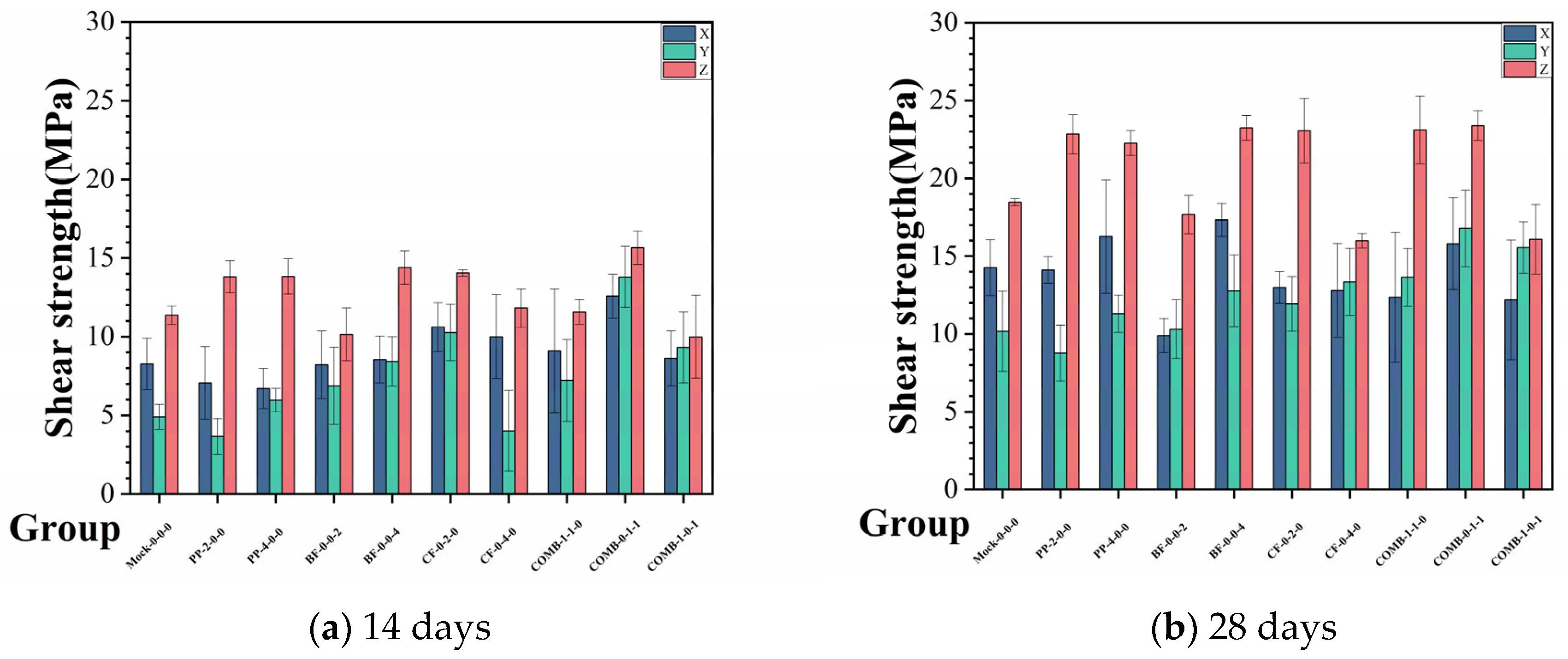
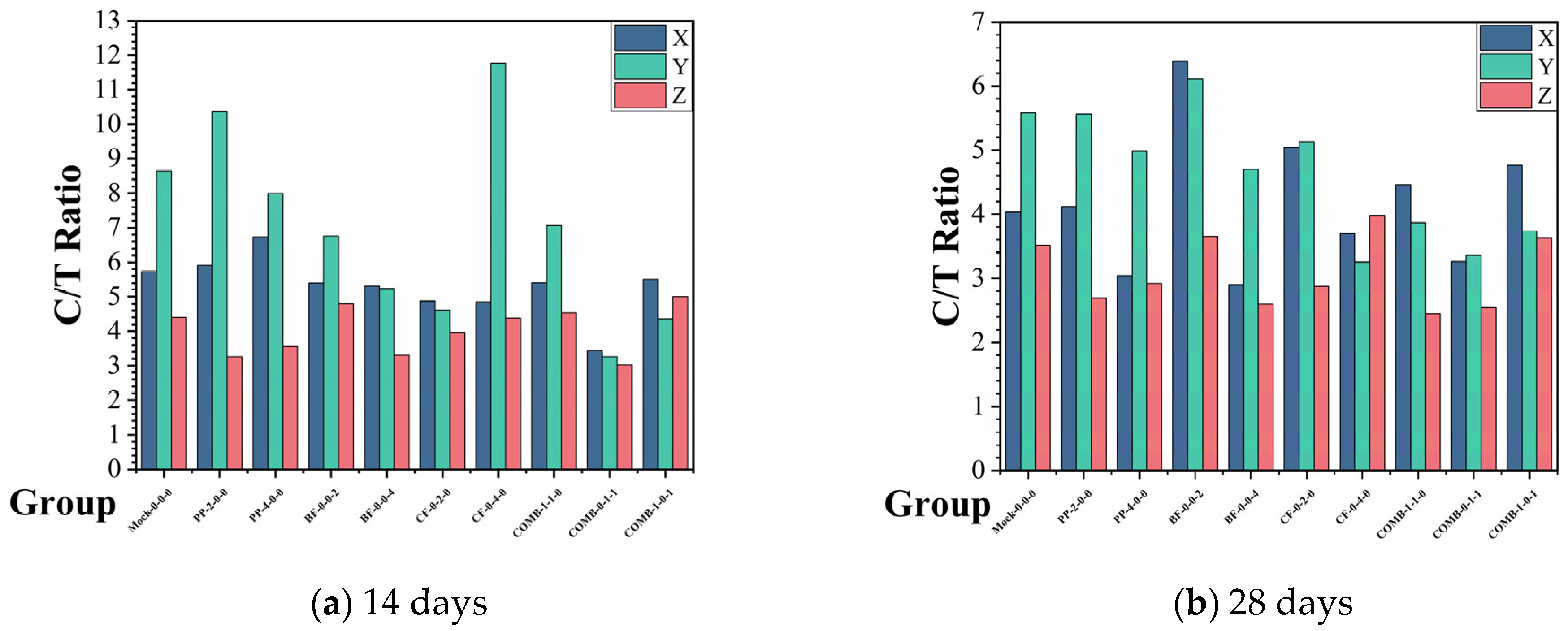
  • SFR3DPC exhibited mechanical anisotropy across different loading directions. The highest strength was consistently observed in the Z direction. Fibre incorporation further intensified the anisotropy in flexural strengths. However, the hybrid fibre systems also perform well in reducing the anisotropy of SFR3DPC, making up for the shortcomings in different directions. This provides guidance for the stress surface and failure surface of engineering construction, thereby improving engineering safety.
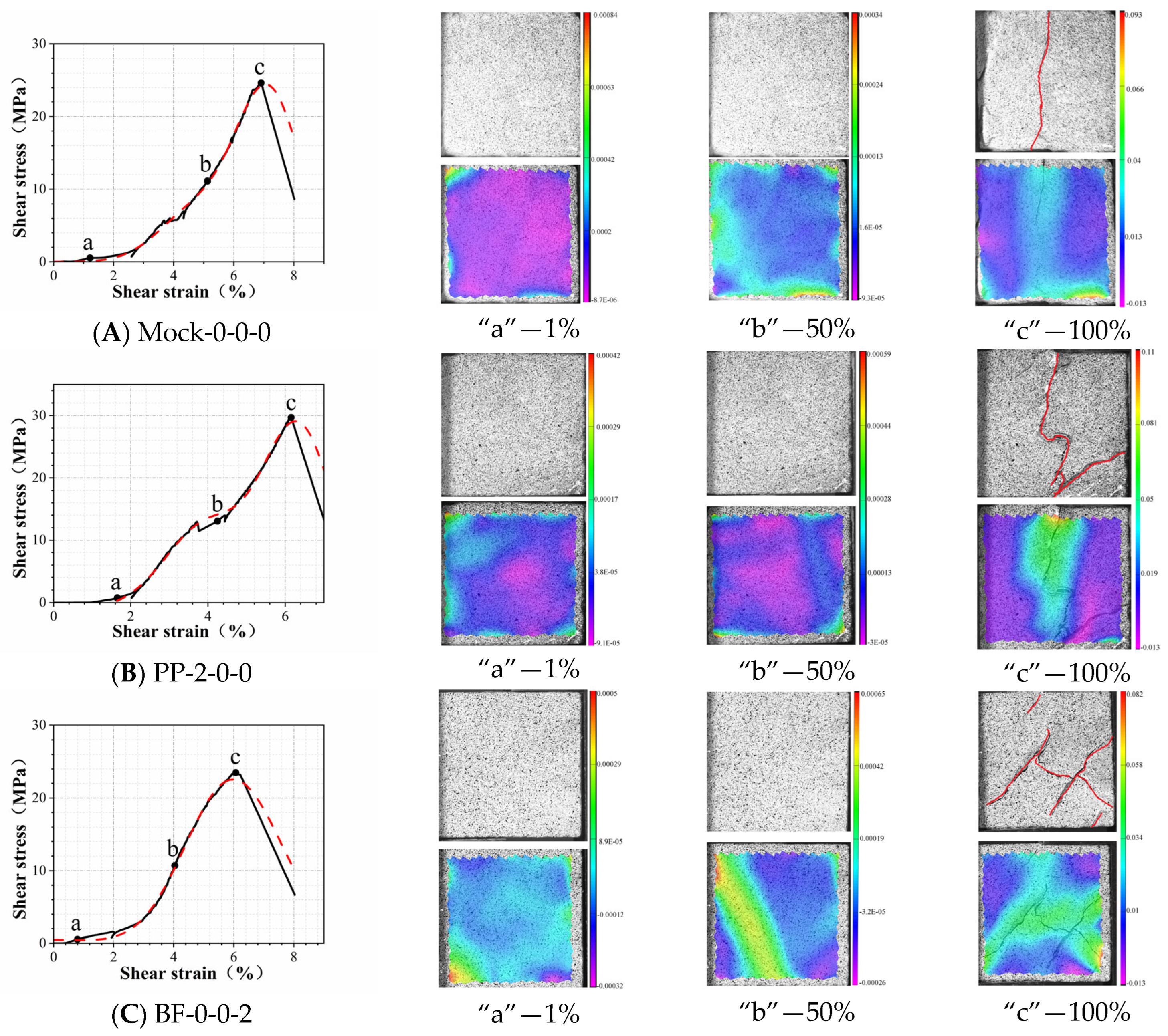
  • Among all the groups, the hybrid incorporation of 0.1 wt.% carbon fibre and 0.1 wt.% basalt fibre resulted in the greatest improvement in interlayer bond strength, reaching 23.38 MPa at 28 days, a 26.7% increase compared to the control group. This shows the advantages of hybrid fibre systems. Combined with the DIC images, it can be observed that the improvement in the interlayer bond strength of the hybrid fibre systems is also reflected in crack refinement. The fact that cracks are less likely to penetrate the structure is also instructive in terms of safety in engineering applications.
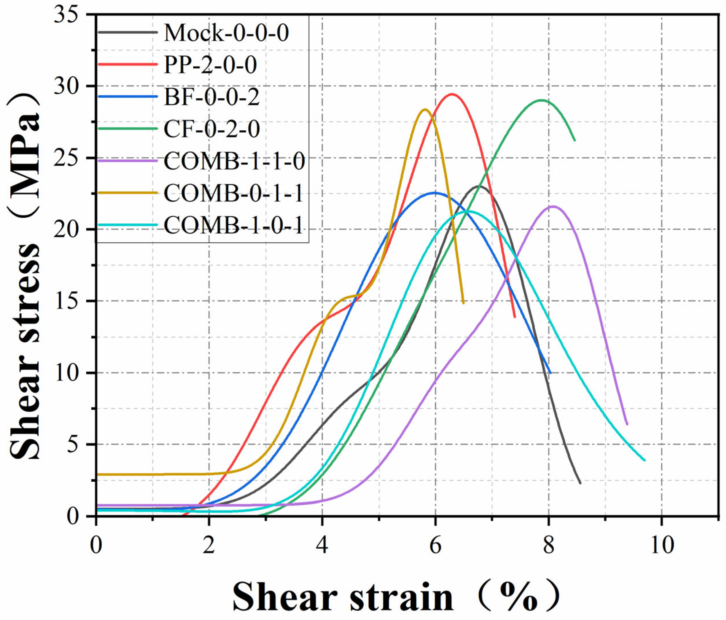
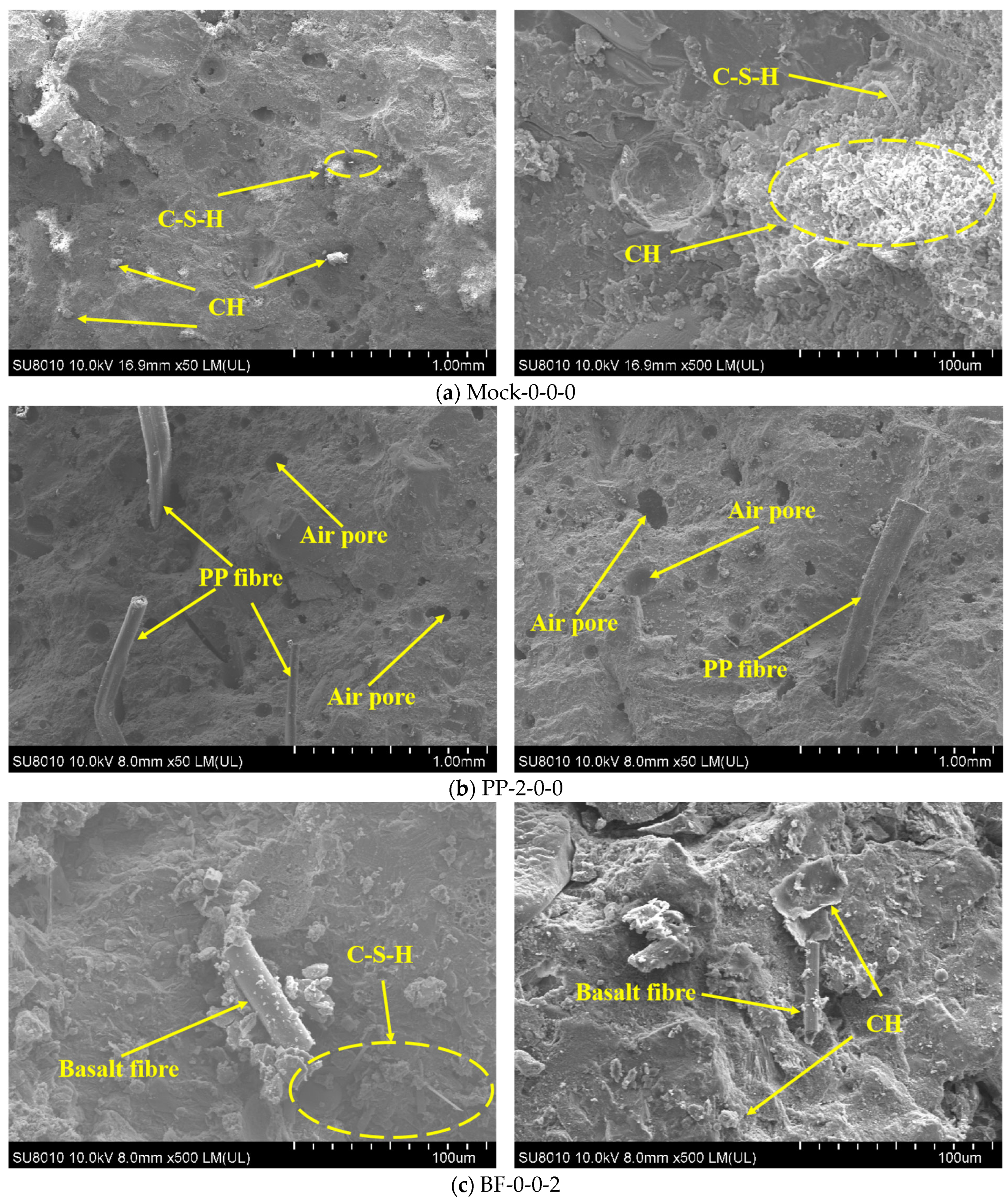
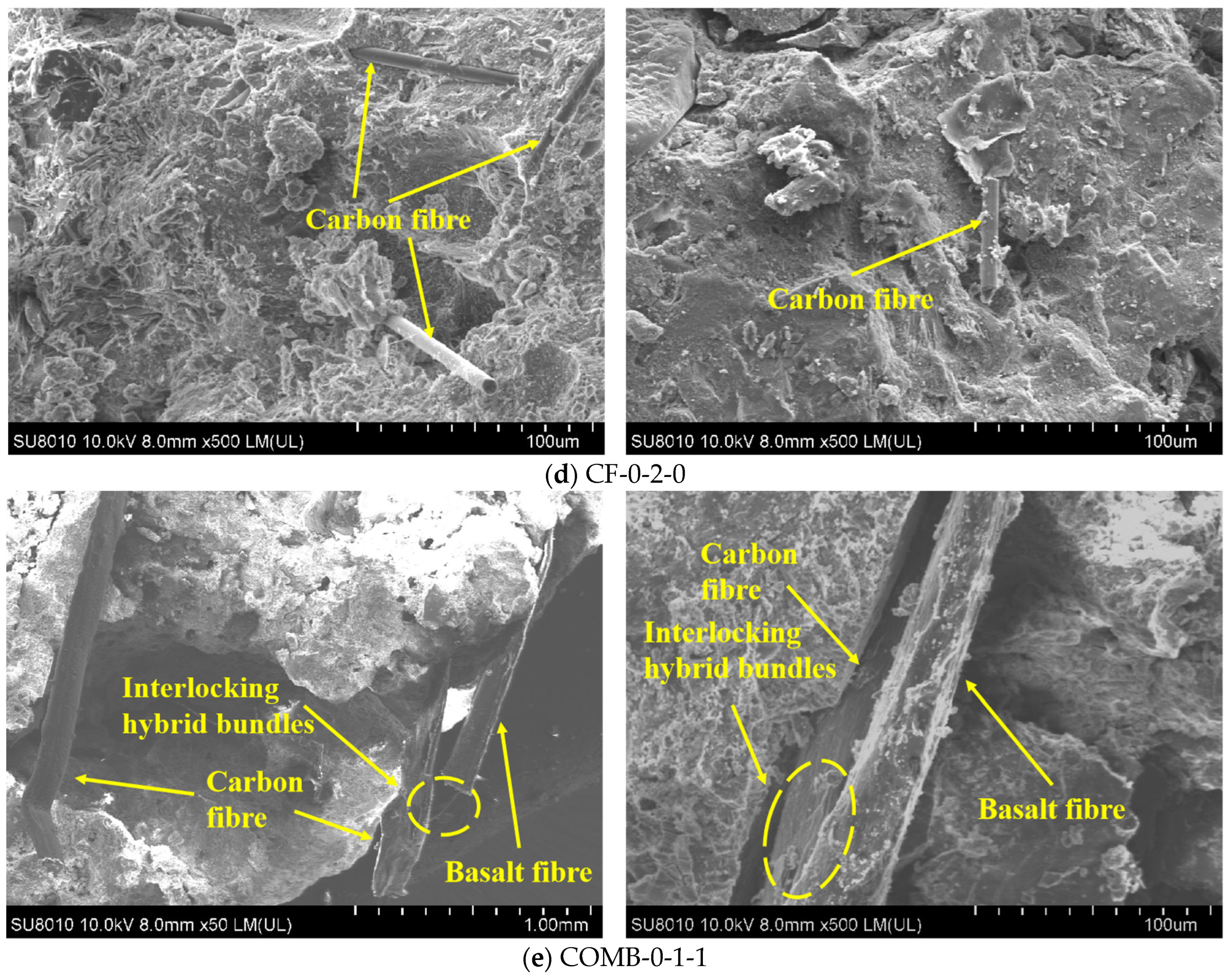
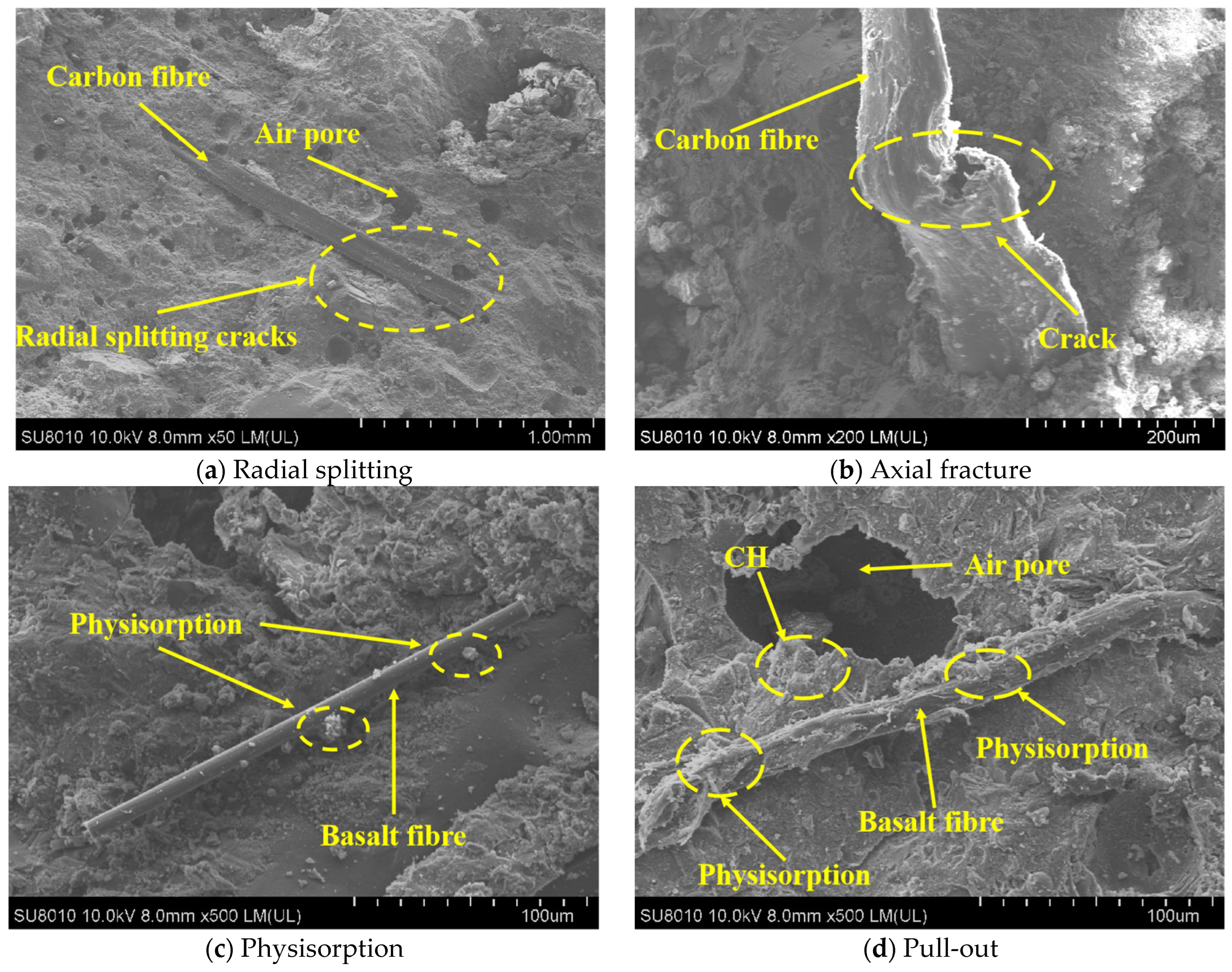
  • The addition of fibres transformed the failure mode from typical brittle fracture to quasi-brittle behaviour. XRD and SEM analyses revealed that fibre reinforcement occurred primarily through physical adhesion rather than chemical bonding. The incorporation of fibres will not affect the hydration process of SFR3DPC and maintain the internal stability of the composite. While the mechanical enhancement of hybrid fibre systems was not always superior, the synergistic interaction among different fibre types facilitated crack deflection and bridging, contributing to a more desirable fracture pattern.
  • Higher fibre dosages tended to cause fibre agglomeration and uneven dispersion, increasing internal porosity and reducing reinforcement efficiency. In contrast, the 0.2 wt.% dosage provided an optimal balance between dispersion and performance enhancement. Also, due to the high cost of carbon fibres, the hybrid fibre systems (COMB-0-1-1) are also advantageous in terms of cost effectiveness. This study also has profound implications in material savings and cost savings.
Future studies should focus on optimising both fibre dosage and hybridisation strategies to mitigate issues such as fibre agglomeration and increased porosity at higher contents. Addressing the directional anisotropy exacerbated by random fibre alignment remains critical for performance consistency. Furthermore, integrating advanced sensing technologies to investigate fibre–matrix interfacial mechanisms at the microscale may provide deeper theoretical insights and practical guidance for the engineering application of high-performance 3D-printed cementitious composites.

Author Contributions

H.Y.: conceptualisation, methodology, investigation and original draft. Y.C.: writing and formal analysis. Z.X.: methodology and formal analysis. Y.M.: reviewing and editing, funding acquisition. All authors have read and agreed to the published version of the manuscript.

Funding

This research received no external funding.

Data Availability Statement

Data are contained within the article.

Conflicts of Interest

The authors declare no conflicts of interest.

References

  1. Liu, D.; Zhang, Z.; Zhang, X.; Chen, Z. 3D printing concrete structures: State of the art, challenges, and opportunities. Constr. Build. Mater. 2023, 405, 133364. [Google Scholar] [CrossRef]
  2. Şahin, H.G.; Mardani-Aghabaglou, A. Assessment of materials, design parameters and some properties of 3D printing concrete mixtures; a state-of-the-art review. Constr. Build. Mater. 2022, 316, 125865. [Google Scholar] [CrossRef]
  3. Huang, X.; Yang, W.; Song, F.; Zou, J. Study on the mechanical properties of 3D printing concrete layers and the mechanism of influence of printing parameters. Constr. Build. Mater. 2022, 335, 127496. [Google Scholar] [CrossRef]
  4. Schuldt, S.J.; Jagoda, J.A.; Hoisington, A.J.; Delorit, J.D. A systematic review and analysis of the viability of 3D-printed construction in remote environments. Autom. Constr. 2021, 125, 103642. [Google Scholar] [CrossRef]
  5. Dey, D.; Srinivas, D.; Panda, B.; Suraneni, P.; Sitharam, T.G. Use of industrial waste materials for 3D printing of sustainable concrete: A review. J. Clean. Prod. 2022, 340, 130749. [Google Scholar] [CrossRef]
  6. Khan, M.; Mcnally, C. Recent developments on low carbon 3D printing concrete: Revolutionizing construction through innovative technology. Clean. Mater. 2024, 12, 100251. [Google Scholar] [CrossRef]
  7. Yang, Y.; Wu, C.; Liu, Z.; Wang, H.; Ren, Q. Mechanical anisotropy of ultra-high performance fibre-reinforced concrete for 3D printing. Cem. Concr. Compos. 2022, 125, 104310. [Google Scholar] [CrossRef]
  8. Robayo-Salazar, R.; Mejía De Gutiérrez, R.; Villaquirán-Caicedo, M.A.; Delvasto Arjona, S. 3D printing with cementitious materials: Challenges and opportunities for the construction sector. Autom. Constr. 2023, 146, 104693. [Google Scholar] [CrossRef]
  9. Yan, K.; Li, L.; Ye, J.; Bazarov, D.; Deng, B.; Yu, K. Anisotropic size effect of 3D printed LC3-based engineered cementitious composites (LC3-ECC). J. Build. Eng. 2024, 92, 109668. [Google Scholar] [CrossRef]
  10. Shen, D.; Liu, X.; Zeng, X.; Zhao, X.; Jiang, G. Effect of polypropylene plastic fibers length on cracking resistance of high performance concrete at early age. Constr. Build. Mater. 2020, 244, 117874. [Google Scholar] [CrossRef]
  11. Cao, J.; Shengzhao, E.; Yang, Y.; Shi, Y.; Chai, J.; Xu, Z. A strategy for the improvement of the bonding performance of 3D-printed concrete interlayer interfaces. J. Build. Eng. 2024, 97, 110675. [Google Scholar] [CrossRef]
  12. Liu, F.; Fan, C.; Wang, B.; Zhou, C.; Chen, Z. Comparative study of interfacial debonding mechanism of fiber pull-out in magnesium phosphate cementitious composites. J. Build. Eng. 2025, 102, 111901. [Google Scholar] [CrossRef]
  13. Ahmad, J.; Zhou, Z. Mechanical Properties of Natural as well as Synthetic Fiber Reinforced Concrete: A Review. Constr. Build. Mater. 2022, 333, 127353. [Google Scholar] [CrossRef]
  14. Kazemi, F.; Shafighfard, T.; Yoo, D. Data-Driven Modeling of Mechanical Properties of Fiber-Reinforced Concrete: A Critical Review. Arch. Comput. Methods Eng. 2024, 31, 2049–2078. [Google Scholar] [CrossRef]
  15. Zheng, Y.; Lv, X.; Hu, S.; Zhuo, J.; Wan, C.; Liu, J. Mechanical properties and durability of steel fiber reinforced concrete: A review. J. Build. Eng. 2024, 82, 108025. [Google Scholar] [CrossRef]
  16. Peng, S.; Wu, B.; Du, X.; Zhao, Y.; Yu, Z. Study on dynamic splitting tensile mechanical properties and microscopic mechanism analysis of steel fiber reinforced concrete. Structures 2023, 58, 105502. [Google Scholar] [CrossRef]
  17. Liew, K.M.; Akbar, A. The recent progress of recycled steel fiber reinforced concrete. Constr. Build. Mater. 2020, 232, 117232. [Google Scholar] [CrossRef]
  18. Zhang, P.; Wang, C.; Gao, Z.; Wang, F. A review on fracture properties of steel fiber reinforced concrete. J. Build. Eng. 2023, 67, 105975. [Google Scholar] [CrossRef]
  19. Ribeiro, R.P.; Jaramillo Nieves, L.J.; Bernardin, A.M. Effect of fiberglass waste and fly ash addition on the mechanical performance of Portland cement paste. Clean. Mater. 2023, 7, 100176. [Google Scholar] [CrossRef]
  20. Al-Kharabsheh, B.N.; Arbili, M.M.; Majdi, A.; Alogla, S.M.; Hakamy, A.; Ahmad, J.; Deifalla, A.F. Basalt Fiber Reinforced Concrete: A Compressive Review on Durability Aspects. Materials 2023, 16, 429. [Google Scholar] [CrossRef] [PubMed]
  21. Gong, L.; Yu, X.; Liang, Y.; Gong, X.; Du, Q. Multi-scale deterioration and microstructure of polypropylene fiber concrete by salt freezing. Case Stud. Constr. Mater. 2023, 18, e1762. [Google Scholar] [CrossRef]
  22. Soni, A.; Kumar, S.; Majumder, B.; Dam, H.; Dutta, V.; Das, P.K. Synergy of waste plastics and natural fibers as sustainable composites for structural applications concerning circular economy. Environ. Sci. Pollut. Res. Int. 2024, 31, 38846–38865. [Google Scholar] [CrossRef] [PubMed]
  23. Solahuddin, B.A.; Yahaya, F.M. A narrative review on strengthening of reinforced concrete beams using carbon fibre reinforced polymer composite material through experimental investigation and numerical modelling. Structures 2023, 52, 666–710. [Google Scholar] [CrossRef]
  24. Muthukumarana, T.V.; Arachchi, M.A.V.H.; Somarathna, H.M.C.C.; Raman, S.N. A review on the variation of mechanical properties of carbon fibre-reinforced concrete. Constr. Build. Mater. 2023, 366, 130173. [Google Scholar] [CrossRef]
  25. Bakhshi, A.; Zafar, M.S.; Hojati, M. A study on achieving high tensile ductility in 3D-Printable engineered cementitious composites reinforced with 8 mm fibers. J. Build. Eng. 2025, 103, 112196. [Google Scholar] [CrossRef]
  26. Wang, S.; Yang, R.; Li, Y.; Yue, Z. Effects of cement content, polypropylene fiber length and dosage on fluidity and mechanical properties of fiber-toughened cemented aeolian sand backfill. Int. J. Miner. Metall. Mater. 2024, 31, 2404–2416. [Google Scholar] [CrossRef]
  27. Liu, Z.; Wang, Y.; Meng, Y.; Han, Z.; Jin, T. Comprehensive performance evaluation of steel fiber-reinforced asphalt mixture for induction heating. Int. J. Pavement. Eng. 2022, 23, 3838–3849. [Google Scholar] [CrossRef]
  28. Vairagade, V.S.; Dhale, S.A. Hybrid fibre reinforced concrete—A state of the art review. Hybrid Adv. 2023, 3, 100035. [Google Scholar] [CrossRef]
  29. Yousefi, M.; Khandestani, R.; Gharaei-Moghaddam, N. Flexural behavior of reinforced concrete beams made of normal and polypropylene fiber-reinforced concrete containing date palm leaf ash. Structures 2022, 37, 1053–1068. [Google Scholar] [CrossRef]
  30. Chen, X.; Ai, Y.; Wu, Q.; Cheng, S.; Wei, Y.; Xu, X.; Fan, T. Potential use of nano calcium carbonate in polypropylene fiber reinforced recycled aggregate concrete: Microstructures and properties evaluation. Constr. Build. Mater. 2023, 400, 132871. [Google Scholar] [CrossRef]
  31. Xie, H.; Yang, L.; Zhang, Q.; Huang, C.; Chen, M.; Zhao, K. Research on energy dissipation and damage evolution of dynamic splitting failure of basalt fiber reinforced concrete. Constr. Build. Mater. 2022, 330, 127292. [Google Scholar] [CrossRef]
  32. Zhang, X.; Lou, C.; Lyu, X. Experimental study on direct tensile fatigue performance of basalt fiber reinforced concrete. Sci. Rep. 2024, 14, 765. [Google Scholar] [CrossRef] [PubMed]
  33. Liu, X.; Wang, S.; Han, F.; Qin, J.; Lu, L.; Xue, Q.; Ji, Y. Mechanical relationship between compressive strength and sulfate erosion depth of basalt fiber reinforced concrete. Constr. Build. Mater. 2024, 411, 134412. [Google Scholar] [CrossRef]
  34. Fu, Q.; Zhou, Z.; Wang, Z.; Huang, J.; Niu, D. Insight into dynamic compressive response of carbon nanotube/carbon fiber-reinforced concrete. Cem. Concr. Compos. 2022, 129, 104471. [Google Scholar] [CrossRef]
  35. Wang, H.; He, X.; Zhou, M.; Wei, B.; Wu, W.; Zhou, G.; He, J. A study on the tensile fracture behavior of polypropylene fiber reinforced concrete based on a microscale model. Constr. Build. Mater. 2024, 417, 135291. [Google Scholar] [CrossRef]
  36. Wu, H.; Qin, X.; Huang, X.; Kaewunruen, S. Engineering, Mechanical and Dynamic Properties of Basalt Fiber Reinforced Concrete. Materials 2023, 16, 623. [Google Scholar] [CrossRef] [PubMed]
  37. Chen, Z.; Yang, J. Experimental Study on Dynamic Splitting Characteristics of Carbon Fiber Reinforced Concrete. Materials 2021, 14, 94. [Google Scholar] [CrossRef] [PubMed]
  38. Ma, J.; Yuan, H.; Zhang, J.; Zhang, P. Enhancing concrete performance: A comprehensive review of hybrid fiber reinforced concrete. Structures 2024, 64, 106560. [Google Scholar] [CrossRef]
  39. Hosseinzadeh, H.; Masoud Salehi, A.; Mehraein, M.; Asadollahfardi, G. The effects of steel, polypropylene, and high-performance macro polypropylene fibers on mechanical properties and durability of high-strength concrete. Constr. Build. Mater. 2023, 386, 131589. [Google Scholar] [CrossRef]
  40. Liu, M.; Guo, Z.; Qian, Y.; Chen, L.; Mao, X.; Zhao, J.; Yang, D. Investigation into the long-term alkali resistance of basalt fibers. J. Build. Eng. 2024, 98, 111105. [Google Scholar] [CrossRef]
  41. He, S.; He, J.; Guo, X.; Ueda, T.; Wang, Y. Detection of CFRP-concrete interfacial defects by using electrical measurement. Compos. Struct. 2022, 295, 115843. [Google Scholar] [CrossRef]
  42. Song, F.; Chen, Q.; Zheng, Q. Multifunctional ultra-high performance fibre-reinforced concrete with integrated self-sensing and repair capabilities towards in-situ structure monitoring. Compos. Struct. 2023, 321, 117240. [Google Scholar] [CrossRef]
  43. Piao, R.; Woo, S.Y.; Lee, D.; Jeong, C.K.; Banthia, N.; Yoo, D. Investigating the effect of carbon fiber dosage on the mechanical and thermoelectric properties of ultra-high-performance fiber-reinforced concrete. J. Sustain. Cem. Based Mater. 2025, 1–15. [Google Scholar] [CrossRef]
  44. Yang, Y.; Tan, Y.; Li, Z.; Zhou, G.; Yu, X.; Xu, D.; Yong, Q.; Zhao, H.; Xie, Z. Interaction mechanisms between polycarboxylate superplasticizers and cement, and the influence of functional groups on superplasticizer performance: A review. Polym. Bull. 2024, 81, 10415–10438. [Google Scholar] [CrossRef]
  45. Gu, X.; Wang, S.; Liu, J.; Wang, H.; Xu, X.; Wang, Q.; Zhu, Z. Effect of hydroxypropyl methyl cellulose (HPMC) as foam stabilizer on the workability and pore structure of iron tailings sand autoclaved aerated concrete. Constr. Build. Mater. 2023, 376, 130979. [Google Scholar] [CrossRef]
  46. Xu, Z.; Zhang, D.; Li, H.; Sun, X.; Zhao, K.; Wang, Y. Effect of FA and GGBFS on compressive strength, rheology, and printing properties of cement-based 3D printing material. Constr. Build. Mater. 2022, 339, 127685. [Google Scholar] [CrossRef]
  47. GB/T 50081-2019; Standard Test Methods for Physical and Mechanical Properties of Concrete. Standardization Administration of China: Beijing, China, 2019.
  48. Golewski, G.L. Comparative measurements of fracture toughgness combined with visual analysis of cracks propagation using the DIC technique of concretes based on cement matrix with a highly diversified composition. Theor. Appl. Fract. Mech. 2022, 121, 103553. [Google Scholar] [CrossRef]
  49. Xu, W.; Jiang, D.; Zhao, Q.; Wang, L. Study on printability of 3D printing carbon fiber reinforced eco-friendly concrete: Characterized by fluidity and consistency. Case Stud. Constr. Mater. 2024, 21, e3589. [Google Scholar] [CrossRef]
  50. Rahman, M.; Rawat, S.; Yang, R.C.; Mahil, A.; Zhang, Y.X. A comprehensive review on fresh and rheological properties of 3D printable cementitious composites. J. Build. Eng. 2024, 91, 109719. [Google Scholar] [CrossRef]
  51. Sun, X.; Zhou, J.; Wang, Q.; Shi, J.; Wang, H. PVA fibre reinforced high-strength cementitious composite for 3D printing: Mechanical properties and durability. Addit. Manuf. 2022, 49, 102500. [Google Scholar] [CrossRef]
  52. Saberian, M.; Tajaddini, A.; Li, J.; Zhang, G.; Wang, L.; Sun, D.; Maqsood, T.; Roychand, R. Mechanical properties of polypropylene fibre reinforced recycled concrete aggregate for sustainable road base and subbase applications. Constr. Build. Mater. 2023, 405, 133352. [Google Scholar] [CrossRef]
  53. Du, Y.; Lu, S.; Xu, J.; Xia, W.; Wang, T.; Wang, Z. Experimental study of impact mechanical and microstructural properties of modified carbon fiber reinforced concrete. Sci. Rep. 2022, 12, 12928. [Google Scholar] [CrossRef] [PubMed]
  54. Bai, W.; Li, Y.; Gong, Z.; And Liu, J. A new method for generating the random fiber arrangement of representative volume element for unidirectional fiber reinforced composites. Mech. Adv. Mater. Struct. 2024, 31, 6035–6043. [Google Scholar] [CrossRef]
  55. Sadat, H.A.; Sadeghian, P. Assessing Compressive Properties of GFRP Bars: Novel Test Fixture and Statistical Analysis. J. Compos. Constr. 2025, 29, 4025011. [Google Scholar] [CrossRef]
  56. Yang, C.; Xu, X.; Lei, Z.; Sun, J.; Wang, Y.; Luo, G.; Yao, H.; Mei, Y. Enhancing mechanical properties of three-dimensional concrete at elevated temperatures through recycled ceramic powder treatment methods. J. Mater. Res. Technol. 2024, 31, 434–446. [Google Scholar] [CrossRef]
  57. Lei, C.; Xie, Z.; Wu, K.; Fu, Q. Controlled Vertically Aligned Structures in Polymer Composites: Natural Inspiration, Structural Processing, and Functional Application. Adv. Mater. 2021, 33, 2103495. [Google Scholar] [CrossRef] [PubMed]
  58. Surehali, S.; Tripathi, A.; Neithalath, N. Anisotropy in Additively Manufactured Concrete Specimens under Compressive Loading—Quantification of the Effects of Layer Height and Fiber Reinforcement. Materials 2023, 16, 5488. [Google Scholar] [CrossRef] [PubMed]
  59. Burbano-Garcia, C.; Araya-Letelier, G.; Astroza, R.; Silva, Y.F. Adobe mixtures reinforced with fibrillated polypropylene fibers: Physical/mechanical/fracture/durability performance and its limits due to fiber clustering. Constr. Build. Mater. 2022, 343, 128102. [Google Scholar] [CrossRef]
  60. Zhang, N.; Yan, C.; Li, L.; Khan, M. Assessment of fiber factor for the fracture toughness of polyethylene fiber reinforced geopolymer. Constr. Build. Mater. 2022, 319, 126130. [Google Scholar] [CrossRef]
  61. Zaid, O.; El Ouni, M.H. Advancements in 3D printing of cementitious materials: A review of mineral additives, properties, and systematic developments. Constr. Build. Mater. 2024, 427, 136254. [Google Scholar] [CrossRef]
  62. Zhang, X.; Yin, R.; Chen, Y.; Lou, C. Experimental study on the axial tensile properties of polypropylene fiber reinforced concrete. Sci. Rep. 2023, 13, 16383. [Google Scholar] [CrossRef] [PubMed]
  63. He, J.; Lei, D.; She, Z.; Xi, B. Flexural performance and damage evaluation on basalt fiber reinforced polymer (BFRP) sheet reinforced concrete. Constr. Build. Mater. 2023, 395, 132321. [Google Scholar] [CrossRef]
  64. Liu, B.; Ye, J.; Liu, X.; Lin, W.; Deng, Z.; Liu, Q. Shear strength and failure criterion of carbon fiber reinforced coral concrete under combined compression-shear stresses. Constr. Build. Mater. 2022, 325, 126728. [Google Scholar] [CrossRef]
  65. Li, K.; Yang, C.; Huang, W.; Zhao, Y.; Wang, Y.; Pan, Y.; Xu, F. Effects of hybrid fibers on workability, mechanical, and time-dependent properties of high strength fiber-reinforced self-consolidating concrete. Constr. Build. Mater. 2021, 277, 122325. [Google Scholar] [CrossRef]
Figure 1. Granulometry of the fine and coarse sand.
Buildings 15 02519 g001
Figure 2. Surface texture of three fibres: (a) PP fibre, (b) basalt fibre and (c) carbon fibre.
Buildings 15 02519 g002
Figure 3. Preparation procedure of test specimens.
Buildings 15 02519 g003
Figure 4. Print direction.
Buildings 15 02519 g004
Figure 5. Schematics of the specimens used in the slant shear studies.
Buildings 15 02519 g005
Figure 6. Fluidity of the fresh mixtures.
Buildings 15 02519 g006
Figure 7. Mechanical properties of (a) flexural strengths at 14 days, (b) flexural strengths at 28 days, (c) compressive strengths at 14 days, (d) compressive strengths at 28 days.
Buildings 15 02519 g007
Figure 8. Interlayer bond strength of (a) 14 days and (b) 28 days.
Buildings 15 02519 g008
Figure 9. Compressive-to-tensile strength ratio of (a) 14 days and (b) 28 days.
Buildings 15 02519 g009
Figure 10. Standard deviation in three directions of (a) 14 days and (b) 28 days.
Buildings 15 02519 g010
Figure 11. Growth rate of mechanical strengths at 28 days in three loading directions: (a) flexural strengths, (b) compressive strengths, (c) slant shear strengths.
Buildings 15 02519 g011
Figure 12. Stress–strain fitted curves.
Buildings 15 02519 g012
Figure 13. Original DIC fracture images and strain fields of (A) Mock-0-0-0, (B) PP-2-0-0, (C) BF-0-0-2, (D) CF-0-2-0, (E) COMB-1-1-0, (F) COMB-0-1-1, (G) COMB-1-0-1.
Buildings 15 02519 g013aBuildings 15 02519 g013b
Figure 14. XRD spectra of seven materials with varying mixing ratios.
Buildings 15 02519 g014
Figure 15. SEM images of (a) Mock-0-0-0, (b) PP-2-0-0, (c) BF-0-0-2, (d) CF-0-2-0, (e) COMB-0-1-1.
Buildings 15 02519 g015aBuildings 15 02519 g015b
Figure 16. SEM images of (a) radial splitting, (b) axial fracture, (c) physisorption, (d) pull-out.
Buildings 15 02519 g016
Table 1. Elemental compositions of the OPC and SF.
MaterialsCaOSiO2Fe2O3Al2O3MgOSO3K2ONa2O
OPC64.1220.732.754.141.252.710.890.44
SF0.1198.120.090.410.050.470.06\
Table 2. Quantitative characterisation of three fibres.
MaterialsLength (mm)Diameter (μm)Tensile Strength (MPa)Density (g/cm3)Fracture Elongation (%)Elasticity Modulus (GPa)
PP3.0 ± 0.057.0\0.91273–4
BF30002.64\91–110
CF41201.761.82230–300
Table 3. Mix design proportions (kg/m3).
GroupCementSFFine SandCoarse SandPPCFBFHPMCPCEWater
Mock-0-0-010001006903000001.282352
PP-2-0-010001006903002001.282352
PP-4-0-010001006903004001.282352
BF-0-0-210001006903000021.282352
BF-0-0-410001006903000041.282352
CF-0-2-010001006903000201.282352
CF-0-4-010001006903000401.282352
COMB-1-1-010001006903001101.282352
COMB-0-1-110001006903000111.282352
COMB-1-0-110001006903001011.282352
Disclaimer/Publisher’s Note: The statements, opinions and data contained in all publications are solely those of the individual author(s) and contributor(s) and not of MDPI and/or the editor(s). MDPI and/or the editor(s) disclaim responsibility for any injury to people or property resulting from any ideas, methods, instructions or products referred to in the content.

