Article

The Influence of Boundary Conditions on the Seismic Resistance of Retrofitted Ancient Masonry Towers

Faculty of Civil Engineering, Architecture and Geodesy, University of Split, Matice Hrvatske 15, 21000 Split, Croatia
*
Author to whom correspondence should be addressed.
Buildings 2025, 15(14), 2495; https://doi.org/10.3390/buildings15142495
Submission received: 12 June 2025 / Revised: 9 July 2025 / Accepted: 14 July 2025 / Published: 16 July 2025
(This article belongs to the Special Issue Challenges in Structural Repairs and Renovations)

Abstract

Historic masonry towers represent a significant part of the cultural heritage, which is often subject to retrofitting for preservation purposes. Due to the poor quality of the mortar, if present at all, the connection of existing towers to the foundation is generally such that it cannot ensure their monolithic behaviour under seismic action. When choosing a retrofitting technique, engineers often find themselves in a dilemma, whether to strengthen the connection between the tower and the foundation in order to enable the transfer of bending moments from the tower to the foundation due to seismic action, or to leave the towers freely rested on the foundation in order to enable the rocking motion mechanism. The aim of this paper was to investigate how the connection between the tower and the foundation affects the seismic resistance of masonry towers. For this purpose, a series of numerical analyses were performed on 2D numerical models that were created based on the geometry of five towers from the Italian region. In these numerical analyses, each of the towers is subjected to an incremental dynamic analysis in time for the case that it is freely supported on the base and for the case that it is freely rested base. The numerical analyses showed that: (i) unretrofitted towers have relatively low seismic resistance and rocking mechanisms cannot be realised to a significant extent; (ii) retrofitted masonry towers resting freely on the base have a significantly higher seismic resistance compared to the same towers connected to the base due to the rocking motion mechanism. The conclusions drawn on the basis of the conducted studies can serve engineers when choosing a technique for strengthening masonry towers.

1. Introduction

Masonry towers are a very old type of structures that have been built for various purposes since prehistoric times. There are, among others, defence towers, bell towers, minarets, and signal towers. Today, these structures form a significant part of cultural heritage. In order to preserve them for future generations and make the right decisions regarding their potential retrofitting, it is necessary to understand their structural behaviour under different types of stress to which they are subjected, with earthquake being the most destructive. For example, many structures of this type were damaged by the earthquakes on 6 February 2023 in the Turkish province of Adıyaman [1]. The earthquakes in Puebla and Morelos, Mexico, in September 2017 [2], the recent earthquakes in Italy [3,4] and the earthquake in Zagreb (Croatia) on 22 March 2020 [5] also damaged many of the old masonry towers.
Despite the simplicity of their construction, numerical modelling of masonry towers, for the purpose of assessing their mechanical resistance and stability, is not an easy task. These difficulties in the numerical modelling of masonry towers arise from numerous effects that need to be considered. The most significant of these are large displacements, large rotations, material non-linearity, the occurrence and development of cracks, and the contact interaction involving friction between the cracked part of the structure.
To date, numerous software packages have been developed for analysing masonry structures. Most of these models are based on the finite element method (FEM) [6,7,8,9,10,11,12,13,14,15,16,17,18]. Software packages based on FEM are suitable for describing the deformability of a structure; however, they have limitations in terms of modelling discontinuities in the structure that may appear during the occurrence and development of cracks, as well as the inability to model the contact interaction between the cracked part of the structure. Using FEM, Casolo [6] developed fibre model to describe the global dynamic response of slender masonry towers. This study shows that the behaviour of masonry towers is often very sensitive to the vertical component of ground motion, and that flexural and axial vibrations can cause serious additional damage that should be considered in seismic risk analyses. Casolo et al. [7] and Romero et al. [8] investigated the influence of soil deformability on the seismic resistance of masonry towers where it was shown that the assumption of a fixed base constraint for the structural typology of slender masonry towers is most likely unreliable, except for the case of very stiff soil. In this study, it was shown that the influence of the vertical component of ground motion decreases with the increasing soil deformability. Valente [9] investigated the seismic resistance of five historical masonry towers from Italy using a preliminary simplified procedure and advanced numerical simulations, where it was shown that the seismic response of the towers is affected by both the main geometrical features of the towers and the accelerograms characteristics. This study also highlights the main shortcomings of the simplified approach proposed by the Italian seismic code through a comparison with the results obtained from non-linear dynamic analyses. Torelly at al. [10] also concluded that global failure modes due to local stress concentrations cannot be identified by simplified static or kinematic analyses and that detailed global analyses are generally required for a reliable prediction of the seismic behaviour of such structures. Peña et al. [11] analysed the seismic resistance of the Qutb Minar in Delhi using three numerical models with varying degrees of complexity. It was found that non-linear dynamic analyses provide much more realistic results in terms of damage and seismic resistance of towers compared to push-over analysis. In this study, it was also concluded that push-over analysis should be used with caution in the seismic assessment of masonry structures. Preciado [12] concluded that the low tensile strength of masonry and the large openings on belfries have a significant impact on the seismic behaviour of ancient masonry towers, resulting in a quasi-brittle failure. I¸sık et al. [13] used a macro-level finite element analysis to investigate the seismic behaviour of five historical minarets in Bitlis. Ubertini et al. [14] used a non-linear numerical FE model for the interpretation of the damage that occurred to the monumental bell tower of San Pietro in Perugia during an earthquake. Shehu [15] used non-linear dynamics simulations to analyse the seismic resistance of three inclined historical masonry towers in the city of Ferrara. The influence of neighbouring buildings on the behaviour and seismic resistance of ancient masonry towers is also the subject of numerous scientific papers [16,17,18] which show that those surrounding buildings significantly influence the failure mode and seismic resistance towers. In fact, these studies indicate that confined masonry towers exhibit significantly more pronounced damage and crack concentrations, especially near the junction area with the surrounding building. These studies also emphasise the importance of taking into account the interaction with the surrounding buildings in order to properly assess the damage and seismic resistance of confined masonry towers.
The second group of numerical models for the analysis of masonry structures and masonry towers is based on the discrete element method (DEM) [19,20,21,22]. Software packages based on DEM have the advantage of being able to describe large displacements, large rotations, contact interactions, and discontinuities caused by cracks in structural parts, but they are limited in describing the deformability of the structure and the non-linear material behaviour. Using DEM, Pulatsu et al. [20] investigated the seismic capacity and collapse mechanism of dry-joint masonry towers built with different ancient construction techniques in Caria and Pamphylia regions in Turkey. The results of this study underline the significance of the geometric properties of ancient structures which influence both the seismic resistance and the collapse mechanism.
Recently, software packages have been developed that combine the advantages of FEM and DEM [23,24,25,26,27,28,29]. One of them is the Y-FDEM 2011 software package which is based on the combined finite-discrete element method (FDEM) [27]. Compared to experimental results, this method has proven to be very suitable for analysing masonry structures with mortar joints [30] and dry stone masonry structures [31] because it takes into account structural deformability, large displacements and rotations, the possibility of crack initiation and propagation, the transition from continuum to discontinuum, the mechanical interaction between the cracked parts of the structure, and energy dissipation mechanisms due to dry friction, viscous dumping and crack propagation. Using the Y-FDEM software package, Živaljic et al. [28] investigated the influence of the deformability of the base on the seismic resistance of masonry towers resting freely on the base. Based on the conducted analyses, it was found that the seismic resistance of towers resting freely on an elastic base is greater than that of towers resting freely on a rigid base. It was also found that the rocking motion mechanism, which contributes to energy dissipation and increased seismic resistance of masonry towers, cannot be achieved to a significant extent in masonry towers with the material properties prior to rehabilitation. Balić et al. [29] also used the Y-FDEM software package for the seismic analysis of the bell tower of the Church of St. Francis of Assisi on Kaptol in Zagreb, which was subjected to ground motion recorded during the earthquake that occurred on 22 March 2020 in Zagreb. In the present study, a very good agreement was achieved between the crack pattern in the numerical model and the real crack pattern that occurred in the observed structure. As part of this study, the seismic resistance of the tower after retrofitting was also analysed on a macro level. To the best of the authors’ knowledge, the above-mentioned study is the only one that has numerically analysed the behaviour of masonry towers after retrofitting.
Ancient masonry towers typically had foundations up to several metres deep, constructed with rubble, stone, or brick, and usually containing mortar. These foundations were designed to distribute the weight of the tower over a larger area to improve stability [32]. Considering the low quality of the mortar, it is obvious that such foundations cannot interact properly with the structure. For the purpose of numerical modelling, such towers can be considered as freely supported on the foundation. When retrofitting such towers, which is often carried out by grouting the external walls in combination with the construction of a reinforced concrete core on the inside of the perimeter walls [33,34,35], engineers are usually faced with the question of whether it is necessary to retrofit and widen the foundations and connect the foundation to the tower so that the bending moment due to horizontal forces at the base of the tower can be transferred to the foundation, or to leave the towers freely rested on the foundation in order to enable the rocking motion mechanism. Since the connection of the tower with the foundation is much more complex in terms of implementation, the answer to this question has a significant impact on the overall investment related to the structural retrofitting and also seismic resistance of the structure.
Despite numerous studies, the influence of the connection between towers and foundations has received notably less attention in the literature. In fact, the question arises as to what the difference is in the behaviour and seismic resistance of towers that rest freely on the foundation and those that are fixed to the foundation.
The aim of this paper was to investigate how the connection between the tower and the foundation affects the seismic resistance of masonry towers. For this purpose, five mediaeval masonry towers from Italy were selected, whose geometry was taken from the literature [36]. The towers differ in height, width, arrangement of the openings and wall thickness. Based on the known geometry of the towers, 2D numerical models of the individual towers were created in the Y-FDEM programme and subjected to an incremental dynamic analysis. Since the seismic resistance of a tower is also affected by the deformability of the soil, in order to investigate the influence of the connection between the tower and the foundation, it is necessary to exclude all other influences, including the deformability of the soil. For this reason, the soil was assumed to be rigid in the performed analyses, and each of the towers was analysed for the case of being freely rested on a rigid base and the case of being connected to a rigid base. Therefore, this paper does not deal with case study in an attempt to determine the actual seismic resistance of the observed towers taking into account the actual soil conditions, but rather the aim of this paper is to make some global conclusions and recommendations in terms of whether it is better to retrofit the ancient masonry towers with or without a connection to the foundation.
The conclusions drawn from the numerical analyses can be very useful for structural engineers, as they can serve as guidelines on how to retrofit ancient masonry towers to increase their seismic resistance.
The paper is divided into six chapters. After the fundamentals of FDEM in the second chapter, the third chapter presents a brief description of the structure and the retrofitting techniques. The fourth chapter deals with the applied modelling strategy and the description of the numerical models of the tower, while the fifth chapter presents the results of the numerical analyses with discussions and explanations. Finally, the sixth chapter presents the conclusions and recommendations for further research.

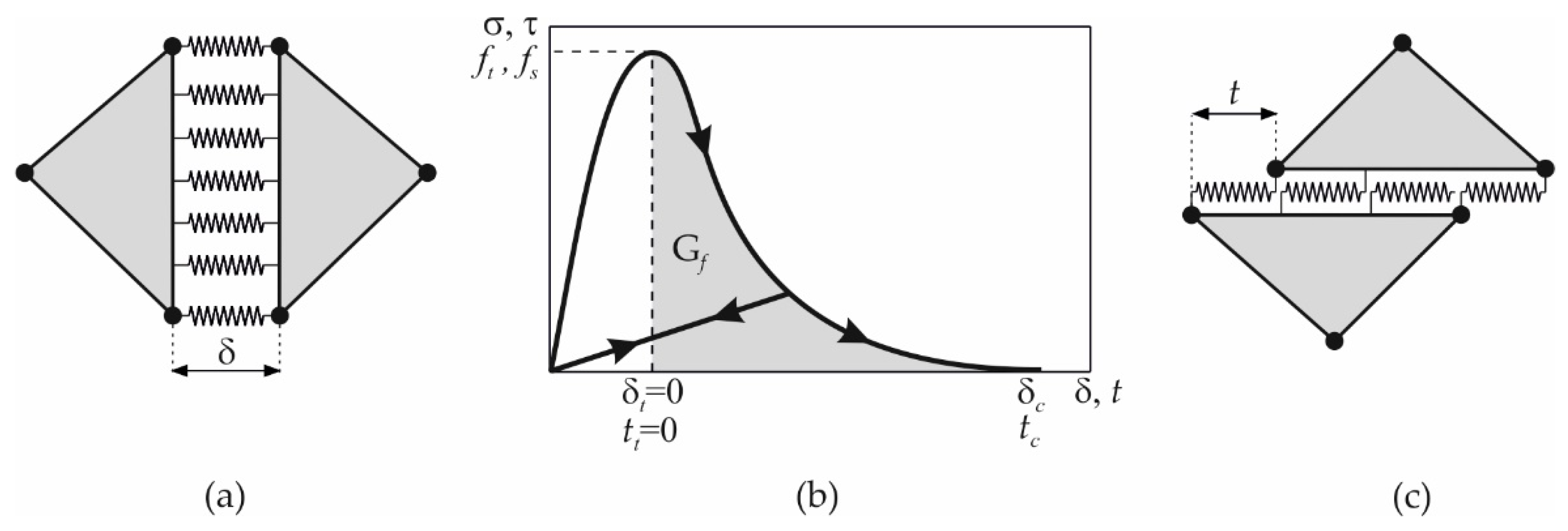
2. Fundamentals of FDEM

FDEM is intended for the dynamic simulation of discrete elements that can be found in mechanical interaction, due to which a discrete element can be fragmented into multiple elements through a fracture and fragmentation process. The main algorithms that enable numerical simulations in FDEM are contact detection, contact interaction, deformability of discrete elements, fracture and fragmentation and temporal integration of the equations of motion.
The contact detection algorithm aims to recognise pairs of discrete elements that are in contact. NBS (non-binary search) contact detection algorithm [37] is implemented in FDEM, where the number of searches is proportional to the total number of discrete elements.
The contact interaction algorithm aims to calculate the contact forces between two discrete elements in contact. When one discrete element penetrates the other, distributed potential contact forces arise between them based on the penalty function method [38]. Frictional forces caused by sliding are also considered in this algorithm [39].
The deformability of the discrete elements is enabled by discretising each discrete element with its own finite element mesh, which consists of three-noded triangular finite elements in 2D and four-noded tetrahedral finite elements in 3D [27]. The material constitutive law in the finite elements is linear viscoelastic [27].
The fracture and fragmentation algorithm aims to enable crack initiation and propagation through discrete elements. This is modelled with zero thickness contact elements implemented between the finite element mesh [40]. When two finite elements tend to separate in tension and/or shear as shown in Figure 1, tensile and/or shear stresses occur in the contact elements. The tensile stresses are a function of the separation δ, while the shear stresses are a function of the separation t. Before the tensile or shear strength is reached, normal separation δt and shear separation tt are theoretically equal to zero. In FDEM, this is achieved by using the penalty function method so that the axial separation δt and the shear separation tt tend towards zero as the penalty coefficient increases.
After reaching the tensile or shear strength of the material, the tensile stresses are given by:
σ = z f t
while shear stresses are given by:
τ = z f z
where z is the scaling function representing an approximation of the experimental stress–displacement curves [41]:
z = 1 a + b 1 a + b e D a + c b a + b 1 a b a 1 D + b 1 D c
with a = 0.63, b = 1.8 and c = 6.0, while the damage parameter D is given by:
D = D t 2 + D s 2
with
D t = ( δ δ t ) / ( δ c δ t ) ,   i f   δ t < δ < δ c 1 ,   i f   δ > δ c .
and
D s = ( t t s ) / ( t c t s ) ,   i f   t s < t < t c 1 ,   i f   t > t c
In FDEM, the mass of the discrete elements is concentrated in the nodes of the finite elements, while the temporal integration of the equations of motion is performed explicitly for each degree of freedom using the central difference time integration scheme [27].

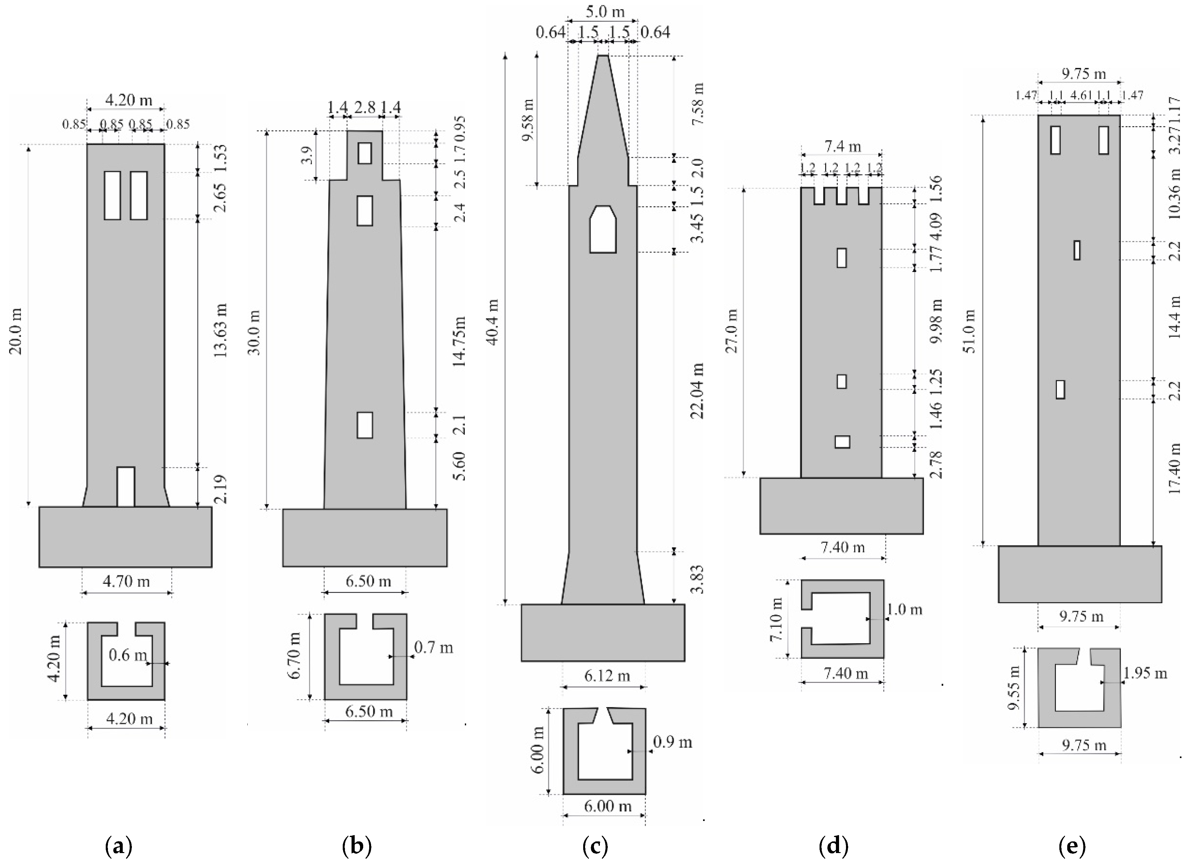
3. Description of the Structure and Retrofitting Technique

The geometric characteristics of the towers analysed in this paper were taken from the literature [36] and presented in Figure 2.
All towers are located in northern Italy and built of solid bricks with mortar joints between the twelfth and the eighteenth centuries. The main geometric characteristics of the towers, which relate to the tower height h, base width b, and slenderness h/b, are shown in Table 1.
Each of the towers was analysed for the case before retrofitting and after retrofitting. Since, due to the poor quality of the mortar before retrofitting, the connection between the towers and the foundation cannot ensure the transmission of tensile forces from the tower to the foundation, the towers before retrofitting were modelled as freely rested on the base, and the towers after retrofitting for the case that they are freely rested on a rigid base and the case that they are connected to a rigid base.
To date, numerous techniques have been developed for the retrofitting of masonry structures [33,35,42]. The aim of retrofitting is to increase their seismic resistance. There are three concepts for retrofitting masonry structures: reducing seismic forces, increasing the strength of the elements and improving by adding new structural elements.
The reduction in seismic forces includes base isolation and tuned mass dampers. Base isolation decouples the building from ground motion by adding flexible layers to the base that reduce the seismic forces transmitted to the structure. This method is not suitable for existing structures due to the complexity of implementation. Mass dampers are devices that are attached to the structure to absorb vibration energy and reduce the amplitude of vibrations caused by earthquakes. This technique may not be efficient because the seismic damper requires large deformations to be effective, while the masonry structure is generally rigid. In this way, the resistance to horizontal actions can be increased up to four times.
Increasing the strength of structural elements, which has a direct impact on increasing the seismic resistance of the entire structure, is the most commonly applied concept in the retrofitting of masonry structures. Within this concept, the retrofitting of historic masonry structures most often includes surface treatment, mortar joint treatment, internal treatment and the addition of new structural elements.
Surface treatment involves applying strengthening materials to one or both sides of structural elements and bonding them to the existing structure. The most commonly used strengthening materials are shotcrete, ferrocement and fibre-reinforced polymer (FRP). Shotcrete is applied by spraying shotcrete over a wire mesh installed on the surface of the masonry wall. Generally, the thickness of the layer is between 70 mm and 150 mm. To transfer shear forces, metal dowels are usually used to connect the shotcrete and masonry. In this way, the resistance to horizontal actions can be increased up to fourfold [43]. The ferrocement consists of several closely spaced layers of hardware mesh embedded in a high-strength (15–30 MPa) layer of cement mortar (10–15 mm thick). The mechanical properties of ferrocement depend on the properties of the mesh. In a static cyclic test [44], this retrofitting technique can increase the lateral resistance by one and a half times. Strengthening with FRP consists of a single or double-sided application of FRP in the form of strips or meshes fixed to the masonry structure with epoxy resins. FRP composites can increase the resistance to horizontal actions by up to three times [45]. With this approach, it is important to emphasise that the effectiveness of the retrofit is lost if the FRP begins to detach from the masonry surface. Mortar joint treatment consists of removing the worn mortar in the joints between the bricks and re-grouting with mortar with improved properties. This approach is usually combined with an internal treatment consisting of injecting a grout and filling the voids within the multi-layered masonry wall.
The addition of new structural elements usually consists of the addition of steel or reinforced concrete frames or grids or a reinforced concrete core within masonry structures to increase the load-bearing capacity for horizontal actions. In this case, the increase in lateral resistance has a significant impact on the dimensions and type of new structural elements.
In this study, the retrofitting of the towers is designed in such a way that all external walls were first grouted, and then injected in order to fill all cavities and connect the bulky internal core with the external layers. Finally, reinforced concrete core was constructed within the perimeter walls and connected to the masonry walls in the transverse direction with carbon ropes which are branched and fixed to the ends of the walls with epoxy resin. A schematic representation of the cross-section of the wall after retrofitting is shown in Figure 3.

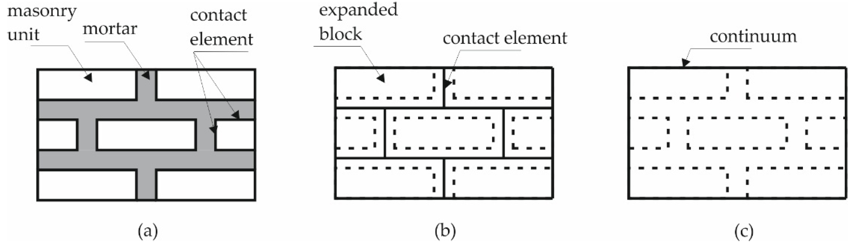
4. Modelling Strategy and Numerical Model

From the point of view of simplicity and accuracy, three levels of numerical modelling can be distinguished: micro-modelling, simplified micro-modelling and macro-modelling [13,46,47], as shown in Figure 4.
In detailed micro-modelling, the properties of mortar and masonry units are considered separately by discretising mortar and masonry with a separate finite element mesh, while the connection between mortar and masonry is modelled with zero-thickness contact elements. This approach is limited to small samples due to the extensive computational requirements. In simplified micro-modelling, the expanded block, which has the average properties of mortar and masonry unit, is modelled with its own finite element mesh, while the connection between mortar and block is modelled with contact elements of zero thickness, which also represent locations with potential cracks. This approach results in a loss of accuracy as the Poisson’s ratio of the mortar, which has a large influence on the compressive strength, is not taken into account. However, this difference is so small that it can be neglected [48,49]. The macro-modelling approach is most commonly used for modelling masonry structures due to its acceptable computational requirements [9,10,11,12,13,14,15,16,17,18]. In this approach, the masonry structure is considered as a composite material where the properties of the mortar and masonry units are homogenised and distributed throughout the masonry. However, macro-modelling can be used to accurately determine the stress distributions in masonry units and mortar [50,51]. In recent decades, many studies have been published on the experimental investigation of the behaviour of retrofitted masonry structures, but very few on their numerical modelling. When simulating retrofitted masonry, the original masonry element and the retrofitted masonry are usually modelled separately. However, due to the extensive computational requirements, this approach is limited to individual structural elements [52,53,54]. To investigate the behaviour of real retrofitted structures, the most commonly used approach is based on macro-modelling, where the original masonry structure and the strengthening material are modelled together as a homogeneous material with equivalent mechanical properties [55,56].
Within this study, a macro-modelling approach was adopted. Based on the computational requirements, a 2D numerical model was created. The choice of a 2D numerical model is justified by the fact that the towers have a relatively regular ground plan and that the presence of small openings, which disturb the regularity of the ground plan, will not significantly affect the out-of-plane behaviour of the structure. This approach based on a 2D numerical model was also adopted by Casolo et al. [36].
The towers were discretised with an irregular three-noded finite element mesh, which is shown in Figure 5.
The average length of the triangular finite element sides for all towers was approximately 0.20 m, which is consistent with the recommendations from the literature [9,28]. This finite element mesh density was found to be sufficiently accurate to reproduce the cracking pattern that occurred in a similar masonry tower after a seismic action [29]. The adopted finite element mesh density resulted with a total number of 5073, 5038, 5059, 5926, and 6496 finite elements for towers A, B, C, D and F, respectively.
The thickness of the central finite elements was twice the thickness of the wall, while the thickness of the edge elements corresponded to the length of the tower wall in the transversal direction. The material constitutive law in the finite elements was linear viscoelastic. Crack initiation and propagation in tension and shear was modelled using contact elements with zero thickness, which were implemented between the finite element mesh.
The material properties of the towers, before retrofitting, were adopted based on recommendations from the literature [29,36] and shown in Table 2.
The mechanical properties of the concrete and steel used to retrofit the towers were determined on the basis of recommendations from the literature [57] and are shown in Table 3.
The material properties of the towers after retrofitting are shown in Table 4. These properties are derived from the average material properties of an equivalent masonry wall with a thickness of one metre, in which the concrete core is 15 cm thick, and the cross-sectional area of steel in the reinforced concrete core is equal to 11.3 cm2/m.

5. Results of the Numerical Analyses and Discussion

In order to gain insight into the seismic resistance of the towers before and after retrofitting, each of the towers was subjected to the horizontal and vertical ground acceleration recorded during the 1979 Petrovac earthquake in Montenegro, whose amplitudes are shown as a function of time in Figure 6, while corresponding elastic acceleration response spectrum are shown in Figure 7. The amplitudes of the earthquake gradually increased until the structure collapsed. The collapse-inducing ground acceleration at which the structure collapsed was used as a measure of seismic resistance.
The collapse mechanism of masonry towers before retrofitting is shown in Figure 8. Taking into account the poor quality of the mortar, which cannot guarantee the transfer of tensile stresses from the tower to the foundation, it was assumed in these analyses that the towers rested freely on the foundation before retrofitting. Based on the conducted analyses, it can be seen that the towers with the assumed original material properties have a very low seismic resistance. In fact, for the observed seismic excitation, the collapse of the towers occurs on average at a collapse-inducing ground acceleration of 0.2 g. The results also show that all towers exhibit a quasi-brittle type of failure. Due to the stress concentration around the openings, cracks form and progressively spread over the entire tower, causing the collapse of the structure. Based on the presented results, it derives that when choosing a retrofitting technique for towers, special attention should be paid to the openings and their strengthening in order to avoid the occurrence of cracks around them or to prevent their propagation.
Figure 9 shows the failure pattern of retrofitted masonry towers which are fixed to the base with the corresponding collapse-inducing ground accelerations. From the presented results, it can be seen that in these towers no quasi-brittle failure occurs, as was the case in towers before retrofitting. However, as a result of the tensile load-bearing capacity being exceeded, a tensile crack forms above the base, which causes the complete separation of the upper part of the tower. In the performed analysis, the occurrence of these tensile cracks occurs at a collapse-inducing ground acceleration between 0.15 g and 0.30 g, where g is the gravitational constant corresponding to 9.81 m/s2. It is important to emphasise that in retrofitted masonry towers fixed to the base collapse-inducing ground accelerations does not lead to damage to the entire structure, but the damage is localised to the lower part of the tower. Although the structural failure has not yet appeared, due to the loss of connection between the base and the part of the tower above the crack, the maximum ground acceleration at which these cracks occurred is adopted as collapse-inducing ground acceleration.
Figure 10 shows the displacements of the top of the towers fixed to the base at the collapse-inducing ground accelerations during which a tensile crack occurs at the bottom, leading to a complete detachment of the upper part of the tower above the crack. From the presented results, it derives that as the height of the towers increases, the maximum amplitude of the displacement of the top of the towers also increases, ranging between 7.01 cm and 18.1 cm. The ratio between the maximum horizontal displacement of the tower top and the tower height in percentages for towers A, B, C, D and E is 0.42, 0.26, 0.41, 0.27 and 0.32, respectively, which is an average of 0.33 percent of the tower height.
In contrast to the towers that are fixed to the base, the towers resting freely on the base experience a rocking motion due to seismic activity, leading to much higher seismic resistance and horizontal displacements. Figure 11 shows the cracking pattern on the towers resting freely on an absolutely rigid base just before collapse-inducing ground accelerations agr. From the presented results, it derives that the ground accelerations just before collapse ranges between 0.35 g and 0.90 g. It can also be observed that small cracks appear at the bottom of the tower before the structure collapses, which are due to contact stresses caused by the impact between the structure and the base during the rocking motion.
Figure 12 shows the displacements of the top of the towers resting freely on the base at the collapse-inducing ground accelerations. Since the total displacement of the top of towers resting freely on the base is the sum of the displacements resulting from the rocking motion and the displacements resulting from the deformations of the towers, the component of the total displacement due to the rocking motion is marked in red. From the presented results, it derives that the displacement of the tower top of towers resting freely on the base is largely due to the rocking motion, and to a lesser extent to the deformation of the tower.
Based on the presented results, it can be observed that the towers resting freely on the base have significantly higher collapse-inducing ground accelerations. Table 5 shows a comparison of the collapse-inducing ground accelerations of towers fixed to the base, ag,max, and towers resting freely on the base, ag,max. The average value of the collapse-inducing ground acceleration of towers resting freely on a rigid base is 0.65 g, which is 2.7 times higher than the collapse-inducing ground acceleration leading to the failure of the connection of the towers fixed to an absolutely rigid base, i.e., exactly 0.24 g.
Based on the presented results, it can be observed that the structural behaviour of the towers fixed to the base is completely different from the behaviour of the towers resting freely on the base in an earthquake. In the case of the towers fixed to the base, the seismic energy introduced into the structure is converted into internal potential energy generated by elastic deformation of the structure. As a result, the structure collapses because it exceeds the strength of the material. In contrast, for the towers resting freely on the base, the seismic energy introduced into the structure is converted to a lesser extent into internal potential energy of the elastic deformations, and to a greater extent into kinetic energy of the rocking motion of the tower as confirmed in other studies [58,59,60]. Theoretically, if they had enough strength, the towers resting freely on the base would collapse by overturning. During the rocking motion caused by seismic excitation, the tower is subjected to inertial forces from the seismic action, which tend to rotate the tower around its edges, and gravitational forces, the resultant of which lies at the tower’s centre of gravity. As long as the horizontal displacements of the tower’s centre of gravity are small, the gravitational forces have a stabilising effect and attempt to return the tower to its equilibrium position. However, if the horizontal displacement of the tower becomes large, more precisely larger than half the width of the base of the tower, the gravitational forces become destabilising and cause the tower to tilt around its edge. This limited horizontal displacement of the tower’s centre of gravity, which is equal to half the width of the base, is referred to as δr,lim.
In the presented analyses, the tower never overturns because the strength of the material is exceeded due to the deformations that occur during the rocking motion.
Table 6 presents the comparison of the maximum total displacements, δmax, the maximum displacements due to the rocking motion, δr,max, and the limit rocking displacements, δr,lim, that would cause the tower to overturn due to the rocking motion, in relation to the tower height h. From the results shown, it derives that the average value of the maximum amplitude of the tower top displacements immediately before the collapse is 42.36 cm, which corresponds to an average of 1.45 per cent of the tower height. The maximum displacement of the tower top resulting from the rocking motion averages 87.2 per cent of the total displacement of the tower top. It can also be noted that the average maximum displacement of the tower top due to the rocking motion is 5.9 per cent of the limit displacement that would cause the structure to overturn, indicating that the stability reserve of the towers in terms of overturning is not even close to being reached.
In order to enable the rocking motion mechanism, and thus increase the seismic resistance of the towers resting freely on the base, it must be ensured that the stress concentrations occurring at the edges of the towers during rocking are lower than the permissible stresses. Assuming that the rotation of the towers around the edges occurs on a 10 cm wide contact surface, the value of the contact stress between the tower and the foundation is presented in Table 7. From the presented results, it can be observed that the contact stresses at the edge of the towers during rocking range from 7.4 MPa to 57.2 MPa, with an average value of 22.65 MPa. The authors propose to absorb these contact stresses by means of a reinforced concrete ring built around the entire perimeter of the lower edge of the tower. This reinforced concrete ring, which is shown in Figure 13, may have an approximate cross-sectional dimension of 40 cm/40 cm and be reinforced with longitudinal and transverse reinforcement; however, the actual dimensions of this ring as well as the associated reinforcement area need to be determined on a case-by-case basis.
Figure 14 shows the collapse mechanism of towers A, B, C, D and E, respectively, resting freely on an absolutely rigid base. From the results presented, it appears that the collapse of masonry towers resting freely on the foundation is mainly due to the propagation of cracks caused by splitting forces when the tower impacts the foundation as a result of rocking. These cracks gradually propagate in a vertical direction until the structure collapses completely. This is evident in towers B, C and D. The exception is tower A, where the tower cracks at the point of greatest structural weakness around the opening at the base of the tower, where the greatest stress concentrations are located. Furthermore, in tower E, in addition to the cracks due to the splitting forces, a horizontal tension crack also forms along the height of the tower due to the great height of the tower and the localised horizontal vibrations caused by the rocking.

6. Conclusions

In this paper, a series of numerical analyses were conducted to investigate the effect of boundary conditions on the seismic resistance of retrofitted ancient masonry towers which are not bounded by surrounding buildings. The following conclusions can be drawn from the results of the numerical analyses:
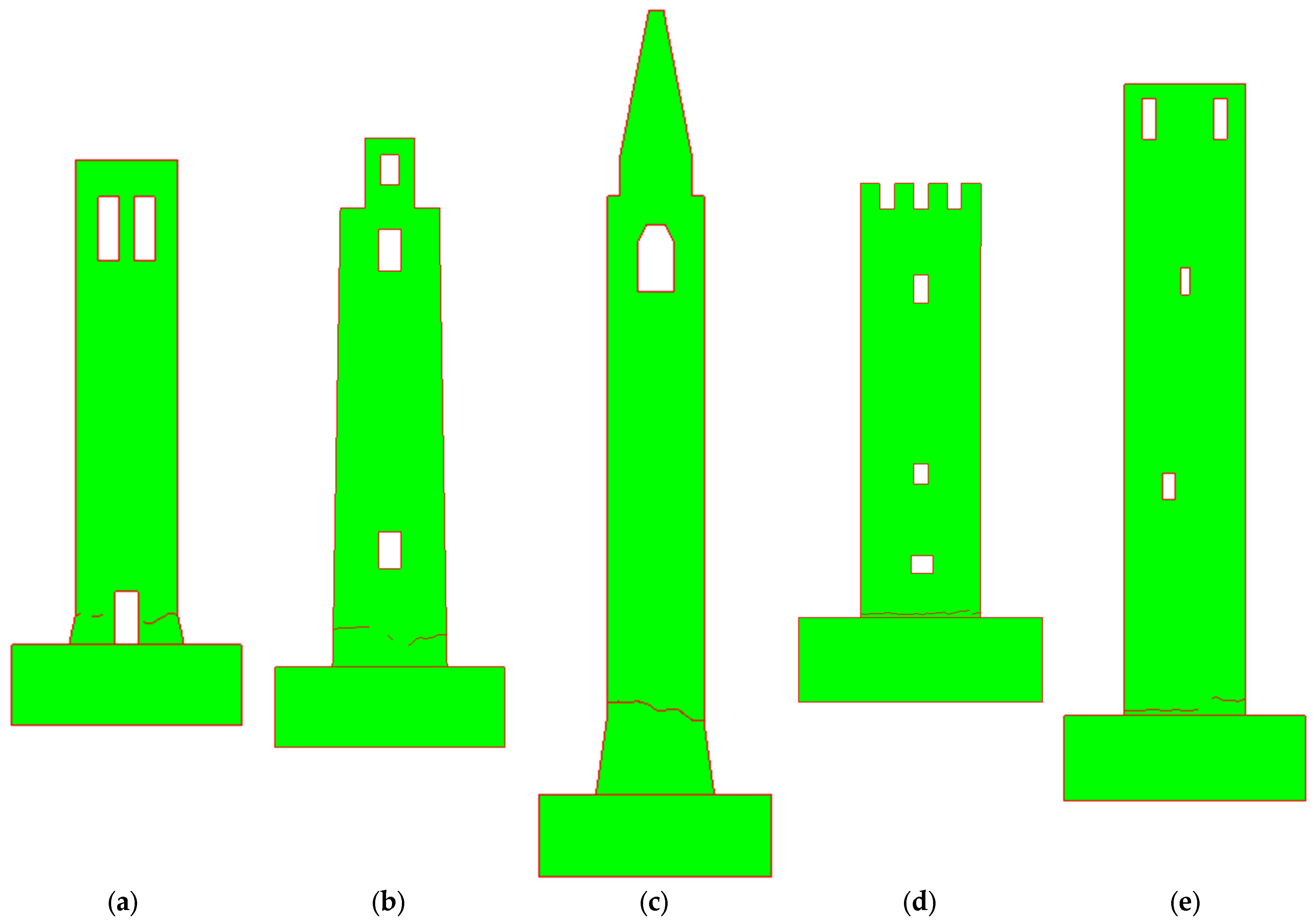
  • Towers with the assumed original material properties have a very low seismic resistance. For the observed seismic excitation, the collapse of the towers occurs on average at a collapse-inducing ground acceleration of 0.2 g. The results also show that all towers before retrofitting exhibit a quasi-brittle type of failure.
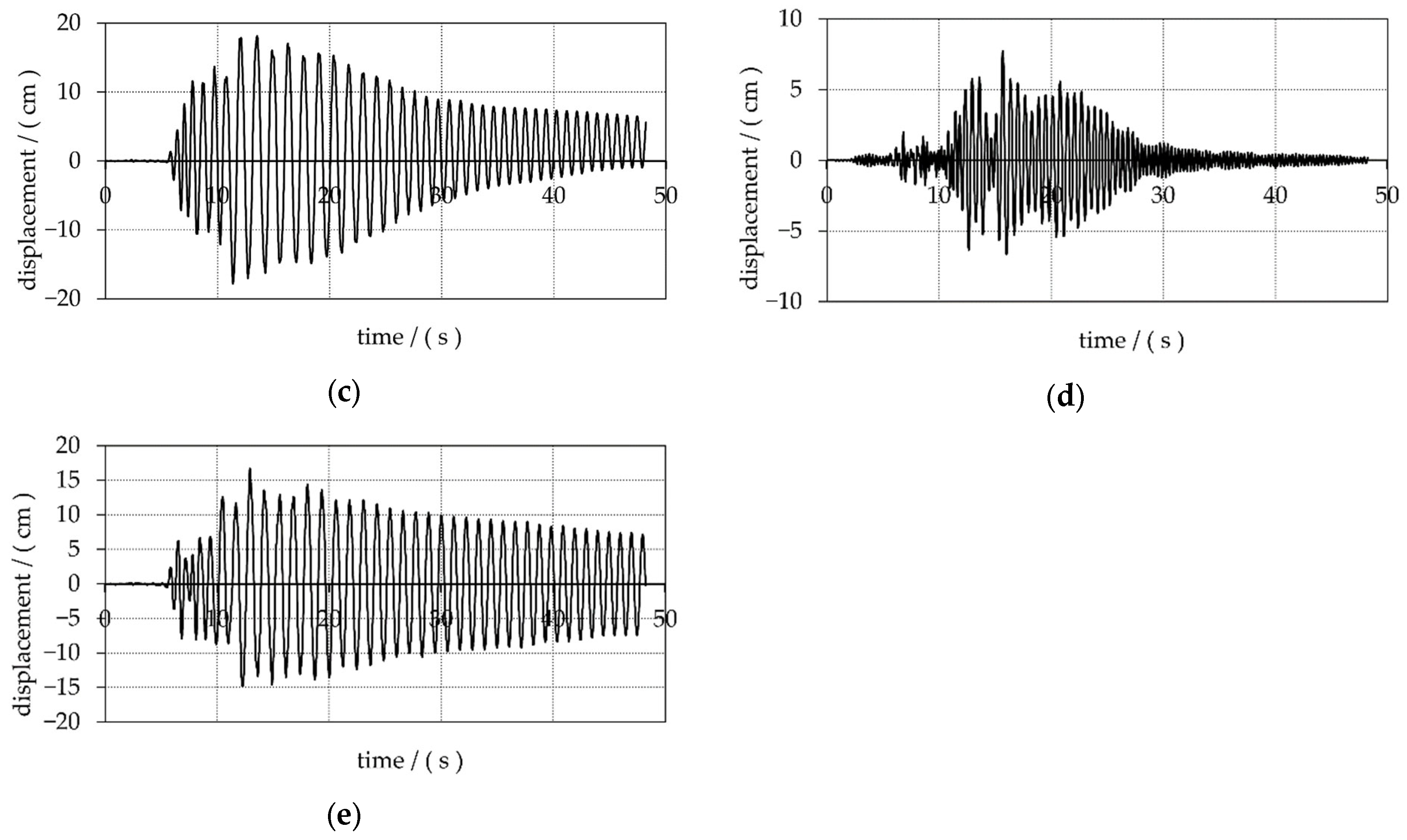
  • Under seismic activity, the structural behaviour of retrofitted towers fixed to the base is completely different from the behaviour of towers resting freely on the base.
  • In the case of towers fixed to the base, a significant part of the seismic energy introduced into the structure is converted into strain energy. This results in exceeding the tensile strength capacity immediately above the fixed connection to the base, which manifests itself in the form of a tensile crack across the entire width of the tower at an average collapse-inducing ground acceleration of 0.24 g.
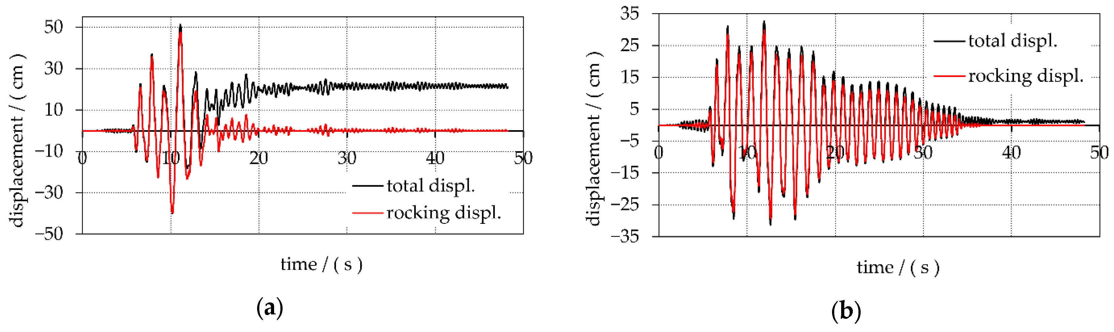
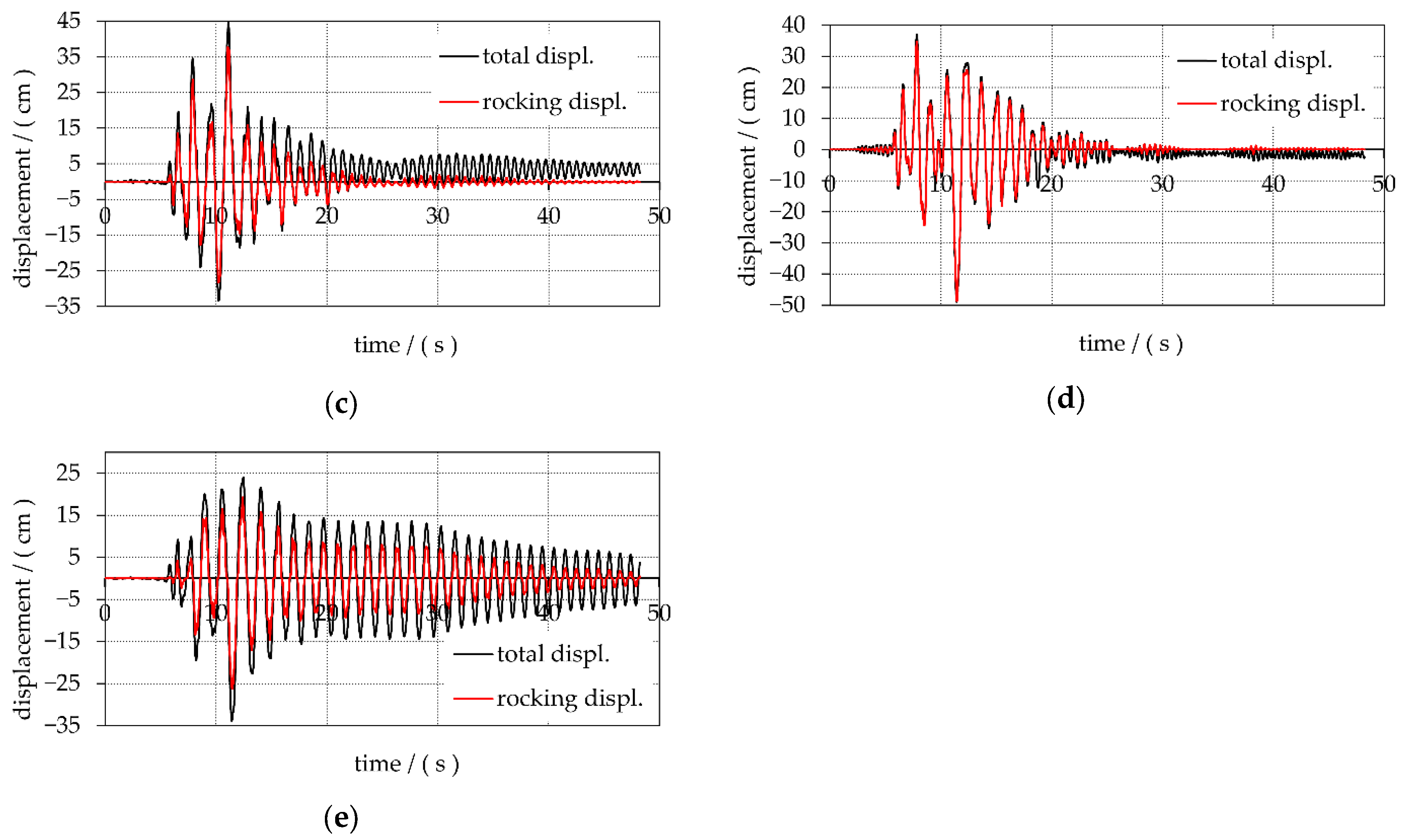
  • In the case of towers resting freely on the base, most of the seismic energy introduced into the structure is converted into kinetic energy by the rocking motion mechanism, and a smaller part into strain energy. This results in significantly lower stresses and higher seismic resistance for the freely resting towers compared to the towers fixed to the base. The average value of the collapse-inducing ground acceleration is 0.65 g, which is 2.7 times higher than the collapse-inducing ground acceleration of the towers fixed to the base.
  • In the case of retrofitted towers resting freely on the base, the maximum horizontal displacements of the tower tops that occur due to the rocking motion are on average 5.9 per cent of the limit displacements that would cause the towers to overturn. This indicates that the stability reserve of the towers in terms of overturning is not even close to being utilised.
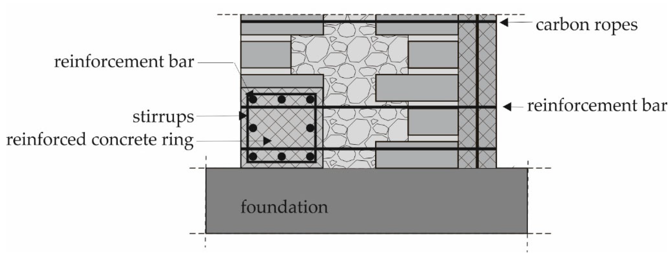
  • Assuming that the rocking motion of the towers around the edges occurs on a 10 cm wide contact surface, the contact stresses between the edges of the tower and the base range from 7.4 to 57.2 MPa, with an average value of 22.65 MPa. In order to prevent crushing of the material at the edges and to enable the rocking motion mechanism, it is proposed to construct a reinforced concrete ring around the entire circumference of the lower part of the towers resting freely on the base.
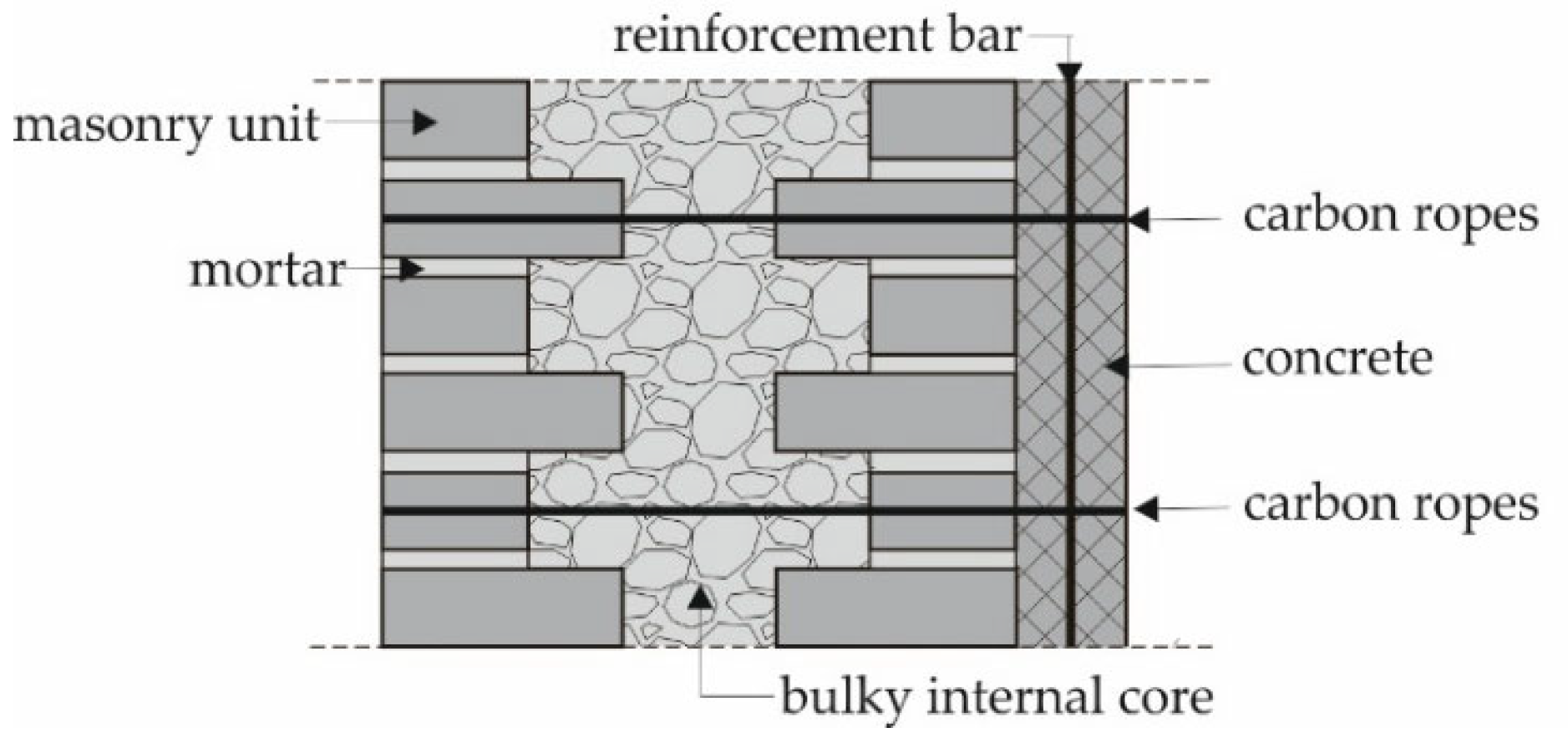
  • The assumed material properties of the towers obtained after their retrofitting by injecting the existing masonry structure, which was followed by constructing a reinforced concrete core inside the towers and connecting it to the original part of the structure with carbon ropes, are acceptable so that significant seismic resistance can be achieved for towers resting freely on the base. For a comprehensive assessment of seismic resistance, additional earthquake records need to be considered, which is beyond the scope of this paper.
The results of the numerical analyses indicate that when rehabilitating existing masonry towers or constructing new towers that are not bounded by neighbouring buildings, it is more effective to plan a freely resting connection of the tower to the foundation rather than a fixed connection which allows for a rocking motion mechanism. For further research, it would be interesting to analyse the behaviour of the towers on the elastic foundation and the behaviour of towers with the same geometry made of dry masonry and subjected to seismic loading.

Author Contributions

Conceptualisation, H.S., I.B. and N.Ž.; methodology, H.S., I.B. and N.Ž.; software, A.M.; validation, H.S., I.B. and N.Ž.; formal analysis, H.S., I.B. and N.Ž.; investigation, H.S., I.B. and N.Ž.; resources, H.S., I.B. and N.Ž.; data curation, H.S., I.B. and N.Ž.; writing—original draft preparation, H.S. and I.B.; writing—review and editing, N.Ž., B.T. and I.B.; visualisation, H.S., I.B. and N.Ž.; supervision, A.M.; project administration, B.T.; funding acquisition, H.S. All authors have read and agreed to the published version of the manuscript.

Funding

This research received no external funding.

Data Availability Statement

The authors confirm that the data supporting the findings of this study are available within the article.

Acknowledgments

This research is partially supported through the project KK.01.1.1.02.0027, which is co-funded by the Croatian Government and the European Union through the European Regional Development Fund—the Competitiveness and Cohesion Operational.

Conflicts of Interest

The authors declare no conflicts of interest.

References

  1. Işık, E.; Avcil, F.; Arkan, E.; Büyüksaraç, A.; İzol, R.; Topalan, M. Structural damage evaluation of mosques and minarets in Adıyaman due to the 6 February 2023 Kahramanmaraş earthquakes. Eng. Fail. Anal. 2023, 151, 107345. [Google Scholar] [CrossRef]
  2. Preciado, A.; Peña, F.; Fonseca, F.C.; Silva, C. Damage description and schematic crack propagation in Colonial Churches and old masonry buildings by the 2017 Puebla-Morelos earthquakes (Mw = 8.2 and 7.1). Eng. Fail. Anal. 2022, 141, 106706. [Google Scholar] [CrossRef]
  3. Lagomarsino, S. Damage assessment of churches after L’Aquila earthquake (2009). Bull. Earthq. Eng. 2012, 10, 73–92. [Google Scholar] [CrossRef]
  4. Acito, M.; Buzzetti, M.; Chesi, C.; Magrinelli, E.; Milani, G. Failures and damages of historical masonry structures induced by 2012 northern and 2016–17 central Italy seismic sequences: Critical issues and new perspectives towards seismic prevention. Eng. Fail. Anal. 2023, 49, 107257. [Google Scholar] [CrossRef]
  5. Atalić, J.; Uroš, M.; Šavor Novak, M.; Demšić, M.; Nastev, M. The Mw5.4 Zagreb (Croatia) earthquake of March 22, 2020: Impacts and response. Bull. Earthq. Eng. 2021, 19, 3461–3489. [Google Scholar] [CrossRef]
  6. Casolo, S. A three-dimensional model for vulnerability analysis of slender medieval masonry towers. J. Earthq. Eng. 1998, 2, 487–512. [Google Scholar] [CrossRef]
  7. Casolo, S.; Diana, V.; Uva, G. Influence of soil deformability on the seismic response of a masonry tower. Bull. Earthq. Eng. 2017, 15, 1991–2014. [Google Scholar] [CrossRef]
  8. Romero-Sánchez, E.; Requena-Garcia-Cruz, M.V.; Morales-Esteban, A. Impact of the soil-foundation-structure interaction in the seismic behaviour of a heritage masonry tower: The Giralda of Seville. Eng. Fail. Anal. 2024, 163, 108580. [Google Scholar] [CrossRef]
  9. Valente, M. Seismic vulnerability assessment and earthquake response of slender historical masonry bell towers in South-East Lombardia. Eng. Fail. Anal. 2021, 129, 05656. [Google Scholar] [CrossRef]
  10. Torelli, G.; D’Ayala, D.; Betti, M.; Bartoli, G. Analytical and numerical seismic assessment of heritage masonry towers. Bull. Earthq. Eng. 2020, 18, 969–1008. [Google Scholar] [CrossRef]
  11. Peña, F.; Lourenço, P.B.; Mendes, N.; Oliveira, D.V. Numerical models for the seismic assessment of an old masonry tower. Eng. Struct. 2010, 32, 1466–1478. [Google Scholar] [CrossRef]
  12. Preciado, A. Seismic vulnerability and failure modes simulation of ancient masonry towers by validated virtual finite element models. Eng. Fail. Anal. 2015, 57, 72–87. [Google Scholar] [CrossRef]
  13. Işık, E.; Harirchian, E.; Arkan, E.; Avcil, F.; Günay, M. Structural Analysis of Five Historical Minarets in Bitlis (Turkey). Buildings 2022, 12, 159. [Google Scholar] [CrossRef]
  14. Ubertini, F.; Cavalagli, N.; Kita, A.; Comanducci, G. Assessment of a monumental masonry bell-tower after 2016 Central Italy seismic sequence by long-term SHM. Bull. Earthq. Eng. 2018, 16, 775–801. [Google Scholar] [CrossRef]
  15. Shehu, R. Preliminary Assessment of the Seismic Vulnerability of Three Inclined Bell-towers in Ferrara, Italy. Int. J. Archit. Herit. 2020, 16, 485–517. [Google Scholar] [CrossRef]
  16. Valente, M. Earthquake response and damage patterns assessment of two historical masonry churches with bell tower. Eng. Fail. Anal. 2023, 151, m107418. [Google Scholar] [CrossRef]
  17. Magrinelli, E.; Acito, M.; Bocciarelli, M. Numerical insight on the interaction effects of a confined masonry tower. Eng. Struct. 2021, 237, 112195. [Google Scholar] [CrossRef]
  18. Castellazzi, G.; D’Altri, A.M.; de Miranda, S.; Chiozzi, A.; Tralli, A. Numerical insights on the seismic behavior of a non-isolated historical masonry tower. Bull. Earth. Eng. 2018, 16, 933–961. [Google Scholar] [CrossRef]
  19. Cundall, P.A. A Computer Model for Simulating Progressive Large Scale Movements in Blocky Rock Systems. In Proceedings of the Symposium of the International Society for Rock Mechanics, Nancy, France, 4–6 October 1971; International Society for Rock Mechanics (ISRM): Chambéry, France, 1971; p. II-8. [Google Scholar]
  20. Pulatsu, B.; Erdogmus, E.; Lourenço, P.B.; Lemos, J.V.; Tuncay, K. Simulation of the in-plane structural behavior of unreinforced masonry walls and buildings using DEM. Structures 2020, 27, 2274–2287. [Google Scholar] [CrossRef]
  21. Malomo, D.; DeJong, M.J.; Penna, A. Distinct element modelling of the in-plane cyclic response of URM walls subjected to shear-compression. Earthq. Eng. Struct. Dyn. 2019, 48, 1319–1428. [Google Scholar] [CrossRef]
  22. Galvez, F.; Sorrentino, L.; Dizhur, D.; Ingham, J.M. Using DEM to Investigate Boundary Conditions for Rocking URM Facades Subjected to Earthquake Motion. J. Struct. Eng. 2021, 147, 04021191. [Google Scholar] [CrossRef]
  23. Cundall, P.A. Formulation of a three-dimensional distinct element model—Part I: A scheme to detect and represent contacts in a system composed of many polyhedral blocks. Int. J. Rock Mech. Min. Sci. 1988, 25, 107–116. [Google Scholar] [CrossRef]
  24. Hart, R.D.; Cundall, P.A.; Lemos, J.V. Formulation of a three-dimensional distinct element model–Part II: Mechanical calculations. Int. J. Rock Mech. Min. Sci. 1988, 25, 117–125. [Google Scholar] [CrossRef]
  25. Kassotakis, N.; Sarhosis, S.; Riveiro, B.; Conde, B.; D’Altri, A.M.; Mills, J.; Milani, G.; de Miranda, S.; Castellazzi, G. Three-dimensional discrete element modelling of rubble masonry structures from dense point clouds. Autom. Constr. 2020, 119, 103365. [Google Scholar] [CrossRef]
  26. Malomo, D.; DeJong, M.J. A Macro-Distinct Element Model (M-DEM) for simulating in-plane/out-of-plane interaction and combined failure mechanisms of unreinforced masonry structures. Earthq. Eng. Struct. Dyn. 2022, 51, 793–811. [Google Scholar] [CrossRef]
  27. Munjiza, A. The Combined Finite-Discrete Element Method; John Wiley & Sons: Oxford, UK, 2004. [Google Scholar]
  28. Živaljić, N.; Balić, I.; Smoljanović, H.; Munjiza, A. Seismic Analysis of Historical Masonry Towers with Different Support Conditions. Int. J. Archit. Herit. 2024, 19, 1421–1439. [Google Scholar] [CrossRef]
  29. Balić, I.; Smoljanović, H.; Trogrlić, B.; Munjiza, A. Seismic Analysis of the Bell Tower of the Church of St. Francis of Assisi on Kaptol in Zagreb by Combined Finite-Discrete Element Method. Buildings 2021, 11, 373. [Google Scholar] [CrossRef]
  30. Smoljanović, H.; Nikolić, Ž.; Živaljić, N. A combined finite–discrete numerical mod-el for analysis of masonry structures. Eng. Fract. Mech. 2015, 136, 1–14. [Google Scholar] [CrossRef]
  31. Smoljanović, H.; Živaljić, N.; Nikolić, Ž. A combined finite-discrete element analysis of dry stone masonry structures. Eng. Struct. 2013, 52, 89–100. [Google Scholar] [CrossRef]
  32. Przewłócki, I.; Dardzińska, I.; Świniański, J. Review of historical buildings’ foundations. Géotechnique 2005, 55, 363–372. [Google Scholar] [CrossRef]
  33. Yadav, P.; Khursheed, S.; Solanki, S.K.; Paul, V.K. A Review of Retrofitting Techniques of Masonry Structures. Int. J. Multidisc. Innov. Res. 2022, 2, 12–20. [Google Scholar]
  34. Zucca, M.; Reccia, E.; Longarini, N.; Cazzani, A. Seismic Assessment and Retrofitting of an Historical Masonry Building Damaged during the 2016 Centro Italia Seismic Event. Appl. Sci. 2022, 12, 11789. [Google Scholar] [CrossRef]
  35. Wang, C.; Sarhosis, V.; Nikitas, N. Strengthening/retrofitting techniques on unreinforced masonry structure/element subjected to seismic loads: A literature review. Open Constr. Build. Techn. J. 2018, 12, 251–268. [Google Scholar] [CrossRef]
  36. Casolo, S.; Milani, G.; Uva, G.; Alessandri, C. Comparative seismic vulnerability analysis on ten masonry towers in the coastal Po Valley in Italy. Eng. Struct. 2013, 49, 465–490. [Google Scholar] [CrossRef]
  37. Munjiza, A.; Andrews, K.R.F. NBS contact detection algorithm for bodies of similar size. Int. J. Numer. Methods Eng. 1998, 43, 131–149. [Google Scholar] [CrossRef]
  38. Munjiza, A.; Andrews, K.R.F. Penalty function method for combined finite-discrete element system comprising large number of separate bodies. Int. J. Numer. Methods Eng. 2000, 49, 1377–1396. [Google Scholar] [CrossRef]
  39. Smoljanović, H.; Živaljić, N.; Nikolić, Ž.; Munjiza, A. Numerical analysis of 3D dry-stone masonry structures by combined finite-discrete element method. Int. J. Sol. Struct. 2018, 136–137, 150–167. [Google Scholar] [CrossRef]
  40. Munjiza, A.; Andrews, K.R.F.; White, J.K. Combined single and smeared crack model in combined finite-discrete element method. Int. J. Numer. Methods Eng. 1999, 44, 41–57. [Google Scholar] [CrossRef]
  41. Hordijk, D.A. Tensile and tensile fatigue behaviour of concrete—Experiments, modelling and analyses. Heron 1992, 37, 3–79. [Google Scholar]
  42. Keshmiry, A.; Hassani, S.; Dackermann, U.; Li, J. Assessment, repair, and retrofitting of masonry structures: A comprehensive review. Constr. Build. Mater. 2024, 442, 137380. [Google Scholar] [CrossRef]
  43. ElGawady, M.A.; Lestuzzi, P.; Badoux, M. Retrofitting of masonry walls using shotcrete. In Proceedings of the 2006 NZSEE Conference Proceedings, Napier, New Zealand, 10–12 March 2006; p. 45. [Google Scholar]
  44. Vasconcelos, G.; Mora, J.; Fangueiro, R.; Cunha, F.E.; Martins, A. Flexural behavior of brick masonry retrofitted with braided textile meshes. In Proceedings of the 4th International Conference on Integrity, Reliability and Failure (IRF2013), Funchal, Portugal, 23–27 June 2013; p. 4091. [Google Scholar]
  45. Mahmood, H.; Ingham, J.M. Diagonal Compression Testing of FRP-Retrofitted Unreinforced Clay Brick Masonry Wallette’s. J. Compos. Constr. 2011, 15, 810–820. [Google Scholar] [CrossRef]
  46. Lourenço, P.B. Computational Strategies for Masonry Structures. Ph.D. Thesis, Delft University of Technology, Delft, The Netherlands, 1996. [Google Scholar]
  47. Işık, E.; Avcil, F.; Harirchian, E.; Arkan, E.; Bilgin, H.; Özmen, H.B. Architectural Characteristics and Seismic Vulnerability Assessment of a Historical Masonry Minaret under Different Seismic Risks and Probabilities of Exceedance. Buildings 2022, 12, 1200. [Google Scholar] [CrossRef]
  48. Lourenco, P.B. An Orthotropic Continuum Model for the Analysis of Masonry Structures; Report, No.03-21-1-31-27; Delft University of Technology: Delft, The Netherlands, 1995. [Google Scholar] [CrossRef]
  49. Lee, J.S.; Pande, G.N.; Middleton, J.; Kralj, B. Numerical modelling of brick masonry panels subject to lateral loadings. Comput. Struct. 1996, 61, 735–745. [Google Scholar] [CrossRef]
  50. Pande, G.N.; Liang, J.X.; Middleton, J. Equivalent elastic moduli for brick masonry. Comput. Geotech. 1989, 8, 243–265. [Google Scholar] [CrossRef]
  51. Lourenco, P.B.; Rots, J.G.; Blaauwendraad, J. Two approaches for the analysis of masonry structures: Micro and macro-modeling. Heron 1995, 40, 313–340. [Google Scholar]
  52. Maruccio, C.; Basilio, I.; Oliveira, D.V.; Lourenço, P.B.; Giorgio Monti, G. Numerical modelling and parametric analysis of bond strength of masonry members retrofitted with FRP. Constr. Build. Mater. 2014, 73, 713–727. [Google Scholar] [CrossRef]
  53. Malena, M.; Focacci, F.; Carloni, C.; de Felice, G. The effect of the shape of the cohesive material law on the stress transfer at the FRP-masonry interface. Compos. Part B Eng. 2017, 110, 368–380. [Google Scholar] [CrossRef]
  54. Hussain, M.; Peng, B. Numerical simulation to investigate the performance of existing masonry walls strengthened by ultra high performance concrete layer. J. Umm Al-Qura Univ. Eng. Archit 2025. [Google Scholar] [CrossRef]
  55. Gupta, T.; Dubey, K.; Panwar, G.; Singh, S. Numerical Modeling of Retrofitted Structures. In Proceedings of the 2020 International Conference on Intelligent Engineering and Management (ICIEM 2020), London, UK, 17–19 June 2020; IEEE: Piscataway, NJ, USA, 2020; pp. 431–436. [Google Scholar]
  56. Božulić, I.; Vanin, F.; Beyer, K. Numerical Modeling of FRP-Strengthened Masonry Structures Using Equivalent Frame Models. In Structural Analysis of Historical Constructions; SAHC 2023–Vol. 2; RILEM Bookseries; Endo, Y., Hanazato, T., Eds.; Springer: Berlin/Heidelberg, Germany, 2024. [Google Scholar] [CrossRef]
  57. Maekawa, K.; Okamura, H.; Pimanmas, A. Non-Linear Mechanics of Reinforced Concrete, 1st ed.; CRC Press: Boca Raton, FL, USA, 2003. [Google Scholar] [CrossRef]
  58. Yim, C.-S.; Chopra, A.K.; Penzien, J. Rocking response of rigid blocks to earthquakes. Earthq. Eng. Struct. Dyn. 1980, 8, 565–587. [Google Scholar] [CrossRef]
  59. Peña, F.; Prieto, F.; Lourenço, P.B.; Campos Costa, A.; Lemos, J.V. On the dynamics of rocking motion of single rigid-block structures. Earthq. Eng. Struct. Dyn. 2007, 36, 2383–2399. [Google Scholar] [CrossRef]
  60. Thonstad, T.; Mantawy, I.; Stanton, J.; Eberhard, M.O.; Sanders, D. Shaking Table Performance of a New Bridge System with Pretensioned Rocking Columns. J. Bridge Eng. 2016, 21, 1–14. [Google Scholar] [CrossRef]
Figure 1. (a) Normal spring; (b) strain softening defined in terms of displacement; (c) shear spring.
Buildings 15 02495 g001
Figure 2. Geometric characteristics of the numerical models for the towers: (a) A; (b) B; (c) C; (d) D; (e) E.
Buildings 15 02495 g002
Figure 3. Cross-section of the masonry wall after adopted retrofitting.
Buildings 15 02495 g003
Figure 4. Computational strategies for modelling masonry structures (a) detailed micro-modelling; (b) simplified micro-modelling; (c) macro-modelling.
Buildings 15 02495 g004
Figure 5. Finite element meshes of the towers: (a) A; (b) B; (c) C; (d) D; (e) E.
Buildings 15 02495 g005
Figure 6. Accelerograms of the Petrovac earthquake (15 April 1979): (a) horizontal component; (b) vertical component.
Buildings 15 02495 g006
Figure 7. Elastic acceleration response spectrum of the Petrovac earthquake (15 April 1979) for: (a) horizontal component; (b) vertical component.
Buildings 15 02495 g007
Figure 8. Crack patterns of towers resting freely on an absolutely rigid base for: (a) tower A and agr = 0.20 g; (b) tower B and agr = 0.20 g; (c) tower C and agr = 0.15 g; (d) tower D and agr = 0.25 g; (e) tower E and agr = 0.15 g.
Buildings 15 02495 g008
Figure 9. Crack pattern of towers fixed to an absolutely rigid base for: (a) tower A and agr = 0.30 g; (b) tower B and agr = 0.25 g; (c) tower C and agr = 0.15 g; (d) tower D and agr = 0.25 g; (e) tower E and agr = 0.25 g.
Buildings 15 02495 g009
Figure 10. Displacements of the top of the towers fixed to the base for: (a) tower A and agr = 0.30 g; (b) tower B and agr = 0.25 g; (c) tower C and agr = 0.15 g; (d) tower D and agr = 0.25 g; (e) tower E and agr = 0.25 g.
Buildings 15 02495 g010aBuildings 15 02495 g010b
Figure 11. Crack pattern of the towers resting freely on an absolutely rigid base for: (a) tower A and agr = 0.70 g; (b) tower B and agr = 0.70 g; (c) tower C and agr = 0.60 g; (d) tower D and agr = 0.90 g; (e) tower E and agr = 0.35 g.
Buildings 15 02495 g011
Figure 12. Displacements of the top of the towers resting freely on the base for: (a) tower A and agr = 0.70 g; (b) tower B and agr = 0.70 g; (c) tower C and agr = 0.60 g; (d) tower D and agr = 0.90 g; (e) tower E and agr = 0.35 g.
Buildings 15 02495 g012aBuildings 15 02495 g012b
Figure 13. Cross-section of the masonry wall after adopted retrofitting.
Buildings 15 02495 g013
Figure 14. Collapse mechanisms of towers resting freely on an absolutely rigid base for: (a) tower A and agr = 0.80 g; (b) tower B and agr = 0.80 g; (c) tower C and agr = 0.70 g; (d) tower D and agr = 1.00 g; (e) tower E and agr = 0.40 g.
Buildings 15 02495 g014
Table 1. The main geometric characteristics of the towers.
TowerABCDE
height of the tower, h/(m)20.0030.0040.4027.0051.00
base width of the tower, b/(m)4.706.506.127.409.75
slenderness h/b4.25
0.670
4.626.533.645.23
Table 2. Adopted mechanical properties of the masonry before retrofitting.
Material Properties
Modulus of elasticity, E (MPa)2250
Poisson’s ratio, ν0.30
0.670
Tensile strength, ft (MPa)0.27
Shear strength, fs (MPa)1.09
Fracture energy in tension Gf,t (N/m)35
Fracture energy in shear Gf,s (N/m)140
Friction coefficient, µ0.70
Unit mass, ρ (kg/m3)1700
Table 3. Mechanical properties of concrete and steel used for the retrofitting of the towers.
Material PropertiesConcreteSteel
Modulus of elasticity, E (MPa)33,000210,000
Poisson’s ratio, ν0.20
0.670
0.20
Tensile strength, ft (MPa)3.00560
Shear strength, fs (MPa)12.0392
Fracture energy in tension Gf,t (N/m)4002,300,000
Fracture energy in shear Gf,s (N/m)16001,610,000
Friction coefficient, µ0.700.70
Unit mass, ρ (kg/m3)25007850
Table 4. Adopted mechanical properties of the retrofitted masonry.
Material Properties
Modulus of elasticity, E (MPa)6625
Poisson’s ratio, ν0.3
0.670
Tensile strength, ft (MPa)1.17
Shear strength, fs (MPa)2.89
Fracture energy in tension Gf,t (N/m)2340
Fracture energy in shear Gf,s (N/m)1910
Friction coefficient, µ0.70
Unit mass, ρ (kg/m3)1800
Table 5. Comparison of the collapse-inducing ground accelerations, ag,max for the towers resting freely on the base and the towers fixed to the base.
Boundary Condition/TowerABCDE
fixed to the base, ag,max/(g)0.30
0.670
0.250.150.250.25
resting freely on the base, ag,max/(g)0.700.700.600.900.35
ag,max (resting freely)/ag,max (fix to the base)2.32.84.03.61.4
Table 6. Comparison of the maximum total displacements, δmax, the maximum displacements due to the rocking motion, δr,max, and the limit rocking displacements, δr,lim, for the towers resting freely on the base.
TowerABCDE
max. total displacement, δmax/(cm)51.3
0.670
32.645.049.033.9
(δmax/h) 1002.571.091.111.810.66
max. rocking displacement, δr,max/(cm)47.629.837.844.826.2
(δr,max/h) 1002.380.990.941.660.51
(δr,max/δmax)·1009391849177
limit rocking displ., δr,lim/(cm)470650612740975
(δr,max/δr,lim)·10010.14.56.26.02.6
Table 7. The value of the contact stress at the edges of freely resting towers during rocking with an assumed contact surface width of 10 cm.
TowerABCDE
weight of the tower, W/(MN)3.118.1911.5712.4455.85
width of the base/(m)4.26.56.07.49.75
contact stress/(MPa)7.4012.619.2816.8157.2
Disclaimer/Publisher’s Note: The statements, opinions and data contained in all publications are solely those of the individual author(s) and contributor(s) and not of MDPI and/or the editor(s). MDPI and/or the editor(s) disclaim responsibility for any injury to people or property resulting from any ideas, methods, instructions or products referred to in the content.

