Article

Robustness of Steel Moment-Resisting Frames Under Column Loss Scenarios with and without Prior Seismic Damage

1
Department of Structures for Engineering and Architecture, University of Naples Federico II, 80134 Napoli, Italy
2
Subsea7, L-1471 Luxembourg, Luxembourg
*
Author to whom correspondence should be addressed.
Buildings 2025, 15(14), 2490; https://doi.org/10.3390/buildings15142490
Submission received: 26 May 2025 / Revised: 26 June 2025 / Accepted: 8 July 2025 / Published: 16 July 2025
(This article belongs to the Special Issue Advanced Research on Seismic Performance of Steel Structures)

Abstract

This study investigates the robustness of steel moment-resisting frames (MRFs) under column loss scenarios, both in undamaged and post-seismic conditions. In this context, robustness is defined as the ability of a damaged structure to prevent progressive collapse following an earthquake. A parametric investigation was conducted on 48 three-dimensional MRF configurations, varying key design and geometric parameters such as the number of storeys, span length, and design load combinations. Nonlinear dynamic analyses were performed using realistic ground motions and column loss scenarios defined by UFC guidelines. The effects of pre-existing seismic damage, façade claddings, and joint typologies were explicitly accounted for using validated component-based modelling approaches. The results indicate that long-span, low-rise frames are more vulnerable to collapse initiation due to higher plastic demands, while higher-rise frames benefit from load redistribution through their increased redundancy. In detail, long-span, low-rise frames experience roughly ten times higher displacement demands than their short-span counterparts, and post-seismic damage has limited influence, yielding rotational demands within 5–10% of the undamaged case. The Reserve Displacement Ductility (RDR) ranges from approximately 6.3 for low-rise, long-span frames to 21.5 for high-rise frames, highlighting the significant role of geometry in post-seismic robustness. The post-seismic damage was found to have a limited influence on the dynamic displacement and rotational demands, suggesting that the robustness of steel MRFs after a moderate earthquake is largely comparable to that of the initially undamaged structure. These findings support the development of more accurate design and retrofit provisions for seismic and multi-hazard scenarios.

1. Introduction

Steel moment-resisting frames (MRFs) are widely used in seismic-prone regions due to their ductility, energy dissipation capacity, and ability to withstand large deformations without experiencing catastrophic failure. However, the robustness of these structures after seismic events remains a critical aspect that influences their residual performance and safety.
Post-seismic robustness refers to the ability of an MRF to resist progressive collapse following an initial damage state induced by an earthquake. Current design approaches for structural robustness typically assume undamaged conditions, neglecting the potential degradation caused by seismic actions [1]. However, real-world scenarios indicate that structures sustaining moderate to severe seismic damage may become more vulnerable to progressive collapse, especially in the presence of additional extreme events such as gas explosions, fires, or accidental column removal [2]. Understanding the post-seismic robustness of MRFs is essential for ensuring life safety, structural reliability, and resilience in the aftermath of an earthquake.
Various studies have highlighted the role of redundancy, energy dissipation, and load redistribution in preventing progressive collapse [3,4,5,6,7]. Robustness evaluation methods include nonlinear static and dynamic analyses, which simulate column loss scenarios to assess the redistribution capacity of the structure [4].
More recent works have further deepened the understanding of MRF robustness, including probabilistic approaches [8], European guidance on structural robustness [9], and machine learning-based assessments of nonlinear response [10].
Previous research indicates that MRFs primarily fail due to the loss of lateral resistance and excessive plastic hinge formation, leading to progressive collapse [6]. The behaviour of beam-to-column connections, especially flush end-plate joints, significantly influences the overall robustness of MRFs under extreme conditions [7]. Zhang et al. [11] demonstrated that bolted angle connections can develop substantial tensile resistance and large deformation capacity under monotonic loading. Although their study focused on uniaxial tensile tests, these characteristics suggest a potential for such connections to contribute to load transfer mechanisms in extreme scenarios, such as column removal.
Seismic loading introduces residual deformations and reduces the capacity of key structural elements, likely leading to a weakened post-seismic state [12]. Studies have shown that damage accumulation in beam-to-column joints and column bases significantly affects the ability of structures to resist additional loading scenarios, such as column loss [13]. The presence of residual drift and cracks in steel connections can exacerbate instability and reduce energy absorption capacity [14].
Design codes, such as the Eurocode and the Unified Facilities Criteria [15,16], offer general guidelines for progressive collapse prevention but do not explicitly address post-seismic conditions. Research has indicated that current seismic detailing requirements may not be sufficient to ensure adequate robustness after an earthquake, necessitating additional reinforcement strategies [14].
Innovative structural systems such as steel frames combined with rocking shear walls have shown promising seismic and post-seismic performance by enhancing energy dissipation and limiting residual damage, thus contributing to overall structural robustness under sequential extreme events [17].
Non-structural components, particularly façade claddings and partition walls, have been found to contribute significantly to the robustness of steel frames. While traditionally disregarded in collapse analyses, recent experimental and numerical studies suggest that these elements provide additional lateral support and energy dissipation, enhancing the structural response to progressive collapse scenarios [18,19].
Despite the extensive literature on seismic design and progressive collapse separately, limited attention has been paid to the interaction between post-seismic damage and robustness against column loss. Furthermore, very few studies account for the detailed contribution of joints and non-structural elements in such scenarios, which this study addresses explicitly.
In light of these considerations, this study aims to investigate the post-seismic robustness of steel moment-resisting frames in both undamaged and seismically damaged conditions; for this purpose, nonlinear dynamic analyses were performed on a set of 3D MRF structures subjected to column loss and post-seismic column loss scenarios. Specifically, the pursuit of the following objectives has guided the research:
  • To evaluate the robustness of steel MRFs by using a refined model strategy (3D model accounting for the contribution of joints and claddings).
  • To focus on the eventual impact of seismic damage on the ability of MRFs to resist progressive collapse.
  • To identify key structural parameters influencing post-seismic robustness, including the number of storeys, span lengths, column loss scenario, etc.
  • To assess the contribution of secondary structural elements and non-structural components, such as façade claddings, in preventing collapse propagation.
Accordingly, the paper is structured as follows: (i) Section 2 describes the parametric study, including the variation parameters and structural design; (ii) Section 3 outlines the modelling assumptions and analysis methodology; (iii) Section 4 presents the results for both initially undamaged and post-seismic scenarios; and (iv) Section 5 concludes with the main findings and implications.

2. Parametric Study

The numerical study was designed as a full-factorial parametric investigation involving 48 distinct three-dimensional MRF configurations. These configurations were systematically derived by varying a selected set of structural and design parameters, including the number of storeys, interstorey height, bay span, cladding type, plan layout, and lateral load design conditions, as summarised in Table 1.

2.1. Parameters of Variation

A set of 48 3D buildings equipped with moment-resisting frames was designed by varying (i) the number of storeys, (ii) the interstorey height, (iii) the span length, (iv) the bay configuration, and (v) the designed lateral loads (either wind or wind + earthquake).
The parameters of variation are summarised in Table 1 with the relevant admissible values.
Each structure is equipped with two MRFs per direction (see Figure 1a), located on the perimeter; the remaining frames are designed to resist gravity loads only.
To unequivocally identify each structure, a labelling system was created, thus establishing the correspondence between the structure’s name and its unique set of parametric variables. An example of a structure label is given by the code N8-H3-S6-CL-T4x4-DE, where N indicates the number of storeys, H is the interstorey height, S is the bay span, C is the cladding type, T is the type of bay plan layout, and D is the lateral force design scenario.
The structures designed were then analysed under different column loss scenarios, for both undamaged and damaged conditions, where the latter corresponds to the structure after sustaining damage induced by seismic action. Regarding the column loss location, three different peripheral scenarios have been considered, as shown in Figure 1b, with column removals defined in accordance with the UFC 2009 [20], namely, for the corner column, long-façade column, and short-façade column. The section of the column to be removed is the one defined between the ground level and the first storey for all considered scenarios.

2.2. Design Assumptions

The frames to be analysed were designed according to Eurocodes. EN 1991-1-7 [21] was applied to determine the design actions and the loading combination; the verification checks are compliant with EN 1993-1-1 [22] and EN 1998 [15].
For the loading scenario DE (wind + earthquake), the structures were designed according to capacity design criteria compliant with EC8 to guarantee a weak beam–strong column mechanism type; conversely, for loading scenario DW (wind), no hierarchy of resistances was considered, structural members were designed to fulfil all limit states according to EC3, and a strong beam–weak column failure type was obtained.
The considered gravity loads are summarised in Table 2.
For the determination of the design wind loads, the basic wind velocity vb was calculated through the expression given in clause 4.2(2)P of the EN 1991-1-4 [23]. In the fundamental value of the basic wind velocity, vb,0 is assumed to be equal to 30 m/s; terrain category III is considered, which is representative of suburban areas. This implies moderate wind action; indeed, designing against strong wind action could lead to highly robust MRFs, not representative of buildings in European urban areas. The seismic action was defined according to Eurocode 8, and the following base hypotheses were assumed:
  • Seismic action Type 1 (agR = 2.45 ms2) and Type 2 (agR = 2.45 ms2);
  • Soil type C;
  • Importance class II;
  • Ductility class DCH;
  • Behaviour factor q = 5 × (au/a1) = 5 × 1.3 = 6.5.
The reference ground acceleration values used correspond to an acceleration of 0.25 g, which was deemed representative of moderate-seismicity zones. IPE and HE profiles were used for beams; HE was used for the columns. The cross sections of all steel members (i.e., beams, bracings, and columns) were selected to satisfy the Class 1 requirements according to EN 1993:1-1 [22].
The beam-to-column joints of MRFs are end-plate bolted joints with rib-stiffeners and supplementary web plates [24], while flush end-plate joints were designed for the gravity frames; both were designed according to EN 1993 and EN 1998. For gravity frame beam-to-beam joints, the web cleat typology was selected, given that it is widely adopted by designers, due to its low cost and reduced assembly time.

3. Robustness Performance Evaluation

3.1. Analysis Methodology

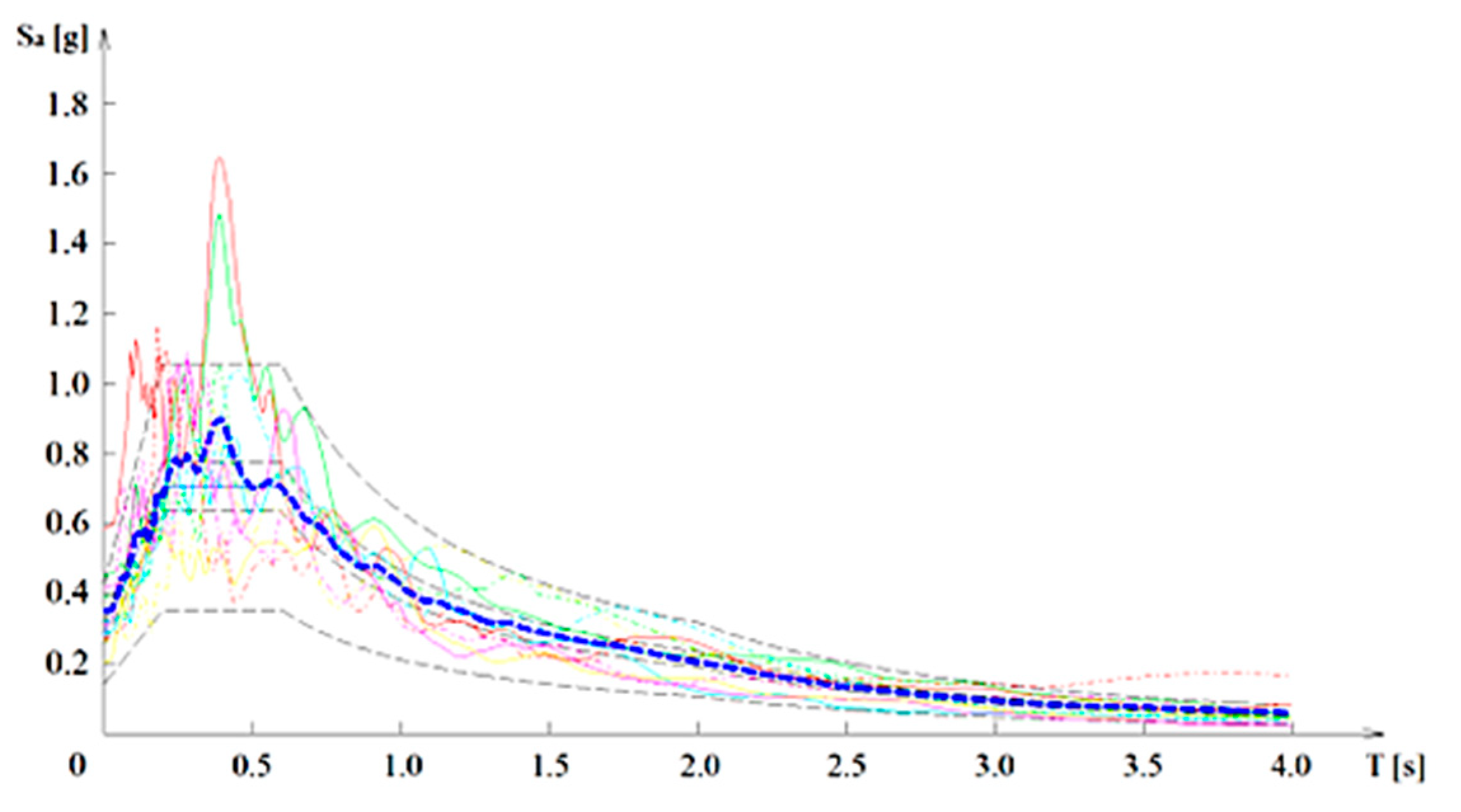
Nonlinear dynamic analyses (NDAs) were performed to accurately assess the post-seismic robustness of the designed structures. The accuracy of seismic input representation is crucial for assessing the structural performance of moment-resisting frames under extreme scenarios. Recent studies [25] have highlighted that realistic loading protocols, including those based on cumulative energy demand, can significantly influence the predicted ductility and failure mechanisms of frame components. In this study, natural ground motions scaled to Eurocode 8 spectra are adopted, ensuring compatibility with design conditions while capturing the essential features of seismic demand. These signals were selected according to Eurocode 8 [15], using the SelEQ application [26]; the data of the records are reported in Table 3, while the comparison of individual and average signal response spectra with the target ones provided by EC8 is shown in Figure 2: the scaled signals provide a very good fit with the target response spectra, namely, in the period range corresponding to the natural periods of vibration of the analysed structures.

3.2. Modelling Assumptions

The numerical models were created using the Seismostruct software (v2025) [27], following a component-based modelling strategy. While grounded in well-established formulations from the literature, each structural component—including joints, claddings, and panel zones—was specifically adjusted and calibrated against experimental data to accurately reproduce post-seismic behaviour and potential progressive collapse scenarios.
To verify the reliability of the adopted modelling techniques, key structural elements were validated through detailed comparison with experimental results reported in the literature, as presented in Figures 4–8.
Three-dimensional modelling was adopted for the analysed structures, since 2D representations, as highlighted by [28], tend to produce exaggerated and unrealistic deformations due to their limited ability to redistribute internal forces.
Structural members were modelled using force-based (FB) distributed inelasticity elements, which capture nonlinear behaviour by integrating the material response over the cross section and along the member length. The cross-sectional behaviour was represented via the fibre approach: uniaxial stress–strain laws were assigned to individual fibres. The hysteretic behaviour of steel was modelled with the Menegotto–Pinto model [29], while the yield strength was defined as the nominal steel yield stress from EN 1993-1-1 [22] multiplied by the γov factor from EN 1998-1 [15], to account for material variability.
Gravity loads not directly tributary to the analysed frames were applied to a leaning column with negligible stiffness, connected through pinned rigid links, to simulate second-order effects.
Full-scale experimental investigations and nonlinear analyses of steel–concrete joints by Xu et al. [30] confirmed the significant role of joint geometry in governing load transfer and deformation capacity under severe loading conditions.
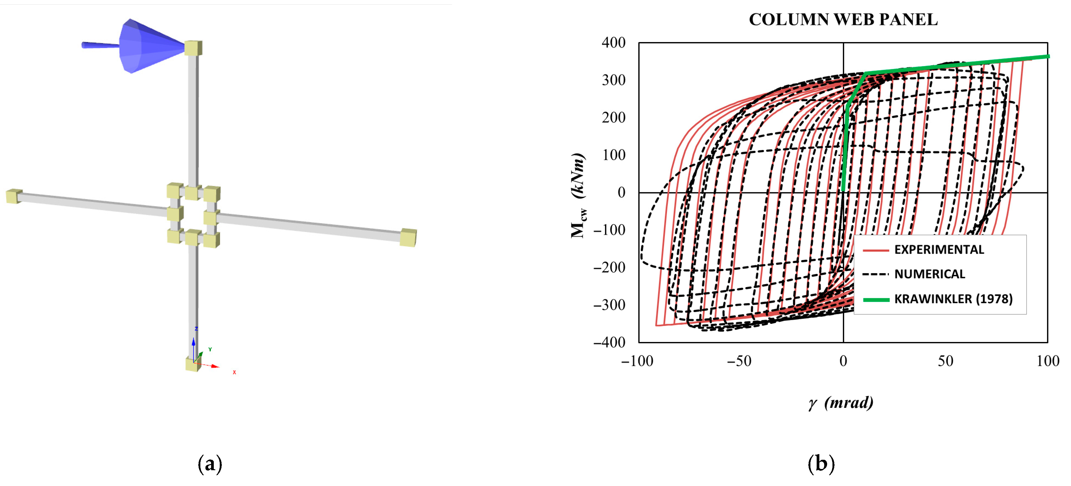
Seismic and wind actions induce large shear forces within the column web panel (CWP) of moment-resisting frame (MRF) beam-to-column connections, leading to considerable energy dissipation in these zones. Furthermore, the deformation of the CWP contributes substantially to joint rotational capacity [31] and affects the overall lateral drift and base shear resistance [32].
To represent the shear response of the panel zone in MRF beam-to-column joints, the geometry of the joint was modelled using a fictitious rigid frame reflecting the dimensions of the CWP. Each rigid element was pinned at both ends, and rotational springs located at the upper corners (see Figure 3) were introduced to simulate the shear-distortion behaviour of the panel zone, using a Ramberg–Osgood hysteresis formulation.
Although several mathematical models exist in the literature for the shear-distortion behaviour of panel zones [33,34,35], in this study, the springs were defined with a Ramberg–Osgood-type relationship. Yielding parameters, specifically the yielding moment and rotation, were derived analytically, whereas other parameters (the Ramberg–Osgood constant and the convergence limit for the Newton–Raphson procedure) were calibrated against experimental data provided by Dubina and Ciutina [31]. Yielding parameters were calculated according to the approach proposed by Gupta [34], using the following equations:
V y = F y 3 A e f f = F y 3 0.95 h c t p 0.55 F y h c t p ,
M y = V y ( h b t f . b )
γ y = F y 3 × G
where Fy is the material yield strength, Aeff is the effective shear area, hc is the depth of the column, and tp is the thickness of the web, including doubler plates. My is the moment corresponding to the plastic shear Vy; hb is the beam height and tf.b is the beam flange thickness; γy is the distortion corresponding to the yielding of the panel in shear; and G is the shear modulus of the column material.
Figure 3. (a) Trilinear shear-force-distortion law by [34]; (b) web panel refined model.
Buildings 15 02490 g003
The accuracy of the above-described modelling assumptions was calibrated and validated according to experimental tests by [31] (test specimen CP-R-C); a good match between the experimental and numerical results is confirmed in Figure 4.
Figure 4. Calibration [31]: (a) Seismostruct (v2025) model and (b) comparison between experimental and numerical Ramberg–Osgood model and monotonic [33] model prediction.
Buildings 15 02490 g004
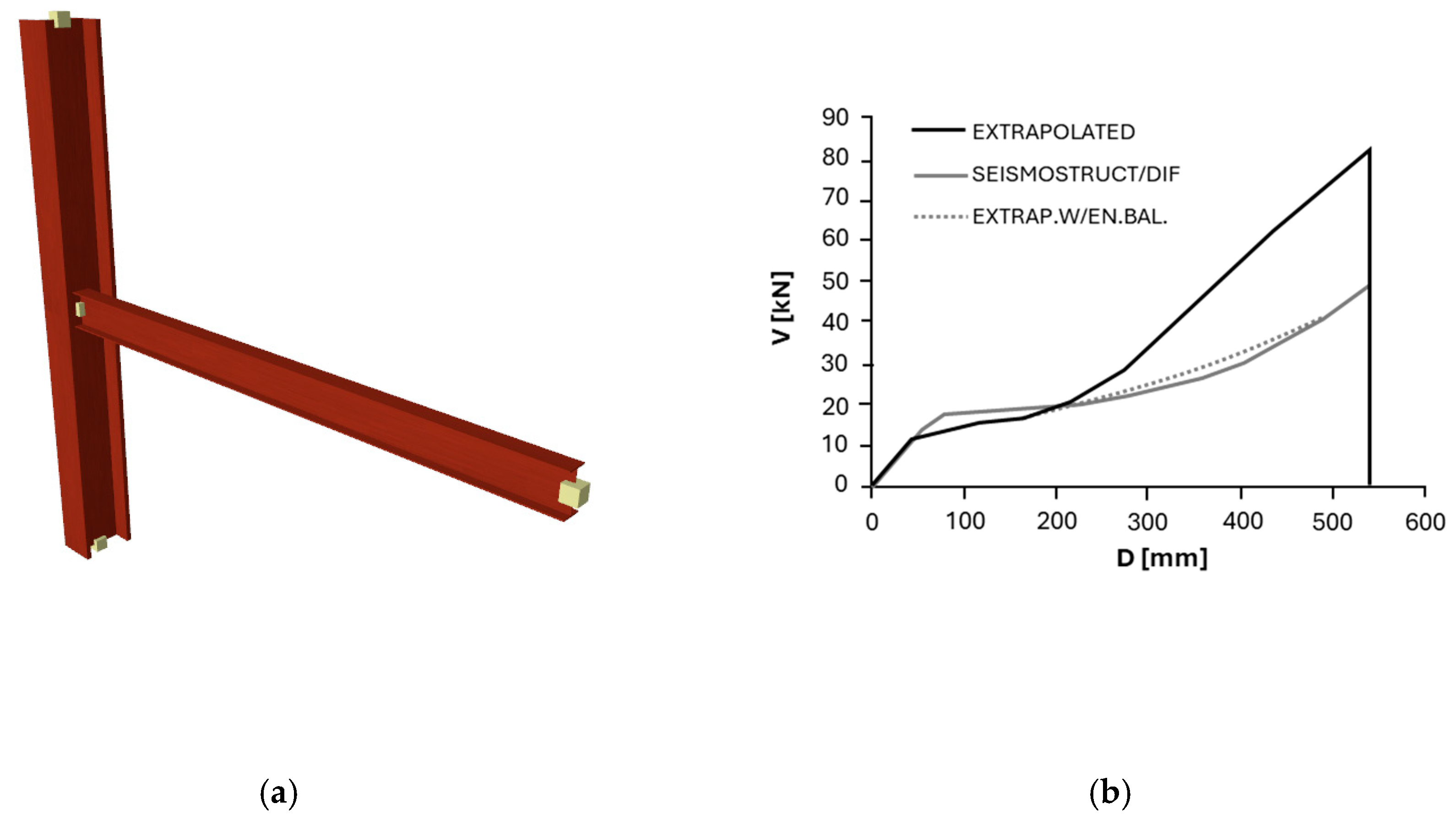
For beam-to-column FEP joints under column loss, no catenary final stage can be achieved, as shown by [36,37]; therefore, the joints behave as weak fuses, while the beam member remains largely elastic. The beams of the gravity frame were hence modelled using elastic frame elements, while the connections were modelled using nonlinear links. The characterisation of the Seismostruct (v2025) nonlinear link elements for gravity beam-to-column joints was performed separately for joints aligned with the weak and strong axes of the columns. For both configurations, the procedure was based on results from the parametric study on flush end-plate (FEP) joints presented by [36]. In cases not directly investigated by [36], the joint response curves were extrapolated using power regression expressions based on beam section mechanical properties. For both weak and strong axis connections, the joint moment–rotation curves were derived through a weighted average of the relevant existing curves for the same beam profile type (e.g., IPE or HE sections). Ultimate capacities in terms of the bending moment, axial force, and chord rotation were defined through regression models as functions of the beam plastic modulus and cross-sectional area. These normalised parameters—M/Mp, N/Np, and θchordp+A—were used to calibrate the target joint response up to failure.
Link properties along the bending and axial force directions were defined with an elastic–perfectly plastic law (zero hardening), while all other degrees of freedom were assigned high-stiffness linear elastic properties to simulate rigid behaviour. To account for dynamic effects, the force–displacement response curves were scaled by a dynamic increase factor (DIF) derived through energy balance, assuming a single-degree-of-freedom (SDOF) representation of the joint behaviour. A constant DIF value—calibrated to match the dynamic response of benchmark configurations—was applied to ensure consistency with the experimental and numerical references.
For instance, Figure 5 shows the comparison between the numerical response curves obtained by the Seismostruct (v2025) model with a nonlinear link and the response curve extrapolated for the weak axis of an IPE 240 joint based on results by [36]. As it can be argued, link modelling is capable of accurately simulating the static joint response, yielding a slightly smaller and, hence, conservative catenary axial force at collapse, when compared to the response curve.
Figure 5. Calibration of the extrapolated IPE 240 joint: (a) Seismostruct (v2025) model with nonlinear link; (b) vertical force–displacement static and dynamic energy balance equivalent comparison; (c) static moment–rotation comparison; and (d) axial force–rotation static ì.
Buildings 15 02490 g005aBuildings 15 02490 g005b
A spring with six degrees of freedom (DOFs) was defined to simulate the web cleat joint link behaviour. Its properties were evaluated by using the component-based mechanical model based on Liu, Tan, & Fung [38] and Yang & Tan [39]. The joint response for the DOF in bending about the beam’s strong axis was defined using the bilinear kinematic formulation with kinematic hardening, to model elastic–plastic behaviour. The yield moment was computed when the bolted angle component reached its capacity [39], and zero hardening was assumed to limit the bending resistance contribution; at high rotation demands, the resistance is provided by the axial force contribution that is mobilised by catenary action. For the definition of the horizontal translation DOF, a trilinear symmetric with isotropic hardening formulation was adopted, which can simulate the hardening effect under large displacements up to failure. The horizontal and vertical shear DOFs were modelled using the bilinear kinematic formulation according to the previously described shear stiffness and strength capacity of the bolt components.
For the adopted tensile and vertical shear response curve formulations, joint resistance continues to increase, even after angle failure, since the formulation provided in the Seismostruct (v2025) library does not allow for the modelling of a sudden drop in resistance or negative stiffness values. In this sense, in order to clearly identify the bolted angle failure, the vertical shear DOF resistance was limited to match the vertical force, which leads to bolted angle failure. This allows for a zero-hardening condition (i.e., approximately horizontal force–displacement segment) to be obtained at bolted angle failure, which in turn enables the identification and subsequent truncation of the structural response curve, since the response further to partial structural collapse falls outside the scope of the present study. The joint DOFs pertaining to beam torsion and bending about the weak axis were assumed to be rigid.
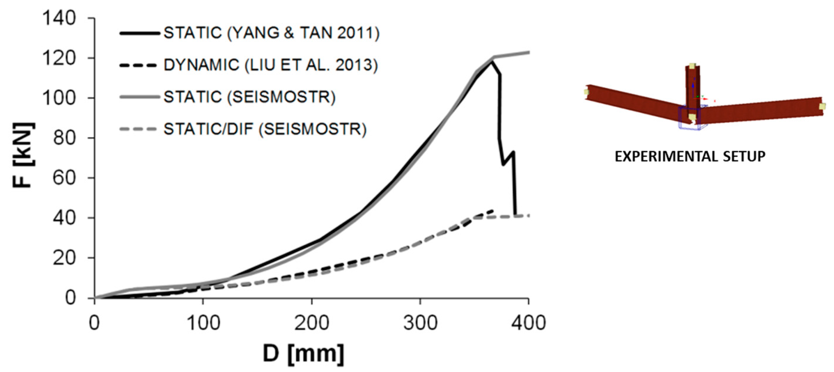
The numerical model was validated against experimental static results by [40] and numerical dynamic results by [38].
As shown in Figure 6, the adopted link definition can satisfactorily simulate the web cleat static response under column loss at large displacements. The differences observed at low displacement values are due to the fact that the response input for each DOF in the Seismostruct (v2025) is decoupled and that for low displacement values, the bilinear response in bending is dominant. The response in pure bending (i.e., without axial restriction) for low displacements is intended to model the response of gravity frame joints under seismic action. Dynamic effects were considered by dividing the static curve by a constant force-based DIF = 2.8. In this case, despite the fact that the DIF varies with the applied displacement, adopting a constant DIF is shown to provide good agreement with the dynamic response curve by [38].
Figure 6. Seismostruct (v2025) model to simulate [40] comparison between experimental static [39], numerical dynamic [38], and Seismostruct (v2025) static and dynamic equivalent nonlinear link vertical force–displacement response.
Buildings 15 02490 g006
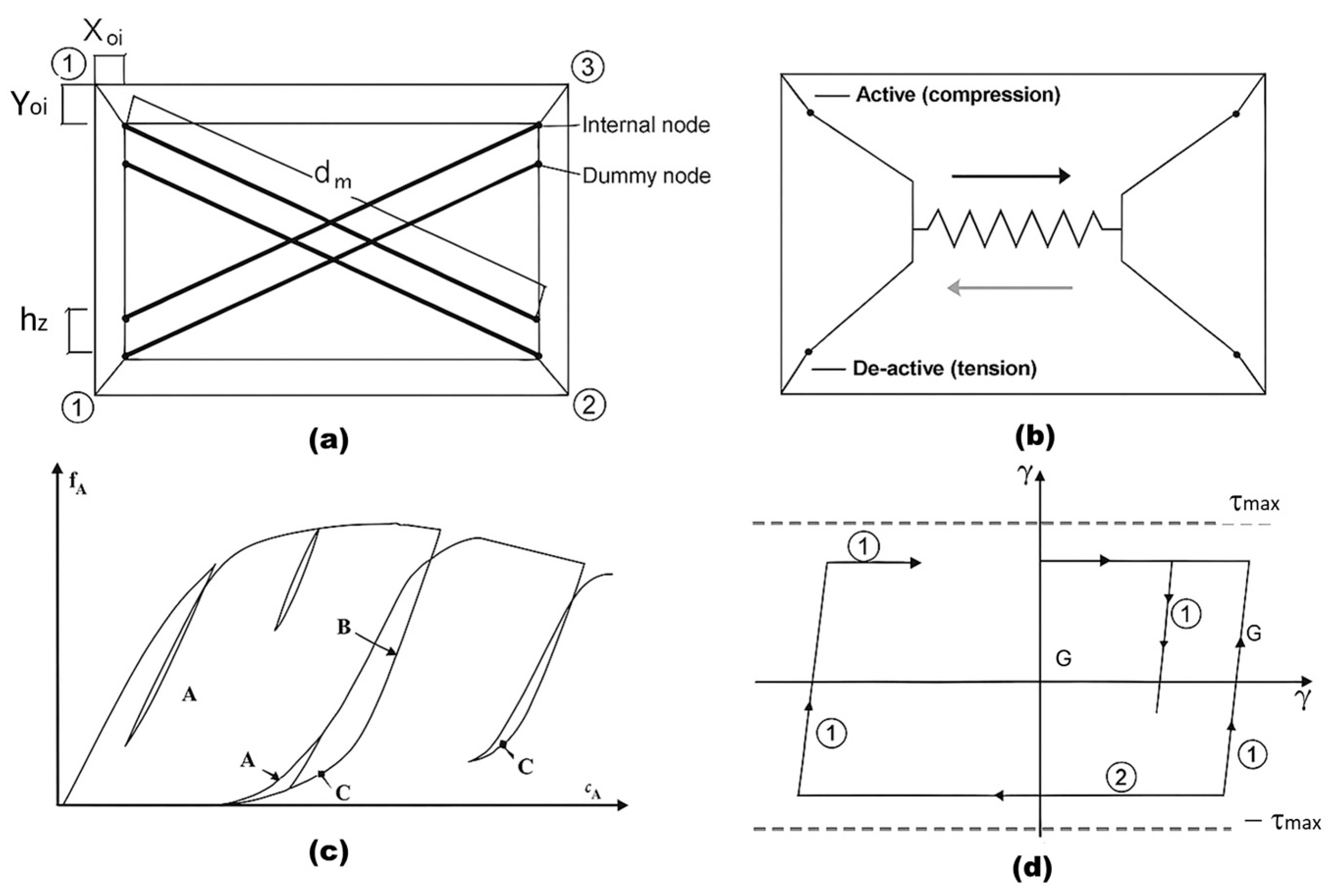
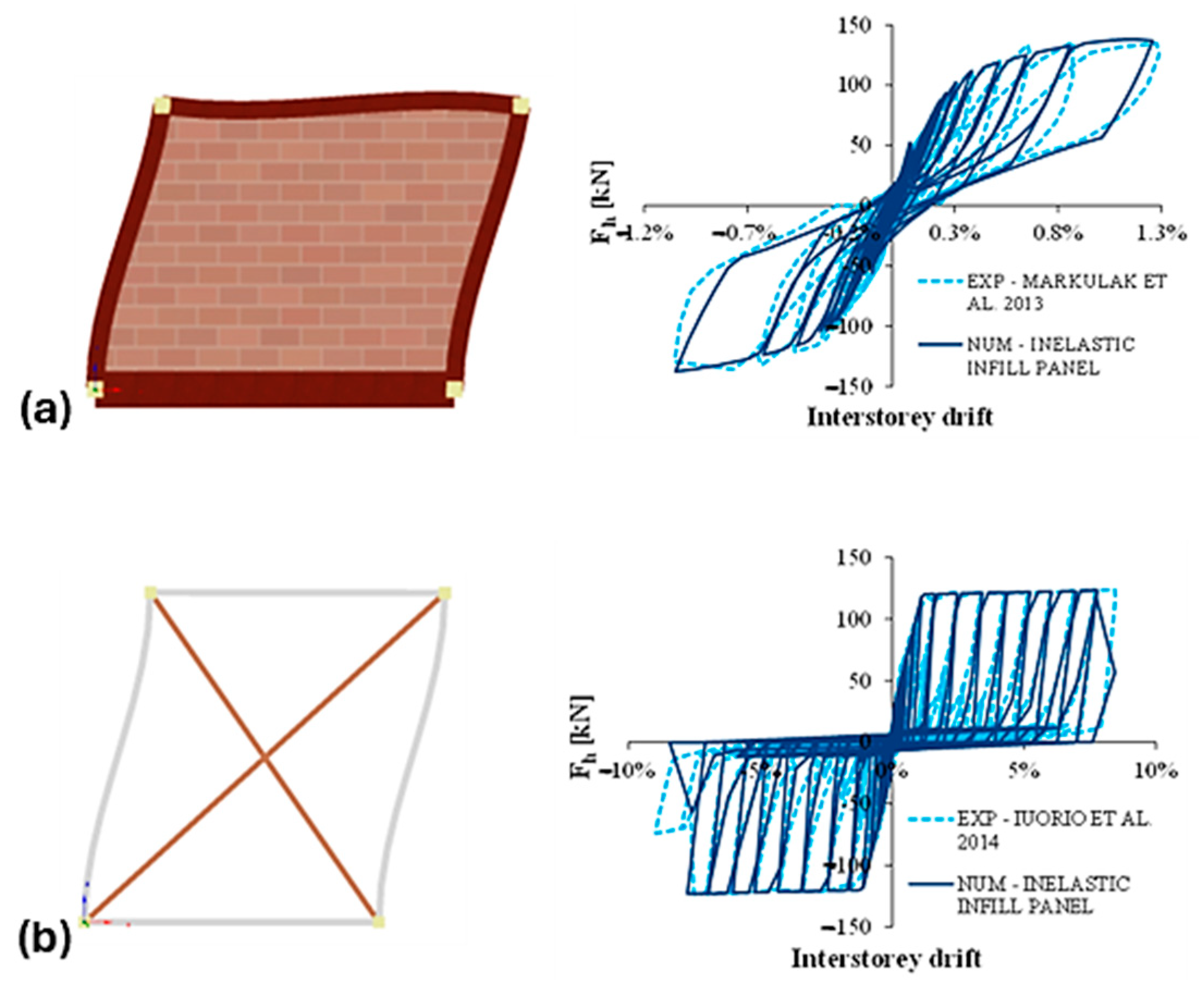
The contribution of claddings is simulated by using the equivalent diagonal strut model [41,42]; according to this model, the infill panel is simulated by a diagonal strut under compression load, located between two opposite nodes of the frame. In particular, the inelastic infill panel element-type formulation provided in Seismostruct (v2025) was adopted. This formulation (see Figure 7) considers each panel to be represented by six strut members, where each diagonal direction features two parallel struts that transfer axial loads between opposing panel corners, plus a third diagonal element that carries the shear load and that is activated in compression only.
Figure 7. Seismostruct inelastic infill panel model: (a) compressions struts; (b) shear strut; (c) masonry strut hysteretic model; and (d) masonry shear strut hysteretic model.
Buildings 15 02490 g007
The inelastic infill panel model was specifically calibrated to simulate the dynamic behaviour of masonry and CFS claddings, and the relevant accuracy was validated against experimental results. For masonry claddings, experimental tests described in [43] were considered, while for façade claddings consisting of strap-braced cold-formed steel (CFS), tests conducted by [44] were used. The comparison between the experimental and the numerical response curves is shown in Figure 8a,b for masonry and CFS claddings, respectively; in both cases, a good match between the experimental and numerical hysteretic curves can be argued (see Figure 8).
Global mechanisms (e.g., internal arching, catenary action, and frame instability) were reproduced in consistency with experimental observations reported in prior large-scale tests, particularly those referenced in [31,38,40,43,44].
Figure 8. Validation of cladding numerical model: deformed shape and force–interstorey drift response curve of (a) masonry claddings (against [43]) and (b) CFS claddings (against [44]).
Buildings 15 02490 g008

3.3. Monitored Parameters

To assess the structural performance under column loss scenarios, the contribution of the different collapse-resisting mechanisms need to be taken into account [45], namely, the (i) frame catenary action; (ii) shear deformation of deep transfer beams; (iii) membrane action in slabs with central column removal; (iv) Vierendeel action; (v) compressive arching action between composite slab and steel beams; and (vi) compressive strut action in façade claddings.
Frame catenary action, shear deformation, and Vierendeel action were explicitly modelled in Seismostruct (v2025); membrane action in slabs was not modelled, as the study focused on bare steel structures without composite slab interaction, while compressive arching action was considered to be zero because the beams were disconnected from the slabs at their ends; cladding strut action was accounted for by the explicit modelling of infill panels.
In addition, the following quantitative performance indicators were monitored:
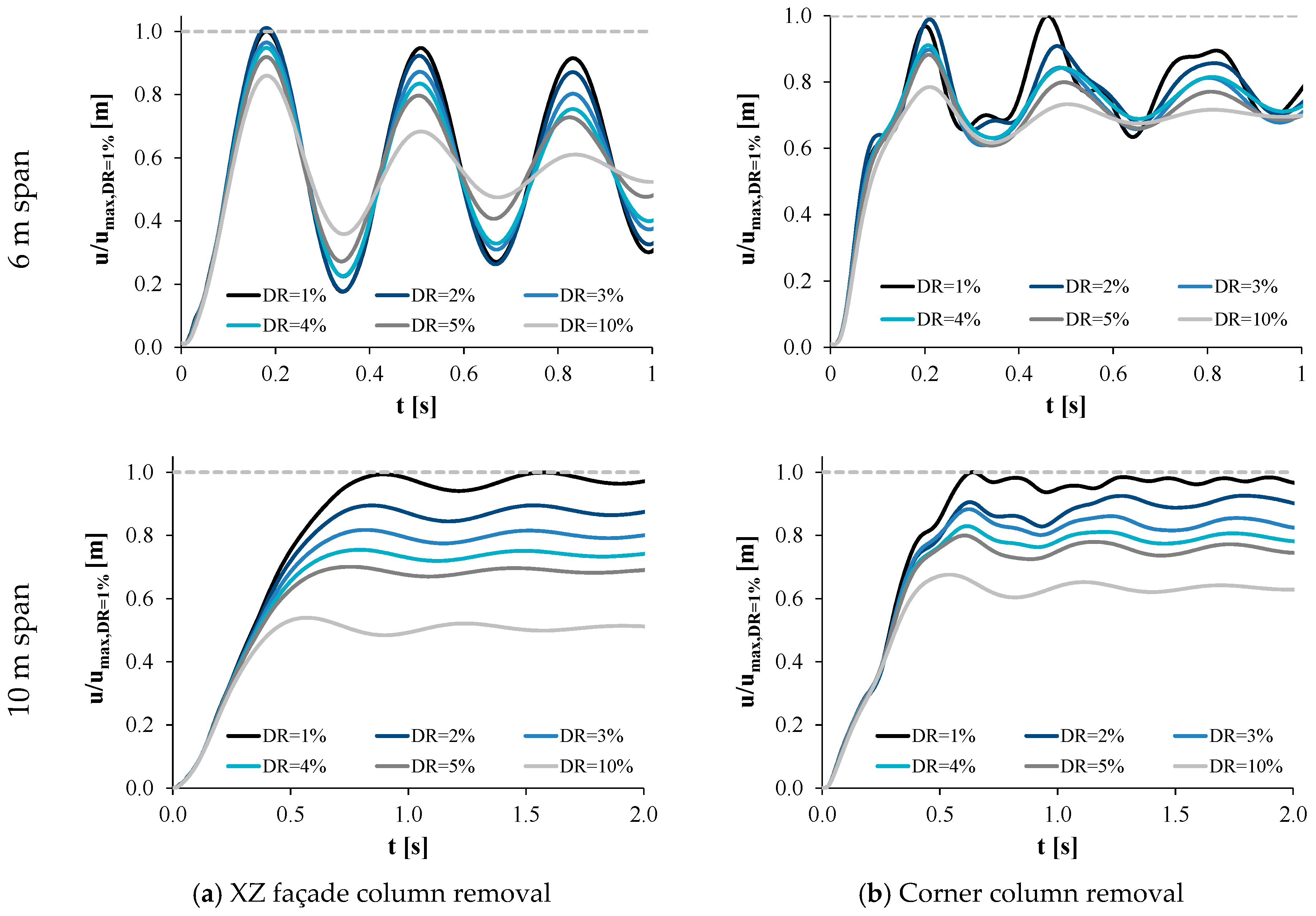
  • The damping ratio (DR): This parameter was found to significantly affect the dynamic response under column loss [46]; a sensitivity analysis was performed to investigate the influence of the damping ratio, by varying it between 1% and 10%, and to determine the value to be assumed during the NDA.
  • Vertical displacement under column loss was monitored.
  • To quantify the capacity of the system to mobilise plasticity for arresting the progressive collapse, the degree of plasticity (DOP) in the directly affected zones (DAZs) (DOPDAZ) was computed as follows:
    D O P D A Z = u d y n , e q u i l , d a m a g e d u d y n , m a x , d a m a g e d
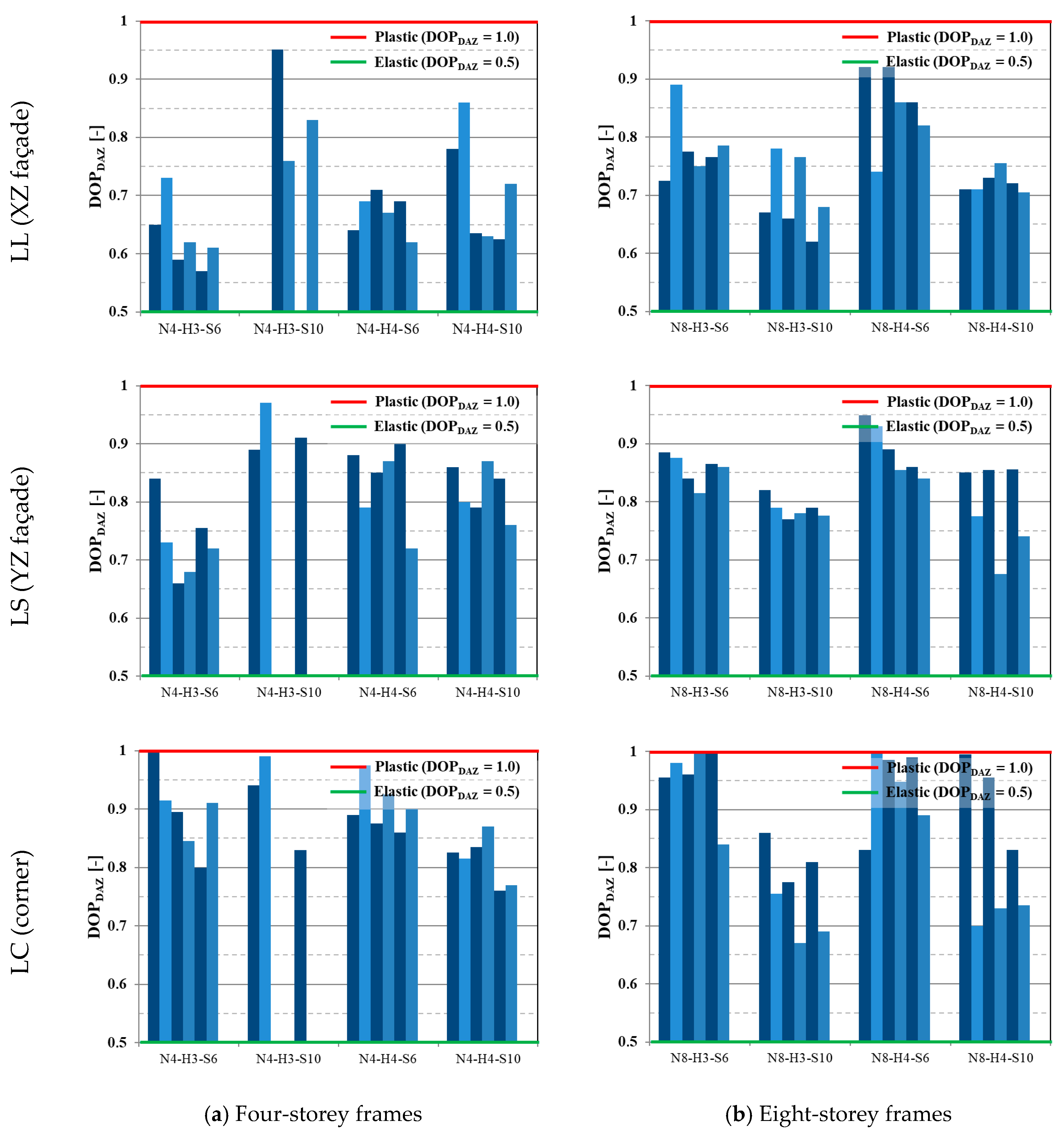
    The DOPDAZ can vary between 0.5 for a fully elastic DAZ response and 1 for perfectly plastic behaviour. This ratio enables the quantification of the capacity of different structural typologies to mobilise plasticity for arresting the progressive collapse.
  • Rotational demand: The total chord rotational demand ϕ was computed as the arctangent of the ratio between the maximum dynamic vertical displacement udyn,max,damaged and the span L.
  • To quantify the system’s reserve displacement capacity, the Residual Ductility Ratio (RDR) was computed as follows:
    R D R = u u , d a m a g e d u d y n , d a m a g e d
    where (uu,damaged) is the system’s displacement immediately prior to global collapse and (udyn,damaged) is the maximum dynamic displacement evaluated through NDA.
  • To assess the structural safety in post-seismic scenarios involving column loss, the system’s residual ductility was evaluated through the RDDequil ratio, defined as the ratio between the ultimate displacement capacity uu,damaged and the stabilised dynamic equilibrium displacement after damage, udyn,equil,damaged (see Equation (6)). This parameter provides a more realistic measure of the reserve capacity at the time of potential rescue interventions, compared to ratios based on the peak dynamic response.
    R D D e q u i l = u u , d a m a g e d u d y n , e q u i l , d a m a g e d = u u , d a m a g e d D O P D A Z · u d y n , m a x , d a m a g e d
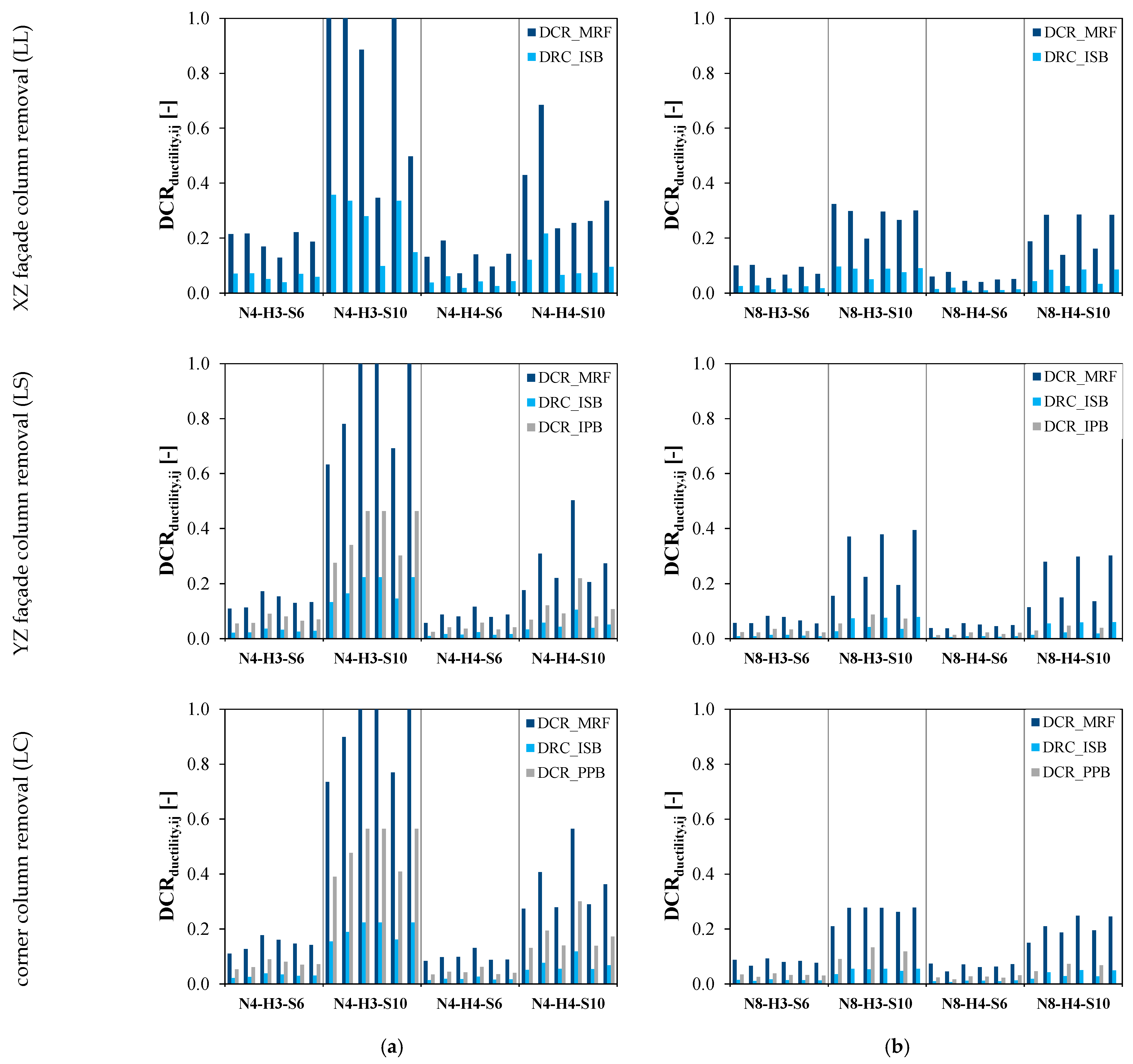
  • Additionally, ductility demand-to-capacity ratios (DCRductility) were computed for moment-resisting frame (MRF) members and secondary gravity frame components to identify the structural elements most susceptible to ductility demands exceeding their capacity, thus clarifying retrofit priorities and contributing to the development of design recommendations aimed at enhancing global structural robustness. The ductility DCR ratio for member i in structure j was computed according to the following expression:
    D C R d u c t i l i t y , i j = u d y n , d a m a g e d , j u u , d a m a g e d , i
    where (udyn,damaged,j) is the maximum dynamic displacement (or rotation) subsequent to column removal in structure j (depends on the characteristics of structure j and all members i), i.e., the ductility demand, whereas (uu,damaged,i) is the ultimate displacement (or rotation) capacity of member i when subjected to column loss action (is independent of the characteristics of structure j), i.e., the member ductility capacity.

4. Results

4.1. Baseline Robustness

4.1.1. Sensitivity to Damping Ratio

A sensitivity analysis was performed to investigate the influence of the DR on the dynamic response under column loss; two column loss scenarios were considered, namely, XZ (longitudinal) façade and corner cases.
For the XZ façade column scenario (Figure 8a), the response is predominantly elastic, and the damping poorly affects the maximum dynamic displacement, with u/umax,DR=1% ratio values equal to 1.00, 0.96, 0.94, 0.91, and 0.86 for damping ratios of 2%, 3%, 4%, 5%, and 10%, respectively. Conversely, for the corner column removal case shown in Figure 9b, the response is significantly more complex, and the effect of the damping is more pronounced, with u/umax,DR=1% ratio values equal to 0.98, 0.90, 0.91, 0.88, and 0.78 for damping ratios of 2%, 3%, 4%, 5%, and 10%, respectively. As seen in Figure 8, the effect of damping on the maximum dynamic displacement following column loss is considerably magnified when the span increases. For the façade removal, the u/umax,DR=1% ratio values are equal to 0.90, 0.82, 0.75, 0.70, and 0.54 for damping ratios of 2%, 3%, 4%, 5%, and 10%, respectively. On the other hand, for the corner removal, u/umax,DR=1% values of 0.93, 0.88, 0.83, 0.80, and 0.68 are reported for damping ratios of 2%, 3%, 4%, 5%, and 10%, respectively.
These results confirm the importance of the damping ratio as a key parameter influencing the progressive collapse arrest, mostly in long-span frames; in order to avoid excessive and unrealistic displacement reduction, the value of DR = 2% was adopted in the dynamic analyses, as it is typically considered for building steel frames.

4.1.2. Displacement Time History Under Column Loss

The dynamic response of low- (N4-H3-CN-T5×3-DE) and medium-rise (N8-H3-CN-T5×4-DG) frames is presented in Figure 10 in terms of the vertical displacement time history for (a) 6 m and (b) 10 m span cases. For the low-rise frame, the amplitude of the maximum displacement is approximately 10 times greater than that for the long-span frame; for the latter case, a high level of plasticity is required in the DAZ, leading to DOPDAZ values (see Equation (4)) approximately equal to 1 (the maximum dynamic displacement udyn,max,damaged and the displacement at equilibrium udyn,equil,damaged are practically equal in value). Conversely, for the short-span frame, the response to column loss for the different removal scenarios shows that for scenarios S1 and S2 (i.e., façade column removals), the system preserves a degree of elasticity, which leads the displacement at equilibrium to be smaller in value than the maximum dynamic displacement (DOPDAZ values are equal to 0.73 for both façade removal scenarios). For the eight-storey frames, the maximum dynamic displacements are generally smaller when compared to the corresponding low-rise structures due to the larger number of elements the load is redistributed to, allowing some DAZs to remain in the elastic range and thus resulting in larger RDD (see Equation (6)) and robustness.

4.1.3. Degree of Plasticity of Directly Affected Zones

The degree of plasticity of the directly affected zones (DOPDAZ ratios, see Equation (4)) for the considered column removal scenarios is presented in Figure 11 for low- and medium-rise frames (zero corresponds to collapsed structures). The numerical results show that significant plasticity is required to arrest a progressive collapse, with DOPDAZ ratios higher than 0.5 in all cases. Figure 10 shows that corner column loss cases require the development of a higher level of plasticity in the DAZs in comparison to façade losses. In turn, by comparing the two façade removal cases LL (XZ façade) and LS (YZ façade), it is possible to verify that higher DOPDAZ ratios are obtained for the LS case. The differences in terms of the degree of plasticity are mainly attributed to the different secondary frame systems that are activated upon column removal, as shown in Figure 12. For the LL case, the mobilised secondary frame joints are nominally pinned and, hence, more flexible, which explains the lower DOPDAZ ratios. Conversely, for the LS case, the main mobilised gravity frame joints are semi-rigid partial-strength joints, which are comparatively more rigid and therefore tend to develop plasticity for lower rotational demands, leading to higher DOPDAZ ratios. For the interstorey height, no correlation was found with the degree of plasticity. The span variable was found to influence the DOPDAZ ratios, namely, for four-storey frames, which have inherently lower structural robustness and which for 10 m span frames display an average DOPDAZ ratio increase of 11% when compared to the corresponding 6 m span frames. This is due to long-span systems being required to further develop catenary action and connection plasticity in order to arrest the collapse. Conversely, for eight-storey structures, which display much higher robustness due to the higher number of elements in the DAZ that are mobilised under column loss, 10 m span frames display an average decrease in the DOPDAZ ratios of 13% when compared to 6 m span frames. This difference is explained by the lateral sway limitation requirements for the eight-storey 10 m span frames, which require large profiles that tend to develop less plasticity under column loss.

4.1.4. Reserve Displacement Ductility (RDDequil)

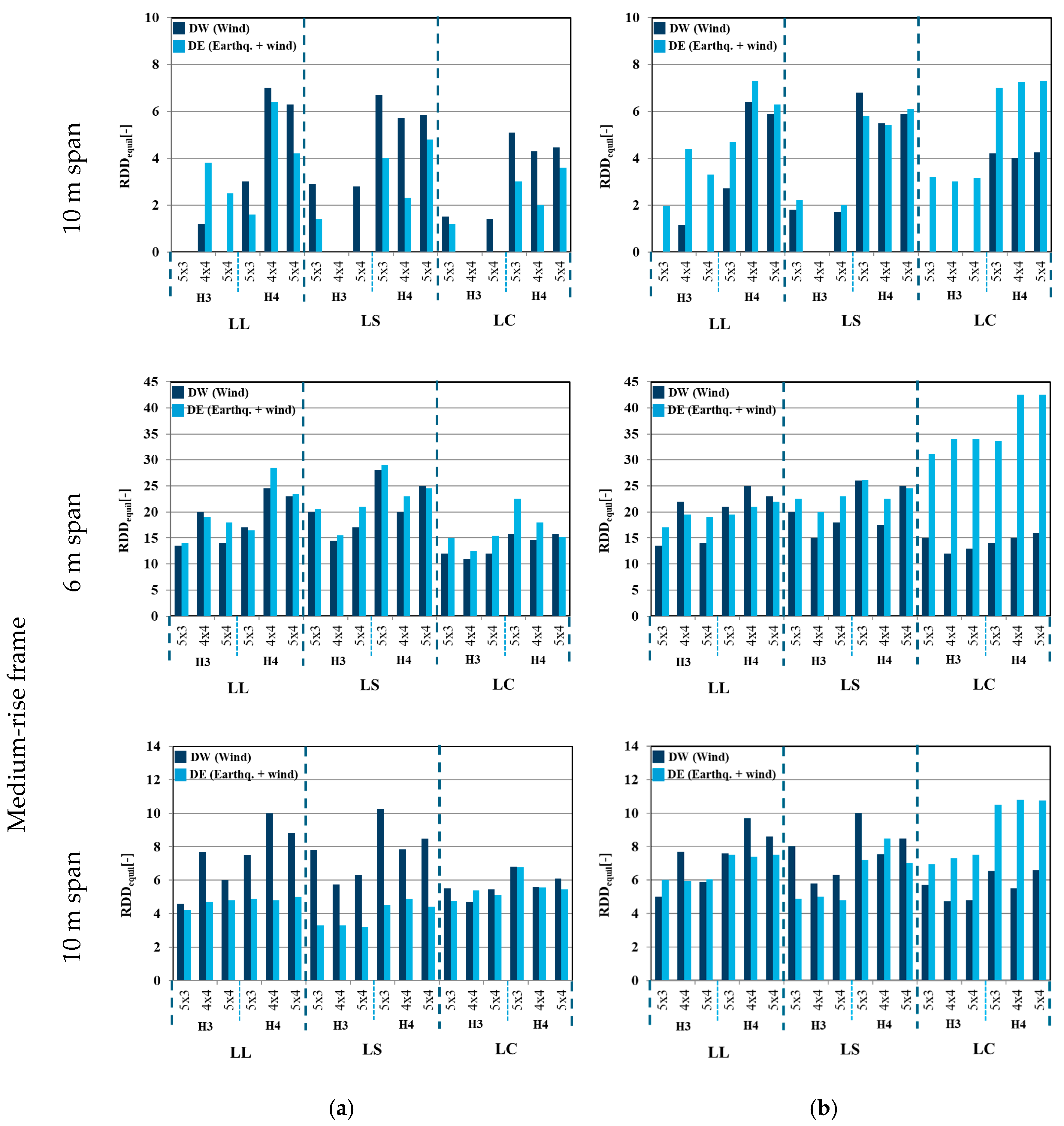
Reserve Displacement Ductility is reported in Figure 13, where the effect of claddings is also highlighted (results are separately presented for the bare steel frame and for the frame with façade claddings (masonry for DW cases, and CF for DE ones); zero values of RDDequil are indicative of collapsed frames).
The results show that bare steel frames with a medium span (S6) display high reserve ductility values, which are indicative of high robustness and internal redistribution capacity, with corner removal (LC) cases showing smaller reserve when compared to façade removals (LL and LS). In terms of the RDDequil values, a minimum RDDequil value of 6.3 and average values of 10.7, 12.6, and 9.8 are reported for the LL, LS, and LC column removal scenarios, respectively, for low-rise frames and minimum values of 13.8, 14.6, and 11.2 and average values of 19.7, 21.5, and 15.0 for the LL, LS, and LC column removal scenarios, respectively, are reported for eight-storey cases. These values indicate that medium-span frames exhibit high structural robustness and satisfactory capacity of arresting progressive collapse.
Concerning the effect of claddings, CF claddings (DE cases) significantly increase the reserve of ductility (with average increases in the RDDequil of 4% and 129% for façade and corner losses reported for four-storey cases and average increases in the RDDequil of 47% and 64% reported for façade and corner losses for eight-storey cases), while negligible improvement can be recognised for masonry claddings in DW cases.

4.1.5. Demand-to-Capacity Ratios (DCRductility,ij)

The evaluation of the reserve displacement of different members/connections presented in this section was performed for the maximum dynamic displacement (u = udyn,max,damaged). The chord rotations corresponding to udyn,max,damaged were computed for the different members/connections and compared to their predicted ultimate rotation capacities. For the moment-resisting frame welded beams-to-column joints, which are full-strength rigid connections, the ultimate rotation capacity was evaluated according to the nonlinear modelling criteria for fully restrained moment connections provided in the UFC 2013 [12]. The ultimate displacement capacity of the web cleat beam-to-beam joints was computed directly from the moment–chord rotation experimental response curve in Figure 6, while the ultimate displacement of the secondary frame beam-to-column joints was computed from the FEP joint chord rotation capacities which were determined considering the static response and subsequently corrected by a dynamic factor (DIF) determined according to [32].
Considering that the different column loss scenarios mobilise different members of the DAZ, the demand-to-capacity ratios DCRductility,ij (see Equation (7)) were computed for each removal scenario.
For the XZ façade removal (LL case), MRF beams and Internal Secondary Beam (ISB) web cleat connections are activated (the ISB member itself remains elastic), whereas for the YZ façade removal (LS case), MRF beams, Internal Secondary Beams (beam-to-beam web cleat joints), and Internal Primary Beams (beam-to-column flush end-plate joints) are mobilised. For the corner column loss (LC case), MRF beams, Internal Secondary Beams (beam-to-beam web cleat joints), and Perimeter Primary Beams (beam-to-column flush end-plate joints) are activated.
The results for the LL, LS, and LC cases for four-storey and eight-storey frames are presented in Figure 14, where DCR ratios of 1.0 are indicative of member/connection failure and where MRF, ISB, IPB, and PPB stand for moment-resisting frame, Internal Secondary Beam, Internal Primary Beam, and Peripheral Primary Beam, respectively.
The summarised results show that for all analysed structures, the MRF beam joints display the highest DCR values, while gravity frame joints tend to present very low values, owing to their high flexibility, which can accommodate very large rotations without failure. Indeed, for N4-S6 frames, the MRF beams display a maximum DCRductility of 0.22, while “gravity” frame joints display ratio values smaller than 0.09, i.e., approximately half. This is also seen for the cases of N8-S6 and N8-S10 typologies, with displayed maximum MRF ratio values of 0.10 and 0.39, compared to the maximum ratio values of the secondary frame joints of 0.04 and 0.13. It should be noted that it is for the LC removal scenario that secondary joints display the highest DCRductility values. Most of the cases (except N4-S10 frames) did not collapse under column loss, and the small ratio values indicate that further reinforcement is not required since there is a large margin of safety between the maximum dynamic displacement and the ultimate displacement causing structural collapse.

4.2. Post-Seismic Robustness

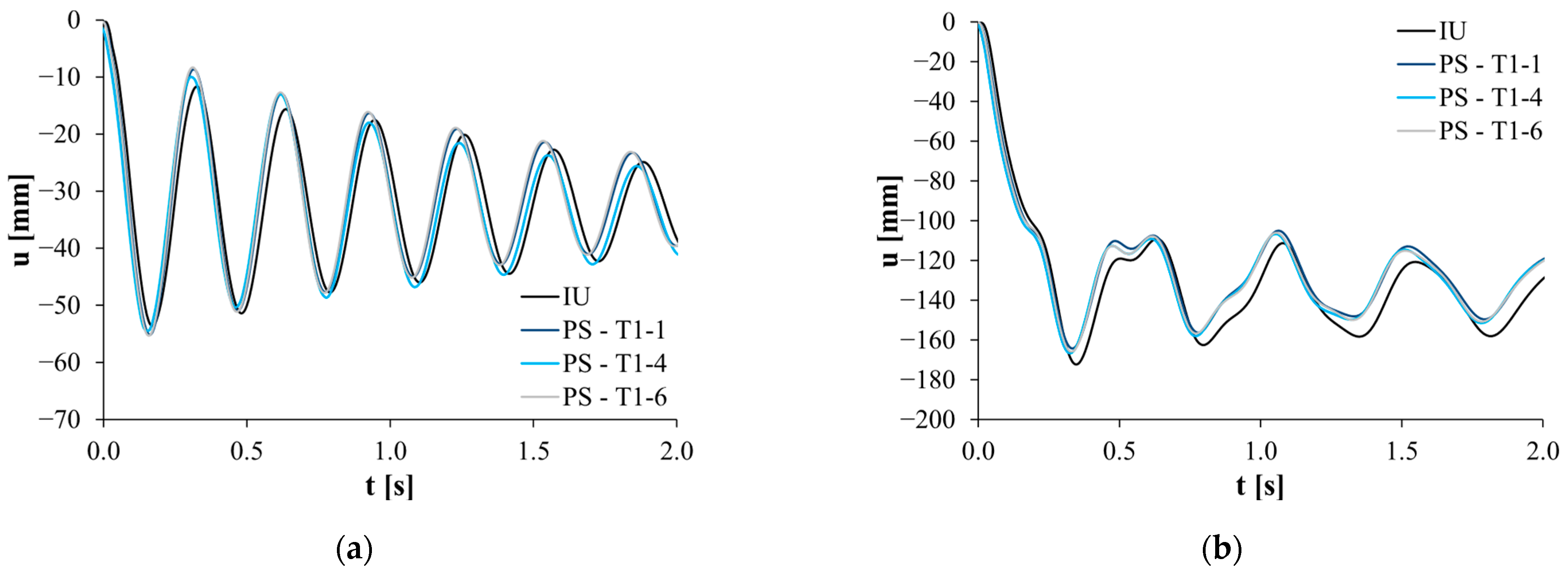
The amount of damage to the analysed frames induced by the seismic action was also evaluated by comparing the vertical displacement time-history (TH) responses between initially undamaged (IU) and post-seismic (PS) column loss cases. This comparison was performed for all four-storey frames (N4 cases) for the façade (LL) and corner column loss (LC) cases.
The obtained results generally indicate that the seismic action does not introduce significant variations in the maximum dynamic vertical displacements under the subsequent column loss action, since small damage levels are introduced by the seismic action. Two examples of this are presented in Figure 15, where the frame in Figure 15a is characterised by a predominantly elastic response to column loss (DOPDAZ ≈ 0.5), while the frame in Figure 15b is characterised by a predominantly plastic response to column loss (DOPDAZ ≈ 1.0).
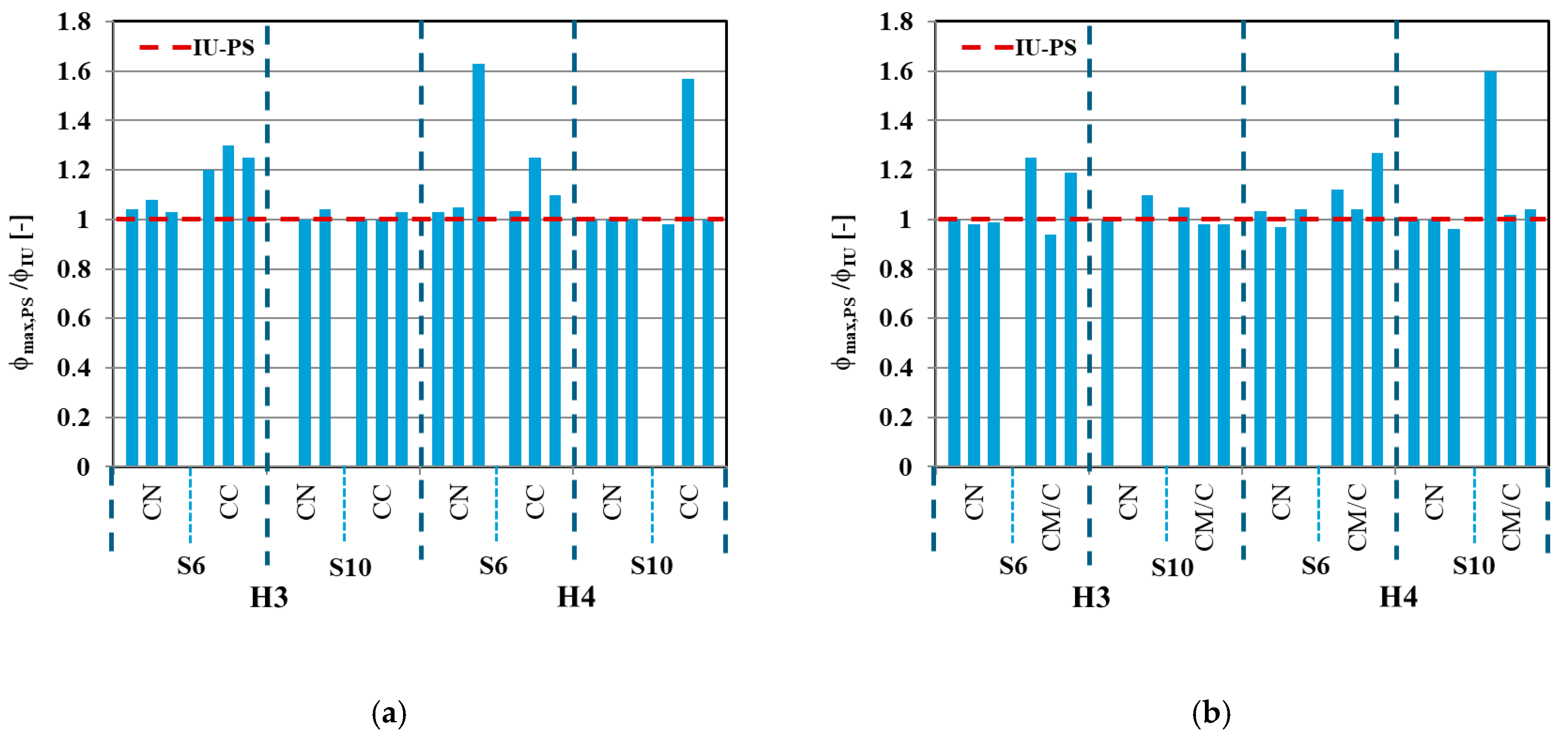
Figure 16 compares the response of the designed frames in terms of the rotation demand between the IU and PS scenarios: the chord rotation demand PS/IU ratios are very low, with ratio values being close to 1 for nearly all cases. Furthermore, all IU structures that arrested the progressive collapse also arrested the collapse in the PS scenarios, while structures that collapsed in the IU case (N4-H3-S10-CN-T5×3-DE-LL and N4-H3-S10-CN-T4×4-DE-LC) also collapsed in all PS scenarios, as expected.
Given the low damage levels or absence of damage introduced by the seismic action, the numerical results point to the fact that for the analysed frames, the post-seismic robustness is virtually the same as the robustness for the initially undamaged structure.

5. Concluding Remarks

The current paper was devoted to investigating the robustness of steel MRFs under column loss, considering both undamaged and post-seismic damage conditions. With this aim, a comprehensive set of nonlinear dynamic analyses (NDAs) was performed by using a refined modelling approach: full 3D finite element models were developed accounting for the contribution of the secondary frame and beam-to-column joints. The non-structural façade claddings were also modelled using nonlinear infill panel formulations calibrated with experimental results.
The interpretation of the results inferred the following remarks:
  • The initial sensitivity tests show maximum dynamic displacements to be sensitive to the damping ratio.
  • The analysis revealed that long-span, low-rise frames (e.g., four-storey frames with 10 m spans) proved to be particularly vulnerable to progressive collapse, exhibiting displacement demands roughly ten times higher than those of shorter-span frames. Conversely, higher-rise frames demonstrated enhanced internal redistribution capabilities due to increased Vierendeel action, yielding approximately 3–4 times higher (around 21.5 versus roughly 6.3) Reserve Displacement Ductility (RDD) values.
  • The reserve ductility ratio (RDD) was used to assess the safety margin after stabilisation. While medium-span frames showed robust behaviour (RDD ≈ 6.3), several long-span configurations had RDD values close to 1.0, indicating imminent collapse.
  • The role of non-structural claddings was also analysed. Cold-formed steel (CFS) claddings contributed effectively to robustness by reducing joint rotation demands and increasing energy dissipation. In contrast, masonry claddings were less effective, often failing to mobilise tensile resistance due to early fracture or detachment. The cladding contribution was particularly relevant in corner column loss scenarios.
  • Prior seismic damage introduced in the simulations had only a limited effect, increasing the rotational demands by roughly 5–10% compared with the undamaged state. Displacement histories and maximum rotations remained largely unchanged, suggesting that moderate earthquake damage may not significantly compromise the structure’s resistance to progressive collapse.
  • These results imply that for the analysed structural type, the design for progressive collapse in post-seismic scenarios can be made analogously to the initially undamaged structure scenario.
  • Further experimental studies are needed to characterise the overall robustness of steel moment frames, including the influence of non-structural elements.
In addition, the findings of this work point to the following recommendations for seismic retrofit and robustness-oriented design:
  • The importance of maintaining joint integrity and catenary capacity in perimeter beams;
  • The vulnerability of frames with long spans and unbraced layouts to the loss of vertical support;
  • The limited contribution of non-structural claddings to post-seismic robustness unless properly anchored.

Author Contributions

Conceptualisation, S.C. and D.C.; methodology, S.C.; software, D.C.; validation, S.C. and M.D.; formal analysis, S.C.; investigation, S.C.; resources, D.C.; data curation, S.C.; writing—original draft preparation, S.C.; writing—review and editing, M.D.; visualisation, S.C.; supervision, M.D.; project administration, S.C. and M.D.; funding acquisition, D.C. All authors have read and agreed to the published version of the manuscript.

Funding

This research received no external funding.

Data Availability Statement

The original contributions presented in the study are included in the article, further inquiries can be directed to the corresponding author.

Conflicts of Interest

Author David Cassiano was employed by the company Subsea7. The remaining authors declare that the research was conducted in the absence of any commercial or financial relationships that could be construed as a potential conflict of interest.

References

  1. Cassiano, D.; D’Aniello, M.; Rebelo, C.; Landolfo, R.; da Silva, L.S. Influence of seismic design rules on the robustness of steel moment resisting frames. Steel Compos. Struct. 2015, 21, 479–500. [Google Scholar] [CrossRef]
  2. Marchand, K.; McKay, A.; Stevens, D.J. Development and application of linear and nonlinear static approaches in UFC 4-023-03. In Proceedings of the Structures Congress 2009: Don’t Mess with Structural Engineers: Expanding Our Role, Austin, TX, USA, 30 April 2009. [Google Scholar] [CrossRef]
  3. Sadek, F.; Main, J.A.; Lew, H.S.; Bao, Y. Testing and Analysis of Steel and Concrete Beam-Column Assemblies under a Column Removal Scenario. J. Struct. Eng. 2011, 137, 881–892. [Google Scholar] [CrossRef]
  4. Krawinkler, H. System performance of steel moment resisting frame structures. In Proceedings of the 12th World Conference on Earthquake Engineering, Auckland: New Zealand Society for Earthquake Engineering, Salt Lake City, UT, USA, 27 June–1 July 2022. [Google Scholar] [CrossRef]
  5. Comeliau, L.; Demonceau, J.F.; Jaspart, J.P. Robustness of steel and composite buildings under impact loading. In Proceedings of the SDSS’Rio 2010 Stability and Ductility of Steel Structures, Rio de Janeiro, Brazil, 8–10 September 2010. [Google Scholar]
  6. Guo, L.; Zhang, S.; Shen, S. Numerical investigation on progressive collapse resistance of steel moment frames under column loss scenario. Eng. Struct. 2015, 86, 95–104. [Google Scholar] [CrossRef]
  7. Augusto, H.; Silva, L.S.; Rebelo, C.; Castro, J.M. Cyclic behaviour characterisation of web panel components in bolted end-plate steel joints. J. Constr. Steel Res. 2016, 160, 101–108. [Google Scholar] [CrossRef]
  8. Pandikkadavath, M.S.; Nair, A.K.M.; Menon, A. Seismic Robustness Assessment of Steel Moment-Resisting Frames Employing Material Uncertainty Incorporated Incremental Dynamic Analysis. J. Constr. Steel Res. 2022, 191, 107200. [Google Scholar] [CrossRef]
  9. André, J.; Anghileri, M.; Belletti, B.; Biondini, F.; Caspeele, R.; Demonceau, J.; Izzuddin, B.; Martinelli, P.; Molkens, T.; O’Connor, A.; et al. Guidance on the Design for Structural Robustness; JRC Technical Report EUR 32018; Publications Office of the European Union: Luxembourg, 2024; ISBN 978-92-68-19818-6. [Google Scholar] [CrossRef]
  10. Masoero, E.; Wittel, F.K.; Herrmann, H.J.; Chiaia, B.M. Hierarchical Structures for a Robustness-Oriented Capacity Design. In Proceedings of the 12th International Conference on Applications of Statistics and Probability in Civil Engineering (ICASP12), Vancouver, BC, Canada, 12–15 July 2015. [Google Scholar]
  11. Zhang, Y.; Wang, J.; Gao, S.; Wang, S.; Fu, F. Tensile resistance of bolted angle connections in the beam-column joint against progressive collapse. Eng. Struct. 2021, 236, 112106. [Google Scholar] [CrossRef]
  12. Myers, A.T.; Kanvinde, A.M.; Deierlein, G.G. Calibration of the SMCS Criterion for Ductile Fracture in Steels: Specimen Size Dependence and Parameter Assessment. J. Eng. Mech. 2010, 136, 1401–1410. [Google Scholar] [CrossRef]
  13. Parisi, F.; Augenti, N. Influence of seismic design criteria on blast resistance of RC framed buildings: A case study. Eng. Struct. 2012, 44, 78–93. [Google Scholar] [CrossRef]
  14. Khandelwal, K.; El-Tawil, S.; Kunnath, S.; Lew, H. Macromodel-Based Simulation of Progressive Collapse: Steel Frame Structures. J. Struct. Eng. 2008, 137, 1070–1078. [Google Scholar] [CrossRef]
  15. EN 1998-1; Eurocode 8: Design of Structures for Earthquake Resistance—Part 1: General Rules, Seismic Actions and Rules for Buildings. CEN: Brussels, Belgium, 2004.
  16. United States of America Department of Defense. Unified Facilities Criteria: Design of Buildings to Resist Progressive Collapse; U.S. Department of Defense: Washington, DC, USA, 2013.
  17. Wang, Y.; Yang, J.; Tian, Y. Seismic performance of steel moment and hinged frames with rocking shear walls. J. Build. Eng. 2021, 50, 104121. [Google Scholar] [CrossRef]
  18. Farazman, S.; Izzudin, B.; Cormie, D. Influence of unreinforced masonry infill panels on the robustness of multi-story buildings. J. Perform. Constr. Facil. 2012, 27, 392. [Google Scholar] [CrossRef]
  19. Fiorino, L.; Macillo, V.; Terracciano, G.; Iuorio, O.; Landolfo, R. The influence of masonry infill panels on the robustness of steel frames. J. Constr. Steel Res. 2014, 98, 209–221. [Google Scholar]
  20. United States of America Department of Defense. United Facilities Criteria (UFC)—Design of Buildings to Resist Progressive Collapse; United States of America Department of Defense: Washington, DC, USA, 2009.
  21. EN 1991-1-7; Eurocode 1—Actions on Structures—Part 1–7: General Actions—Accidental Actions. CEN: Brussels, Belgium, 2006.
  22. EN 1993-1-1; Eurocode 3—Design of Steel Structures—Part 1: General Rules and Rules for Buildings. CEN: Brussels, Belgium, 2005.
  23. EN 1991-1-4; Eurocode 1—Actions on Structures—Part 1–4: General Actions—Wind Actions. CEN: Brussels, Belgium, 2005.
  24. D’Aniello, M.; Tartaglia, R.; Costanzo, S.; Landolfo, R. Seismic design of extended stiffened end-plate joints in the framework of Eurocodes. J. Constr. Steel Res. 2017, 128, 512–527. [Google Scholar] [CrossRef]
  25. Safaei, S.; Erfani, S. Developing energy-based loading protocols for seismic evaluation of steel moment frames’ components. J. Constr. Steel Res. 2020, 174, 106306. [Google Scholar] [CrossRef]
  26. Dias, J.; Castro, J.M.; Romão, X.; Gonçalves, M.; Lopes, J.C. SelEQ: A web-based application for the selection of earthquake ground motions for structural analysis. In Proceedings of the 14th European Conference on Earthquake Engineering, Ohrid, North Macedonia, 30 August–3 September 2010. [Google Scholar]
  27. Seismosoft. SeismoStruct v2025—Release 2—A Computer Program for Static and Dynamic Nonlinear Analysis of Framed Structures. 2011. Available online: www.seismosoft.com (accessed on 12 October 2022).
  28. Alashker, Y.; Li, H.; El-Tawil, S. Approximations in Progressive Collapse Modeling. J. Struct. Eng. 2011, 137, 914–924. [Google Scholar] [CrossRef]
  29. Menegotto, M.; Pinto, P.E. Method of analysis for cyclically loaded R.C. plane frames including changes in geometry and non-elastic behaviour of elements under combined normal force and bending. In Proceedings of the Symposium on the Resistance and Ultimate Deformability of Structures Acted on by Well Defined Repeated Loads, Lisbon, Portugal, 13–14 September 1973. [Google Scholar]
  30. Xu, C.; Zhang, L.; Su, Q.; Abbas, S. Mechanical behavior of a novel steel–concrete joint in concrete-composited hybrid continuous bridges. Structures 2022, 36, 291–302. [Google Scholar] [CrossRef]
  31. Dubina, D.; Ciutina, A.; Stratan, A. Cyclic Tests of Double-Sided Beam-to-Column Joints. J. Struct. Eng. 2001, 127, 129–136. [Google Scholar] [CrossRef]
  32. Schneider, S.P.; Amidi, S. Influence of Panel Zone Behavior on Seismic Performance of Steel Moment Connections. Eng. J. 1998, 35, 114–125. [Google Scholar]
  33. Krawinkler, H. Shear in Beam-Column Joints in Seismic Design of Steel Frames. Eng. J. 1978, 15, 82–91. [Google Scholar] [CrossRef]
  34. Gupta, A.; Krawinkler, H. Influence of Column Web Stiffening on the Seismic Behaviour of Beam-to-Column Joints; Stanford University: Stanford, CA, USA, 1999. [Google Scholar]
  35. Kim, K.; Engelhardt, M.D. Development of Analytical Models for Earthquake Analysis of Steel Moment Frames; Report No. PMFSEL 95-2; Departiment of Civil Engineering, University of Texas at Austin: Austin, TX, USA, 1995. [Google Scholar]
  36. Cassiano, D.; D’Aniello, M.; Rebelo, C. Parametric finite element analyses on flush end-plate joints under column removal. J. Constr. Steel Res. 2017, 137, 77–92. [Google Scholar] [CrossRef]
  37. Cassiano, D.; D’Aniello, M.; Rebelo, C. Seismic behaviour of gravity load designed flush end-plate joints. Steel Compos. Struct. 2018, 26, 621–634. [Google Scholar] [CrossRef]
  38. Liu, C.; Tan, K.H.; Fung, T.C. Dynamic behaviour of web cleat connections subjected to sudden column removal scenario. J. Constr. Steel Res. 2013, 86, 92–106. [Google Scholar] [CrossRef]
  39. Yang, B.; Tan, K.H. Component-based model of bolted-angle connections subjected to catenary action. In Proceedings of the 10th International Conference on Advances in Steel Concrete Composite and Hybrid Structures, Singapore, 2–4 July 2012; pp. 654–661. [Google Scholar]
  40. Yang, B.; Tan, K. Experimental tests of different types of bolted steel beam-column joints under a central-column removal scenario. Eng. Struct. 2013, 54, 112–130. [Google Scholar] [CrossRef]
  41. Polyakov, S.V. On the Interaction Between Masonry Filler Walls and Enclosing Frame When Loaded in the Plane of the Wall; Translations in Earthquake Engineering; Earthquake Engineering Research Institute: San Francisco, CA, USA, 1960; pp. 36–42. [Google Scholar]
  42. Holmes, M. Steel frames with brickwork and concrete infilling. Proc. Inst. Civ. Eng. 1961, 19, 473–478. [Google Scholar] [CrossRef]
  43. Markulak, D.; Radic, J.; Sigmund, V. Experimental investigation of the behavior of steel frames with infill masonry panels. Eng. Struct. 2013, 51, 278–286. [Google Scholar]
  44. Iuorio, O.; Macillo, V.; Terracciano, M.T.; Pali, T.; Fiorino, L.; Landolfo, R. Seismic response of CFS strap-braced stud walls: Experimental investigation. Thin-Walled Struct. 2014, 85, 466–480. [Google Scholar] [CrossRef]
  45. Centre for the Protection of National Infrastructure. Review of International Research on Structural Robustness and Disproportionate Collapse; Department for Communities and Local Government: London, UK, 2011.
  46. Kim, J.; Park, J.-H.; Lee, T.-H. Sensitivity analysis of steel buildings subjected to column loss. Eng. Struct. 2011, 33, 421–432. [Google Scholar] [CrossRef]
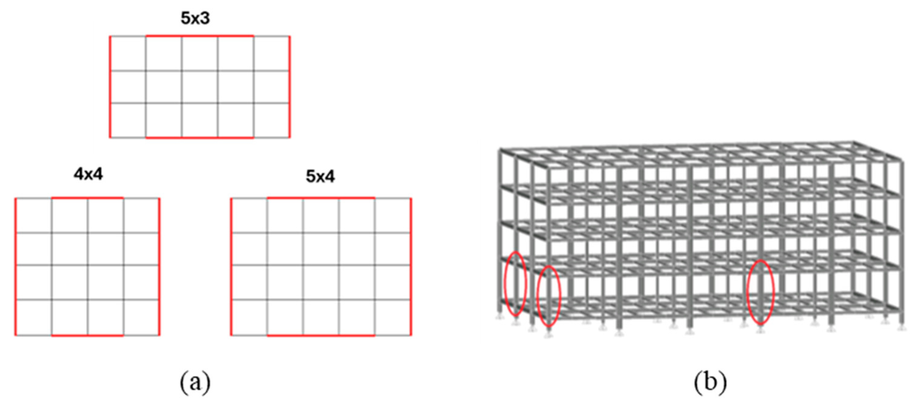
Figure 1. (a) Plan layout of structural archetypes; (b) column loss scenarios.
Buildings 15 02490 g001
Figure 2. Target (dashed lines), group average (bold blue dashed line), and single signal response spectra for Type 1 seismic action.
Buildings 15 02490 g002
Figure 9. Effect of damping on the displacement time histories of 6 m and 10 m span frames.
Buildings 15 02490 g009
Figure 10. Vertical displacement time history under different column loss scenarios: (a) 6 m and (b) 10 m span frames.
Buildings 15 02490 g010
Figure 11. Degree of plasticity of the directly affected zones (DOPDAZ) ratios under different column loss scenarios: (a) 4- and (b) 8-storey frames.
Buildings 15 02490 g011
Figure 12. DAZ members by column loss scenario—deformed shapes and stiffness of mobilised joints.
Buildings 15 02490 g012
Figure 13. Reserve Displacement Ductility of (a) bare steel frames (CN) and (b) frames with façade claddings.
Buildings 15 02490 g013aBuildings 15 02490 g013b
Figure 14. Ductility demand-to-capacity ratios for (a) 4-storey frames and (b) 8-storey frames.
Buildings 15 02490 g014
Figure 15. Displacement time-history comparison between initially undamaged (IU) and post-seismic (PS) column loss: (a) façade column loss for the N4-H3-S6-CN-T5×4-DE frame and (b) corner column loss for the N4-H4-S10-CN-T5×3-DE frame.
Buildings 15 02490 g015
Figure 16. Chord rotational demand ratios between initially undamaged (IU) and post-seismic (PS) scenarios: (a) façade column loss (LL) and (b) corner column loss (LC).
Buildings 15 02490 g016
Table 1. Parameters of variation.
Parametric VariableAdmissible Values
(N) Number of storeys4; 8
(H) Interstorey height3 m (3.5 m between gr. and 1st floor);
4 m (4.5 m between gr. and 1st floor)
(S) Bay span6 m; 10 m
(C) Façade claddingsNone (N); brick masonry (M—for wind-designed frames);
Cold-formed steel “X” bracing (C—for seismically designed frames)
(T) Bay plan layout3 × 5; 4 × 4; 5 × 4
(D) Lateral force design scenarioWind-designed (W); seismic- + wind-designed (E)
(L) Column removal scenarioXZ façade (L); XY façade (S); corner (C)
Table 2. Gravity loads.
Type of LoadLocationValue
Permanent structural loadAll storeys1.7 kN/m2
Permanent non-structural loadGround floor1.2 kN/m2
i-th floor1.4 kN/m2
Roof1.2 kN/m2
Live loadsGround floor4.0 kN/m2
i-th floor3.0 kN/m2
Roof0.4 kN/m2
Table 3. Records for Type 1 seismic action spectral matching—general characteristics.
Signal
Designation
Earthquake
Name
YearMagnitudeStation NameStation Soilvs,30 [m/s]
T1-1Tabas, Iran19787.35Dayhook659.6
T1-2Loma Prieta19896.93SF—Diamond Heights582.9
T1-3Chi-Chi, Taiwan19997.62ILA064375.3
T1-4Coyote Lake19795.74San Juan Bautista, 24 Polk St370.8
T1-5Chi-Chi, Taiwan19997.62TCU072468.1
T1-6Coalinga-0119836.36Parkfield—Gold Hill 2W376.1
T1-7Chi-Chi, Taiwan19997.62TCU046465.6
T1-8Chi-Chi, Taiwan-0619996.30CHY035473.9
T1-9—Chi-Chi, Taiwan-0319996.20TCU138652.9
T1-10Chi-Chi, Taiwan19997.62HWA035473.9
Disclaimer/Publisher’s Note: The statements, opinions and data contained in all publications are solely those of the individual author(s) and contributor(s) and not of MDPI and/or the editor(s). MDPI and/or the editor(s) disclaim responsibility for any injury to people or property resulting from any ideas, methods, instructions or products referred to in the content.