1. Introduction
The documentation of existing tunnels in Lithuania remains limited, primarily due to the diversity of their ownership, intended functions, and the lack of comprehensive research. To date, detailed descriptions are predominantly available only for tunnels associated with transportation infrastructure. The scarcity of tunnels across the country can largely be attributed to Lithuania’s predominantly flat topography, which reduces the necessity for such structures [
1]. In 1854, a team of engineers conducted a feasibility study to evaluate potential transportation routes and proposed several railway alignments [
2]. Following a detailed assessment of the Lithuanian landscape, the decision was made to construct two railway tunnels—one in Kaunas [
3,
4] and another in Paneriai [
5].
The concept of establishing a metro system in Vilnius, the capital of Lithuania, remains under consideration but has yet to be implemented. One of the primary challenges facing urban transportation in Vilnius is the extensive urban sprawl, which conflicts with the principles of a compact city development strategy [
6]. Ensuring the sustainable evolution of the city’s transport infrastructure is imperative [
7,
8,
9]. Furthermore, any future metro development must rigorously account for the preservation of cultural and historical assets, including maintaining safe distances between subway lines and heritage structures [
10]. Located in the historic center of Vilnius—designated as a UNESCO World Heritage Site since 1994 [
11,
12]—are two of the city’s most prominent landmarks: the Vilnius Cathedral [
13,
14] and Gediminas Hill, which contains the remains of the Upper Castle [
15]. A short passenger funicular, approximately 75 m in length, is currently operational on Gediminas Hill [
16]. The crypts beneath the Vilnius Cathedral remain in active use for religious and cultural purposes [
17], while the historical tunnels within Gediminas Hill [
15] have been backfilled with soil and are presently inaccessible to the public.
When comparing historical and contemporary approaches to the design of underground structures, it becomes evident that current practices benefit significantly from advanced computational tools and specialized construction technologies. Modern design processes are supported by sophisticated software and simulation environments, enabling engineers to model complex geotechnical and structural interactions with high precision. In this context, the ability to make informed decisions amid a multitude of variables and data sources has become increasingly valuable. Machine learning (ML) algorithms, which are gaining popularity in engineering applications, offer promising support in decision-making processes [
18,
19,
20]. For example, in [
18], ML techniques were applied to optimize mesh generation for numerical modeling, recommending an optimal finite element size of 1.4 m for soil settlement analysis. However, in cases where detailed fracture behavior is of concern, significantly smaller element sizes may be warranted. This is supported by findings from other studies [
21], which suggest that finer discretization is necessary to accurately capture localized stress concentrations and discontinuities. In addition to finite element methods (FEM), the discrete element method (DEM) can also be employed to assess the mechanical behavior of materials surrounding tunnel structures. DEM is particularly useful for modeling discontinuous and fractured material; however, it is computationally intensive, often requiring significantly more processing time compared to FEM-based analyses [
22]. The material surrounding a tunnel is typically located within a damage zone, which forms as a result of excavation-induced stress redistribution. The extent of this zone can reach up to 1.5 times the tunnel diameter, depending on geological and construction conditions [
23]. Moreover, the influence of dynamic disturbances—such as seismic activity or construction vibrations—can further exacerbate the extent and severity of the damage zone [
24]. Given these considerations, the investigation and implementation of protective measures to shield tunnel structures from external mechanical and environmental factors are of critical importance [
25]. Recent research has provided valuable insights that support the advancement of underground construction technologies and project management practices [
26,
27]. A thorough evaluation of environmental impacts is essential for accurately assessing safety levels in underground engineering projects [
28]. For instance, when considering internal pressures, the findings from [
29] indicate that the pore water pressure stabilizes approximately five seconds after loading. This rapid increase can significantly reduce the slope stability coefficient, potentially bringing it below unity under certain conditions. It is important to note that slope stability is influenced not only by groundwater but also by surface loads. Studies have shown that the mass of frozen snow can increase by up to 50% [
30], thereby exerting additional pressure on slopes and structures. As such, the inclusion of the snow load as a variable in stability assessments is warranted. Possessing advanced design software alone is insufficient; it is equally critical to evaluate complex, project-specific scenarios within the modeling environment. For instance, simulating fault dislocation within tunnel structures is essential for assessing the overall structural response under geomechanical stress conditions [
31]. Specialized fracture models can also be applied to analyze the behavior of roadway tunnels under varying loading and boundary conditions [
32]. Additionally, theoretical models developed to predict tunnel-induced ground settlement [
33] can be integrated into numerical simulations to enhance the predictive accuracy. Research has shown that structural settlement is influenced not only by the mechanical properties of the surrounding soil but also by the stiffness and structural configuration of the tunnel itself [
34]. Continued research and development in this field are imperative to ensure that engineering decisions are both technically sound and contextually appropriate.
This article focuses on a historically significant engineering case involving newly uncovered data related to the Gediminas Hill tunnel. In 2019, a previously undocumented tunnel was discovered beneath the remains of the western retaining wall, adjacent to the Castle-Keeper’s House. Unlike other known tunnels in the area, this structure has not been backfilled with soil and remains physically accessible. However, public entry is currently prohibited due to ongoing reconstruction and investigative activities. Preliminary investigations suggest that the tunnel may have been constructed in or after 1942, potentially by the German military during the Second World War. During the pre-reconstruction investigation of the Castle-Keeper’s House, structural monitoring revealed a displacement in the building’s upper southern corner. This observation prompted a detailed assessment of the potential influence of the recently discovered tunnel on the building’s structural behavior. Although the precise function of the tunnel remains unknown, two primary hypotheses have been proposed. The first suggests that the tunnel was intended to connect the Castle-Keeper’s House with the northern retaining wall, where a tunnel exit has been identified [
15]. The second hypothesis posits that the tunnel may have been constructed for military purposes—specifically, for the placement of explosives and subsequent flooding of the excavated area. This method was commonly employed during World War II to protect strategic infrastructure such as bridges [
35]. Explosives were used both to destroy bridges to impede enemy advancement and to prepare them for demolition in the event of capture. A further hypothesis suggests that the destruction of Gediminas Hill may have been intended as a symbolic act to undermine national morale. As a prominent cultural and historical landmark, the loss of Gediminas Hill could have been perceived as a blow to the spiritual identity of the Lithuanian nation [
36].
2. Previous Knowledge of the Gediminas Hill Tunnels
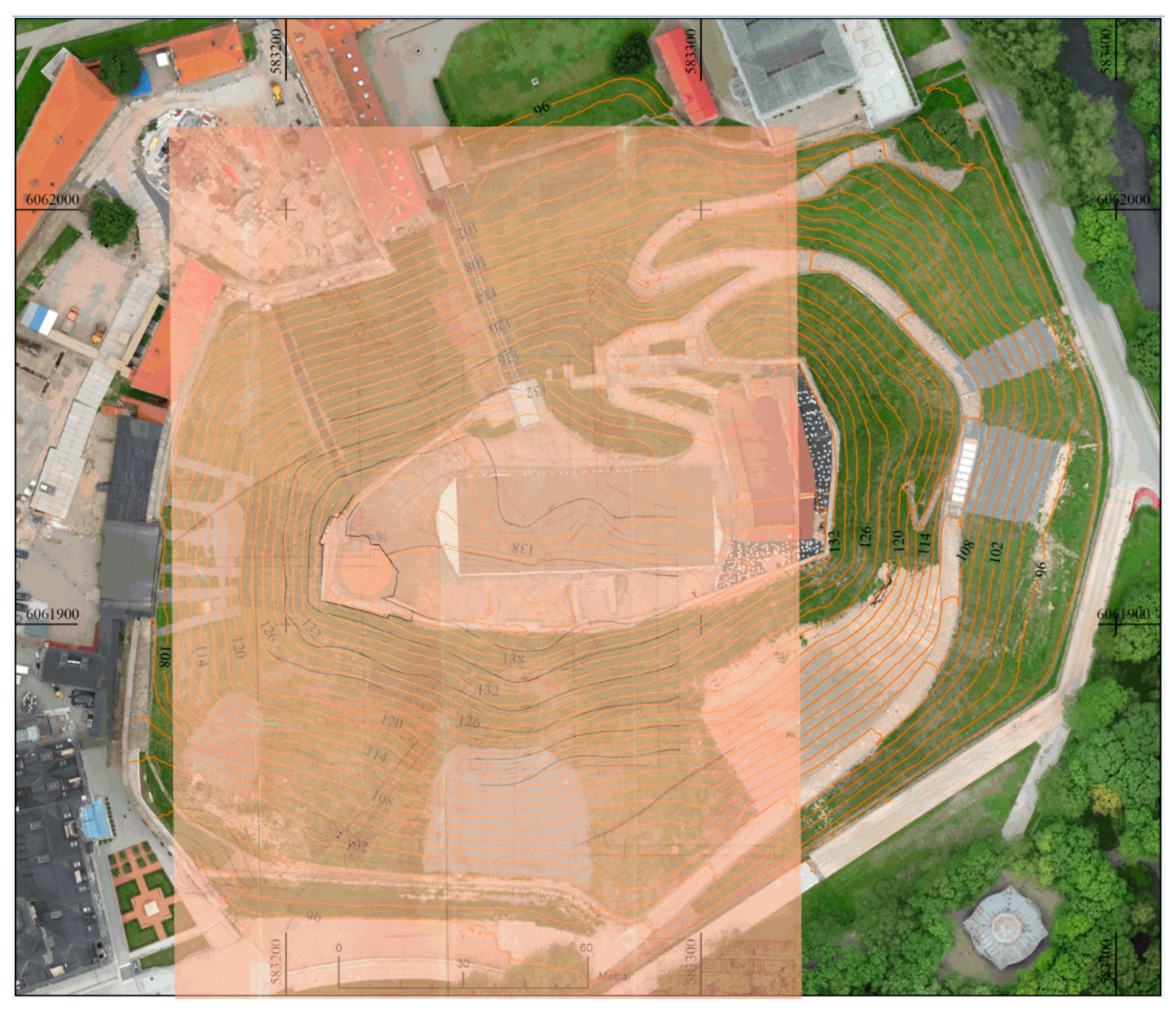
The precise date of the excavation of the Gediminas Hill tunnels remains unknown. Archival evidence from the Russian State Military History Archive indicates that brief references to the tunnels began to appear in the 19th century. However, detailed documentation is scarce. During the Second World War, between 1940 and 1944, the German military is believed to have constructed an anti-aircraft shelter within the hill. A historical tunnel layout, overlaid on the current topography, is presented in
Figure 1. The limited availability of archival materials—due to wartime destruction, document loss, or restricted access—continues to hinder a comprehensive understanding of the tunnel network beneath Gediminas Hill.
The tunnel featured internal dimensions of approximately 1.6 m in width and 2.0 m in height and included two known exits [
15]. One exit extended southwest toward Cathedral Square in Vilnius, with an estimated length of approximately 88 m. The second exit extended northwest, terminating within the northern remains of the retaining wall [
37], with a length of approximately 79 m. At both exit points, the tunnel was constructed using masonry, while the remaining sections were built using timber. The tunnel walls were supported by timber elements with a diameter of 0.25 m, and the ceiling was reinforced using a double-layered timber system composed of 0.20 m and 0.45 m elements. The total excavated cross-sectional dimensions of the tunnel were approximately 2.4 m in width and 3.0 m in height. Timber planks were used for the tunnel flooring. A vertical entrance shaft—also functioning as a ventilation portal—was constructed to a depth of 36 m from the hilltop, with a square cross-section measuring 3.6 × 3.6 m. This shaft was also built using timber construction techniques. Within the tunnel system, three operational zones were established, each with an area of approximately 36 m
2. These included a sanitary zone, a buffet area, a water supply section, and a ventilation equipment chamber. The tunnel network sustained damage and partially collapsed due to fire in 1948 [
11]. Subsequently, in 1960 [
11], all excavated tunnels and the ventilation shaft were completely backfilled with soil, the properties of which are summarized in
Table 1.
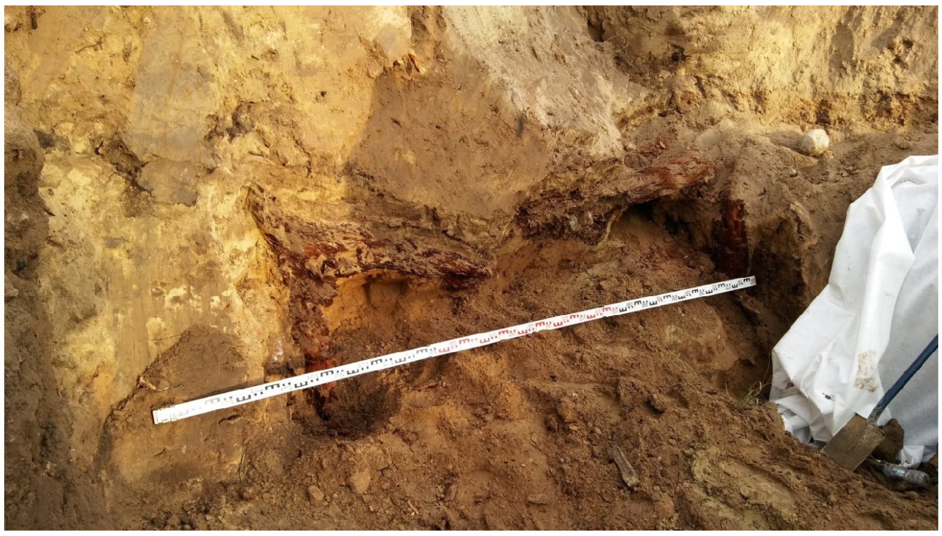
During the 2019–2020 investigations [
39], the southwestern tunnel exit was rediscovered (see
Figure 2). The primary timber support structure was found to be severely decayed and partially collapsed. As a result, the overlying soil above the timber ceiling had subsided slightly, with vertical displacements estimated between 0.2 and 0.4 m. Despite the structural degradation, a natural soil arch had formed above the deteriorated timber ceiling, temporarily maintaining the stability of the overburden.
3. Discovery of a New Tunnel Behind the Castle-Keeper Building
During structural investigations conducted in 2019 by the co-authors of this manuscript, a previously undocumented tunnel was discovered behind the basement of the Castle-Keeper building, beneath the western retaining wall. This finding is of particular significance, as the Castle-Keeper building dates back to the 16th–17th century [
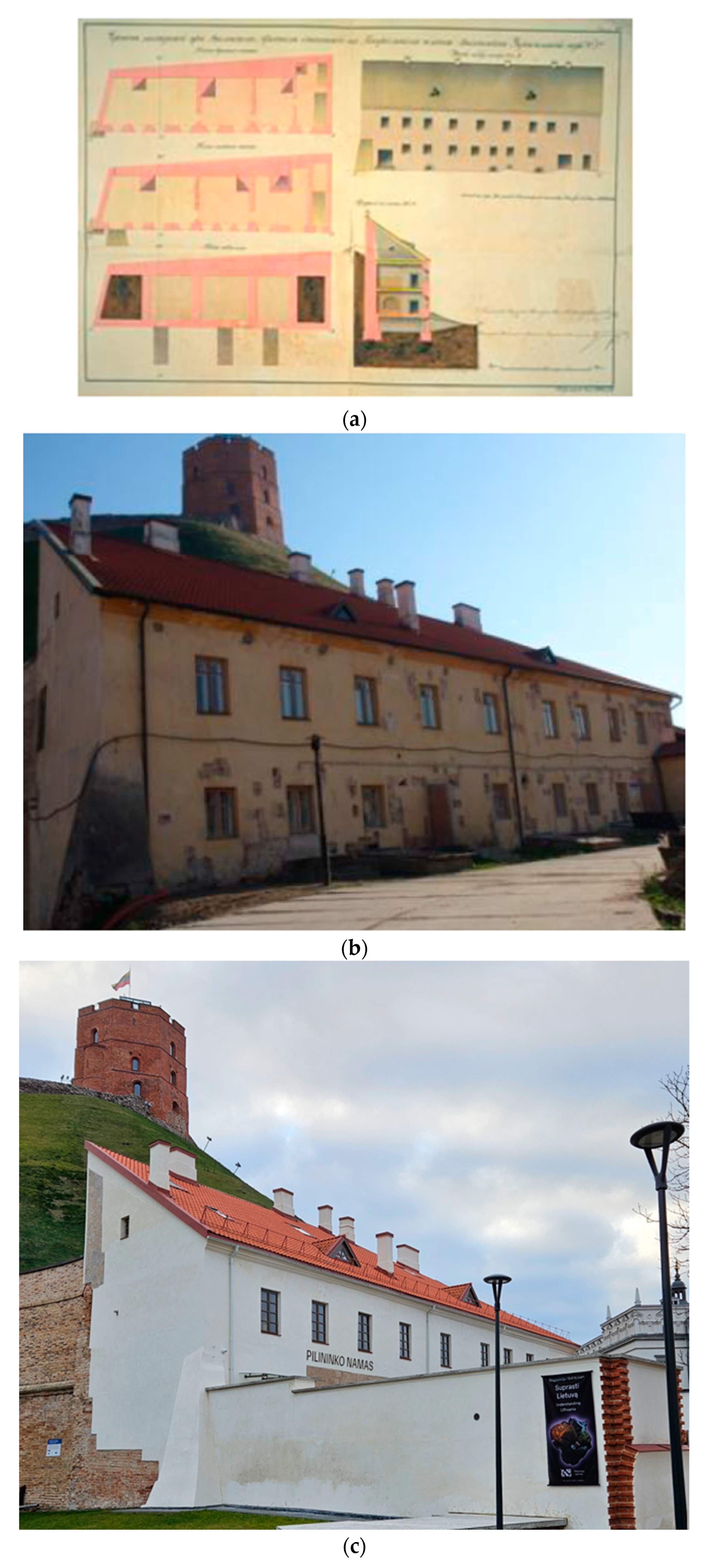
40]. According to architectural drawings prepared in 1832 (
Figure 3a), the western retaining wall was originally constructed at the same elevation as the basement foundations of the Castle-Keeper building. Comparative visual documentation of the building prior to and following reconstruction is presented in
Figure 3b and
Figure 3c, respectively.
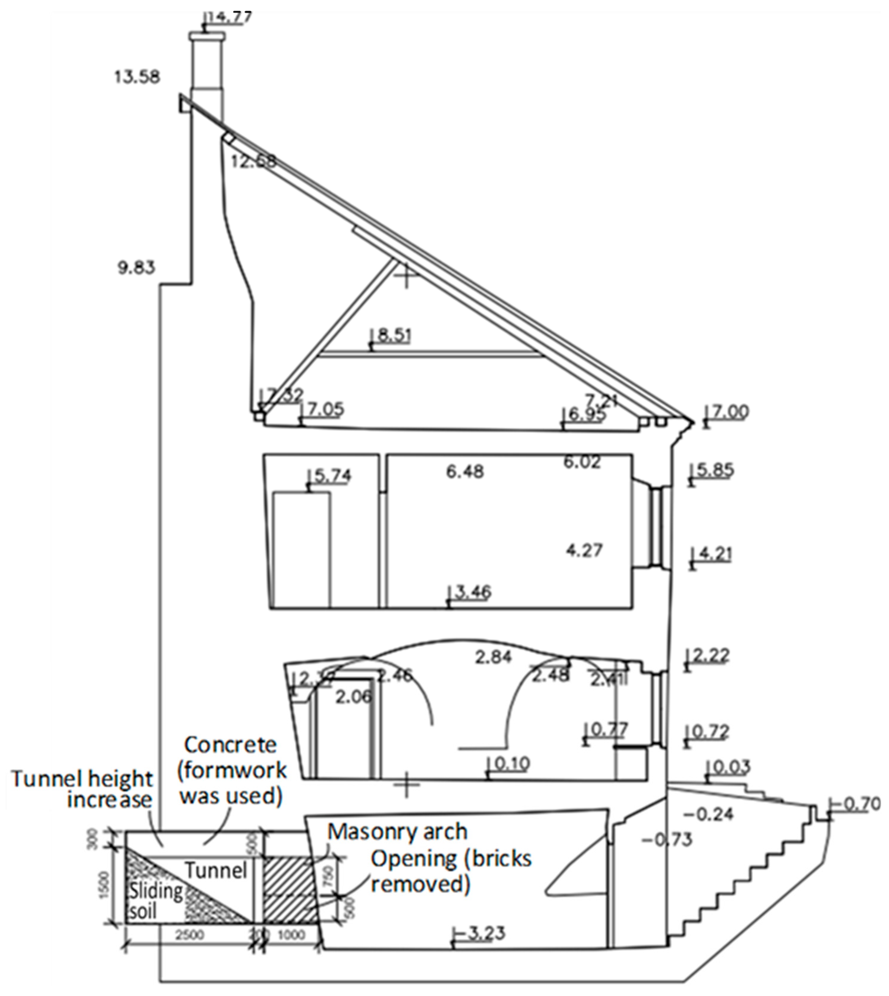
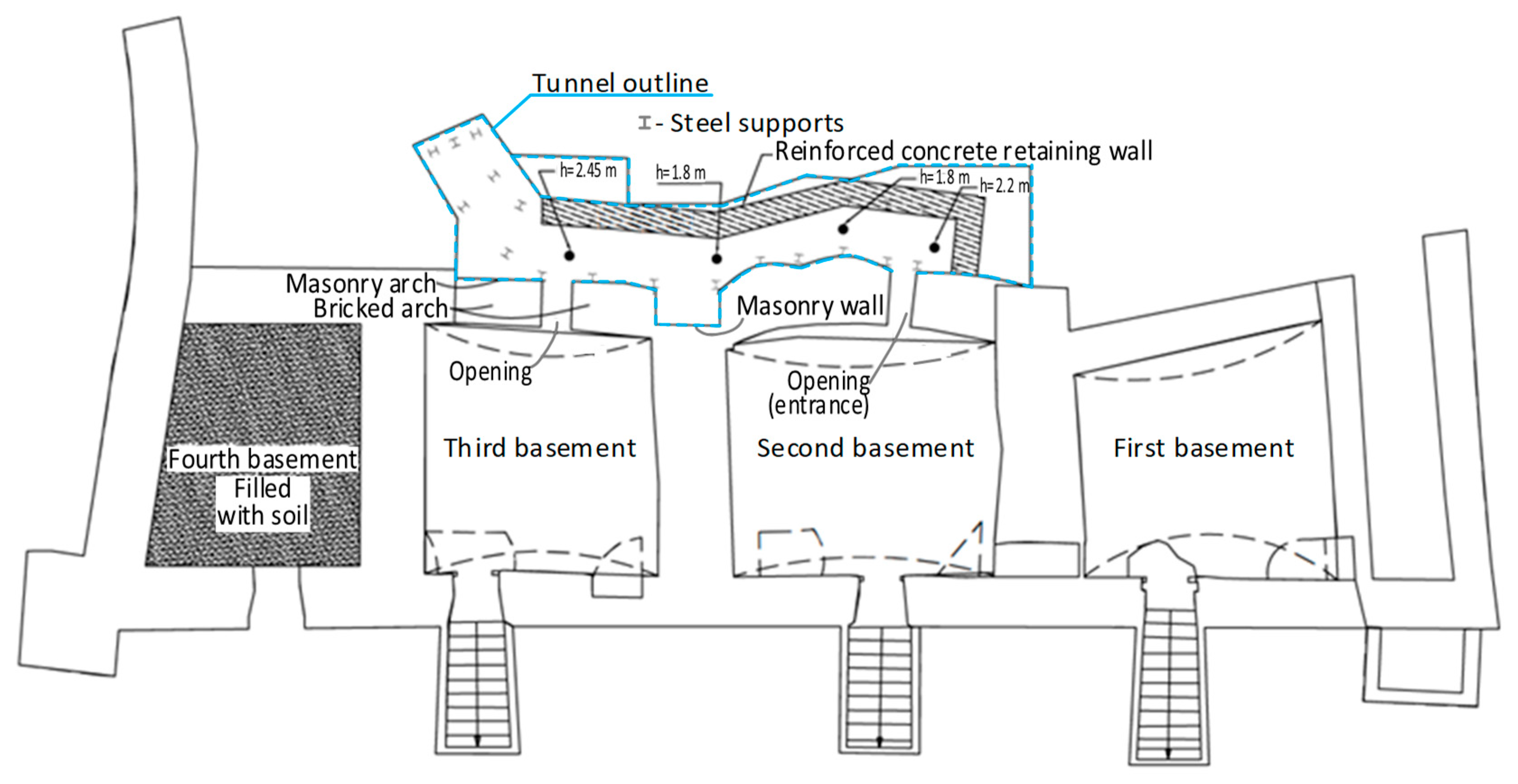
The newly identified tunnel beneath the western retaining wall originates from the basement of the Castle-Keeper building (
Figure 4). This discovery significantly alters the previously understood chronology of the retaining wall and the construction phases of the Castle-Keeper building. Contrary to earlier assumptions, it is now evident that the western retaining wall predates the construction of the Castle-Keeper building. Structural analysis indicates that the foundations of the Castle-Keeper building were inserted beneath the base of the western retaining wall, extending 1.5 to 2.3 m below it (
Figure 4). This suggests that the building was constructed incrementally by excavating a trench approximately 2.0 to 2.4 m wide and 2.4 m deep adjacent to the retaining wall, followed by the installation of masonry foundation elements (
Figure 5).
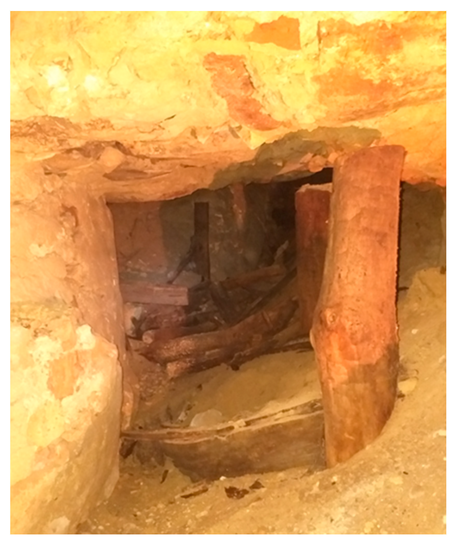
The tunnel located beneath the western retaining wall was originally constructed using timber supports, which were found to be completely decayed during the 2019 investigation. Only a few partially decomposed timber columns remained intact and were documented during the survey (
Figure 6). Notably, the tunnel lacked any form of internal retaining wall or lining. In
Figure 6, the masonry of the western retaining wall is visible at the top of the image (representing the base of the wall), while the partially collapsed internal soil is seen on the right. The basement foundations of the Castle-Keeper building are visible on the left. This configuration suggests that, over time, the absence of structural confinement allowed the surrounding soil to gradually migrate toward the retaining wall. The tunnel was excavated in sandy soil, the geotechnical properties of which are summarized in
Table 2.
In 2020, the tunnel beneath the western retaining wall was structurally reconstructed. However, it remains closed to the public due to ongoing archeological and engineering investigations. The reconstructed tunnel alignment is indicated in
Figure 5. Current research confirms that the tunnel was excavated during the Second World War. Nevertheless, its original purpose remains uncertain, and further interdisciplinary studies are required to clarify its intended function.
4. Tunnel Influence Assessment in a Numerical Model
The tunnel construction process and its influence on the structural behavior of the Castle-Keeper building were simulated using an enhanced numerical model, previously developed and described in [
42]. This model was validated using both earlier research findings [
42] and monitoring data [
15,
43]. The monitoring of surface and structural displacements on Gediminas Hill is conducted using an Internet of Things (IoT)-based system [
43]. This system comprises a network of sensors integrated with wireless communication and software control. Sensors are strategically placed across the hill, including on key structural elements, to capture real-time displacement data. The sensor layout and the recorded displacement measurements are detailed in the research of Guilhot et al. [
43]. The comparison between the model’s predictions and the observed monitoring data confirms the model’s accuracy and reliability in simulating soil-structure interaction and deformation behavior.
The commercial finite element software DianaIE [
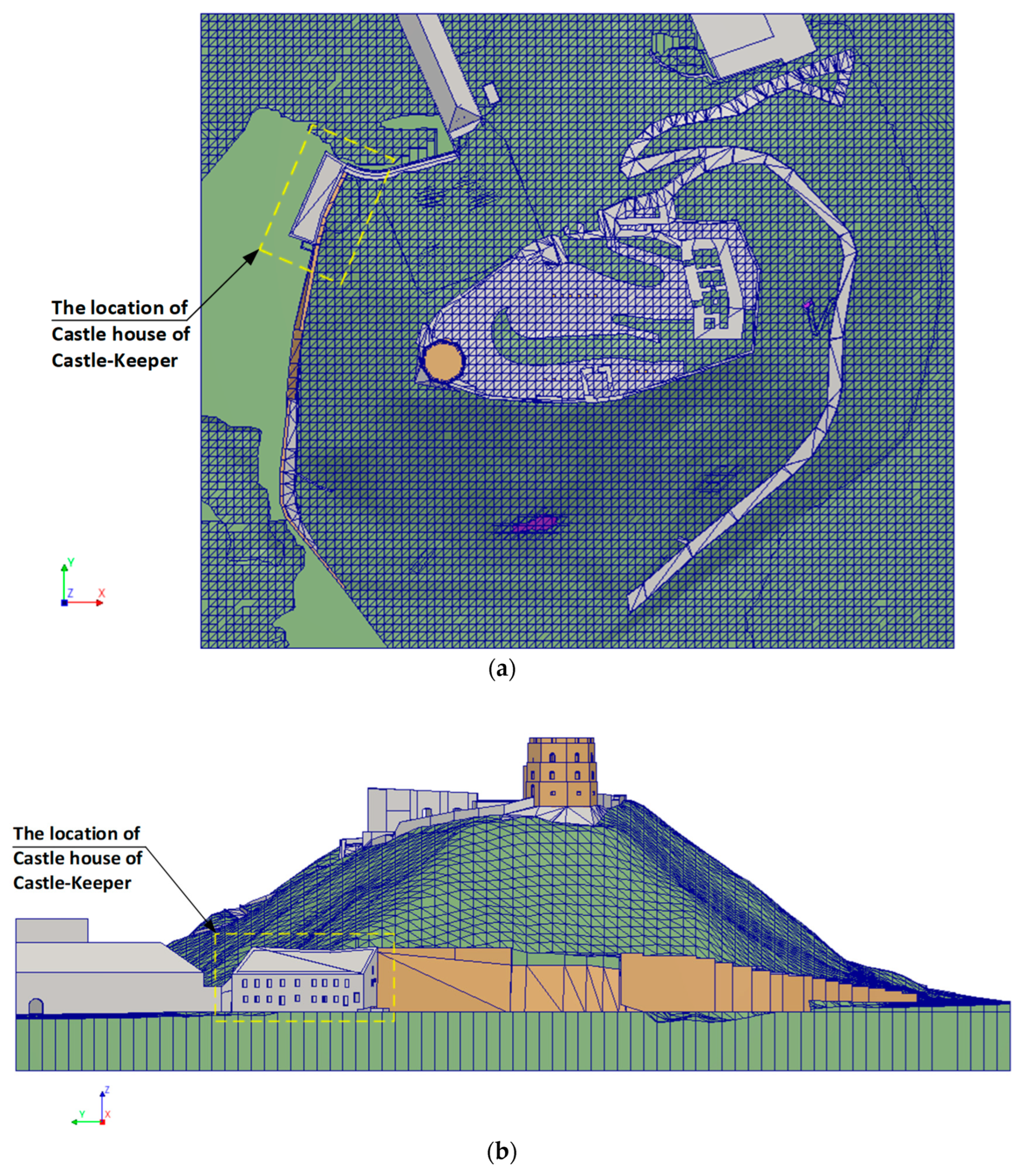
44] Release 10.6 was used for model analysis. The current numerical model of Gediminas Hill was developed using the finite element software DianaIE, selected for its advanced capabilities in phased construction modeling. This program is particularly well-suited for simulating complex geotechnical processes, including sequential excavation, structural staging, and time-dependent soil–structure interaction. The location of the Castle-Keeper’s House in the model is shown in
Figure 7a,b. In the numerical model, the tunnel space falls into the volumes of the Castle-Keeper’s House, the western wall, and the soil layer lgIIdn. Before tunnel construction, the tunnel volume is considered a filled volume. Thus, the soil pressure is taken over by the western retaining wall and the Castle-Keeper’s House, and equilibrium is established. When installing the tunnel, the area of the resisting retaining wall is reduced, which takes over the soil pressure. In addition, additional soil pressure arises due to the effect of the loosened soil mass. Because the loosened soil deforms under the influence of gravity, its mechanical properties also change. The impact of the soil on the western retaining wall increases. Since the Castle-Keeper’s House is supported by the western wall, it takes over part of the soil effect. Therefore, the analysis in the numerical model must be performed in stages, assessing the installation of the tunnel and the movement of the internal soil mass. The movement of the soil mass is assessed by reducing the cohesion and the angle of internal friction. The numerical analysis predictions of the finite element model are based on the results of the nearest geological–geotechnical investigations of the boreholes. The nearest investigation point is located on top of Gediminas Hill, and on the slope, only shallow geological–geotechnical investigations are provided, which allows a knowledge about the top soil layers of the slope [
41,
42].
The modeling assumptions applied in this study are based on the previously published work in [
42]. The current version of the numerical model has been slightly refined by incorporating the architectural features of the Castle-Keeper’s House, specifically by introducing door and window openings into the wall geometry. These modifications were implemented based on available architectural drawings, as structural documentation was not accessible. Material nonlinearity was considered only for the soil layers, while all structural components, including the Castle-Keeper’s House, were modeled using linear elastic material properties. Although the actual structures exhibit cracking and localized limit states, the absence of detailed material characterization data limited the ability to model these behaviors accurately. As a result, the structural representation in the model aligns more closely with architectural rather than structural performance criteria. A fully bonded (stiff) connection was assumed between the mesh nodes of the Castle-Keeper’s House and the surrounding soil. Interface elements were not included in the current model configuration.
The Mohr–Coulomb material model was accepted for soil, because geological–geotechnical engineering investigations are limited [
41], and other models [
45] cannot be applied based on the current quantity and quality of investigations. Comparison of the results with alternative models and methods [
45] is not possible for the sensitivity and validation of the model. For buildings and the remains, linear constitutive material models were used.
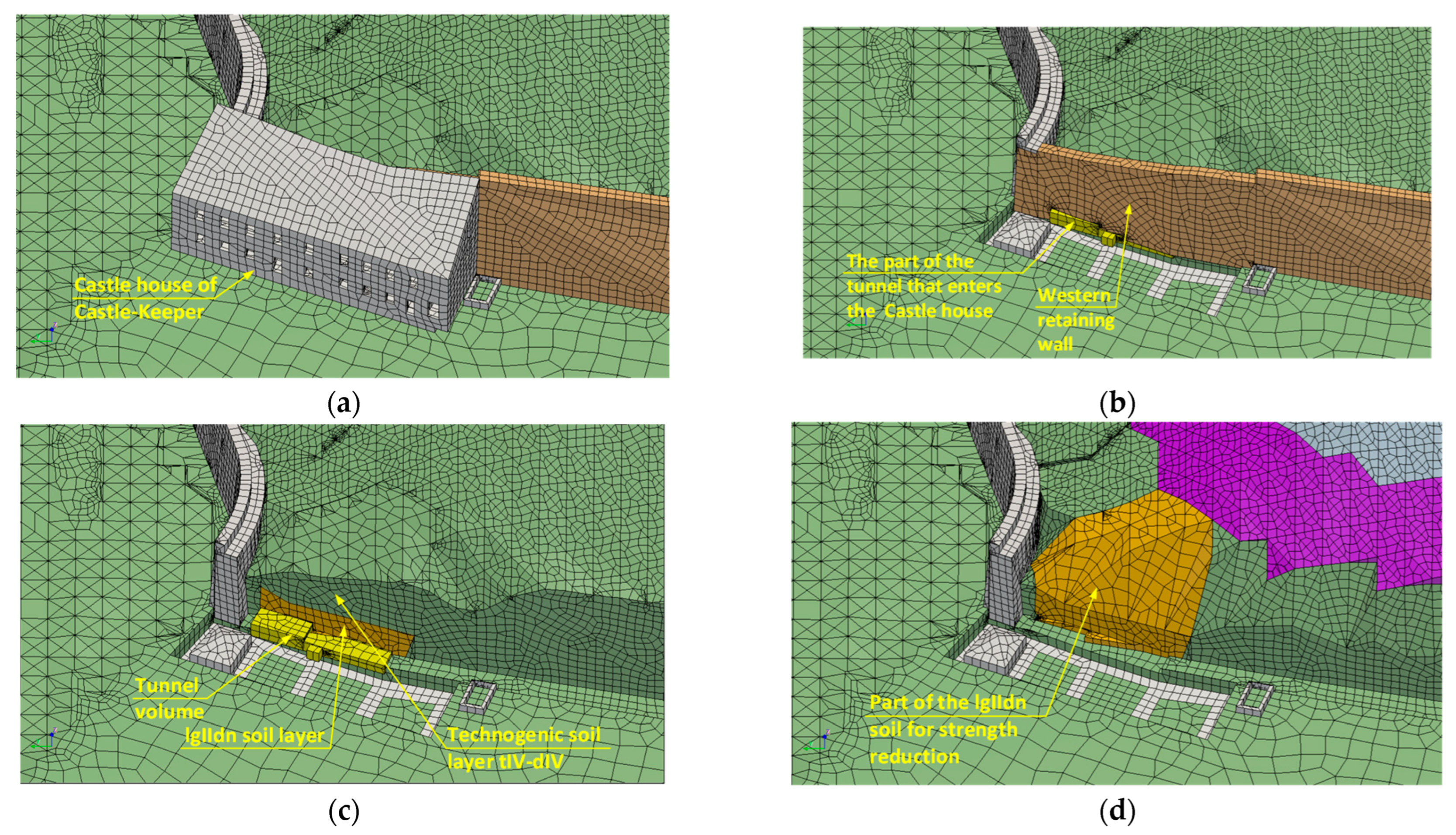
A phased analysis of the numerical model was performed. The initial soil stress was evaluated in the first phase. Then, in the second phase, the Hill is loaded with the load of the technogenic layer. In the third phase, the numerical model calculates the state when all the structures are installed. Then, an additional phase of calculations begins, in which the tunnel volume is eliminated. In this phase, the Castle-Keeper’s House loses part of its support, and the soil of the lgIIdn layer deforms under the influence of its own mass and gravity.
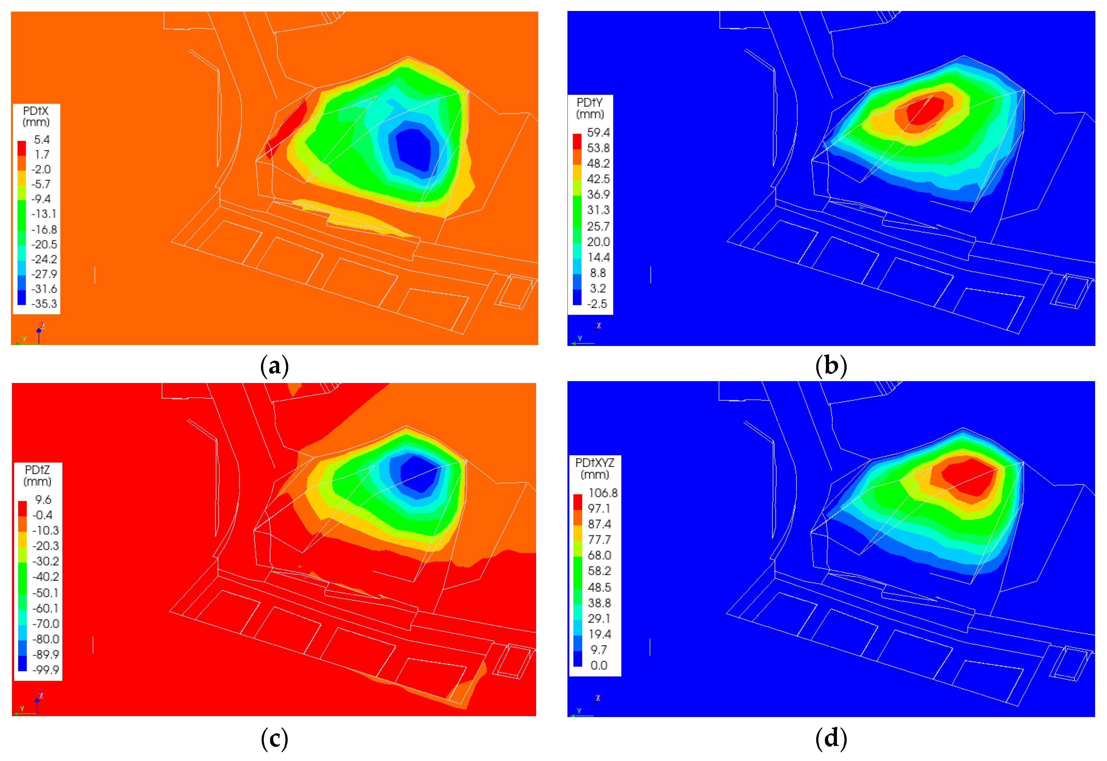
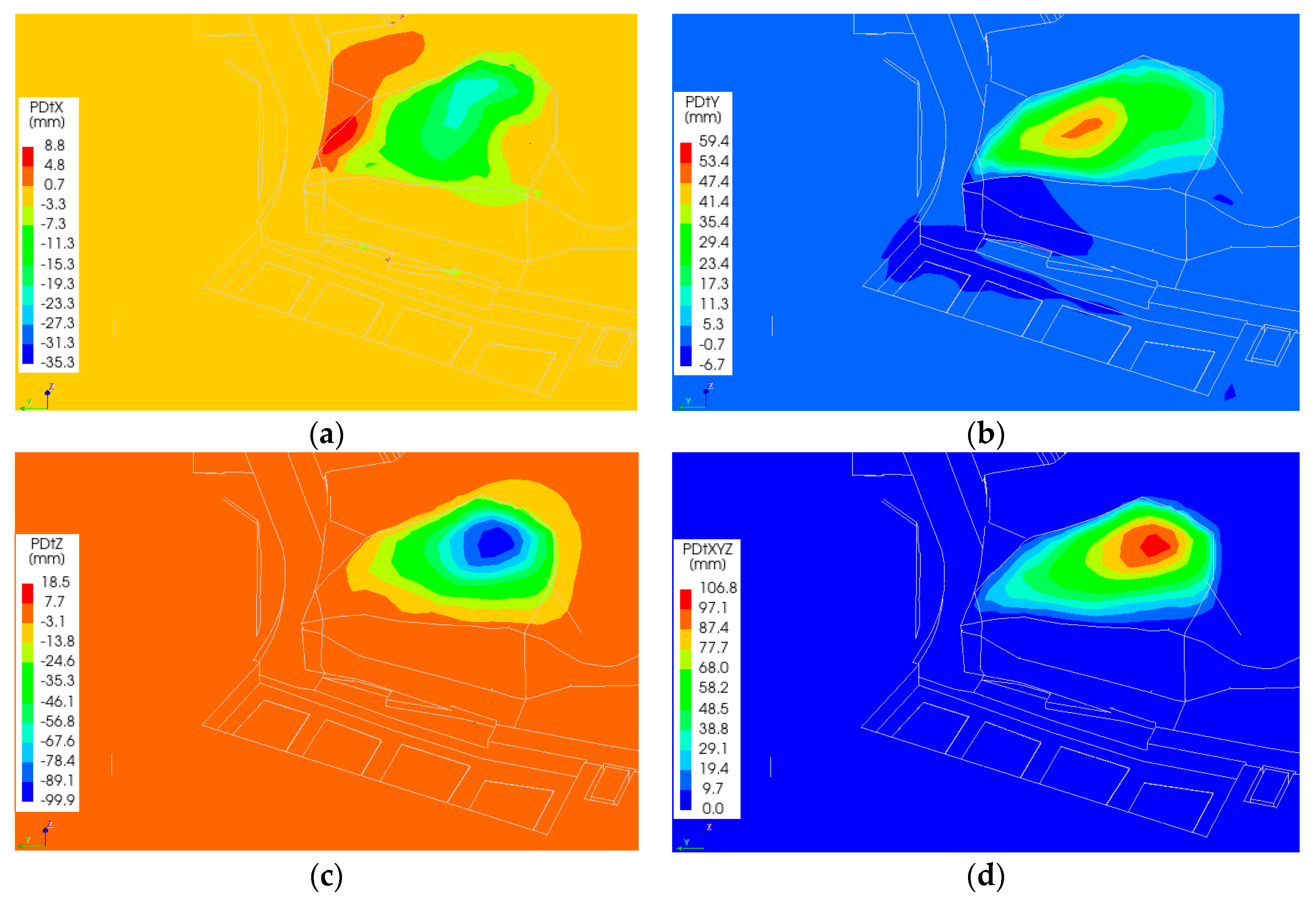
Figure 8 shows the objects that dominate in the additional phase: 8-a, Castle-Keeper’s House and the western retaining wall in the phase when all structures are involved; 8-b (the rendering of the Castle-Keeper’s House is disconnected), the tunnel volume (yellow) is visible, which falls into the volume of the Castle-Keeper’s House, and the retaining wall and the soil lgIIdn layer, which will be eliminated in the final phase; 8-c, the image of the western retaining wall is eliminated, most of the tunnel volume is exposed, and the volume of the soil lgIIdn layer above which the technogenic soil layer is visible; and 8-d, the volume of the soil lgIIdn layer, which creates additional pressure on the retaining wall and the Castle-Keeper’s House due to movement.
The iterative procedure was used in the nonlinear analysis to predict the behavior of the model. The self-weight or external load was increased by steps. Then, the total displacement increment with iterative displacement increments is used to reach the equilibrium. According to the FEA software manual [
44], the Quasi-Newton relation is used for the iterative displacement increment:
Here, —iterative displacement increment; —change in out of balance force vector; —secant stiffness matrix.
According to [
44], the inverse secant stiffness matrix is applied by the so-called BFGS (Broyden–Fletcher–Goldfarb–Shanno) method:
Then, the iterative displacement increment is:
Here, —out of balance force vector.
Despite the fact that the linear set of equations is solved, the increment of displacements at each load increment is not the same, and the distribution of displacements is not linear. The numerical model forms a statically unsolvable system. Therefore, the displacements of the retaining wall, soil, and building depend on the overall stiffness matrix. The material parameters required for the stiffness matrix are presented in
Table 3.
The self-weight load of the soil and structures is evaluated through acceleration and the geometry provided with density, by introducing the value of the acceleration of gravity of 9.81 m/s2. Since the calculations were performed in phases, involving different sets of finite elements, the displacements when moving from one phase to another depend on the new stiffness matrix. When assessing the decrease in soil mechanical parameters (Mohr–Coulomb and Drucker–Prager plasticity parameters, cohesion, and the friction angle), the reduced stresses in the soil are calculated to find the residual force for equilibrium and displacements. The calculations continue until the final equilibrium is reached.
Groundwater flow plays a critical role in the assessment of slope stability. The permeability characteristics of the geological strata within Gediminas Hill have been extensively documented in [
15], indicating that the hill is predominantly composed of low-permeability (impermeable) layers. Additionally, the hill is equipped with a water collection and drainage system designed to control surface and subsurface water. As a result, a portion of the infiltrating water is redirected through the overlying technogenic layer, while the remainder is discharged via the engineered drainage infrastructure. Despite the importance of groundwater dynamics, the current numerical model does not incorporate groundwater flow analysis. However, the influence of the pore water pressure and associated stress increments is recognized as a significant factor in slope behavior. Therefore, the integration of groundwater flow modeling is planned for future research phases to enhance the accuracy and comprehensiveness of slope stability assessments.
5. Impact of Tunnel Construction
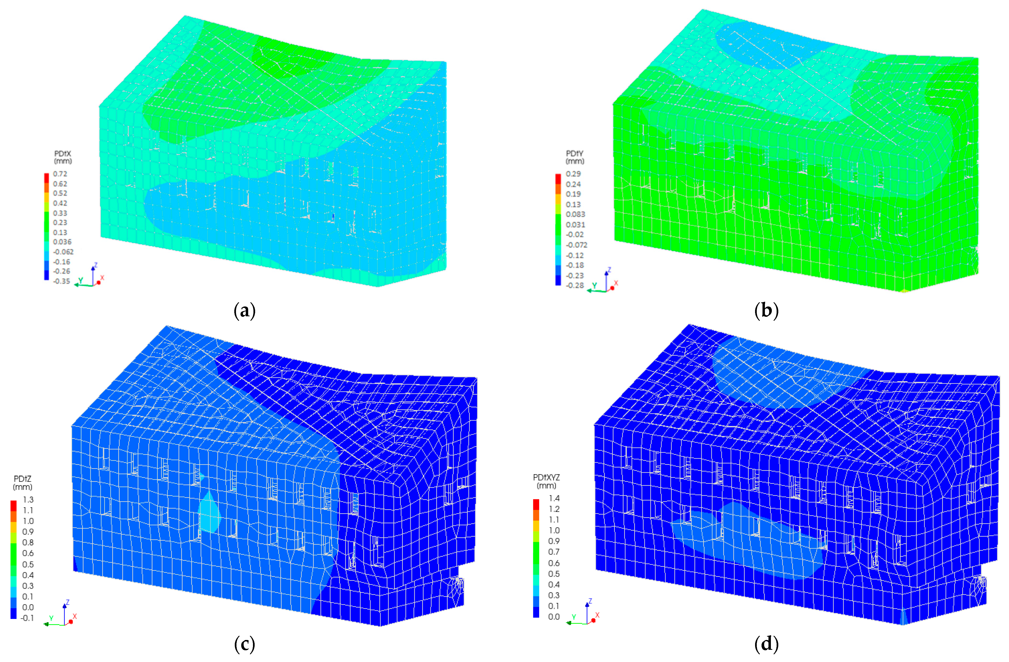
The Castle-Keeper building is structurally connected to the western retaining wall through its transverse masonry walls. As a result, the building’s behavior is directly influenced by soil displacements along the slope, which exert lateral pressure on the retaining wall. Numerical simulations indicate that when a tunnel segment is introduced within the retaining wall, the top of the wall displaces in the direction opposite to the applied soil pressure. Accordingly, the Castle-Keeper’s House experiences a rotation, and the displacement of its top follows the displacement of the western retaining wall. The most significant displacement development is concentrated at the tunnel construction zone (see
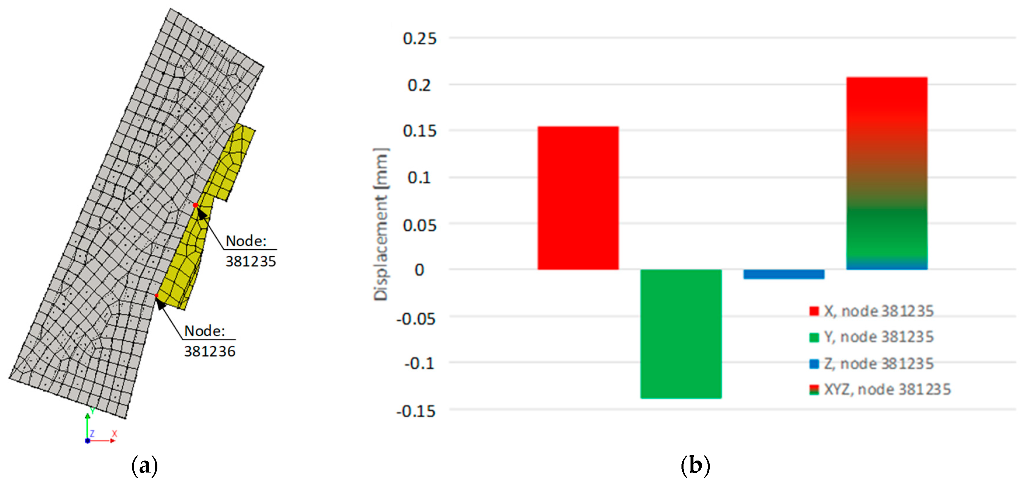
Figure 9). Notably, the areas of maximum displacement in the numerical model correspond closely with those identified through long-term structural monitoring. To validate this correlation, a specific node—node 381235—was selected from the numerical model. This node corresponds to the upper corner of the building where the monitoring data had previously indicated displacement. The simulation results show that this node experienced displacement along a predominantly horizontal trajectory (
Figure 10). Analysis of the displacement vector in the XYZ coordinate system confirms that the top of the building moved in the direction opposite to the ground pressure, consistent with the observed structural behavior.
The deformation behavior of the Castle-Keeper building during the tunnel installation phase, as predicted by the numerical model, does not align with the displacements observed during the pre-reconstruction investigations. The simulation results indicate that the most significant displacements occur in the vicinity of the tunnel alignment. In contrast, field investigations identified notable displacements at the southern corner of the building. Based on this discrepancy, it can be concluded that the tunnel installation is unlikely to be the primary cause of the observed displacement at the southern corner. This suggests that additional factors may be influencing the soil–structure interaction in that area. Consequently, further analysis is required to assess the soil displacement mechanisms and their potential contribution to the building’s deformation.
6. Impact of Soil Displacement
The primary structural system of the Castle-Keeper’s House is composed of load-bearing brick masonry. The masonry construction extends from the basement level, forming both longitudinal and transverse walls, as well as arched basement ceilings. Due to the uniform distribution of the soil pressure across the structure, the primary resistance is provided by the transverse masonry walls. These walls exhibit variable thickness along the vertical axis of the building. Despite the presence of openings in both the internal and external walls (e.g., doors and windows), the interconnection between the transverse and longitudinal masonry walls establishes a rigid structural framework. This configuration effectively redistributes internal loads to the foundation system. Numerical modeling evaluations reveal that the building is founded on a soil layer classified as lgIIdn. At the basement level, the thickness of the brick walls reaches up to 1.5 m. Additionally, the first basement room is backfilled with soil, further enhancing the overall stiffness of the structure. Timber elements are utilized exclusively in the construction of the ceiling and roof systems. Their contribution to the global stiffness of the building is considered negligible.
The tunnel is installed approximately at the basement level. Therefore, the soil pressure is distributed approximately at the first-floor level. Looking at the position of the tunnel in the building plan (
Figure 5), its center is located on the transverse wall of the building. Again, the tunnel is cleverly designed, as most of the ground pressure should fall on it. The vector of the soil mass movement is directed toward the transverse wall, which extends vertically up to the second floor. From a structural standpoint, this configuration suggests that the building should exhibit relatively uniform deformation. However, the distribution of deformations along the length of the building is not uniform (
Figure 11 and
Figure 12). This could have been influenced by the filling of the first tunnel, which partially stiffens the building frame, because at that place, the load is transferred to the foundation over a larger area.
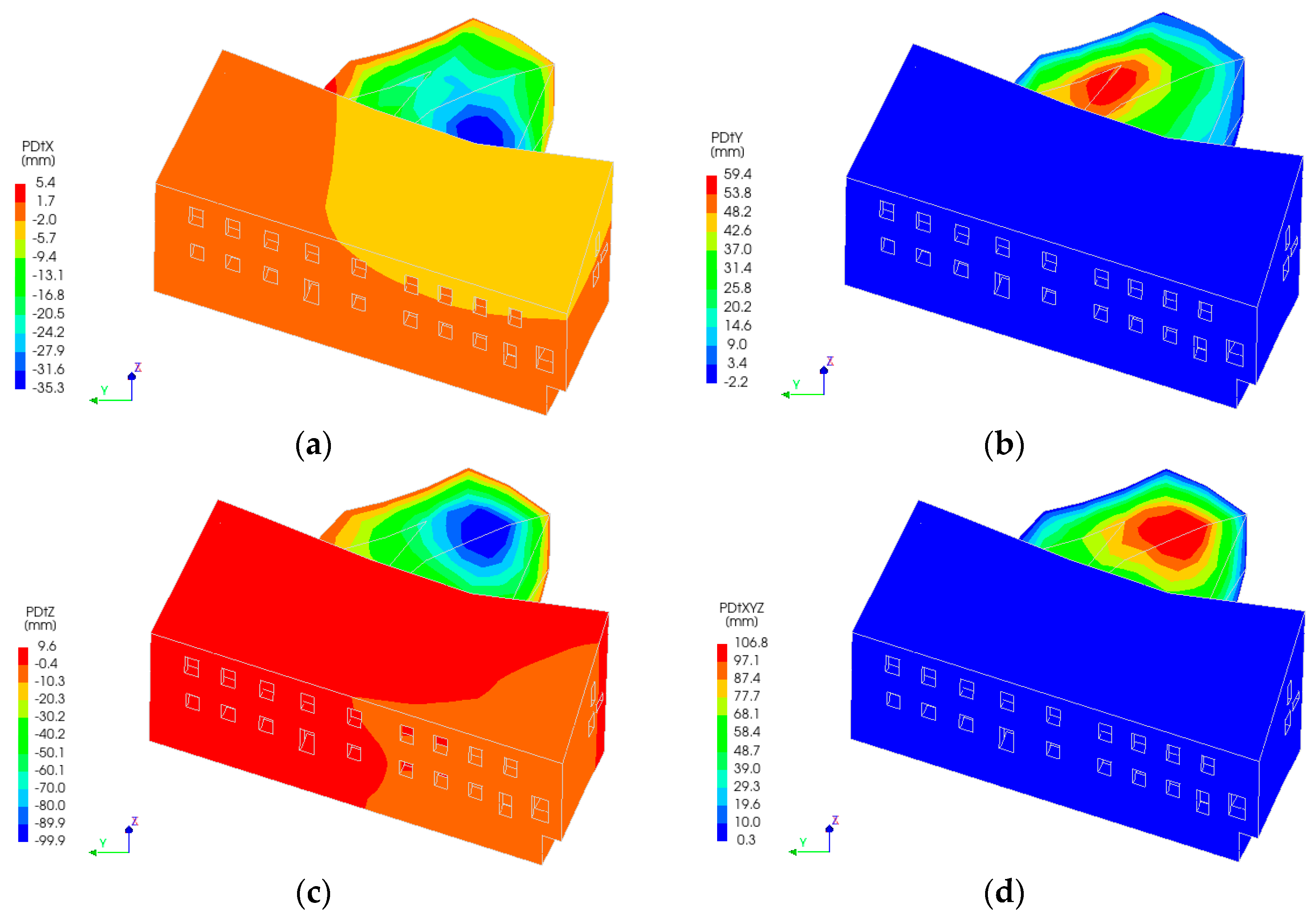
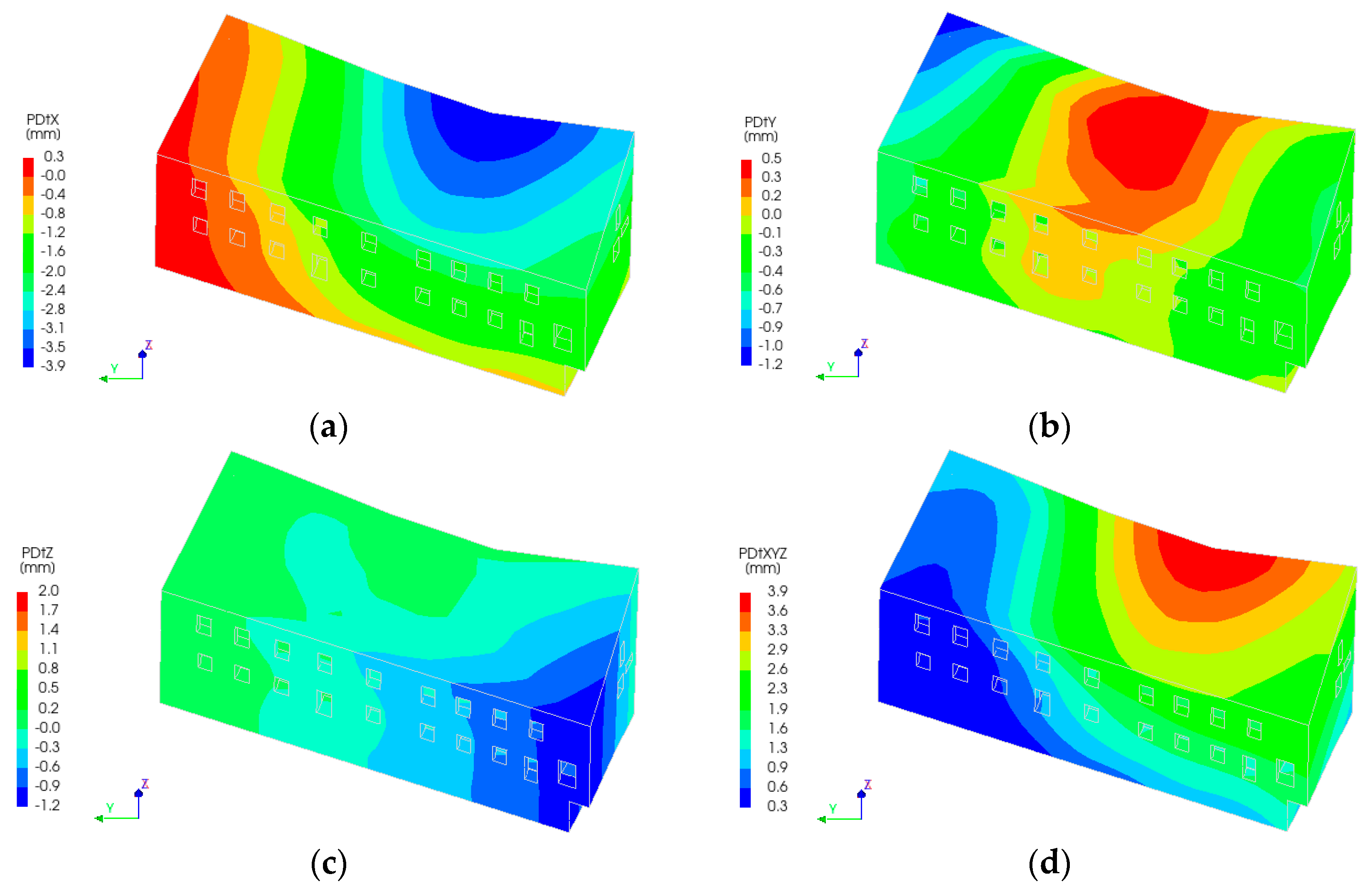
The displacement pattern of the soil mass above the tunnel indicates that the most significant movement within the lgIIdn soil layer occurs near the western wall, as the tunnel is embedded within this stratum. In contrast, the center of mass movement within the overlying technogenic layer is located farther from the western wall compared to that of the lgIIdn layer. The thickness of the lgIIdn layer in proximity to the western wall ranges from 3.73 to 4.76 m, and due to its higher density and mass relative to the technogenic layer, it exhibits greater displacement (see
Figure 13). The technogenic layer, with a thickness varying between 1.36 and 8.35 m, possesses a lower mass, and its deformation is primarily governed by the displacement behavior of the underlying lgIIdn layer. Consequently, the technogenic layer undergoes less movement (see
Figure 14), resulting in a reduced impact on the western wall.
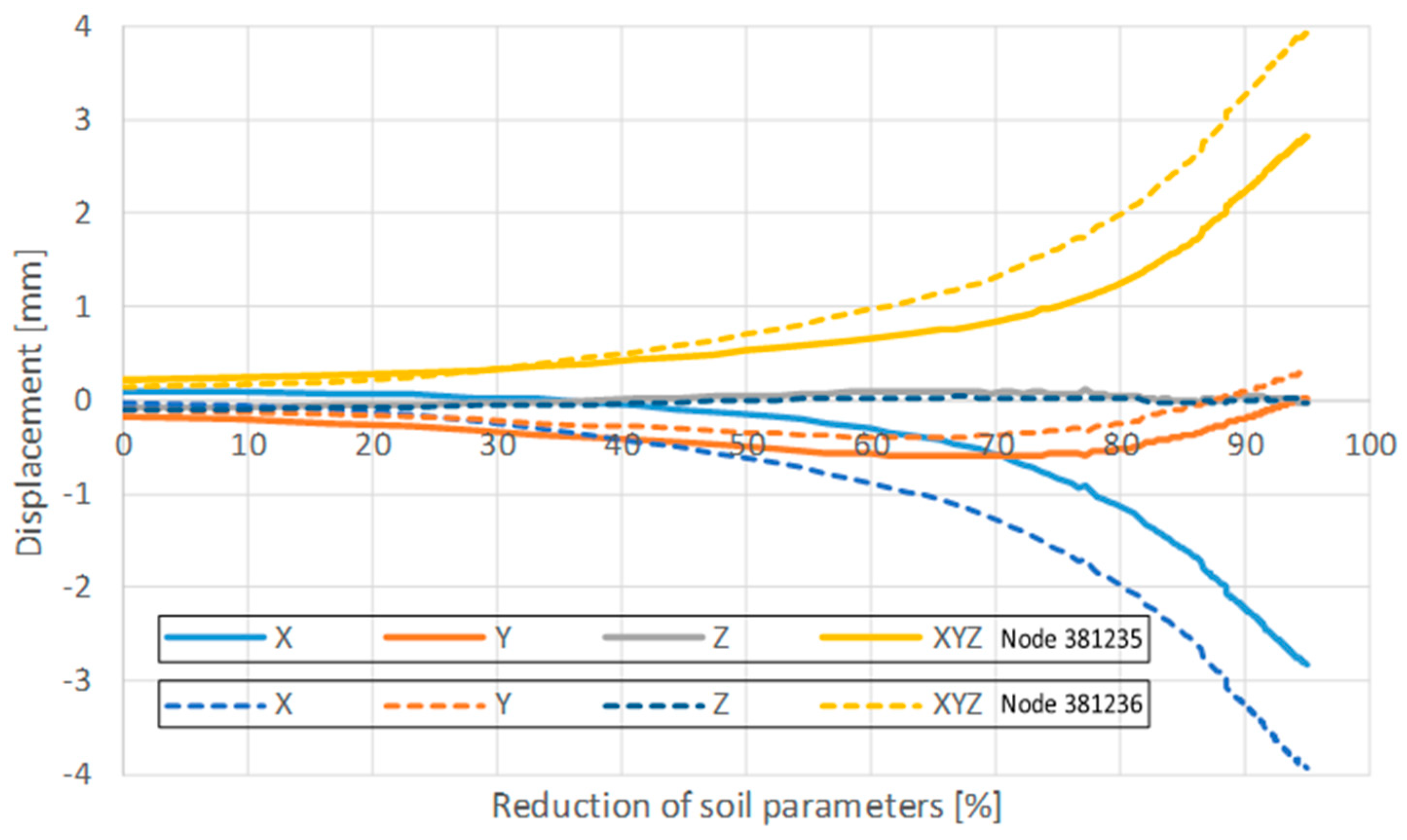
Following the assessment of soil mass displacement, corresponding deformations in the Castle-Keeper building were observed. Analysis of nodal displacements—specifically nodes 381235 and 381236 (refer to
Figure 10)—during the tunnel construction phase revealed that node 381236 experienced greater displacement (see
Figure 15). A comparative evaluation of the displacement progression in the Castle-Keeper structure and the internal ground mass indicates an elastic interaction between the two systems. In the majority of computational iterations, the displacement ratio between the building and the underlying soil mass stabilized at approximately 0.1. This implies that the structural displacement of the Castle-Keeper building reached approximately 10% of the internal soil displacement, suggesting a predominantly elastic response under the given loading conditions.
This pattern of displacement evolution aligns more closely with the behavior observed during the pre-reconstruction investigation. The center of mass of the soil changes its position, and the pressure is distributed differently on the retaining wall.
Figure 13 shows that the displacement development zone is closer to the southern edge of the Castle-Keeper’s House. Therefore, assessment of the soil mass movement allowed for better results.
Numerical modeling enables a more precise evaluation of potential structural and geotechnical consequences. The development of a digital twin facilitates the assessment of various engineering interventions on both the pre-renovation and post-renovation states of the structure. This approach significantly contributes to the long-term preservation of culturally significant heritage assets. Decision-making can be chaotic [
36] during the existence. Looking to the past and the future can help us make better decisions.
