
Flexural Behavior of Pre-Tensioned Precast High-Performance Steel-Fiber-Reinforced Concrete Girder Without Conventional Reinforcement: Full-Scale Test and FE Modeling

Abstract
1. Introduction
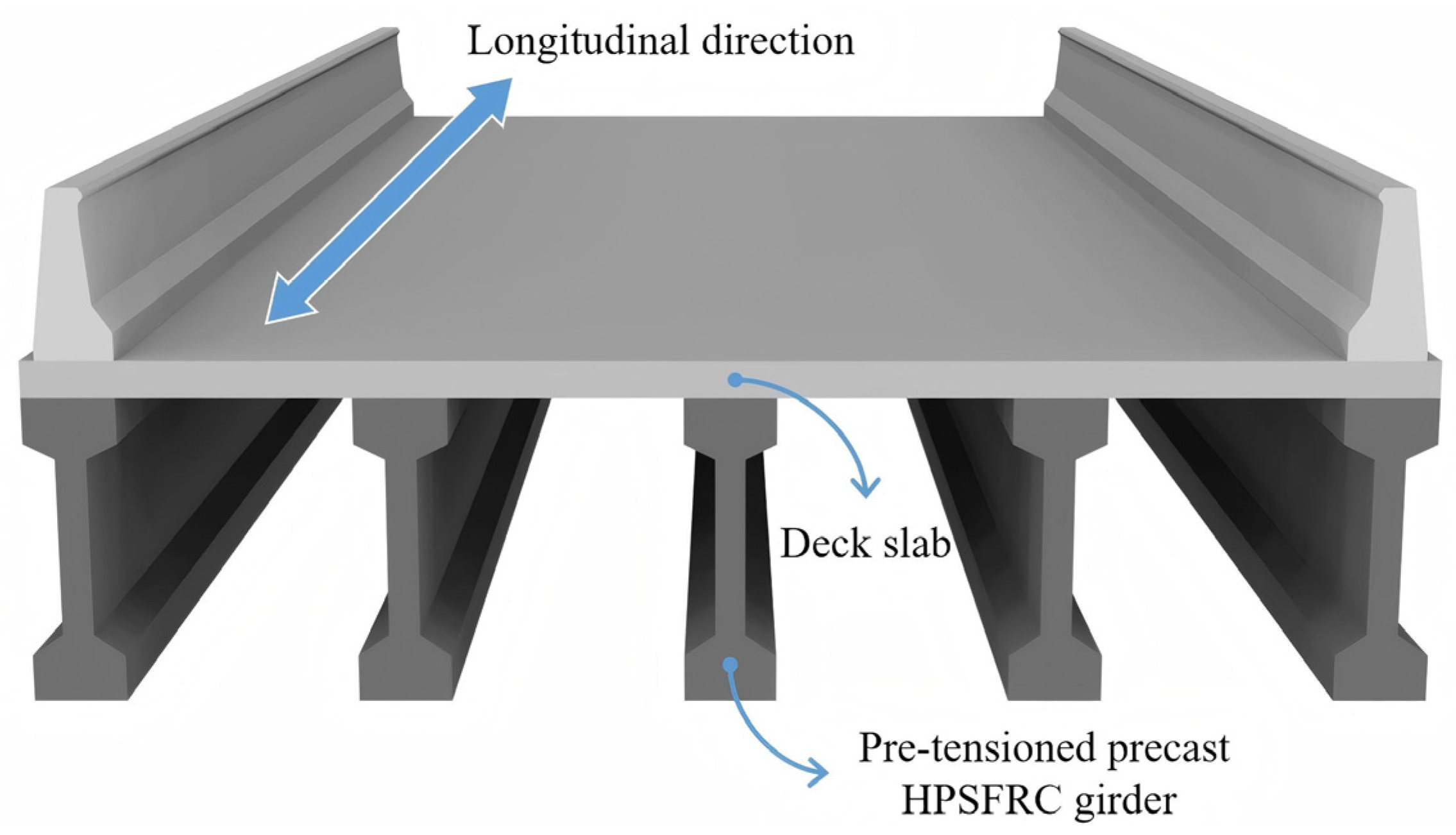
2. Engineering Background
3. Four-Point Bending Test for Single Girder
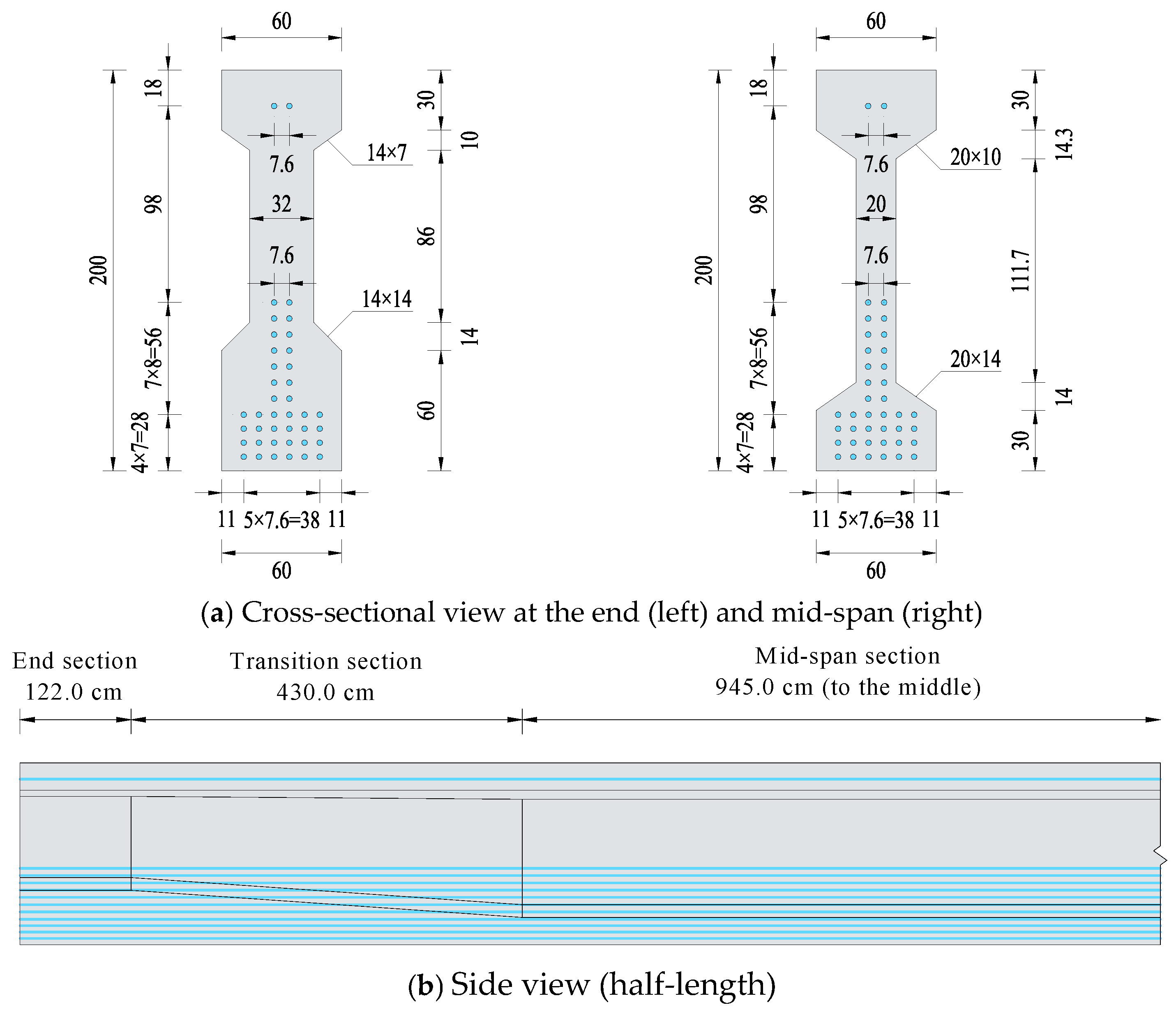
3.1. Details of Tested Girder
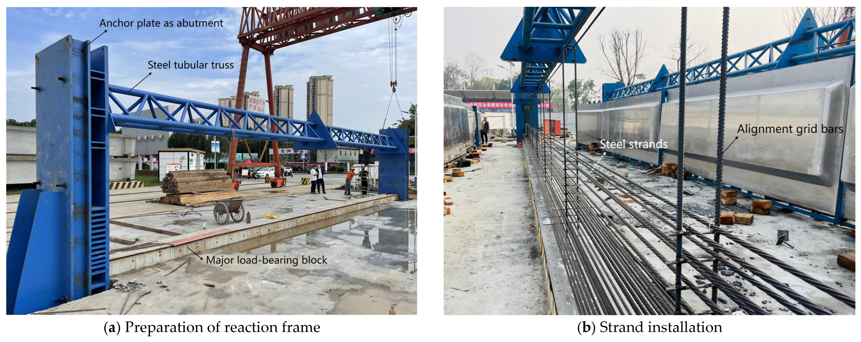
3.2. Girder Preparation
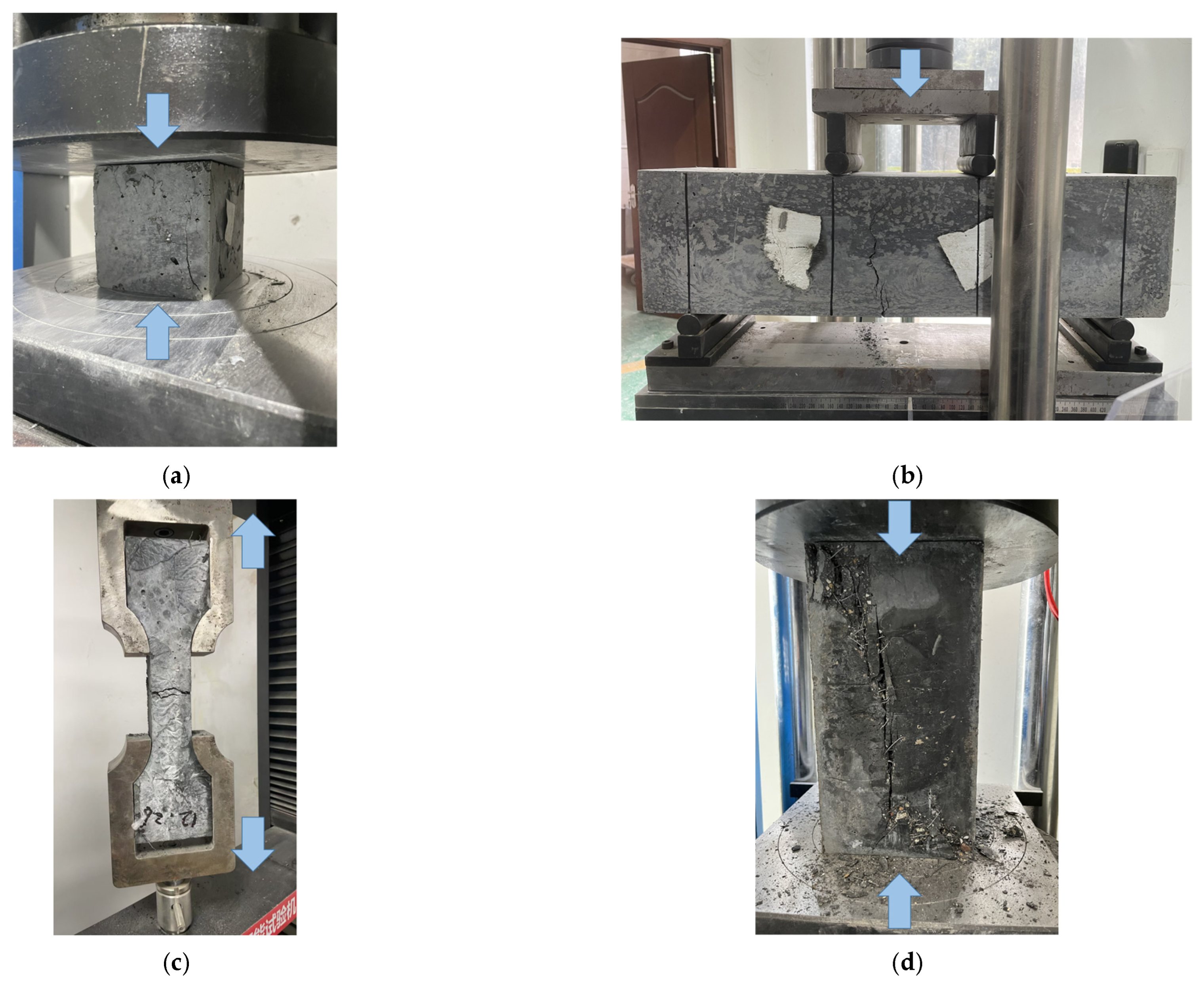
3.3. Material Properties
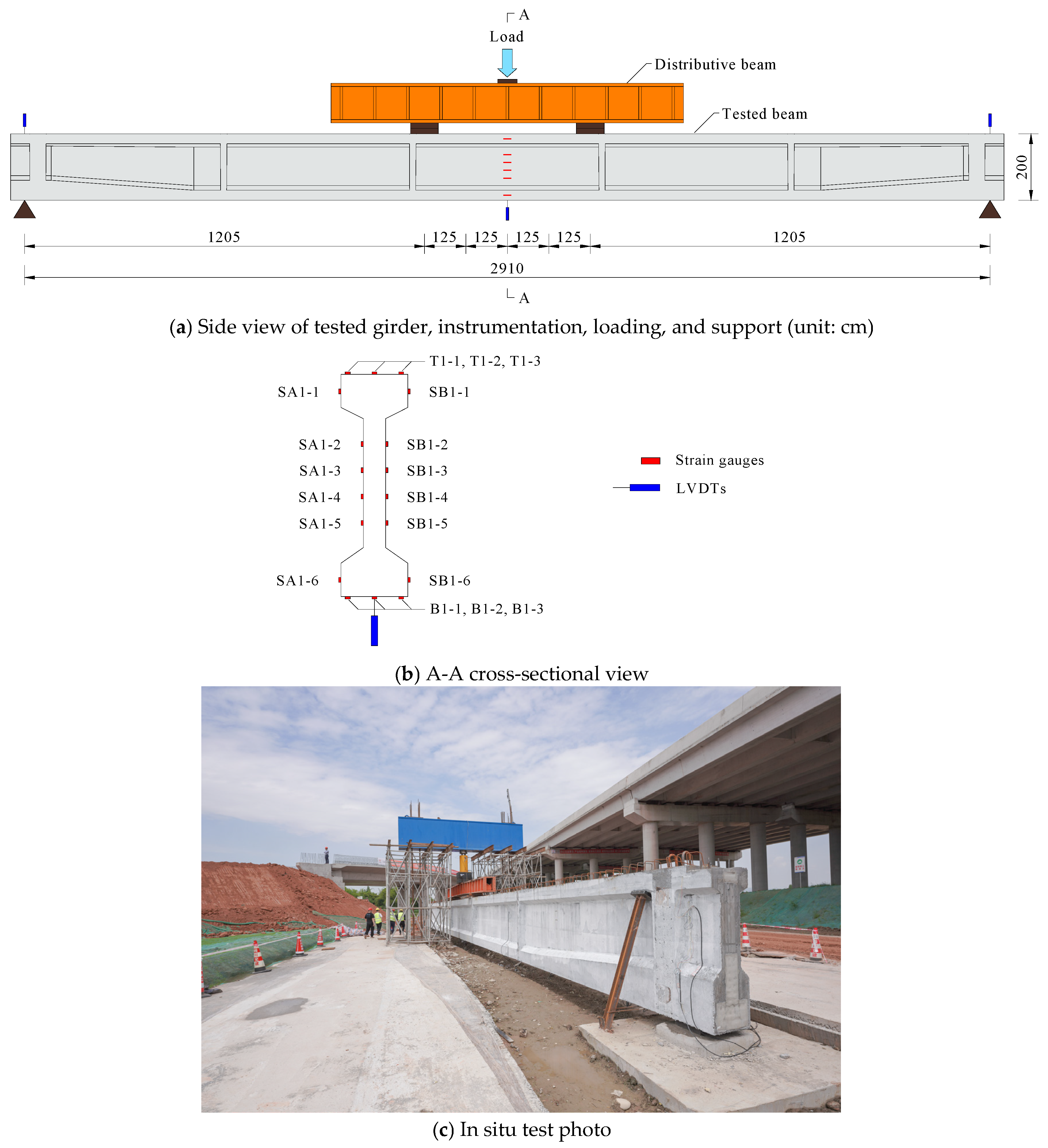
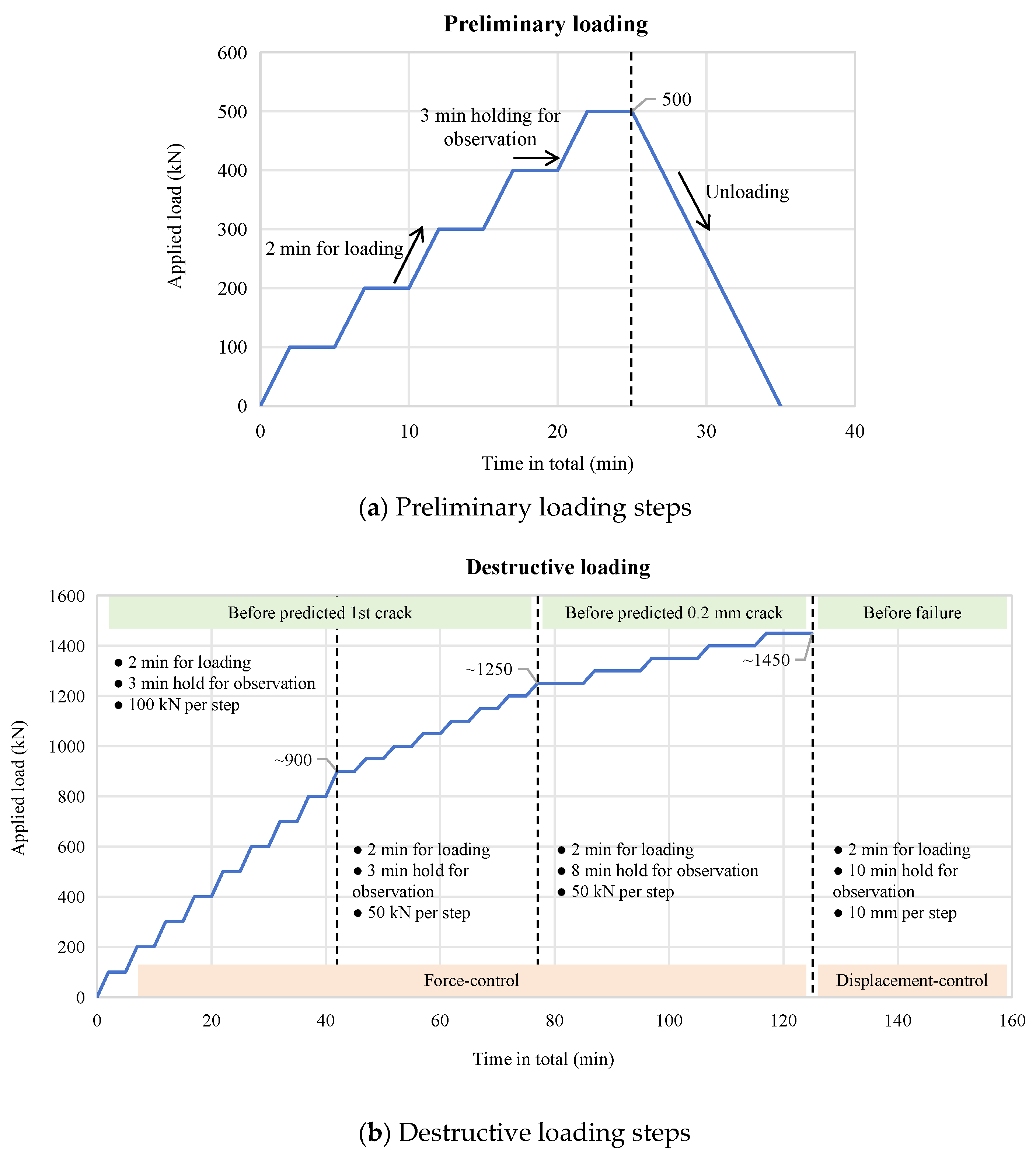
3.4. Test Setup and Load Protocol
4. Experimental Results
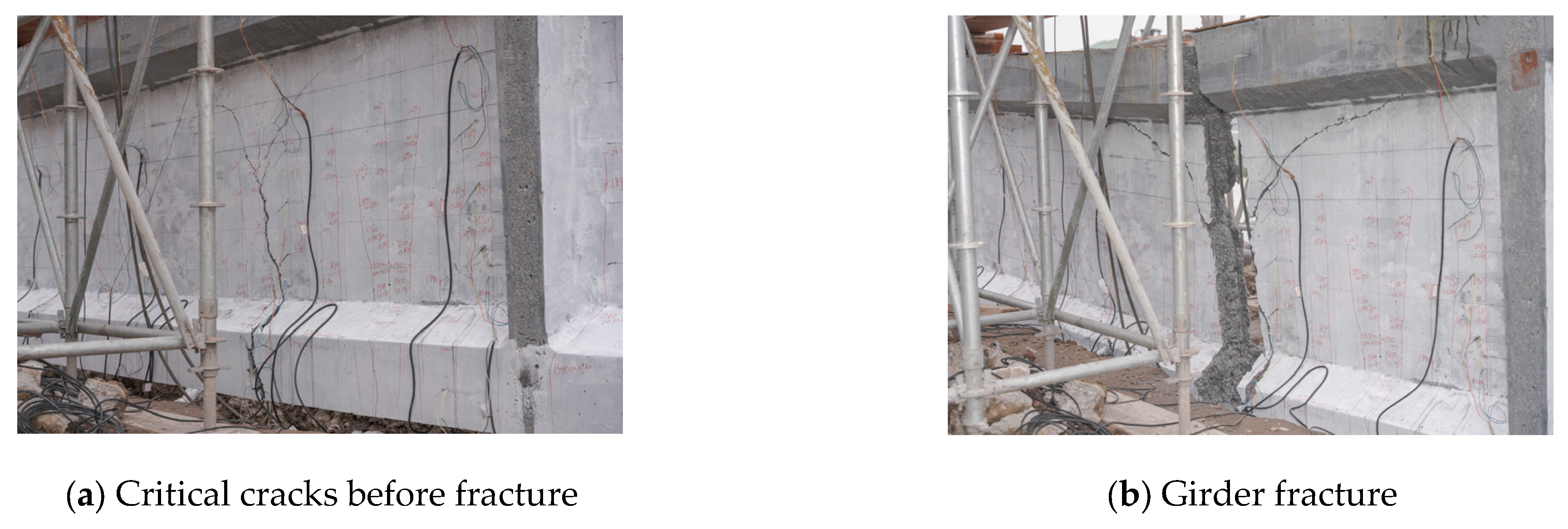
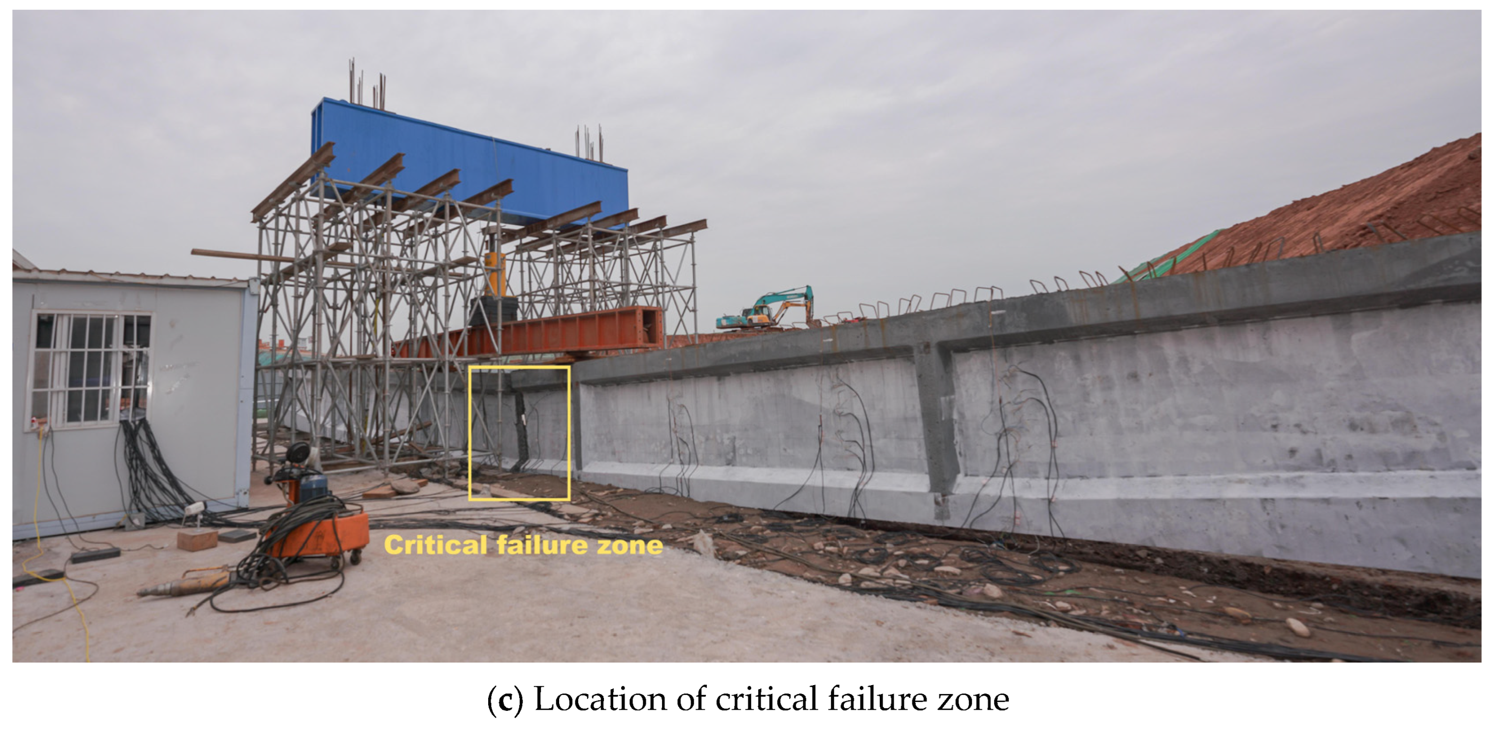
4.1. Failure Mode
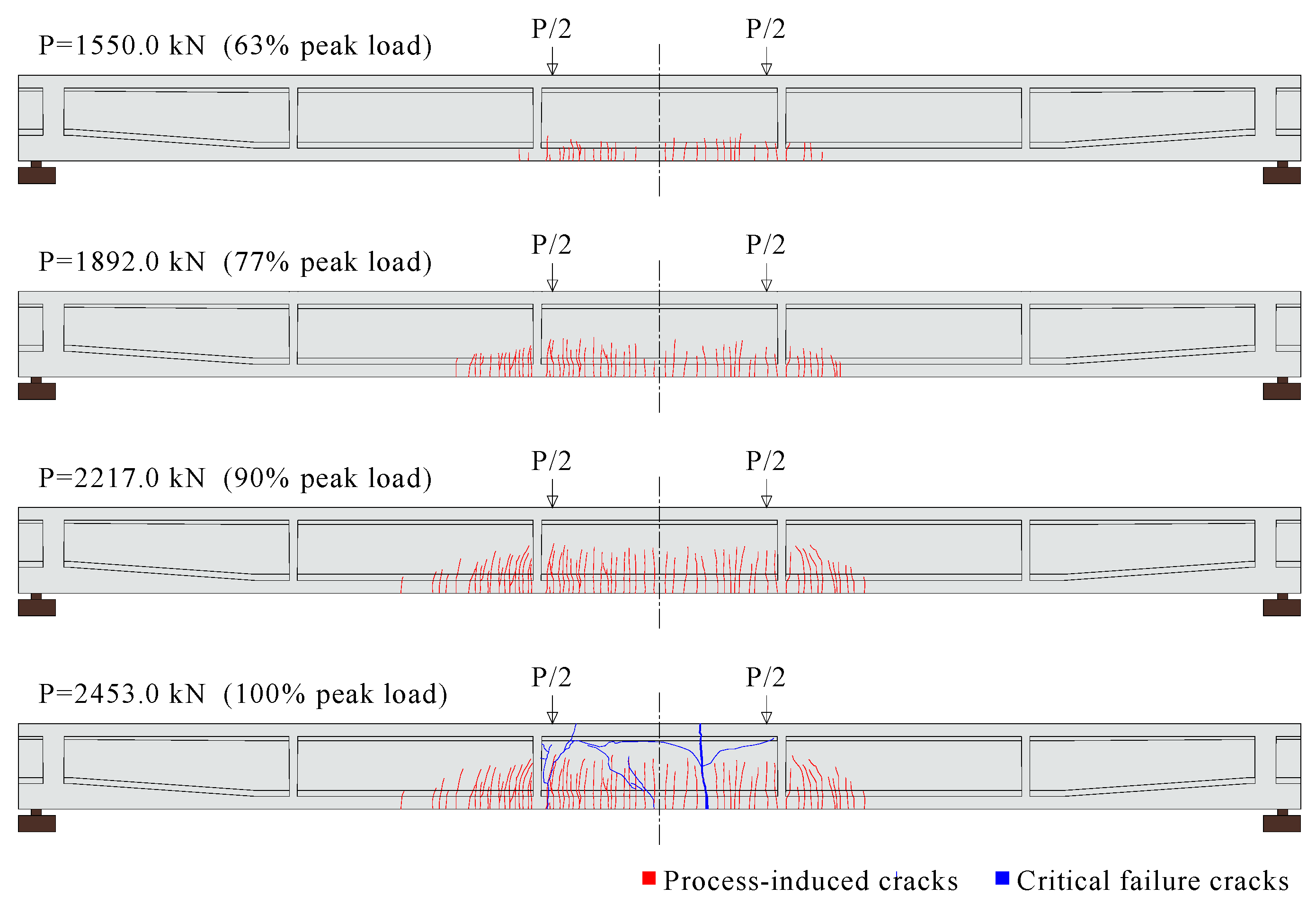
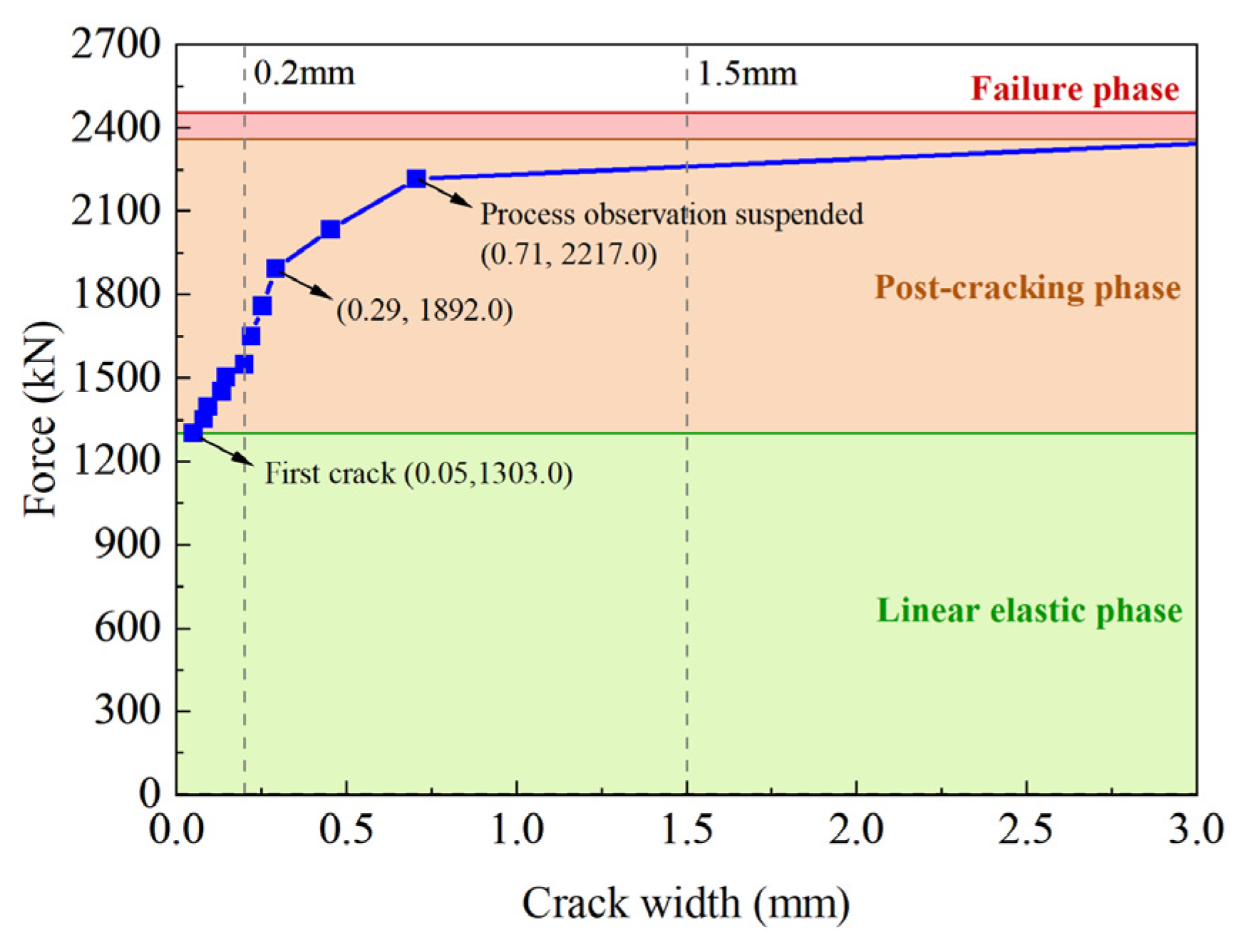
4.2. Crack Analysis
4.3. Load–Deflection Curves
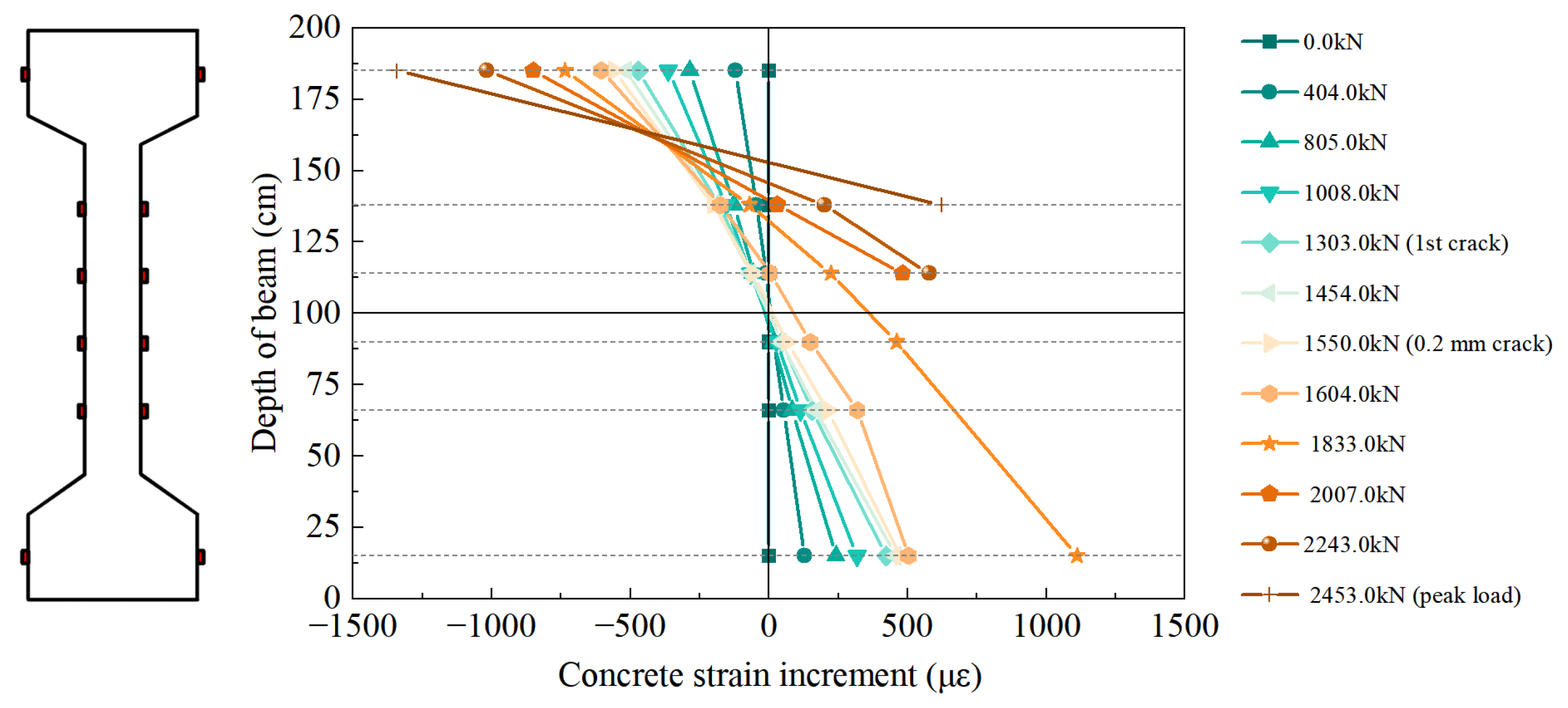
4.4. Plane Section Assumption
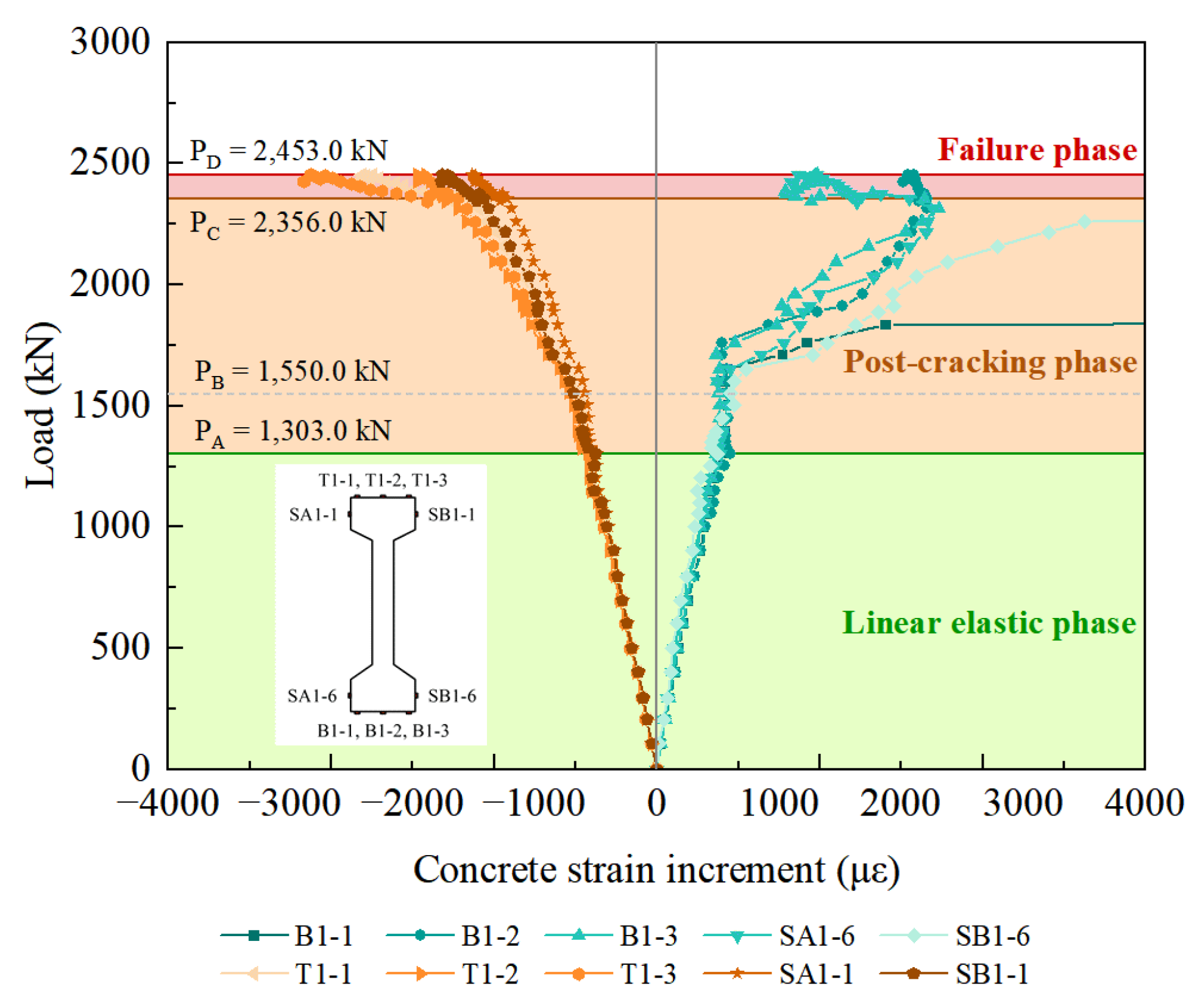
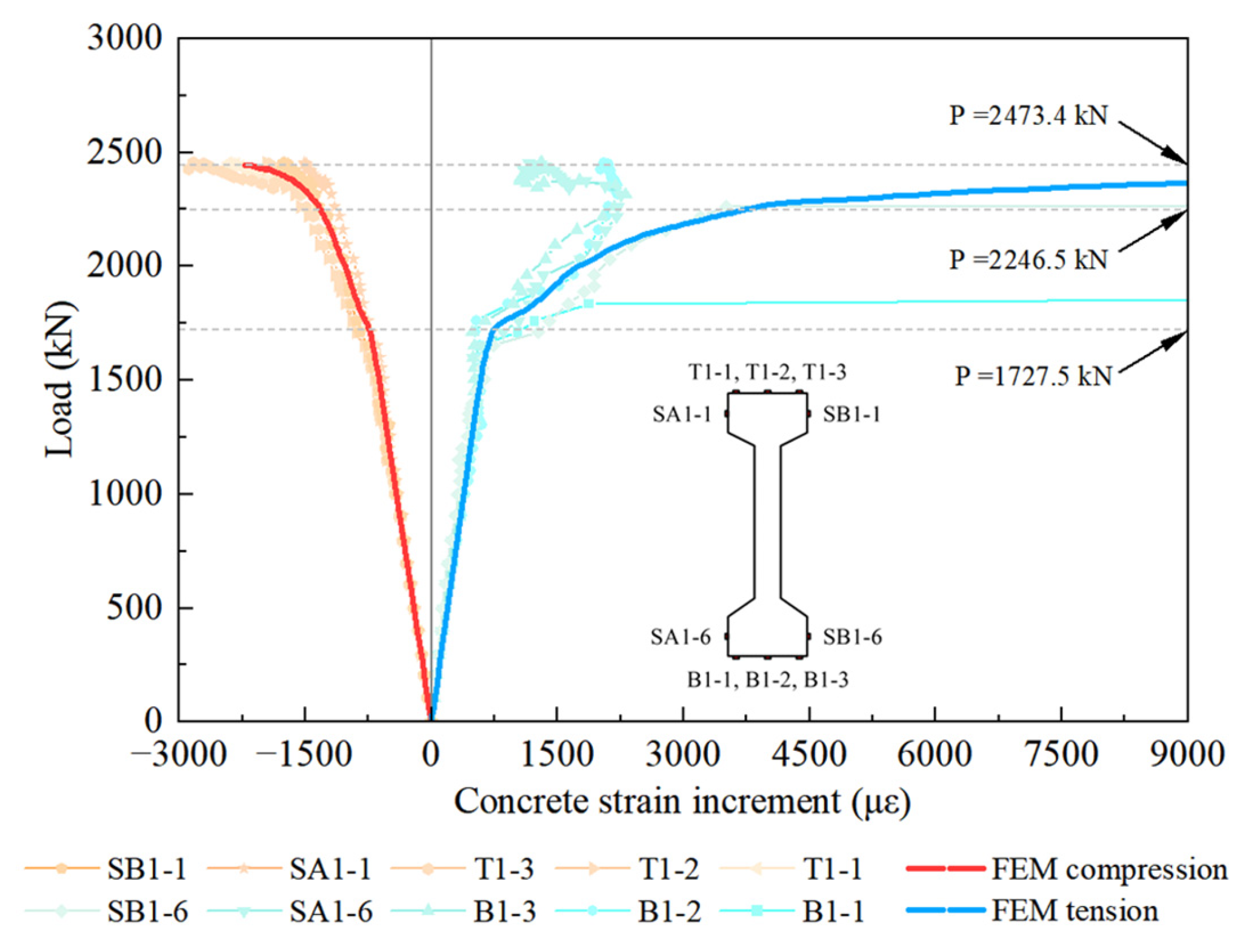
4.5. Concrete Strain
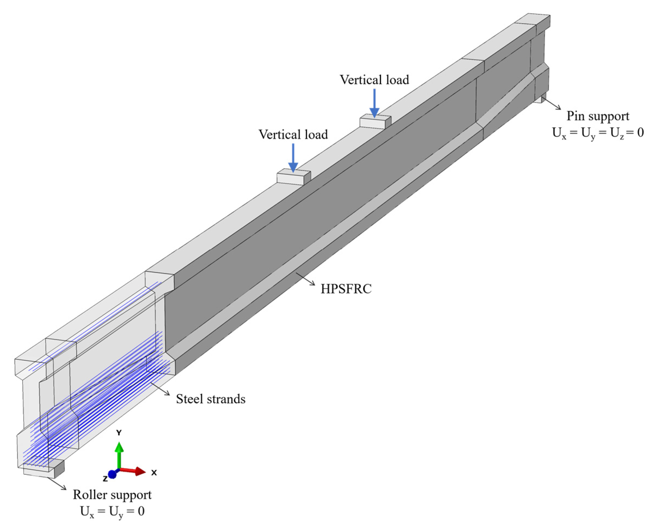
5. Finite Element Analysis
5.1. General
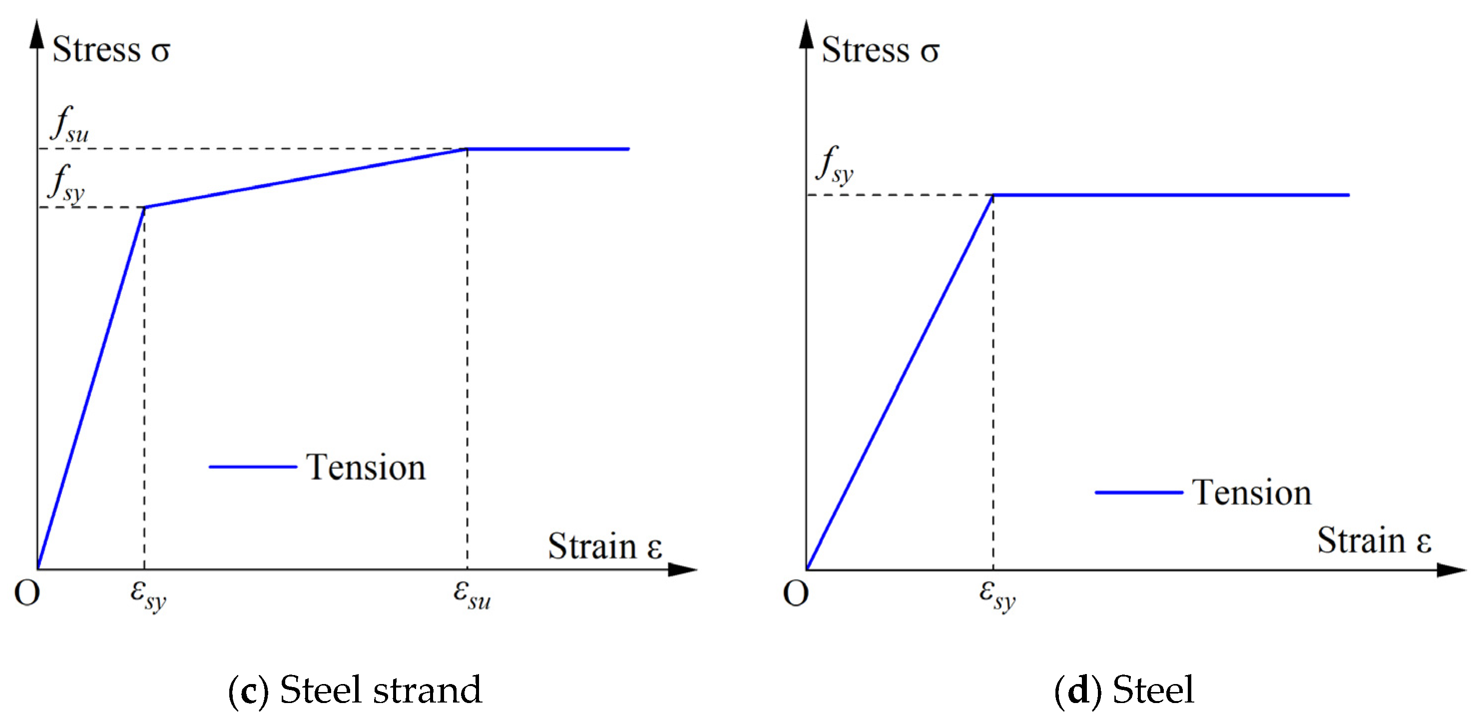
5.2. Material Constitutive Models
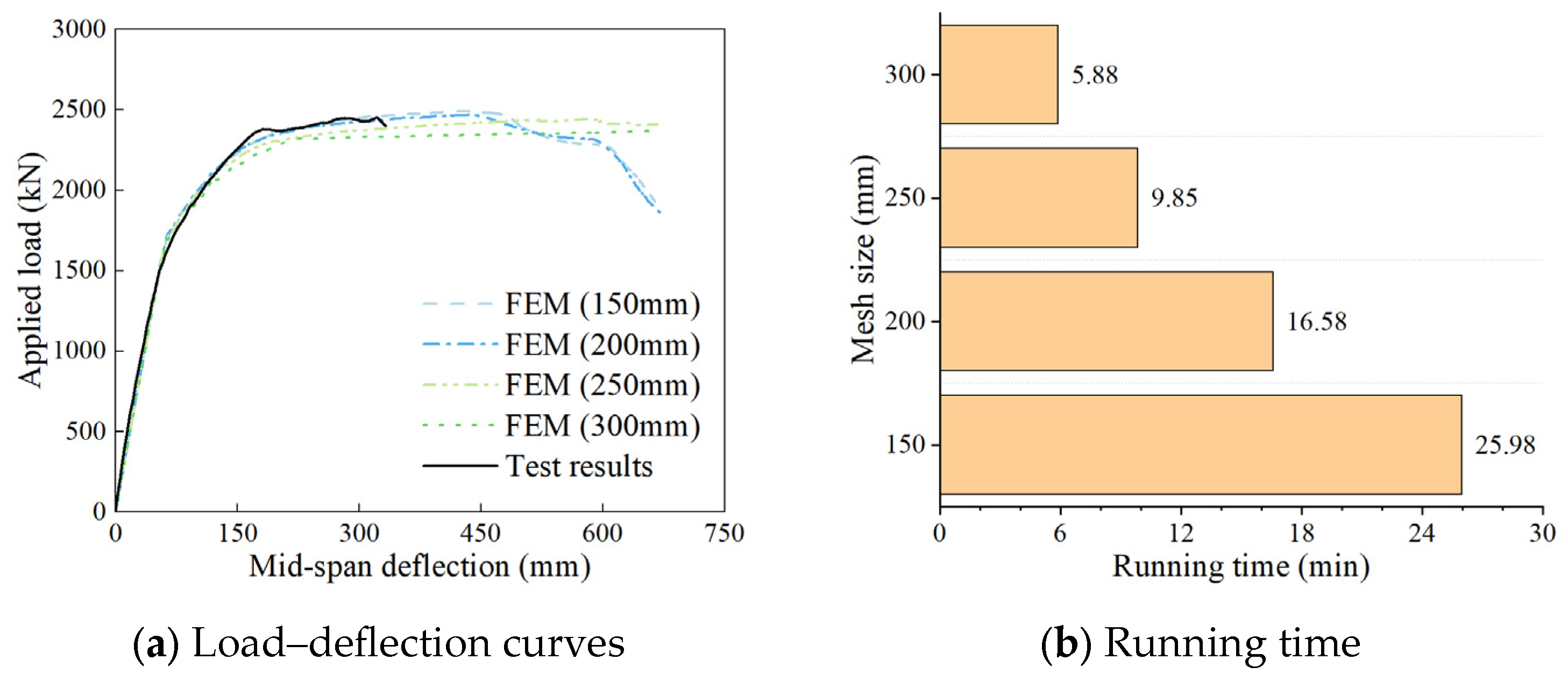
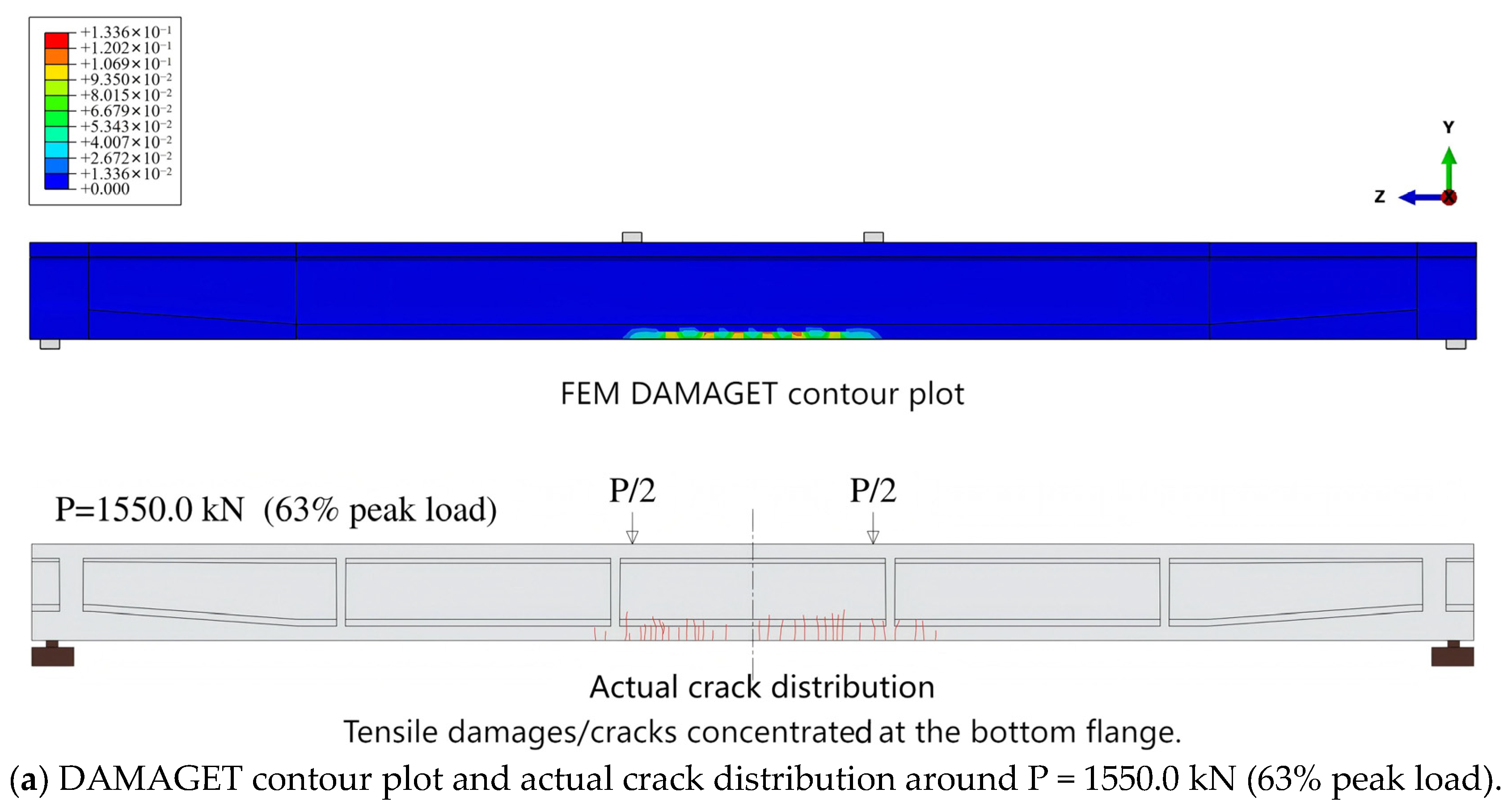
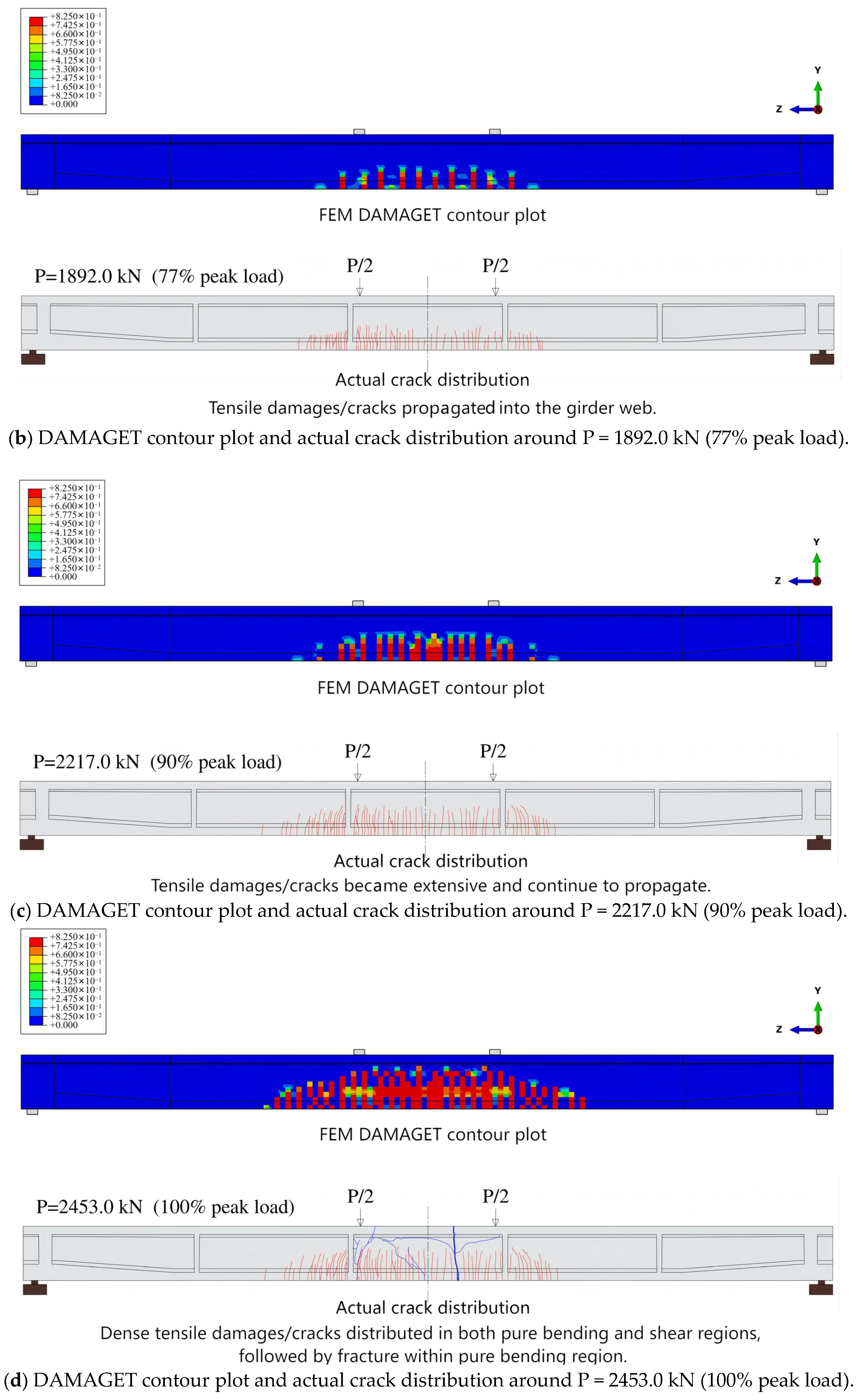
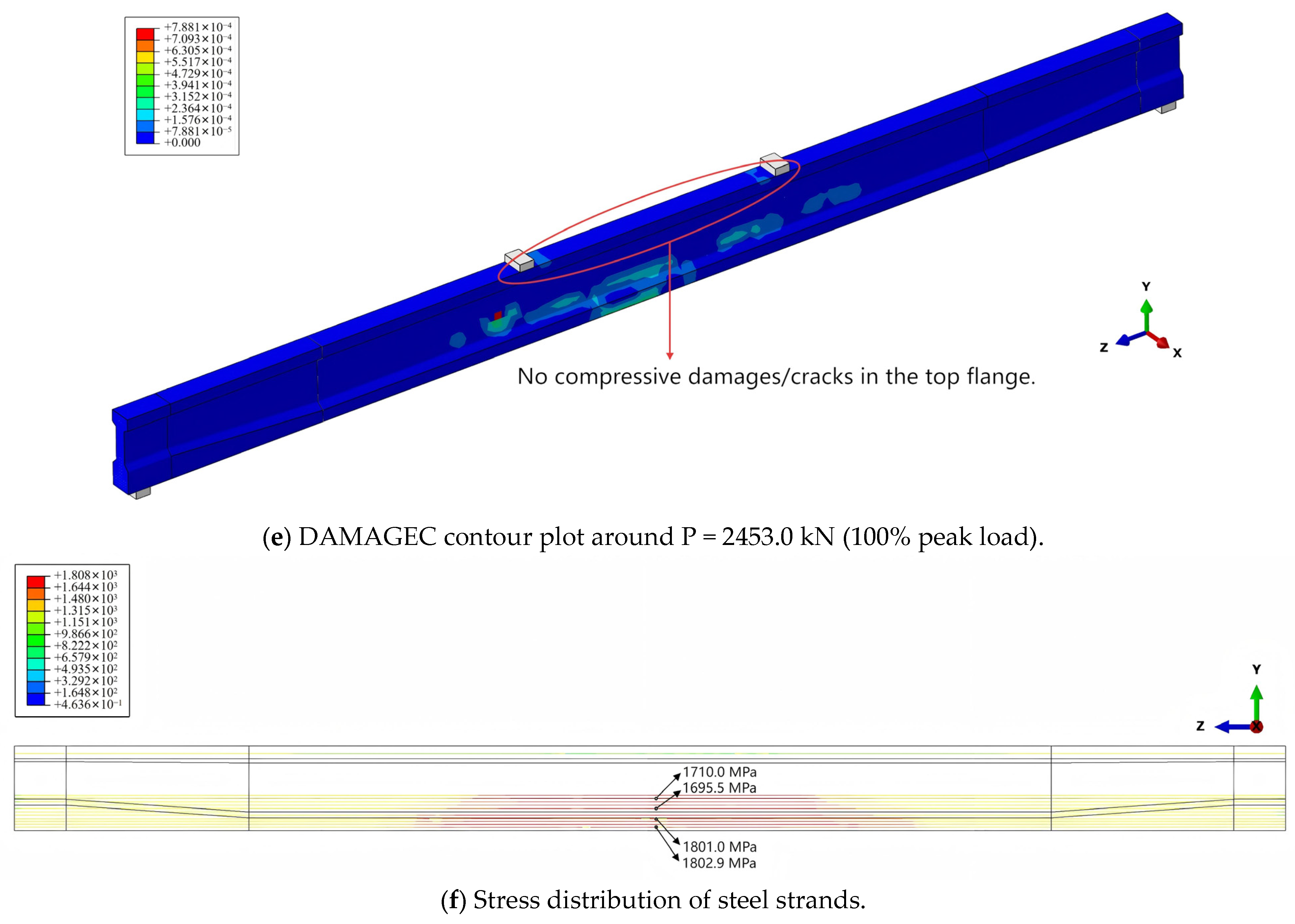
5.3. Verification of Results
5.4. Parametric Study
6. Discussions
7. Conclusions
Author Contributions
Funding
Data Availability Statement
Conflicts of Interest
Abbreviations
| NSC | Normal-strength concrete |
| HPC | High-performance concrete |
| SCMs | Supplementary cementitious materials |
| SFRC | Steel-fiber-reinforced concrete |
| HPSFRC | High-performance steel-fiber-reinforced concrete |
| UHPC | Ultra- high-performance concrete |
| FEM | Finite element model |
| CDP | Concrete damage plasticity |
References
- Leung, C.K.Y. Concrete as a Building Material. Encyclopedia of Materials: Science and Technology; Elsevier: Amsterdam, The Netherlands, 2001; pp. 1471–1479. [Google Scholar] [CrossRef]
- Zheng, Y.; Lv, X.; Hu, S.; Zhuo, J.; Wan, C.; Liu, J. Mechanical properties and durability of steel fiber reinforced concrete: A review. J. Build. Eng. 2024, 82, 108025. [Google Scholar] [CrossRef]
- Naaman, A.E.; Reinhardt, H.W. Proposed classification of HPFRC composites based on their tensile response. Mater. Struct./Mater. Constr. 2006, 39, 547–555. [Google Scholar] [CrossRef]
- Mufti, A.A.; Leslie, G.J.; Baidar, B.; Leon, D.W. Experimental investigation of fibre-reinforced concrete deck slabs without internal steel reinforcement. Can. J. Civ. Eng. 1993, 20, 398–406. [Google Scholar] [CrossRef]
- Kwak, Y.; Eberhard, O.M.; Kim, W.; Kim, J. Shear strength of steel fiber-reinforced concrete beams without stirrups. ACI Struct. J. 2002, 99, 530–538. [Google Scholar] [CrossRef]
- Padmarajaiah, S.K.; Ramaswamy, A. Flexural strength predictions of steel fiber reinforced high-strength concrete in fully/partially prestressed beam specimens. Cem. Concr. Compos. 2004, 26, 275–290. [Google Scholar] [CrossRef]
- Dhonde, H.B.; Mo, Y.L.; Hsu, T.T.C. Fiber Reinforcement in Prestressed Concrete Beams; University of Houston: Houston, TX, USA, 2005. [Google Scholar]
- Azmee, N.M.; Shafiq, N. Ultra-high performance concrete: From fundamental to applications. Case Stud. Constr. Mater. 2018, 9, e00197. [Google Scholar] [CrossRef]
- Xue, J.; Briseghella, B.; Huang, F.; Nuti, C.; Tabatabai, H.; Chen, B. Review of ultra-high performance concrete and its application in bridge engineering. Constr. Build. Mater. 2002, 260, 119844. [Google Scholar] [CrossRef]
- Zhou, M.; Lu, W.; Song, J.; Lee, G.C. Application of Ultra-High Performance Concrete in bridge engineering. Constr. Build. Mater. 2018, 186, 1256–1267. [Google Scholar] [CrossRef]
- Blais, P.Y.; Couture, M. precast, prestressed pedestrian bridge-world’s first Reactive Powder Concrete structure. PCI J. 1999, 44, 60–71. [Google Scholar] [CrossRef]
- Fehling, E.; Bunje, K.; Schmidt, M.; Tue, N.V.; Schreiber, W.; Humburg, E. Design of first hybrid UHPC-steel bridge across River Fulda in Kassel, Germany. In Proceedings of the IABSE Symposium, Weimar 2007: Improving Infrastructure Worldwide, Weimar, Germany, 19–21 September 2007. [Google Scholar] [CrossRef]
- Chen, B.; An, M.; Huang, Q.; Wu, H.; Huang, W.; Zhao, Q. Application of Ultra-High Performance Concrete in Bridge Engineering in China. In Proceedings of the First International Interactive Symposium on UHPC 2016, Iowa State University, Des Moines, IA, USA, 27–30 October 2016. [Google Scholar] [CrossRef]
- Kasuga, A. Effects of butterfly web design on bridge construction. Struct. Concr. 2017, 18, 128–142. [Google Scholar] [CrossRef]
- Fan, D.; Tian, W.; Feng, D.; Cheng, J.; Yang, R.; Zhang, K. Development and Applications of Ultra-high Performance Concrete in Bridge Engineering. IOP Conf. Ser. Earth Environ. Sci. 2018, 189, 022038. [Google Scholar] [CrossRef]
- Graybeal, B.; Brühwiler, E.; Kim, B.-S.; Toutlemonde, F.; Voo, Y.L.; Zaghi, A. International Perspective on UHPC in Bridge Engineering. J. Bridge Eng. 2020, 25. [Google Scholar] [CrossRef]
- Su, J.Z.; Ma, X.L.; Chen, B.C.; Sennah, K. Full-scale bending test and parametric study on a 30-m span prestressed ultra-high performance concrete box girder. Adv. Struct. Eng. 2020, 23, 1276–1289. [Google Scholar] [CrossRef]
- Graybeal, B.A. Flexural Behavior of an Ultrahigh-Performance Concrete I-Girder. J. Bridge Eng. 2008, 13. [Google Scholar] [CrossRef]
- Tu, W.; Cheng, Q.; Zhang, L.; Li, P.; Jiang, H.; Tian, Y.; Fang, J. Shear performance of 25 m full-scale prestressed UHPC-NC composite I-beam without stirrups. Case Stud. Constr. Mater. 2024, 21, e03942. [Google Scholar] [CrossRef]
- Folino, P.; Ripani, M.; Xargay, H.; Rocca, N. Comprehensive analysis of Fiber Reinforced Concrete beams with conventional reinforcement. Eng. Struct. 2020, 202, 109862. [Google Scholar] [CrossRef]
- Wu, T.; Sun, Y.; Liu, X.; Cao, Y. Comparative study of the flexural behavior of steel fiber-reinforced lightweight aggregate concrete beams reinforced and prestressed with CFRP tendons. Eng. Struct. 2021, 233, 1119021. [Google Scholar] [CrossRef]
- Li, C.; Zhu, H.; Niu, G.; Cheng, S.; Gu, Z.; Yang, L. Flexural behavior and a new model for flexural design of concrete beams hybridly reinforced by continuous FRP bars and discrete steel fibers. Structures 2022, 38, 949–960. [Google Scholar] [CrossRef]
- Qasim, M.; Lee, C.K.; Zhang, Y.X. Flexural strengthening of reinforced concrete beams using hybrid fibre reinforced engineered cementitious composite. Eng. Struct. 2023, 284, 115992. [Google Scholar] [CrossRef]
- JTG D60-2015; General Code for Desigh of Highway Bridges and Culverts. China Communications Press: Beijing, China, 2015.
- JTG 3362-2018; Specifications for Design of Highway Reinforced Concrete and Prestressed Concrete Bridges and Culverts. China Communications Press: Beijing, China, 2018.
- GB/T 31387-2015; Reactive Powder Concrete. Standardization Administration of China: Beijing, China, 2015.
- JG/T 472-2015; Steel Fiber Reinforced Concrete. Ministry of Housing and Urban-Rural Development of China: Beijing, China, 2015.
- GB/T 50081-2019; Standard for Test Methods of Concrete Physical and Mechanical Properties. Ministry of Housing and Urban-Rural Development of China: Beijing, China, 2019.
- JT/T 329-2010; Prestressing Strand Anchorage, Grip and Coupler for Highway Bridge. Ministry of Transport of China: Beijing, China, 2010.
- GB 50010-2010(2015); Code for Design of Concrete Structures. China Architecture & Building Press: Beijing, China, 2015.
- GB 50204-2015; Code for Acceptance of Constructional Quality of Concrete Structures. China Architecture & Building Press: Beijing, China, 2015.
- Kim, D.-j.; Naaman, A.E.; El-Tawil, S. Comparative flexural behavior of four fiber reinforced cementitious composites. Cem. Concr. Compos. 2008, 30, 917–928. [Google Scholar] [CrossRef]
- Contento, A.; Aloisio, A.; Xue, J.; He, J.; Briseghella, B. Ultra-high performance concrete beam-to-beam connections in continuous bridges: Experimental full-scale tests, FE analyses and design. Eng. Struct. 2024, 316, 118594. [Google Scholar] [CrossRef]
- Ezeldin, A.S.; Balaguru, P.N. Normal-and High-Strength Fiber-Reinforced Concrete under Compression. J. Mater. Civ. Eng. 1992, 4, 415–429. [Google Scholar] [CrossRef]
- Nataraja, M.C.; Dhang, N.; Gupta, A.P. Stress–strain curves for steel-fiber reinforced concrete under compression. Cem. Concr. Compos. 1999, 21, 383–390. [Google Scholar] [CrossRef]
- Lu, X.L.; Zhang, Y.; Nian, X.C. Stress-strain behavior for high-strength steel fiber reinforced concrete under monotonic and repeated compressive loading. J. Build Struct. 2017, 38, 43–135. [Google Scholar]
- Lok, T.-S.; Pei, J.-S. Flexural Behavior of Steel Fiber Reinforced Concrete. J. Mater. Civ. Eng. 1998, 10, 86–97. [Google Scholar] [CrossRef]
- Yang, M.; Huang, C.; Wang, J. Characteristics of stress-strain curve of high strength steel fiber reinforced concrete under uniaxial tension. J. Wuhan Univ. Technol. Mater. Sci. Ed. 2006, 21, 132–137. [Google Scholar] [CrossRef]
- Muhammad, F.; Harun, M.; Ahmed, A.; Kabir, N.; Khalid, H.R.; Hanif, A. Influence of bonded mortar on recycled aggregate concrete properties: A review. Constr. Build. Mater. 2024, 432, 136564. [Google Scholar] [CrossRef]
- de Assis, H.J.B.; da Silva Bezerra, A.C.; de Paula, J.N.; Moravia, W.G. Utilization of recycled synthetic fibers in concrete with a focus on structural properties enhancement: A critical literature review. Discov. Mater. 2024, 4, 77. [Google Scholar] [CrossRef]
- Ahmad, F.; Qureshi, M.I.; Rawat, S.; Alkharisi, M.K.; Alturki, M. E-waste in concrete construction: Recycling, applications, and impact on mechanical, durability, and thermal properties—A review. Innov. Infrastruct. Solut. 2025, 10, 246. [Google Scholar] [CrossRef]


| Researcher | Material | Span Length (m) | Shape of Section | Conventional Reinforcement |
|---|---|---|---|---|
| Kwak et al. [5] | SFRC | 2.40 | Rectangle | Two D16 longitudinal reinforcement, and three D10 stirrups at each end |
| Padmarajaiah & Ramaswamy [6] | HPSFRC | 2.20 | Rectangle | Reduced shear reinforcement and only in shear span |
| Dhonde et al. [7] | HPSFRC | 7.62 | I-shape | Reduced shear reinforcement with 40 cm spacing |
| Su et al. [17] | UHPFRC | 30.00 | Box | 46% reduced prestress strands, 8% reduced reinforcement |
| Graybeal [18] | UHPFRC | 23.90 | I-shape | No mild steel reinforcement |
| Tu et al. [19] | UHPFRC + NSC | 25.00 | UHPFRC-NSC composite I-shape | No stirrups in girder |
| Folino et al. [20] | SFRC | 2.10 | Rectangle | From full reinforcement to no reinforcing bars |
| Wu et al. [21] | SFRC | 4.20 | Rectangle | Reduced shear reinforcement |
| Li et al. [22] | HPSFRC | 2.10 | Rectangle | Reduced shear reinforcement and only in shear span |
| Qasim et al. [23] | Hybrid fiber-reinforced HPC | 3.50 | Rectangle | Reduced shear reinforcement |
| Load Condition | |||
|---|---|---|---|
| prestressing | 14.9 | - | - |
| service load combinations | - | 10.5 | 3.7 |
| Cement | SCMs | Sand | Coarse Aggregate | Water-to-Binder Ratio | Superplasticizer | Steel Fiber |
|---|---|---|---|---|---|---|
| 1 | 0.15 | 0.98 | 1.2 | 0.2 | 0.02 | 1.9% |
| Type of Fiber | Diameter (mm) | Length (mm) | Tensile Strength (MPa) | Elastic Modulus (GPa) | Image |
|---|---|---|---|---|---|
| Hooked-end steel fiber | 0.6~0.9 | 30~35 | ≥600 | 200 |  |
| Concrete Type | Cubic Compressive Strength (MPa) | Flexural Tensile Strength (MPa) | Direct Tensile Strength (MPa) | Elastic Modulus (GPa) |
|---|---|---|---|---|
| HPSFRC | 106.3 | 12.0 | 8.7 | 40.7 |
| Researcher | Girder Type | ||
|---|---|---|---|
| Graybeal [18] | 23.9 m UHPFRC I-shaped girder with no steel reinforcement | 0.41 | 1/51 |
| Tu et al. [19] | 25.0 m UHPFRC-NSC composite I-shaped girder with no stirrups | 0.43 | 1/92 |
| This study | 30.0 m HPSFRC I-shaped girder with no steel reinforcement | 0.53 | 1/86 |
Disclaimer/Publisher’s Note: The statements, opinions and data contained in all publications are solely those of the individual author(s) and contributor(s) and not of MDPI and/or the editor(s). MDPI and/or the editor(s) disclaim responsibility for any injury to people or property resulting from any ideas, methods, instructions or products referred to in the content. |
© 2025 by the authors. Licensee MDPI, Basel, Switzerland. This article is an open access article distributed under the terms and conditions of the Creative Commons Attribution (CC BY) license (https://creativecommons.org/licenses/by/4.0/).
Share and Cite
Kang, L.; Zou, H.; Mu, T.; Pei, F.; Bai, H. Flexural Behavior of Pre-Tensioned Precast High-Performance Steel-Fiber-Reinforced Concrete Girder Without Conventional Reinforcement: Full-Scale Test and FE Modeling. Buildings 2025, 15, 2308. https://doi.org/10.3390/buildings15132308
Kang L, Zou H, Mu T, Pei F, Bai H. Flexural Behavior of Pre-Tensioned Precast High-Performance Steel-Fiber-Reinforced Concrete Girder Without Conventional Reinforcement: Full-Scale Test and FE Modeling. Buildings. 2025; 15(13):2308. https://doi.org/10.3390/buildings15132308
Chicago/Turabian StyleKang, Ling, Haiyun Zou, Tingmin Mu, Feifei Pei, and Haoyuan Bai. 2025. "Flexural Behavior of Pre-Tensioned Precast High-Performance Steel-Fiber-Reinforced Concrete Girder Without Conventional Reinforcement: Full-Scale Test and FE Modeling" Buildings 15, no. 13: 2308. https://doi.org/10.3390/buildings15132308
APA StyleKang, L., Zou, H., Mu, T., Pei, F., & Bai, H. (2025). Flexural Behavior of Pre-Tensioned Precast High-Performance Steel-Fiber-Reinforced Concrete Girder Without Conventional Reinforcement: Full-Scale Test and FE Modeling. Buildings, 15(13), 2308. https://doi.org/10.3390/buildings15132308