Article

Energy Dissipation Device Design for Irregular Structures Based on Yield Mechanism

1
School of Civil Engineering, Shandong Jianzhu University, 1000 Fengming Rd., Jinan 250101, China
2
Key Laboratory of Building Structural Retrofitting and Underground Space Engineering, Ministry of Education, Shandong Jianzhu University, Jinan 250101, China
3
Jiaodong Company, The Fourth Construction Co., Ltd. of China Construction Eighth Engineering Bureau, Yantai 264001, China
4
Shandong Provincial Architecture Design & Research Institute Company Limited, Jinan 250001, China
5
College of Civil Engineering, Tongji University, 1239 Siping Rd., Shanghai 200092, China
*
Author to whom correspondence should be addressed.
Buildings 2025, 15(13), 2305; https://doi.org/10.3390/buildings15132305
Submission received: 23 May 2025 / Revised: 14 June 2025 / Accepted: 22 June 2025 / Published: 30 June 2025
(This article belongs to the Section Building Structures)

Abstract

The seismic performance of irregular structures can be enhanced by installing energy dissipation devices. The location and specification of those devices are crucial for the design of the structure with an energy dissipation device. In this paper, an idea based on the structural yield mechanism is proposed. Specifically, the pushover method was employed to analyze the yield sequence of structural members, thereby determining weak components that dictate the location of these devices. Additionally, the story drift ratios were taken as the control target to determine the performance parameters of the devices. This concept has been applied to the design of an energy dissipation device for a medical building. The results demonstrated that by using a design method based on the yield mechanism, the location of the damper was rapidly determined to ensure that the yield mechanism of the irregular structure met expectations. To control the story drift ratios, the parameters of the damper were selected, and the center of damping strength and the center of stiffness were made symmetrical about the center of mass, which could enable the irregular structure to have a better damping effect. After setting the energy dissipation devices according to this method, the structural torsional displacement ratio was reduced from 1.32 to 1.04, and the displacement angle between layers was reduced from 0.01 to 0.0048.

1. Introduction

Architectural design often results in irregular and asymmetrical spaces and forms that accommodate diverse functional and aesthetic requirements. However, such irregularities in building shapes and structural systems present significant challenges to seismic resistance, substantially increasing both construction complexity and costs. Research and post-earthquake damage assessments consistently show that irregular structures experience significantly higher seismic responses compared to their regular counterparts. Mazza et al. [1] have demonstrated through research that buildings with fixed foundations and base-isolated structures alike are subject to comparably significant seismic responses. This increased response is primarily due to pronounced torsional effects under seismic forces, which intensify with the degree of structural irregularity.
Extensive research has been conducted on the seismic behavior of irregular structures. In 1989, Reem et al. [2] analyzed the vertex displacement, bottom shear force, and overturning moment at the base of an irregular structure under seismic action. They pointed out that the torsional effect would deteriorate the component’s performance, leading to structural damage or even collapse. The experimental and theoretical analysis conducted by Bertero [3] in 1996 demonstrated that the insufficient deformation capacity and energy dissipation capacity of structures were the primary causes of their collapse under large earthquakes. In 1997, Qian et al. [4] compiled design samples of common irregular structures in the United States from the 1980s and concluded that seismic design principles applicable to irregular buildings were suitable for use as a reference for engineering design. In 2005, Wei et al. [5] discovered that the position of the lateral force-resisting members of a structure had a significant influence on torsion and proposed that the torsional effect should be minimized in the design of irregular structures. Lin et al. [6] examined the behavior of an irregular structure with large openings. The investigation disclosed significant torsional effects and fluctuations in lateral resistance capacity, with vulnerable areas identified at split-level corners and structural discontinuities.
Wang et al. [7] examined recent advancements in research on the inelastic torsion of planar irregular building systems under seismic forces. They proposed that future studies should investigate not only structural torsion but also the effect of torsional ground motion on buildings. Zhang et al. [8] investigated the torsional properties of a multilayer frame structure with an L-shaped plane. They also examined how bidirectional eccentricity affects the structure’s torsional effect. In the research conducted by Feng et al. [9], the post-frame shear wall structure of a super high-rise residential building with a small waist and butterfly shape was found to meet seismic performance requirements by employing strengthening methods during shape change.
Traditional seismic design consumes seismic energy through structural member deterioration, which is a form of direct resistance. The torsion impact of irregular structures is evident during seismic events, particularly infrequent ones, making it difficult to guarantee the safety of the structure through direct resistance. This issue can be addressed by designing energy dissipation devices, which involve adding energy dissipation devices to offer additional stiffness or damping to the structure, thereby indirectly reducing the seismic response of the primary structure. From the beginning of the twenty-first century, regulations and standards for the design of seismic energy dissipation devices have been introduced sequentially [10,11,12]. The mechanical model, performance characteristics of dampers, selection of structural systems, and seismic response analysis are outlined in the “Technical Specification for Seismic Energy Dissipation of Buildings (JGJ297-2013 [13])”. However, the damper layout plan and the design process for structures with energy dissipation devices remain unclear. In 2005, Liu et al. [14] employed the elastic–plastic time-history analysis method to investigate the seismic response of multilayer buckling-restrained brace (BRB)–steel frame structures, examining how BRB layout and the BRB/frame lateral stiffness ratio impact seismic performance. Furthermore, building on the seismic principles of the standard response spectrum and target displacement, they simplified the design approach for the BRB–steel frame structure. Cheng et al. [15] studied the seismic response of eccentric structures, including those with normal braces, unbounded braces (UBBs), and fluid viscous dampers. It has been demonstrated that energy dissipation devices can significantly reduce structural responses. Men et al. [16] suggested a torsion angle capacity spectrum approach for performance-based seismic evaluation of irregular plane frame constructions. Torsion angle demand curves were established by considering inter-story ratio limit values for performance levels under different earthquake hazard levels. The structural torsion angle and capacity curves were then obtained using existing finite element analysis software. For the design of damping structures, the Japan Seismic Isolation Association’s “Handbook for Design and Construction of Passive Seismic Mitigation Structures” [17] suggests using the damping performance curves of single-degree-of-freedom systems. Fang et al. [18] conducted a comprehensive study on the torsional design of irregular structures in 2009, focusing on two key aspects: resistance to the torsional effect and its control. Their in-depth analysis of structural torsional effects and the factors influencing them led to the development of a set of quick determination techniques, including the structural period ratio, torsional displacement ratio, and torsional component ratio. The results indicate that while layer eccentricity significantly influences the structure’s torsional behavior, a more effective control strategy involves increasing the torsional displacement ratio and component ratio by adjusting layer eccentricity. Furthermore, proactive structural torsion management proves to be more advantageous than solely relying on the structure’s inherent capacity to endure torsional forces. Lin et al. [19] evaluated the sequence of damage and failure based on component significance, proposed a safety reserve expression for various components, and recommended a seismic optimization design method that incorporates these factors. In 2019, Naveen et al. [20] examined the seismic response of a regular nine-story frame by incorporating various forms of irregularities in both the horizontal and vertical planes. Their results indicated that the uneven stiffness significantly affected the seismic response of the irregular structure. In 2020, Liu et al. [21] investigated the impact of period ratio, displacement ratio, and eccentricity on torsional performance, proposing strategies to improve structural torsional performance during seismic events. Wang et al. [22] concentrated on the seismic response characteristics of eccentric base-isolated structures, analyzing the torsional response of irregular structures. The analytical model was developed utilizing the elastic–plastic time-history analysis method to evaluate the torsional response of the structure subjected to frequent, fortification, and rare seismic events, with the torsional displacement ratio serving as the response metric. The findings indicated that when the superstructure is eccentric, aligning the stiffness center of the isolation layer with the center of mass of the superstructure effectively reduces the torsional displacement ratio in the Y-direction. As a result, the torsional displacement ratio in the X-direction, as measured by inter-layer displacement, experiences a substantial increase. In 2022, Jin et al. [23] considered a high-rise office building design to regulate the torsional effect of the structure by thickening the perforated floor slab and strictly controlling the axial compression ratio of the vertical components in the reinforced area at the bottom.
Evaluating the damping effect by comparing the seismic responses of a structure before and after the installation of dampers is a commonly used method in China. However, the problem of optimal damper placement remains unresolved. In 2017, Du et al. [24] introduced a seismic mitigation design concept that was based on force transmission paths and established damper placement criteria. Nevertheless, the relative importance of each coefficient was calculated sequentially. This research presents an energy dissipation device design approach based on the structural yield mechanism. The pushover analysis method was used to determine the yield sequence of all structural components, thereby informing the formulation of a damper placement strategy. By implementing various types of dampers, the yield mechanism of the damped structure can be optimized for enhanced rationality and efficiency. Adjusting the type and parameters of dampers ensures that the damping strength center and the structural stiffness center are symmetrically aligned with the mass center, effectively reducing torsional effects and seismic response. This yield-mechanism-based design approach streamlines the design process for irregular structures.

2. Seismic Mitigation Design of Irregular Structures

The irregular geometry of the building’s design, coupled with the variation in lateral force resistance elements, is likely to create a misalignment between the center of mass and the center of stiffness within the structure. Additionally, this scenario can intensify the torsional response of the structural plane during seismic events. As a result of the applied plane torque, the lateral force components must handle extra shear forces; therefore, the distance of a component from the center of stiffness is directly linked to an increase in shear forces.
The key objective of energy dissipation device design is to ensure that the energy dissipation devices provide sufficient stiffness for the structure during frequent seismic occurrences (BRBs can provide sufficient stiffness and are typically used as such seismic reduction devices [25]), meeting the elastic limit criteria for story drift. During uncommon earthquakes, these devices act as the first line of defense, contributing additional damping to the main structure and dissipating the majority of seismic energy, enabling energy-dissipating units to exert a positive influence on the seismic capacity of both structural and non-structural components in buildings [26], reducing the main structure’s seismic response.
In the damper design method based on direct displacement [27], the seismic performance of the structure is first evaluated. The target displacement is determined according to the expected seismic response control objectives, and thereafter, different types of energy-dissipating devices are selected. The planar layout of the energy dissipation devices should be as uniform and symmetrical as feasible. In contrast, the layout of energy-dissipating devices should be continuous from top to bottom to provide uniformity in the structural plane and vertical stiffness distribution. Special attention should be paid to the fact that arranging energy dissipation devices on different levels may increase the lateral stiffness of individual floors. Specific parameters must be managed to avoid the creation of new weak layers.
The location and parameters of the energy dissipation device for the irregular structure should not only reduce the eccentricity between the structure’s mass center and the stiffness center but also make the damping strength center Cd and the stiffness center Cs as symmetrical with respect to the mass center Cm as possible, that is, ed = e (as shown in Figure 1), to mitigate the earthquake’s torsional effect.
The energy dissipation device should be placed on the floor with low lateral stiffness and large story drift, as well as a weak layer generated by abrupt vertical stiffness. Special attention should be given to those components that may collapse first as a result of a large earthquake response, such as the edge, the corner, the plane’s conversion site, and the edge location of the floor with large openings. In other words, the structure’s stiffness and damping distribution must be adjusted by arranging the energy dissipation device to make a more regular structure.

3. Energy Dissipation Device Design Idea Based on the Yield Mechanism of the Structure

3.1. Yield Mechanism of Irregular Structure

The order in which a structure’s components yield and the form of failure of that yielding are referred to as the yield mechanism. Under seismic action, reinforced concrete frame structures exhibit three types of yield mechanisms: First, the column hinge yield mechanism states that when subjected to horizontal seismic action, the ends of the frame columns yield earlier than the ends of the beams, resulting in plastic hinges. The frame columns with yielded upper and lower ends will lose their load-bearing capacity on this floor. Second, the beam hinge yield mechanism states that under horizontal seismic activity, plastic hinges form at the ends of the beams and the lower ends of the columns at ground level, while other sections remain elastic. This structure aligns with the design intent of “strong columns and weak beams”. Thirdly, the mixed yield mechanism of beams and columns indicates that, besides the plastic hinges at the beam ends, the upper ends of some frame columns yield while the lower ends remain stable. In structural design, it is essential to modify the strength relationships among different components to guarantee that the structure demonstrates the beam hinge yield mechanism during seismic events.
According to China’s codes, reinforced concrete frame structures are required to achieve a “strong-column–weak-beam” yield mechanism under seismic action. However, actual seismic damage investigations reveal that most reinforced concrete frame structures exhibit a “strong-beam–weak-column” failure mechanism, resulting in severe structural damage. Dong Lu et al. [28] studied the influence of cast-in situ floor slabs on the “strong-column–weak-beam” mechanism and discussed improvement measures for structures to achieve this mechanism under the influence of cast-in situ floor slabs. Starting from irregular structures, this paper examines the role of yield mechanisms in irregular structures for enhancing seismic resistance.
The seismic response of irregular structures is more complicated, and the mechanism of yielding is difficult to assess immediately. According to the seismic design code for buildings, irregular structures with visible weaknesses require a rare-earthquake-induced plastic study [29]. In this research, the pushover technique was employed to determine the yield mechanism of irregular structures using the concept of structural plastic deformation analysis.
Freeman et al. [30] introduced pushover as a method for assessing structural attributes. A lateral force or displacement increasing with height is applied to the structural model to induce lateral deformation until the control point reaches the target displacement or the structure overturns.
Pushover analysis provides a clear demonstration of the order of plastic hinges in structural components, allowing for an intuitive assessment of the structure’s yield mechanism. To identify the area where the energy dissipation device should be installed, the component yield order studied by the pushover method can be used to determine the weak link and key position during the design of energy dissipation devices for irregular structures. The structure with energy dissipation devices can undergo a pushover analysis to determine whether the plastic hinge produces a hybrid yield mechanism or a beam hinge yield mechanism under controlled conditions and whether the plastic hinge emerges first at the beam end.
Pushover analysis illustrates the relationship between base shear and displacement at a specific performance control point, typically represented by the curve connecting base shear and apex displacement. This curve helps identify the yield point of the structure. Additionally, it allows for the calculation of post-yield stiffness, structural ductility, and the equivalent damping ratio. These parameters are vital for defining the specifications of the damping device required for the structure. This approach facilitates a quick assessment of the additional damping ratio needed to mitigate the structure’s seismic response.
The lateral stiffness of the first and second layers of a multilayer frame structure changes abruptly. Figure 2 shows the plastic hinge envelope diagram obtained through pushover analysis. In this figure, the purple plastic hinge denotes that upon its formation, the structure sustains only minor seismic-induced damage, allowing immediate post-earthquake occupancy without functional impairment; however, the blue plastic hinge denotes that upon its formation, the structure may incur damage yet retain non-collapsible integrity, thereby safeguarding life safety.
The structural response revealed the development of column hinge failure modes in both the upper stories and the side span of the first floor. BRBs are installed in these weak layers and key parts, and pushover analysis is performed. Figure 3 shows the plastic hinge envelope diagram of the structure, indicating that the failure mode of the irregular structure with the energy dissipation device was adjusted to the expected beam hinge yield.

3.2. Seismic Reduction Design of Irregular Structure Based on Yield Mechanism
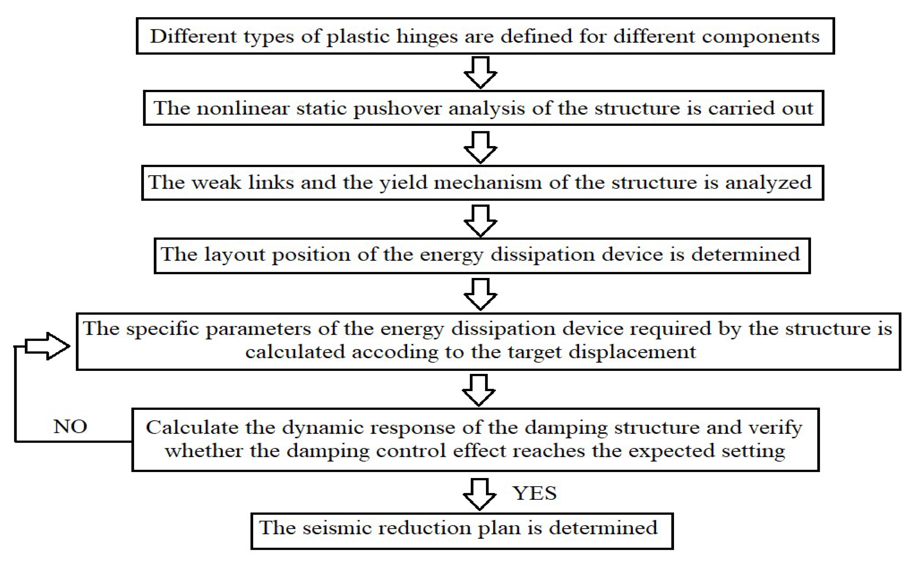
The columns of the frame structure are subject to both vertical load and horizontal seismic action, and the irregular shape and spatial layout of the building often result in an uneven distribution of the frame columns. Energy dissipation device design should be considered for structures where the regular requirements are not met by increasing the column section or reinforcement. The pushover method is used to determine the position of energy dissipation devices based on the structure’s yield mechanism. The device parameters are then adjusted in accordance with the seismic reduction target, ensuring that the entire structure exhibits a beam hinge yield mechanism and has met the seismic design target. The specific steps are as follows:
(1)
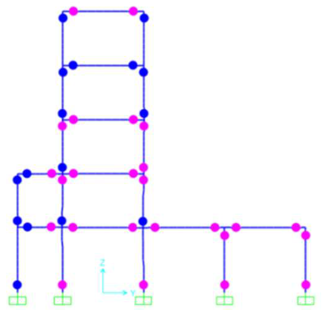
Establish structural modeling. SAP2000 V21 (Computers and Structures, Inc. (CSI), Berkeley, CA (California), USA) [31] software was employed to outline the characteristics and loads of the structural members. Four types of plastic hinges were defined: the moment hinge (M), shear hinge (V), axial force hinge (P), and P-M2-M3 hinge (PMM) [31]. These hinges simulate the plastic behavior of various structural components under different stress conditions. Different categories of plastic hinges are established according to the types of components and materials used. SAP2000 (V21) software utilizes four hinge types—the bending moment hinge (M), shear hinge (V), axial force hinge (P), and compression-bending hinge (PMM)—to model rods subject to varying stress states and materials. The frame beam primarily experiences bending moments and shear forces, so the bending moment and shear hinges were identified in the main force direction of the beam. The axial force in the frame column is associated with the bending moment. Thus, P-M2-M3 (PMM) hinges were employed for coupling. For simplicity, the location of the plastic hinge was set at 10% of L from the member’s end, as recommended in reference [31].
(2)
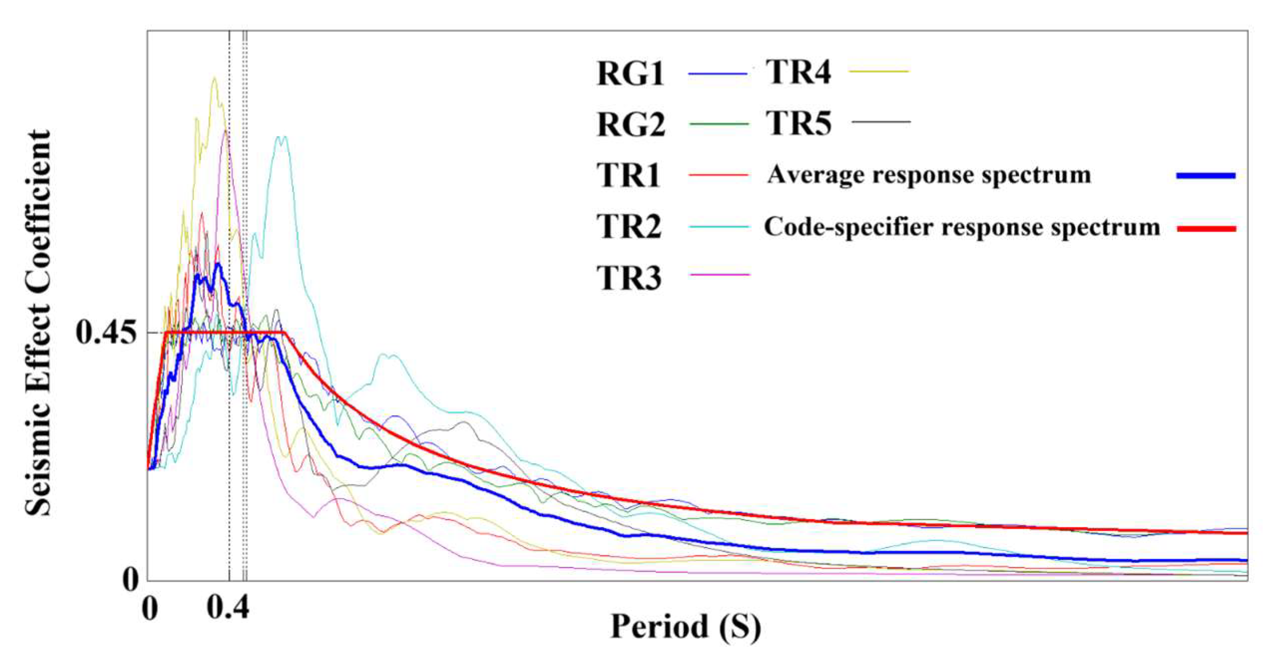
Use the pushover method to examine the uneven structure. The dead load and the design live load combined to create the vertical loads operating on the structure. These loads were evenly distributed over the frame beams and floor slabs. The horizontal loads applied to each floor were the floor shear forces. These shear forces were determined using the Square Root of the Sum of Squares (SRSS) method for multiple vibration modes after calculating the seismic actions of each floor of the structure with the mode-superposition response spectrum method. The loading procedure was controlled via displacement. Until the vertex displacement reached a value equal to the maximum load, the load was increased gradually. To account for the impact of high-order vibration modes on irregular structures, the combination should include a greater number of vibration modes. Specifically, the sum of the mass participation factors for each vibration mode should be greater than 90%. Furthermore, pushover analysis must be carried out independently in the X and Y dimensions since the dynamic properties of some irregular structures differ significantly in the longitudinal and transverse directions.
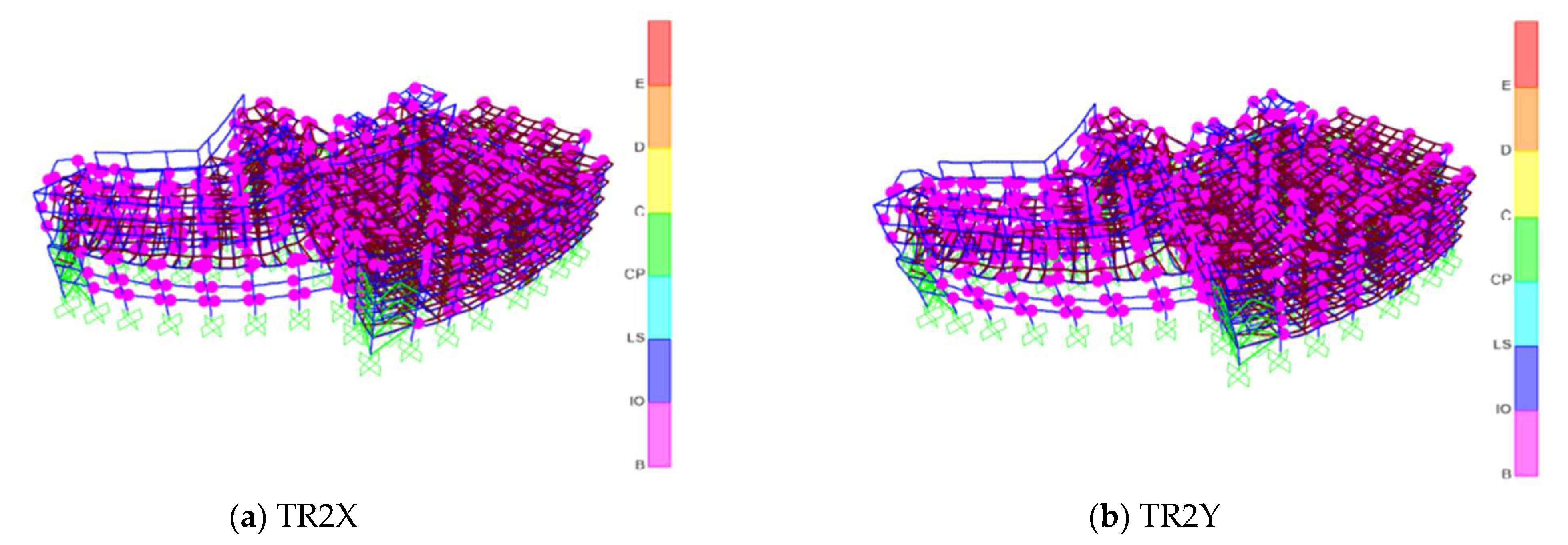
(3)
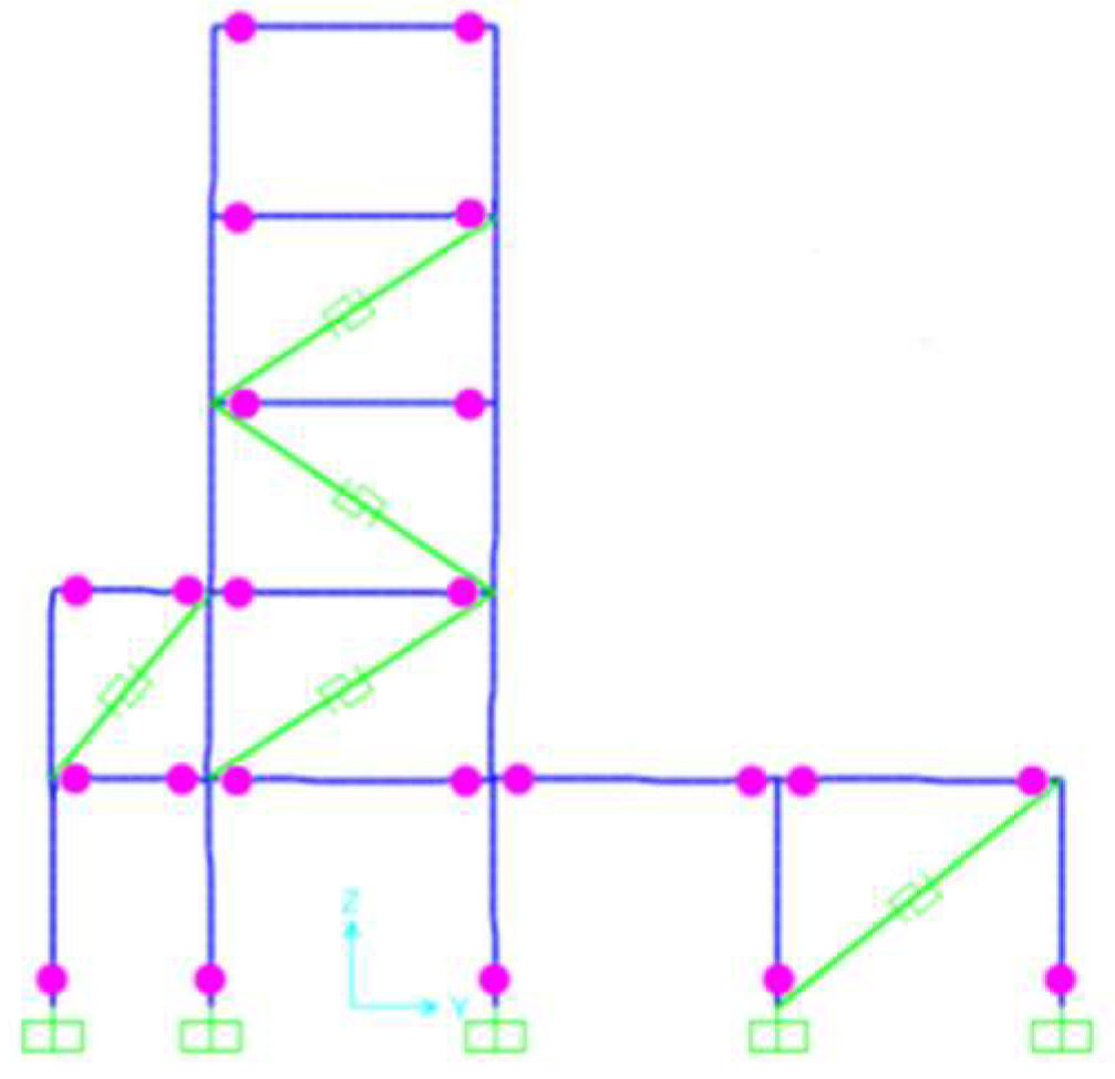
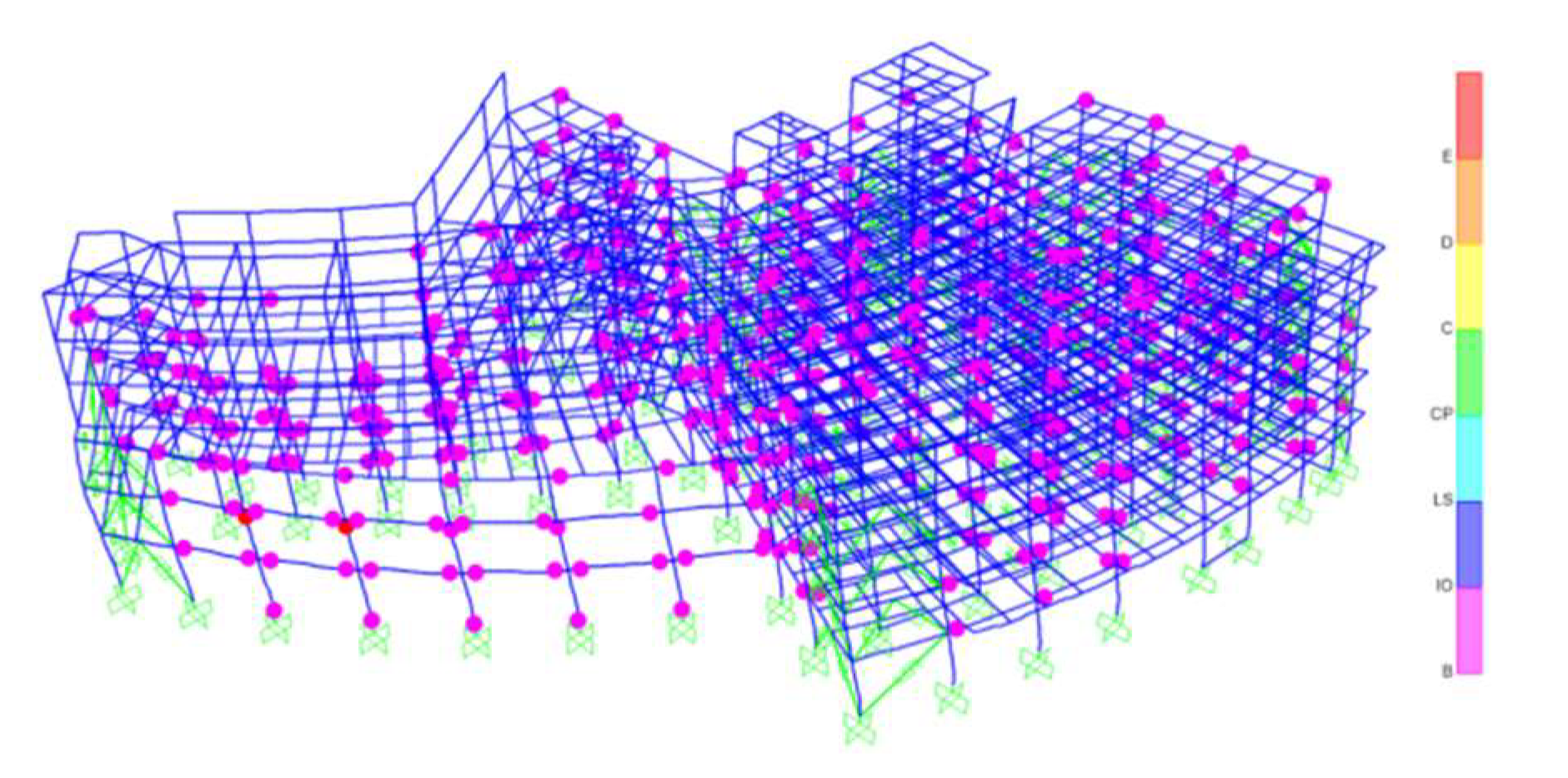
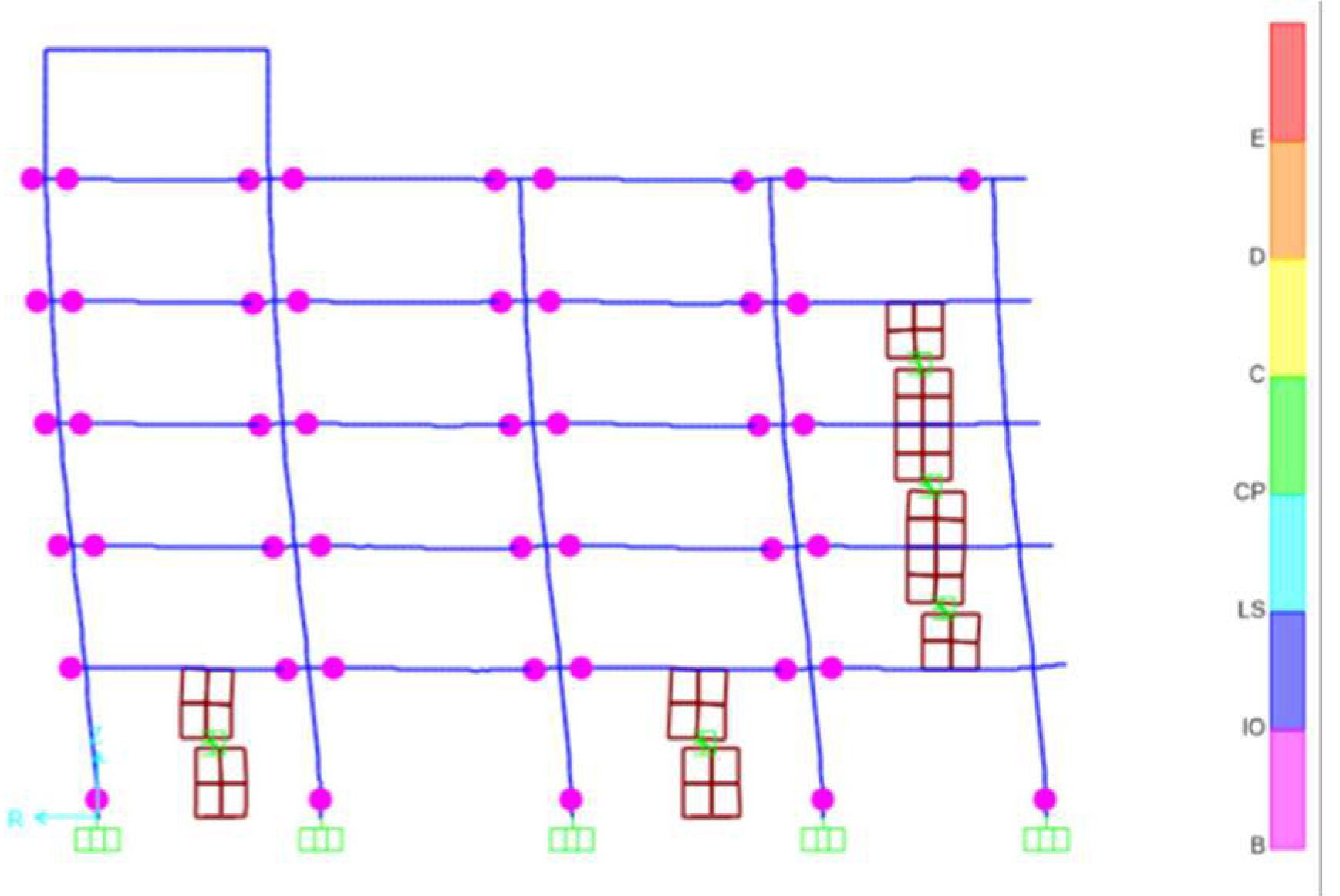
Determine the location of the energy dissipation devices. The structure’s yield mechanism was established based on the sequence in which plastic hinges developed during the pushover analysis. The areas of weakness highlighted by the concentration of plastic hinges indicate where energy dissipation devices should be positioned. Moreover, critical locations such as side spans, corners, and areas with shape alterations must also be equipped with these devices. The beam hinge yield mechanism should be achieved after the installation of energy dissipation devices in the originally irregular structure during an earthquake event.
(4)
Determine the parameters for the energy dissipation devices required by the structure. In SAP2000, the viscous damper, Nonlinear Fluid Viscous Damper (VFD-NL), is simulated using the Damper-Exponential connection element type, with the Maxwell model as the restoring force. This model is used to simulate the viscous damping phenomenon, which is characterized by a nonlinear force–velocity relationship. The Plastic (Wen) connection element type in SAP2000 simulates the BRBs, and the bilinear model is used to restore force.
The strain hardening component is incorporated into the bilinear model, as illustrated in Figure 4. The straight-line section that runs from Fdy to Fdmax indicates that the hardening behavior of the structure should be considered during the elastoplastic stage. The segment’s slope indicates how the post-hardening stiffness at this stage is considered. The effective stiffness, represented as Keff, is the slope of the straight line connecting the origin and peak of the hysteresis curve.
In accordance with the displacement-based damper design method [29], the displacement target was initially established by evaluating the structure’s seismic performance. The displacement response spectrum of the structure was then determined, together with the characteristics of the comparable single-degree-of-freedom system. The required equivalent damping ratio was subsequently determined. Formulas (1) and (2) [32] are used to determine the stiffness Kd and the damping coefficient Cn, respectively, when the viscous damper is used. Using Formulas (3) and (4), the stiffness Kd and yield load Fy were determined for BRBs, respectively.
ξ d 1 = 1 2 ɳ K d 0 n u o , n 2 0 n F n u n
C n = F n · T e 2 π u o , n  
ξ d 2 = 2 π 0 n F y , n u o , n 1 α n 1 1 μ n 0 n F n u n
K d = F y , n 1 + α n μ n 1 u o , n  
Herein, ξ d 1 and ξ d 2 are the equivalent damping ratios of FVD-NL and BRBs, C n is the damping coefficient, and K d is the stiffness of BRBs. ɳ is the loss factor, which is determined by the material of the viscous damper. u o , n and F n are the displacement and the shear force of the nth floor of the structure. T e is the period of the equivalent single-degree-of-freedom system, and α n is the post-buckling stiffness coefficient of the BRBs; the BRB type determines this parameter.
Check the damping effect. The structure equipped with energy dissipation devices was initially subjected to a pushover analysis to determine whether it adhered to the optimal beam hinge yield mechanism. Subsequently, dynamic time-history analysis was performed on both the original structure and the structure with an energy dissipation device using real strong earthquake records and artificial seismic waves tailored to the site’s characteristics. For both, the story drift ratios and inter-story shear forces were calculated and compared to establish if the damping effect met the intended control goal. If the target was not achieved, frequent parameter adjustments for the energy dissipation devices should be made, followed by dynamic time-history analyses, until the desired results are obtained.
Figure 5 presents the flow chart of the energy dissipation device design for irregular structures based on the yield mechanism.

4. Engineering Case

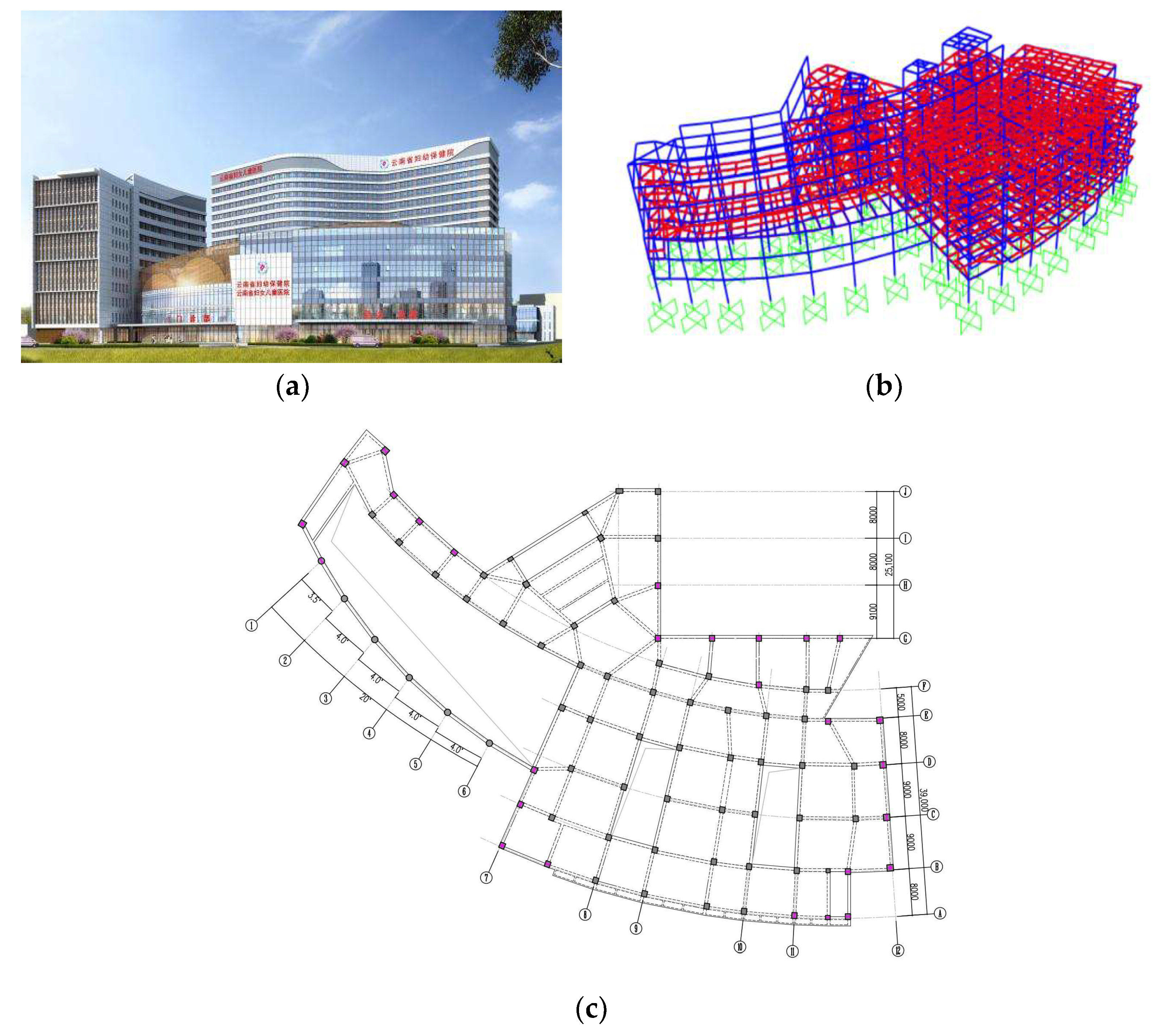
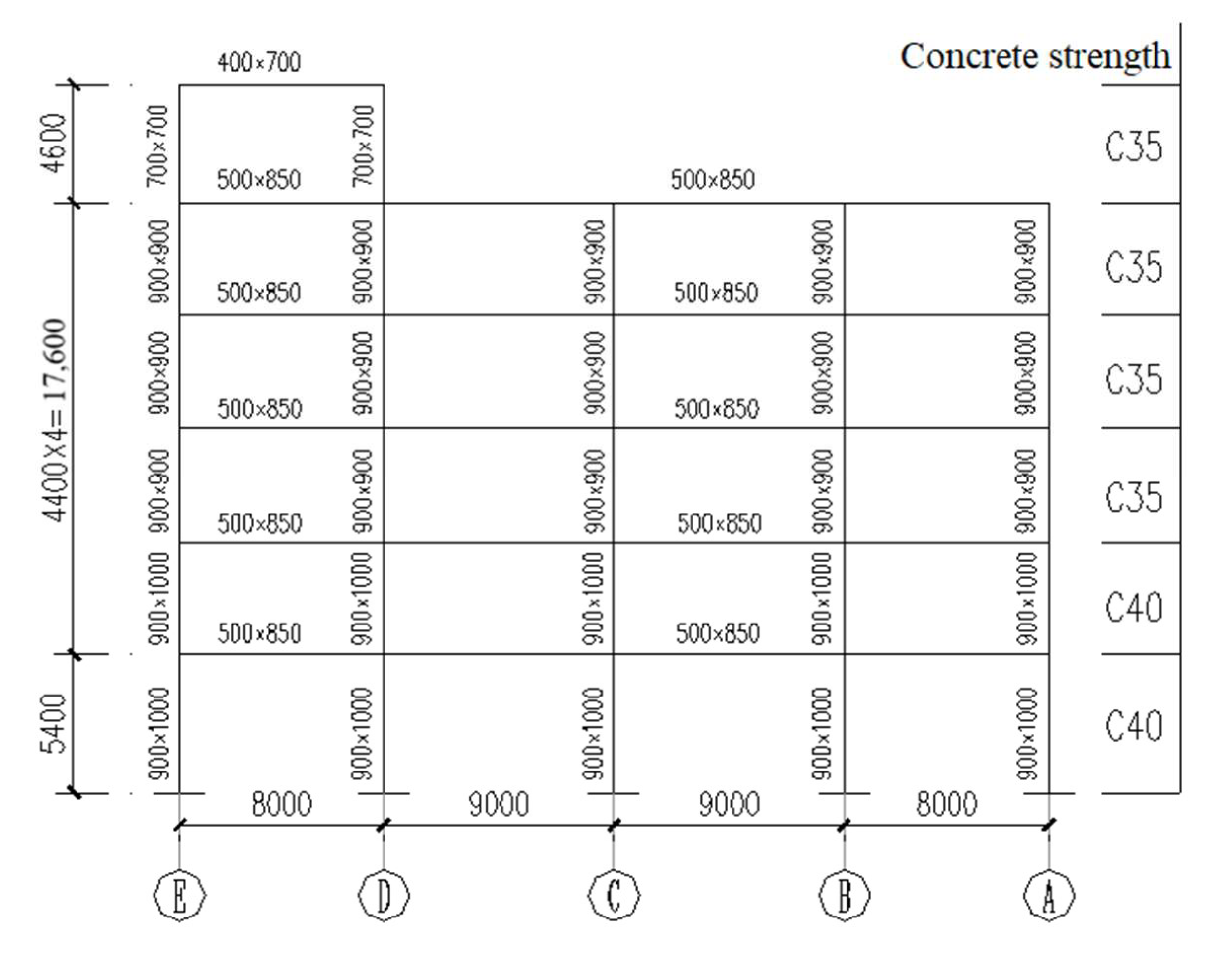
4.1. Engineering Situations

The structure is a five-story reinforced concrete frame hospital outpatient building. The first-floor height is 5.4 m, the second- to fifth-floor heights are 4.4 m, and the top-floor height is 4.6 m. The basic network of columns is 7.5 m by 8.0 m in size. According to the Chinese seismic zoning map, the design earthquake group is the first group, with a seismic precautionary intensity of 8 degrees and a design basic acceleration of ground motion of 0.2 g. According to the geological survey report, the site classification is III. In Figure 6, the structural system and the architectural facade are shown. The structural model was established in SAP2000. From bottom to top, the frame column’s section continuously reduces, and the concrete’s strength also gradually decreases. Thus, the lateral stiffness of the structure is larger at the lower part and smaller at the upper part. The structure plane’s convex dimension is greater than 30% of the corresponding side length, the floor opening area is roughly 25%, and the floor’s effective width is less than 50%. As a result, this structure has a highly irregular plane.

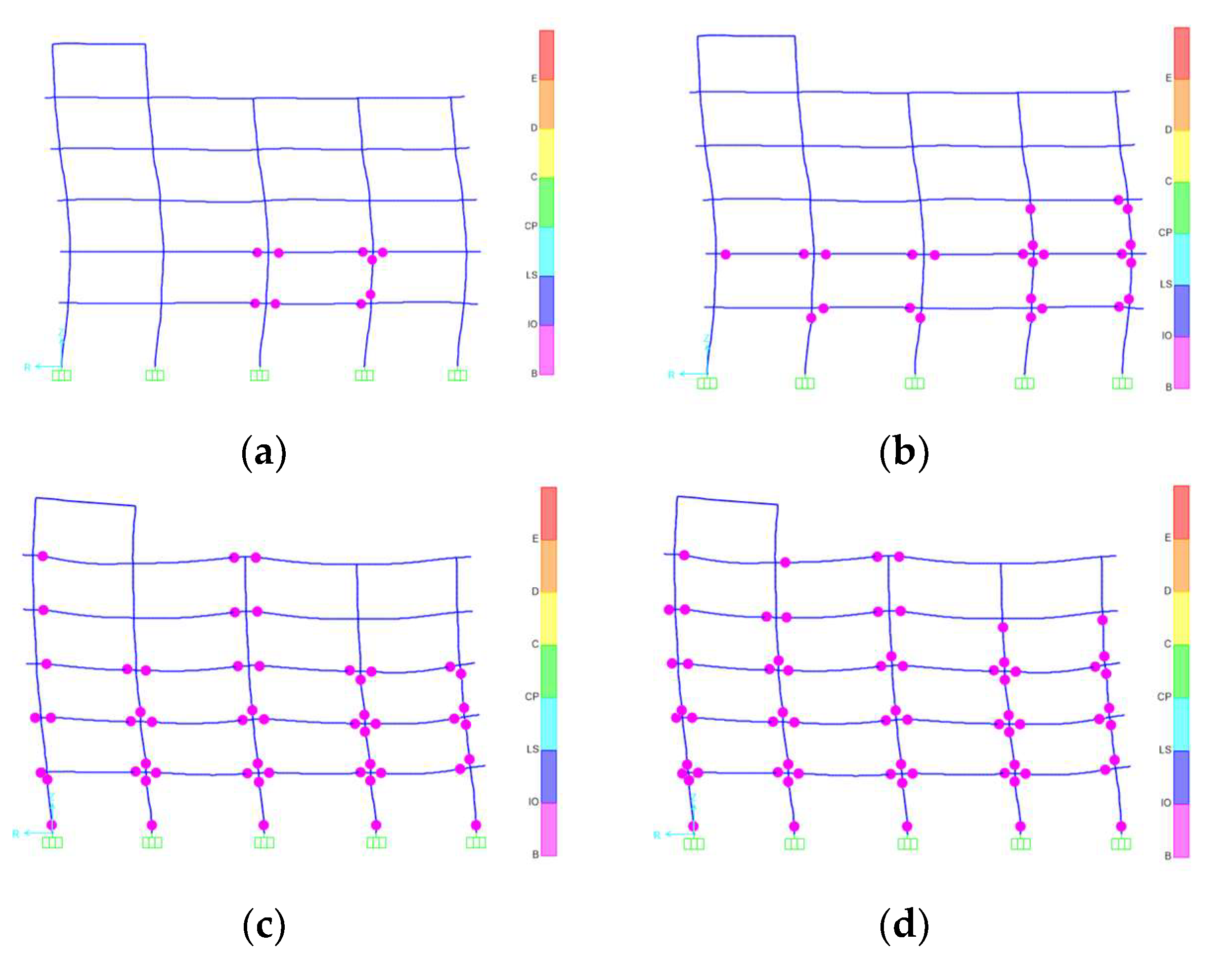
4.2. The Yielding Mechanism of the Structure

The structure undergoes pushover analysis. Figure 7 displays the section dimensions and material strengths. The analytical results are derived from the A–E span of the eighth-axis frame, as the opening in the slab alters the path of horizontal loads and increases the internal forces of the surrounding element members. The sections of the beams and columns are rectangular.
The sequence of plastic hinge appearance in the pushover analysis process of the structure is presented in Figure 8, where the B-D axis represents the opening area. The plastic hinges first appear at the second-floor B-axis column, and they also appear at the B-C beams that connect the first and second floors (Figure 8a). Plastic hinges appear at both ends of the B-axis and A-axis columns on the second and third floors, as well as at the top of the B-axis column on the first floor, and more of these emerge on the second-floor beams as the load increases (Figure 8b). The yielding of the D-axis column on the first floor initiates the yielding of the neighboring E-axis column, which then leads to the development of plastic hinges on the beams between the third and fifth floors (Figure 8c). Following this, the yielding of the B-axis columns from the first to the third floors prompts the A-axis and B-axis columns on the fourth floor to yield as well, resulting in the formation of plastic hinges on the B-E axis beams that span the third to fifth floors (Figure 8d). The plastic hinge envelope diagram for the structure is shown in Figure 9.
Many scholars have confirmed that the columns of structural frames pose risks at the edges of floor openings. Both the ground-floor BC and DE spans, as well as the second- to fourth-floor AB spans, include a column hinge yield mechanism. A column hinge yield mechanism can also be found at the edge of the structural plane, corners, and sites where the cross-section of the member changes concentrically. Dampers should be placed at these weak spots because this does not adhere to the design specifications.

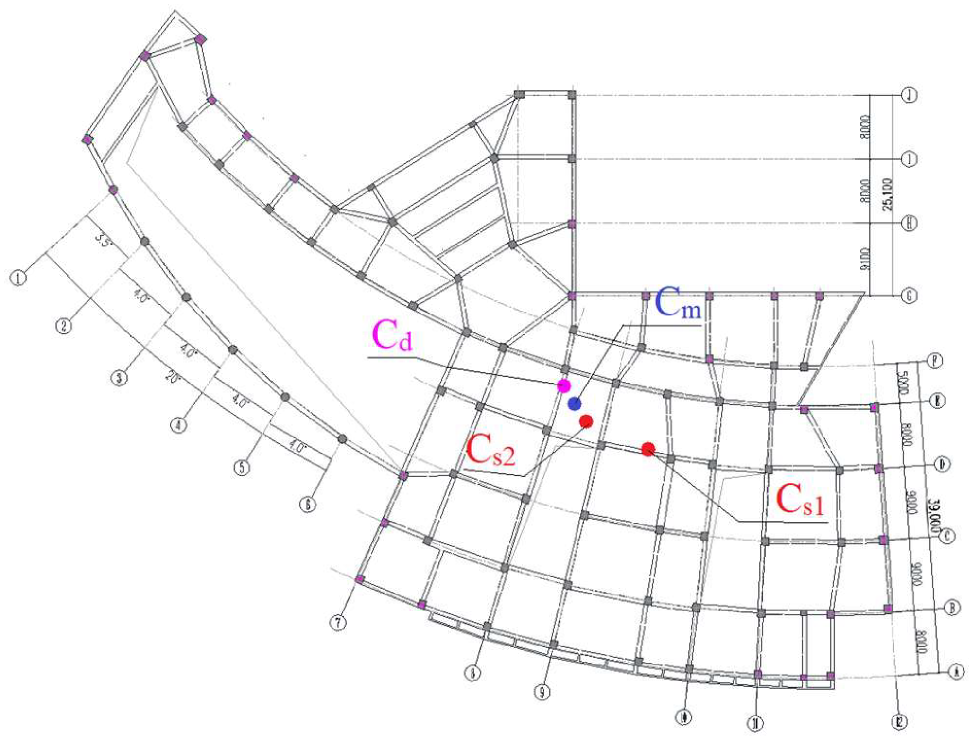
4.3. The Arrangement of Dampers

The first purpose of BRBs is to increase rigidity and reduce twisting at structural corner joints and section changes. Then, the positions of the viscous dampers at each floor level are determined based on the structural response mechanism, as depicted in Figure 10. The units of measurement for the geometric dimensions in the figure are millimeters (mm).
The Damper-Exponential connection element in SAP2000 is used to replicate VFD-NL, while the Plastic (Wen) connection element is used to replicate BRBs. Based on a target story drift angle of 1/100 under the rare earthquake action, the parameters of the two types of energy dissipation devices are computed. The dampers’ specifications and required quantities are shown in Table 1 and Table 2. (The parameters given in Table 1 and Table 2 are all results derived from the above formula).
The second floor of the original structure had a center of rigidity at (−56.792, 50.023) and a center of mass at (−67.97, 53.785). After the dampers were deployed, the mass and stiffness centers were recalculated, and then the damping strength center was calculated using Formula (5). The structure’s center of mass coordinates remained nearly unchanged, whereas the center of rigidity coordinates changed to (−65.558, 52.018), and the eccentricity decreased from 11.79 m to 2.71 m. The center of damping intensity was located at the coordinates (−69.89, 55.44), which, as shown in Figure 11, were nearly symmetrical with the center of stiffness with regard to the center of mass. Similar traits are also evident on other floors.
x d = i = 1 n y x i · F y i i = 1 n y F y i  
y d = i = 1 n x y i · F x i i = 1 n x F x i  
The variables xd and yd represent the coordinates of the center of the damping strength. The yield strengths of the ith damper in the x- and y-directions are denoted as Fxi and Fyi, respectively. The position coordinates for the ith damper are represented by xi and yi. Additionally, nx and ny indicate the number of dampers arranged in the x- and y-directions of the structure, respectively.
For another pushover analysis of the structure, the plastic hinge envelope model is depicted in Figure 12 and Figure 13, where the yield state is denoted by B, the limit states by C and D, the collapse state by E, the use safety state by LS, the direct yield state by IO, and the collapse prevention state by CP. No other columns, except for the bottom of the first-story frame columns, give when the dampers are installed, and the structure clearly displays a beam hinge yield mechanism.

4.4. Analysis of the Damping Effect

4.4.1. Seismic Response Analysis of the Original Structure

When conducting a time-history analysis, it is necessary to select real strong earthquake records and artificially created acceleration time-history curves that correspond to the site category and design earthquake grouping, as specified in Article 5.1.2 of the “Code for Seismic Design of Buildings”. The primary analytical data is often chosen from actual records, which should make up at least two-thirds of the total, in order to guarantee the data’s authenticity. Two artificially created accelerated time histories (RG1 and RG2) suitable for the site conditions are chosen to compute the seismic response of the structure, along with five real strong earthquake records (TR1–TR5). The average seismic influence coefficient curves for the seven earthquake waves are compared to the design response spectrum curves shown in Figure 14. The code criteria are met when the corresponding locations on the main structural modes deviate by no more than 20%. When an earthquake occurs, the seismic effect coefficient is the ratio of the acceleration response of a structure with different periods to the gravitational acceleration. It can explain how a structure reacts dynamically to an earthquake.
For dynamic time-history analysis, the seven seismic waves referred to above were introduced into the original construction. The average seismic responses are presented in Figure 15. Under regular earthquakes, the shear force varies greatly, and the majority of story drifts fall short of the requirements. The inter-story displacement angle between floors 2 and 5 changes noticeably during infrequent earthquakes.
The torsional displacement ratios along the X and Y axes are also higher than the required 1.2, at 1.3 and 1.32, respectively, indicating that the structure is twisted and uneven, which results in visible torsional effects during seismic activity.

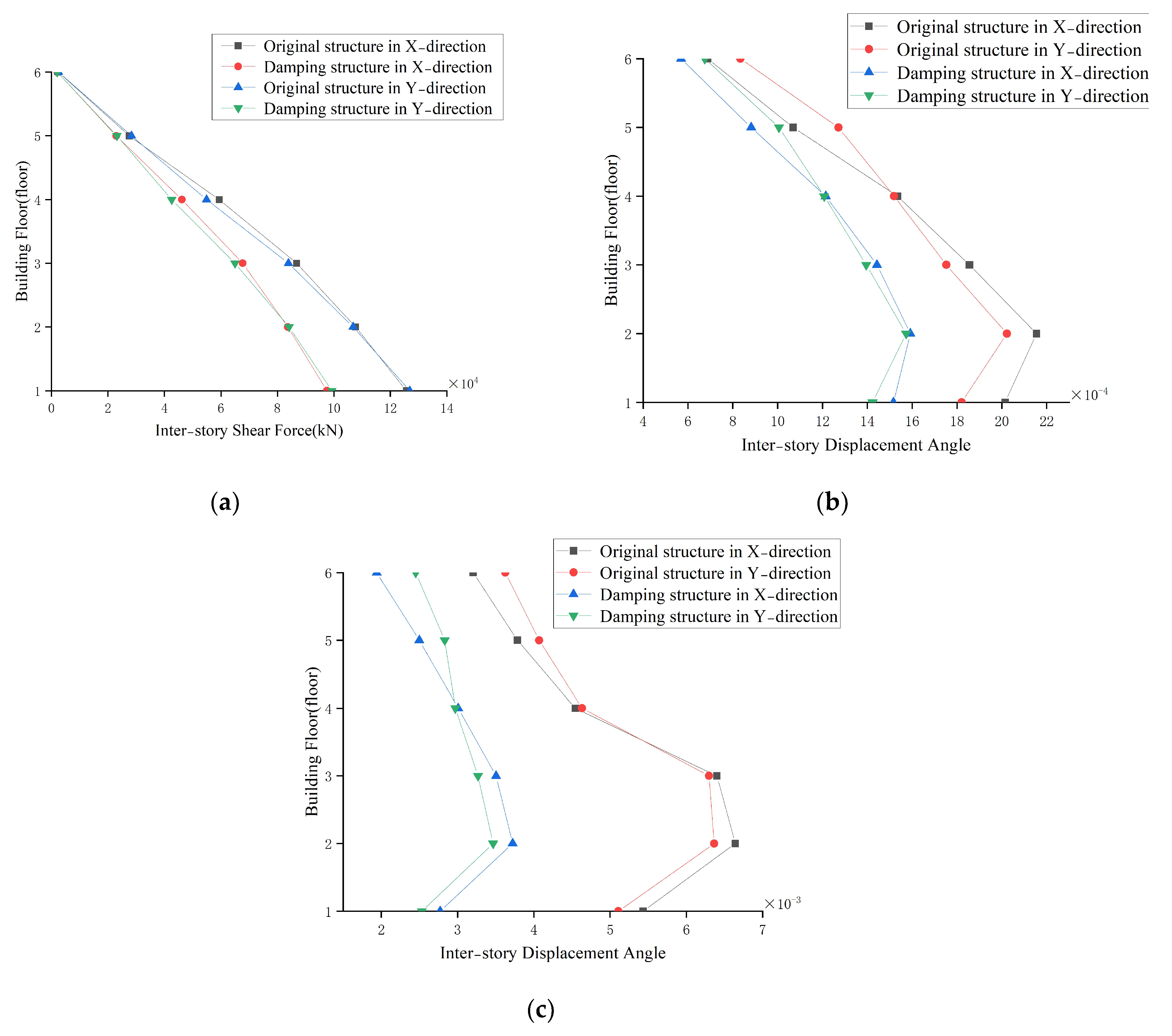
4.4.2. Seismic Responses and Effect of the Structure with an Energy Dissipation Device

The average seismic response calculated from the input of the seven seismic waves above into the damper−equipped structure was compared to the seismic response of the original structure, as illustrated in Figure 16.
When compared to the original structure, the damping structure’s inter−story shear force and inter−story displacement angle are both lower under frequent earthquakes, and the inter−story displacement angles of each floor meet all specification requirements. “Technical Specification for Energy Dissipation and Seismic Resistance of Buildings” requirements are met when the maximum inter−story displacement angle is lowered by more than 50%, from 0.01 to 0.004854, under infrequent earthquakes. The torsional effect of the damping structure is successfully controlled, and its torsional displacement ratio of 1.04 meets the specification requirement of 1.2.
A structure with an energy dissipation device must have a reasonable yield and energy dissipation mechanism under relatively rare earthquakes, according to the “Code for Seismic Design of Buildings”. Figure 17 illustrates the plastic hinge envelope diagram of the construction, which is produced by taking the natural wave TR2, which corresponds to rare earthquakes, and inserting it along the X− and Y−directions appropriately. It is evident that there are very few plastic hinges at the ends of the columns and that they are only present at the ends of the beams. As a result, the structure’s failure mechanism during rare earthquakes is a normal beam hinge yield mechanism consistent with design expectations.
The average analysis findings of the inter-story displacement angle and inter-story shear force under rare earthquakes are also compared with the performance-based seismic design approach in order to further demonstrate the efficacy of the seismic design method. Table 3 presents the comparison results.
The results indicate that the standard performance-based energy dissipation device design method and the yield-mechanism-based energy dissipation device design method are essentially the same, with negligible variation. The efficiency of the energy dissipation device design approach in this research is further demonstrated when combined with the seismic reduction effect previously examined.
To achieve the seismic performance of BRBFs, Incremental Dynamic Analysis and History Analysis can be utilized [33]. After the seismic wave is input, the hysteretic curve of the BRBs is fully developed, which plays a role in hysteretic energy dissipation. The BRBs have influenced energy dissipation.
According to the analysis results, the maximum internal forces in the reinforced concrete beam and column sections are all lower than the yield-bearing capacity, and these sections do not yield when subjected to the seismic waves corresponding to earthquakes that occur frequently. The beam ends initially exceed the yield-bearing capacity, plastic hinges appear in the frame beams, and finally, plastic hinges occur at the column roots with relatively significant internal forces when the intensity increases to that of several earthquakes.
There is still some safety margin because, after verification and computation, the capacity/demand ratio of the frame column with the highest force in this construction is 1.28 under a rare earthquake.
When conducting structural modeling, the site soil characteristics must be taken into account. The way that different soil types affect the superstructure’s seismic reaction varies [34]. The soil parameters corresponding to the site conditions were selected for the case study in this work. The backfill soil in engineering should also be treated to reach the required level of hardness. The parameters of the energy dissipation devices that are designed will change in accordance with changes in the type of site soil.

5. Conclusions

The seismic torsional effects induced by the irregular planar structure resulting from building design can be mitigated through the installation of energy dissipation devices, thereby controlling the overall seismic response of the structure. This work presents a design methodology for energy dissipation by altering the structural yield failure mechanism. It specifically involves employing pushover analysis to determine the feasible positions for energy dissipation devices, thereby evaluating the component yielding sequence. The structure’s shock absorption capabilities can be tailored to match the desired design objectives by carefully positioning and refining these devices. The following conclusions are obtained after an analysis of the application effect in the structural design of a hospital outpatient building:
  • Analyzing the component yield order enables a rapid and straightforward determination of the energy dissipation device’s location in structures with large floor holes and irregular plane shapes.
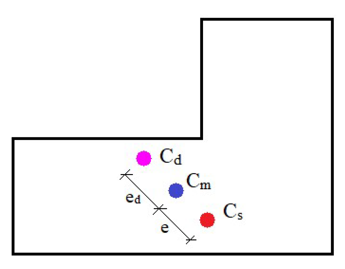
  • For a better damping effect, the damper parameters can be chosen based on the symmetry principle between the stiffness center and the damping strength center, both of which are located at the mass center.
  • The case project’s calculation results demonstrated that the structural torsional displacement ratio decreased from 1.32 to 1.04, and the displacement angle between layers decreased from 0.01 to 0.0048 following the assembly of the energy dissipation devices using this method.
  • This method is effective for designing multilayer frame structures with uneven planar shapes for shock absorption. Because huge building spaces are required, it is more difficult to determine the energy dissipation device design plan for structures with discontinuous vertical components. Therefore, future studies should focus on improving approaches in this area.

Author Contributions

Methodology, X.F., Y.B. and H.W.; Validation, L.C.; Investigation, Y.Q., Y.B. and L.C.; Data Curation, Y.Q. and Y.B.; Writing—Original Draft Preparation, X.F. and Y.B.; Writing—Review and Editing, H.W. and A.G. All authors have read and agreed to the published version of the manuscript.

Funding

National Key Research and Development Program of China “Quality Control Key Technologies and Integrated Application Demonstration of Essential Facilities for Building Seismic Isolation and Energy Dissipation” (Grant No. 2022YFF0608900).

Data Availability Statement

Data are contained within the article.

Conflicts of Interest

Author Yihang Bai was employed by the Jiaodong Company, The Fourth Construction Co., Ltd., of China Construction Eighth Engineering Division, and Author Liang Chen was employed by the Shandong Provincial Architecture Design & Research Institute Company Limited. The remaining authors declare that the research was conducted in the absence of any commercial or financial relationships that could be construed as a potential conflict of interest.

References

  1. Mazza, F.; Labernarda, R. Internal pounding between structural parts of seismically isolated buildings. J. Earthq. Eng. 2021, 26, 5175–5203. [Google Scholar] [CrossRef]
  2. Reem, H.; Anil, K.C. Lateral-Torsional Coupling in Earthquake Response of Frame Buildings. J. Struct. Eng. 1989, 115, 852–867. [Google Scholar]
  3. Bertero, V.-V. Overview of seismic risk reduction in urban areas: Role‚ importance‚ and reliability of current U.S. seismic codes performance-based engineering. In Proceedings of the China-U.S. Bilateral Workshop on Seismic Codes, Guangzhou, China, 3–7 December 1996. [Google Scholar]
  4. Qian, J.R. Seismic design concept and engineering examples of irregular high-rise buildings. Build. Struct. 1997, 35–37+45. [Google Scholar]
  5. Wei, L.; Wang, S.; Wei, C.J. Torsional Design Method of Asymmetric and Irregular Building Under Horizontal Earthquake Action. Build. Struct. 2005, 12–17. [Google Scholar]
  6. Lin, J.; Sun, S.; Wang, G. Behavior of Irregular Structure with Big Openings. Build. Struct. 2007, 37, 27–29. [Google Scholar]
  7. Wang, D.; Lv, X.L. Progress in study on inelastic torsional seimic response of asymmetric buildings. Earthq. Eng. Eng. Dyn. 2010, 30, 51–58. [Google Scholar]
  8. Zhang, X. Structural Torsion Effect Characteristic Study On L-plan Frame Structure Under Seismic Effect; Central South University of Forestry and Technology: Changsha, China, 2014. [Google Scholar]
  9. Feng, Y. Study on the Application of Frame-Shear Wall Structurein Super High-Rise Residential Building with Irregular Plane—Take a Residential Project with Papilionaceous Wasp-Waist Plane as an Example; South China University of Technology: Guangzhou, China, 2021. [Google Scholar]
  10. Federal Emergency Management Agency. Prestandard and Commentary for the Seismic Rehabilitation of Buildings: FEMA 356; Federal Emergency Management Agency: Washington DC, USA, 2000. [Google Scholar]
  11. EC8 Euro Code 8: Design of Structures for Earthquake Resistance-General Rules, Seismic Actions and Rules for Buildings; British Standards Institution: London, UK, 2003.
  12. American Society of Civil Engineers. Minimum Design Loads for Buildings and Other Structures: ASCE7-10; American Society of Civil Engineers: Washington DC, USA, 2010. [Google Scholar]
  13. JGJ 297-2013; Technical Specification for Seismic Energy Dissipation of Buildings. China Architecture & Building Press: Beijing, China, 2013.
  14. Liu, J.B. Research on the Design Theory of Buckling-Restrained Braces and Buckling-Restrained Braced Frames; Tsinghua University: Beijing, China, 2005. [Google Scholar]
  15. Cheng, G.; Yie, L.; Zhu, X. Analysis on Energy Dissipation Control for Eccentric Structure. Earthq. Resist. Eng. Retrofit. 2006, 28, 78–83. [Google Scholar]
  16. Men, J.J.; Shi, Q.X.; Zhou, Q. Method of performance based seismic evaluation for irregular plane reinforced concrete frame structures. China Civ. Eng. J. 2008, 41, 60–65. [Google Scholar]
  17. Japan Seismic Isolation Structure Association. Passive Damping Structure Design and Construction Manual; China Architecture & Building Press: Beijing, China, 2008; pp. 23–27. [Google Scholar]
  18. Fang, Y.Q.; Li, Y.M.; Weng, W.Z. Discussion about torsional design method based on torsional response analysis of building structures. Build. Struct. 2009, 39, 88–93. [Google Scholar]
  19. Lin, X.C.; Ye, L.P. Study on optimization of seismic design for RC frames based on member importance index. J. Build. Struct. 2012, 33, 16–21. [Google Scholar]
  20. Siva, N.E.; Nimmy, M.A.; Anitha, K.S.D. Analysis of Irregular Structures under Earthquake Loads. Procedia Struct. Integr. 2019, 14, 806–819. [Google Scholar]
  21. Liu, J.F. Cause analysis and improvement measures of torsional irregularity of typical buildings. Build. Struct. 2020, 50, 217–223. [Google Scholar]
  22. Wang, W.; Huang, X.N.; Wang, N. Research on torsion control of eccentric structure based on isolation technology. Earthq. Resist. Eng. Retrofit. 2020, 42, 83–89. [Google Scholar]
  23. Jin, Z.F.; Rong, Z.H.; Wu, Q. Structural design of out-of-code high-rise office building of Wenzhou Kaidi Center. Build. Struct. 2022, 52, 1–9. [Google Scholar]
  24. Du, Y.F.; Zhang, W.L.; Huang, X.N. Energy Dissipation Design of an Irregular-plane RC Frame Structure Based on the Load Path. China Earthq. Eng. J. 2017, 39, 0404–0411. [Google Scholar]
  25. Guerrero, H.; Teran-Gilmore, A.; Zamora, E.; Escobar, J.A.; Gómez, R. Hybrid simulation tests of a soft storey frame building upgraded with a buckling-restrained brace (BRB). Exp. Tech. 2020, 44, 553–572. [Google Scholar] [CrossRef]
  26. Mazza, F.; Labernarda, R. Seismic retrofitting of framed structures by damped braces considering the out-of-plane response of masonry infills. In Proceedings of the 9th ECCOMAS Thematic Conference on Computational Methods in Structural Dynamics and Earthquake Engineering, COMPDYN 2023, Athens, Greece, 12–14 June 2023; pp. 2261–2270. [Google Scholar]
  27. Lin, Y.; Tsai, M.; Hwang, J.; Chang, K. Direct displacement-based design for building with passive energy dissipation systems. Eng. Struct. 2003, 25, 25–37. [Google Scholar] [CrossRef]
  28. Dong, L. Study on “Strong-Column-Weak-Beam” Yield Mechanism of Reinforced Concrete Frame Structures; Southwest Jiaotong University: Chengdu, China, 2016. [Google Scholar]
  29. GB 50011-2010; Ministry of Housing and Urban-Rural Development of the People’s Republic of China. Code for Seismic Design of Buildings; China Architecture & Building Press: Beijing, China, 2010.
  30. Freeman, S.A.; Nicoletti, J.P.; Tyrdl, J.V. Evalution of existing buildings for seismic risk-a case study of puget sound nacal shipyard. In Proceedings of the U.S. National Conference on Earthquake Engineering, Ann Arbor, MI, USA, 18–20 June 1975; Volume 11, pp. 112–113. [Google Scholar]
  31. Peng, J. Structural Concept Analysis and Application of SAP2000; Southwest Jiaotong University Press: Chengdu, China, 2005. [Google Scholar]
  32. Qu, J.T. Studies on Seismic Behavior Comparison and Optimal Design of Displacement-Based and Velocity-Based Dampers; Dalian University of Technology: Liaoning, China, 2008. [Google Scholar]
  33. Asgarkhani, N.; Kazemi, F.; Jakubczyk-Gałczyńska, A.; Mohebi, B.; Jankowski, R. Seismic response and performance prediction of steel buckling-restrained braced frames using machine-learning methods. Eng. Appl. Artif. Intell. 2023, 128, 107388. [Google Scholar] [CrossRef]
  34. Asgarkhani, N.; Kazemi, F.; Jankowski, R. Machine learning-based prediction of residual drift and seismic risk assessment of steel moment-resisting frames considering soil-structure interaction. Comput. Struct. 2023, 289, 107181. [Google Scholar] [CrossRef]
Figure 1. The location indication of the mass center, the stiffness center, and the damping intensity center.
Buildings 15 02305 g001
Figure 2. Plastic hinge envelope diagram of the original irregular structure.
Buildings 15 02305 g002
Figure 3. The plastic hinge envelope diagram of the structure with BRBs. (The green parts are BRBs).
Buildings 15 02305 g003
Figure 4. Bilinear model (Proposed by Granger and Anderson).
Buildings 15 02305 g004
Figure 5. The process of energy dissipation device design.
Buildings 15 02305 g005
Figure 6. Structural model of the outpatient building. (a) Architectural elevation drawing. (b) Finite element model diagram. (c) Structural plane sheet. (The numbers in the circles represent the axis labels in the structural drawing).
Buildings 15 02305 g006
Figure 7. Information on the 8th axis frame structure (the figure’s geometric dimensions are measured in mm).
Buildings 15 02305 g007
Figure 8. Occurrence order of plastic hinges of No. 8 axis frame. (a) The first appearance of plastic hinges. (b) The number of plastic hinges starts to increase with the load. (c) The number of plastic hinges continues to increase. (d) All plastic hinges have appeared.
Buildings 15 02305 g008
Figure 9. Plastic hinge envelope diagram of the original structure.
Buildings 15 02305 g009
Figure 10. Layout diagram of dampers on each floor level. (a) The arrangement of the damper on first floor. (b) Schematic illustration of dampers for floors 2 to 4.
Buildings 15 02305 g010
Figure 11. The illustration of the positions of the mass center, the stiffness center, and the damping intensity center.
Buildings 15 02305 g011
Figure 12. The plastic hinge envelope diagram of the No. 8 axis frame.
Buildings 15 02305 g012
Figure 13. The plastic hinge envelope diagram of the damping structure.
Buildings 15 02305 g013
Figure 14. Comparison of the response spectra of 7 seismic waves and standard response spectra.
Buildings 15 02305 g014
Figure 15. The seismic responses of the original structure. (a) Inter−story shear force in the X-direction under frequent earthquakes. (b) Inter−story shear force in the Y-direction under frequent earthquakes. (c) The story drifts in the X-direction under frequent earthquakes. (d) The story drifts in the Y-direction under frequent earthquakes. (e) The story drifts in the X-direction under rare earthquakes. (f) The story drifts in the Y-direction under rare earthquakes.
Buildings 15 02305 g015
Figure 16. Comparison of seismic responses before and after damper installation. (a) Comparison of average inter−story shear force under frequent earthquakes. (b) Comparison of average story drift under frequent earthquakes. (c) Comparison of average story drift under rare earthquakes.
Buildings 15 02305 g016
Figure 17. The plastic hinge envelope diagram of the damping structure under a rare earthquake (a) TR2X. (b) TR2Y.
Buildings 15 02305 g017
Table 1. Parameters and quantity of viscous dampers.
ModelInitial Stiffness K (kN/mm)Damping Coefficient C
(kN·S/mm)
Damping Exponent αQuantity
VFD-NL40002000.261
Table 2. Parameters and quantity of BRBs.
ModelInitial Stiffness K (kN/mm)Yield Load (kN)Post-Yield Stiffness RatioQuantity
BRB16502000~45000.0353
BRB27402000~50000.03511
BRB38002500~35000.03510
BRB48701500~40000.0352
BRB510603000~55000.03526
BRB611503500~55000.03526
BRB712002500~40000.03512
BRB83002000~45000.0354
Total 94
Table 3. The comparison of rare earthquakes.
Energy Dissipation Device Design of Irregular Structures Based on Yield MechanismPerformance-Based Seismic Design
Interlayer Displacement AngleInterlaminar ShearInterlayer Displacement AngleInterlaminar Shear
X-DirectionY-DirectionX-DirectionY-DirectionX-DirectionY-DirectionX-DirectionY-Direction
0.0029070.002920116,603 kN112,590 kN0.0028960.002931116,597 kN112,593 kN
Disclaimer/Publisher’s Note: The statements, opinions and data contained in all publications are solely those of the individual author(s) and contributor(s) and not of MDPI and/or the editor(s). MDPI and/or the editor(s) disclaim responsibility for any injury to people or property resulting from any ideas, methods, instructions or products referred to in the content.

