Monitoring and Analysis of Mechanical Response of Main Tunnel Structure During Segment-Cutting Process
Abstract
1. Introduction
2. Project Overview
2.1. Geological Conditions
2.2. Main Tunnel Structure
2.3. Internal Support Structure
3. Simulation Model
3.1. Model Establishment
3.2. Model Parameter
3.3. Calculating Procedure
- (1)
- Initial stage: The excavation of the main tunnel is completed, and a displacement resetting operation is performed on the model.
- (2)
- Pre-support stage: The internal support structure and the launching sleeve are activated, and pre-support forces are applied to the main tunnel.
- (3)
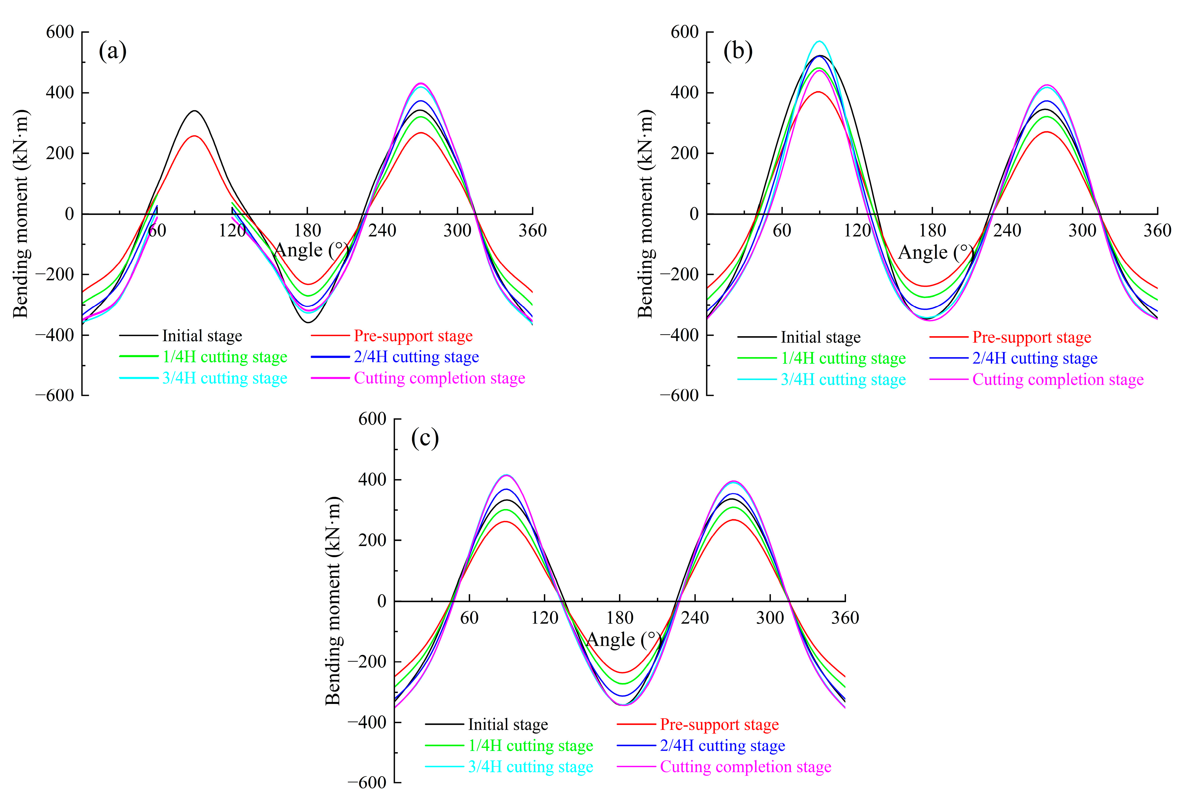
- Cutting stage: The thrust force of 2500 kN on the cutting face and the corresponding thrust reaction force of 2500 kN on the rear support plate are activated. The contact form between the cutter head of the pipe jacking machine and the main tunnel is illustrated in Figure 6. To analyze the mechanical changes in the main tunnel during the segment-cutting process, the thickness of the segment at the hole location (H = 350 mm) is divided into four equal parts. The cutting stage is further divided into four calculation steps, corresponding to 1/4 H (87.5 mm), 2/4 H (175 mm), 3/4 H (262.5 mm), and the full thickness H (350 mm).
3.4. Mesh Independence Verification
3.5. Model Validation
3.5.1. Field Monitoring
3.5.2. Comparative Analysis
4. Mechanical Response Analysis
4.1. Deformation
- (1)
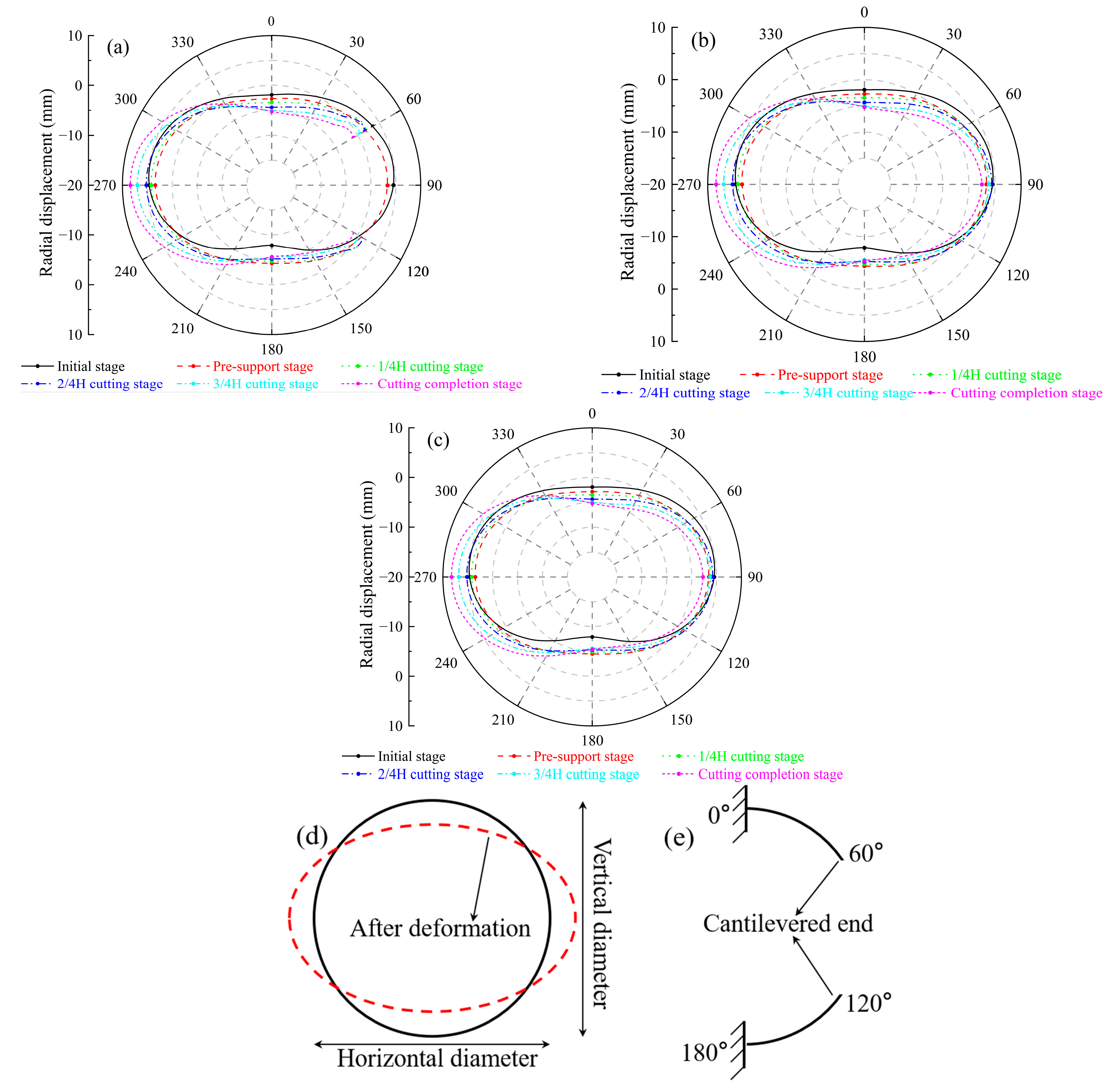
- Initial stage: The radial displacement of the main tunnel exhibits a “horizontal ellipse” distribution under the influence of self-weight and earth and water loads. This horizontal ovalization is characterized by a decrease in the tunnel’s vertical diameter and an increase in its horizontal diameter, as illustrated in Figure 12d. The vault of each ring experiences a settlement displacement of 1.9 mm, the arch bottom rises by 7.9 mm, and the left and right arch waists deform outward by 4.6 mm and 4.5 mm, respectively.
- (2)
- Pre-support stage: Under the combined effects of the self-weight of the internal support and the pre-support forces, the top of the tunnel experienced settlement, while the bottom deformed outward. Convergence deformation occurred on both sides of the tunnel. This reduced the transverse elliptical deformation of the tunnel, indicating that the internal support system provided a certain level of protection to the main tunnel.
- (3)
- Cutting stage: As the cutting thickness increases, the inward deformation at the vault and arch bottom of each ring gradually increases, while the outward deformation at the left arch waist gradually increases. The 60° and 120° positions of the right arch waist of the cutting ring gradually converge inward, exhibiting a significant cantilever effect. (where the structure is fixed at one end and free at the other, as depicted in Figure 12e). The radial displacement of the right arch waist in the semi-cutting ring and adjacent ring first increases and then decreases. This change is attributed to the reduced contact area between the segments being cut and the surrounding segments during the 3/4 H cutting stage, which significantly decreases the outward thrust of the cutter head on the segments near the breakthrough. Under the action of the internal support system, the radial deformations at the vault, arch bottom, and left arch waist of each ring are relatively similar. Due to the continuous horizontal thrust reaction force on the rear support plate, the left arch waist segments exhibit more pronounced outward deformation. Upon completion of the cutting, the maximum outward deformation of the left arch waist segment is approximately 8.4 mm. This value is less than the specified limit of 10 mm in the “Code for Design of Urban Rail Transit Tunnels” (GB 50911–2013). Therefore, the tunnel deformation is within a safe condition.
4.2. Bolts Stress
4.2.1. Circumferential Bolt Stress
4.2.2. Longitudinal Bolt Stress
4.3. Internal Forces
4.3.1. Axial Force
4.3.2. Bending Moment
5. Scope of Application
6. Conclusions
- (1)
- Under the load of water and soil pressure, the cutting ring, semi-cutting ring, and adjacent ring all exhibit a horizontal elliptical shape. After the application of pre-support force, the degree of horizontal ellipticity of each ring is somewhat reduced. As the cutting thickness increases, the vertical diameter of the tunnel near the opening decreases while the horizontal diameter expands. Under the influence of the jacking resistance, a noticeable outward deformation occurs at the 270° position of the left arch waist of the tunnel.
- (2)
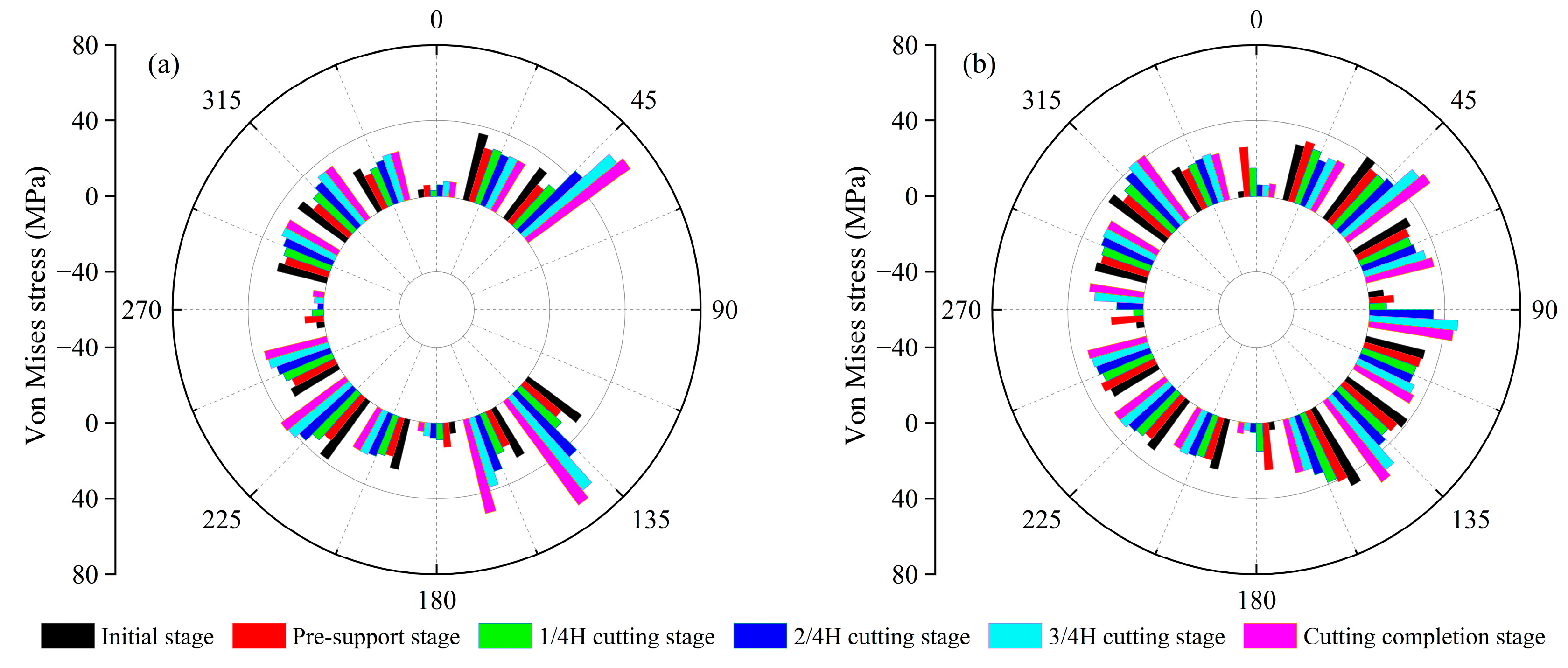
- As the cutting thickness gradually increases, the stress on the bolts in the main tunnel shows a consistent upward trend. Throughout this process, the stress on the circumferential bolts is significantly higher than that on the longitudinal bolts, indicating a greater concentration of stress in the circumferential bolts. Notably, the stress of the circumferential bolts near the opening rises to 550 MPa, which is approximately 86% of the yield strength of the bolts.
- (3)
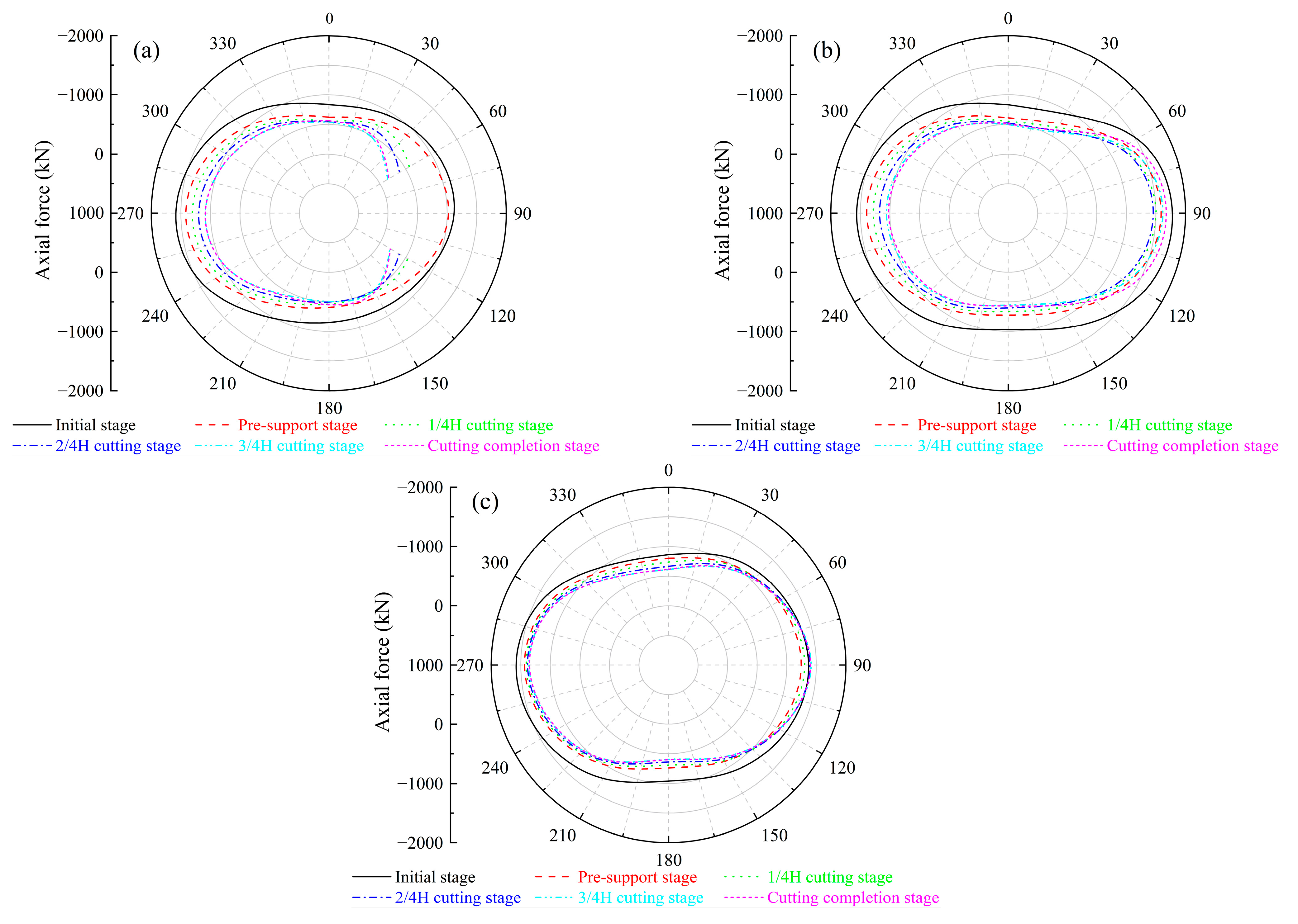
- In the pre-supporting stage, the internal force of the main tunnel gradually decreases. After entering the cutting stage, the axial force at the upper and lower ends of the cutting ring opening is gradually reduced to about 0 kN, forming a cantilever effect. The load lost by the cutting ring is transmitted to the adjacent ring through the longitudinal bolt, resulting in a significant change in the internal force at the 90° position of the arch waist on the right side of the semi-cutting ring. This internal force redistribution mainly occurs in the 3/4 H cutting stage.
Author Contributions
Funding
Data Availability Statement
Conflicts of Interest
References
- Cao, S.J.; Leng, J.; Qi, D.; Kumar, P.; Chen, T. Sustainable underground spaces: Design, environmental control and energy conservation. Energy Build. 2022, 257, 111779. [Google Scholar] [CrossRef]
- Qiao, Y.K.; Peng, F.L.; Sabri, S.; Rajabifard, A. Low carbon effects of urban underground space. Sustain. Cities Soc. 2019, 45, 451–459. [Google Scholar] [CrossRef]
- Cui, J.; Nelson, J.D. Underground transport: An overview. Tunn. Undergr. Space Technol. 2019, 87, 122–126. [Google Scholar] [CrossRef]
- Wang, L.; Chen, X.; Su, D.; Liu, S.; Liu, X.; Jiang, S.; Gao, H.; Yang, W. Mechanical performance of a prefabricated subway station structure constructed by twin closely-spaced rectangular pipe-jacking boxes. Tunn. Undergr. Space Technol. 2023, 135, 105062. [Google Scholar] [CrossRef]
- Wu, Y.Q.; Wang, K.; Zhang, L.Z.; Peng, S.H. Sand-layer collapse treatment: An engineering example from Qingdao Metro subway tunnel. J. Clean. Prod. 2018, 197, 19–24. [Google Scholar] [CrossRef]
- Zhang, S.; Cheng, X.; Yao, Y.; Zhu, K.; Li, K.; Lu, S.; Zhang, R.; Zhang, H. An experimental investigation on blockage effect of metro train on the smoke back-layering in subway tunnel fires. Appl. Therm. Eng. 2016, 99, 214–223. [Google Scholar] [CrossRef]
- Wang, H.; Gao, H. Study of blockage effects of metro train on critical velocity in sloping subway tunnel fires with longitudinal ventilation. Energies 2022, 15, 5762. [Google Scholar] [CrossRef]
- Feng, S.; Li, Y.; Hou, Y.; Li, J.; Huang, Y. Study on the critical velocity for smoke control in a subway tunnel cross-passage. Tunn. Undergr. Space Technol. 2020, 97, 103234. [Google Scholar] [CrossRef]
- Chen, T.B.Y.; Yuen, A.C.Y.; De Cachinho Cordeiro, I.M.; Liu, H.; Cao, R.; Ellison, A.; Yeoh, G.H. In-depth assessment of cross-passage critical velocity for smoke control in large-scale railway tunnel fires. Fire 2022, 5, 140. [Google Scholar] [CrossRef]
- Su, Z.; Li, Y.; Zhong, H.; Li, J.; Guo, Z.; Yang, X.; Yang, S. Advancements in smoke control strategies for metro tunnel cross-passage: A theoretical and numerical study on critical velocity and driving force. Tunn. Undergr. Space Technol. 2024, 147, 105734. [Google Scholar] [CrossRef]
- Liu, X.; Nowamooz, H.; Shen, Y.; Liu, Y.; Han, Y.; An, Y. Heat transfer analysis in artificial ground freezing for subway cross passage under seepage flow. Tunn. Undergr. Space Technol. 2023, 133, 104943. [Google Scholar] [CrossRef]
- Hou, S.; Yang, Y.; Cai, C.; Chen, Y.; Li, F.; Lei, D. Modeling heat and mass transfer during artificial ground freezing considering the influence of water seepage. Int. J. Heat Mass Transf. 2022, 194, 123053. [Google Scholar] [CrossRef]
- Li, Z.; Chen, J.; Sugimoto, M.; Ge, H. Numerical simulation model of artificial ground freezing for tunneling under seepage flow conditions. Tunn. Undergr. Space Technol. 2019, 92, 103035. [Google Scholar] [CrossRef]
- Zhou, J.; Zhao, W.; Tang, Y. Practical prediction method on frost heave of soft clay in artificial ground freezing with field experiment. Tunn. Undergr. Space Technol. 2021, 107, 103647. [Google Scholar] [CrossRef]
- Liu, X.; Shen, Y.; Zhang, Z.; Liu, Z.; Wang, B.; Tang, T.; Liu, C. Field measurement and numerical investigation of artificial ground freezing for the construction of a subway cross passage under groundwater flow. Transp. Geotech. 2022, 37, 100869. [Google Scholar] [CrossRef]
- Huang, D.W.; Chen, H.H.; Xu, C.J.; Feng, K.; Geng, D.X. Experimental study on influences of shield machine reception on existing shield tunnels during construction of connecting channels. Chin. J. Geotech. Eng. 2024, 46, 784–793. (In Chinese) [Google Scholar] [CrossRef]
- Li, X.; Li, P.; Liu, X.; Sun, L.; Cui, T.; He, K.; Guo, C. Surface subsidence pattern of construction of pipe jacking in water-rich sand layer cross passage measured and numerical simulation analysis. Structures 2024, 60, 105949. [Google Scholar] [CrossRef]
- Chen, X.; Ding, H.; Li, F.; Chen, X.; Gao, W.; Wang, H.; Wang, L.; Chen, H. Frost heave control measures for the frozen double-line tunnel undercrossing an operation station. J. China Coal Soc. 2024, 49, 172–180. (In Chinese) [Google Scholar] [CrossRef]
- Chen, P.; Liu, X.; Deng, Z.; Liang, N.; Du, L.; Du, H.; Deng, L.; Yang, G. Study on the pipe friction resistance in long-distance rock pipe jacking engineering. Undergr. Space 2023, 9, 173–185. [Google Scholar] [CrossRef]
- Wen, K.; Zeng, W.; Shimada, H.; Sasaoka, T.; Hamanaka, A. Numerical and theoretical study on the jacking force prediction of slurry pipe jacking traversing frozen ground. Tunn. Undergr. Space Technol. 2021, 115, 104076. [Google Scholar] [CrossRef]
- Deng, M.; Ding, F.; Liu, Y.; Huang, X.; He, Y.; Zhao, J. Surface settlement law of double-hole pipe-jacking tunnel undercrossing expressway. Sci. Rep. 2023, 13, 19286. [Google Scholar] [CrossRef]
- Ma, P.; Shimada, H.; Huang, S.; Moses, D.N.; Zhao, G.; Ma, B. Transition of the pipe jacking technology in Japan and investigation of its application status. Tunn. Undergr. Space Technol. 2023, 139, 105212. [Google Scholar] [CrossRef]
- Ding, J.; Dong, Z.; Mo, Z.; Jin, Y.; Ding, J.; Wang, N. Field experimental study on T-connected tunnel with pipe jacking method. Tunn. Constr. 2020, 40, 28–34. (In Chinese) [Google Scholar] [CrossRef]
- Li, Y.; Jin, X.; Lv, Z.; Dong, J.; Guo, J. Deformation and mechanical characteristics of tunnel lining in tunnel intersection between subway station tunnel and construction tunnel. Tunn. Undergr. Space Technol. 2016, 56, 22–33. [Google Scholar] [CrossRef]
- Yang, H.; Yu, L.; Wang, M.; Zhang, X. Analysis of mechanical response and failure characteristics of tunnels crossing active faults considering axial force and geometrical nonlinearity. Structures 2024, 64, 106583. [Google Scholar] [CrossRef]
- Zheng, H.; Li, P.; Ma, G.; Zhang, Q. Experimental investigation of mechanical characteristics for linings of twins tunnels with asymmetric cross-section. Tunn. Undergr. Space Technol. 2022, 119, 104209. [Google Scholar] [CrossRef]
- Gao, X.; Li, P.; Zhang, M.; Wang, H.; Jia, Z.; Feng, W. Effect of local openings on bearing behavior and failure mechanism of shield tunnel segments. Undergr. Space 2024, 16, 183–205. [Google Scholar] [CrossRef]
- Ke, W.; Shuaishuai, C.; Qianjin, Z.; Zheng, Z.; Jiahui, Z.; Yalin, Y. Mechanical mechanism analysis and influencing factors of subway cross passage construction. Lat. Am. J. Solids Struct. 2019, 16, e198. [Google Scholar] [CrossRef]
- Liu, J.; Shi, C.; Gong, C.; Lei, M.; Wang, Z.; Peng, Z.; Cao, C. Investigation of ultimate bearing capacity of shield tunnel based on concrete damage model. Tunn. Undergr. Space Technol. 2022, 125, 104510. [Google Scholar] [CrossRef]
- Zhao, S.; Wang, F.; Tan, D.; Yang, A. A deep learning informed-mesoscale cohesive numerical model for investigating the mechanical behavior of shield tunnels with crack damage. Structures 2024, 66, 106902. [Google Scholar] [CrossRef]
- Qian, W.; Tang, X.; Ma, X.; Wang, X. Mechanical Characteristics and Safety Evaluation of Tunnel Lining Structures in Karst Areas Under Heavy Rainfall Conditions. Buildings 2025, 15, 1756. [Google Scholar] [CrossRef]
- Liu, X.; Gao, Y.; Zhang, J.; Zhu, Y. Structural response of main tunnel linings during construction of connecting aisle by means of mechanized drilling. Chin. J. Geotech. Eng. 2020, 42, 951–960. (In Chinese) [Google Scholar] [CrossRef]
- Zhu, Y.; Gao, Y.; Dong, Z.; Liu, X. Full-scale experimental study on structural mechanism of T-connected tunnel constructed by pipe jacking method. Tunn. Constr. 2019, 39, 1392–1401. (In Chinese) [Google Scholar] [CrossRef]
- Lu, P.; Yuan, D.; Jin, D.; Luo, W.; Liu, M. Centrifugal model tests on the structural response of the shield tunnel when constructing cross passages by mechanical methods. Tunn. Undergr. Space Technol. 2022, 128, 104621. [Google Scholar] [CrossRef]
- Wang, J.; Li, F.; Chen, Z.; Li, B.; Zhu, J. Finite element analysis of T-joint of mechanical connecting channels. Adv. Mech. Eng. 2020, 12, 1–13. [Google Scholar] [CrossRef]
- Zhuo, Y.; Zou, D.; Chen, K.; Qu, Y.; Yi, G.; Tian, S. Improved double-phase-field algorithm based on scaled boundary finite element method for rock-like materials. Theor. Appl. Fract. Mech. 2025, 138, 104916. [Google Scholar] [CrossRef]
- Chen, K.; Zou, D.; Yi, G.; Nie, X.; Qu, Y. A flexible mixed-order formula for tetrahedron elements based on SBFEM. Comput. Geotech. 2024, 171, 106390. [Google Scholar] [CrossRef]
- Niu, X.; Xing, H.; Li, W.; Song, W.; Xie, Z. Impact of Multi-Defect Coupling Effects on the Safety of Shield Tunnels and Cross Passages. Buildings 2025, 15, 1696. [Google Scholar] [CrossRef]
- Wang, S.; Zhang, G.; Yu, Z.; Ya, Z. Numerical Study on Hydraulic Coupling and Surrounding Rock Deformation for Tunnel Excavation Beneath Reservoirs. Buildings 2025, 15, 1693. [Google Scholar] [CrossRef]
- Wu, X.; Sun, M.; Xia, Y.; Han, H.; Sun, Z. Research on evaluation method of lining safety based on ultimate bearing capacity curve of lining section. China J. Highw. Transp. 2020, 33, 160–169. (In Chinese) [Google Scholar] [CrossRef]







| Soil Layer Name | Thickness h/(m) | Unit Weight γ/(kN/m³) | Cohesion c/(kPa) | Internal Friction Angle φ/(°) | Compression Modulus E0/(kPa) | Poisson’s Ratio |
|---|---|---|---|---|---|---|
| A1 miscellaneous fill | 0.8 | 18.0 | 11.2 | 16.5 | 8000 | 0.35 |
| A2 plain fill | 1.4 | 18.5 | 12.8 | 18.2 | 8200 | 0.36 |
| A31 clayey silt | 2.8 | 19.1 | 12.1 | 22.3 | 9000 | 0.35 |
| A51 fine sand | 6.0 | 19.5 | 1 | 30 | 15,000 | 0.36 |
| A52 fine sand | 22.5 | 19.8 | 2 | 32 | 20,000 | 0.36 |
| Structure Name | Elastic Modulus /GPa | Unit Weight /(kN/m3) | Poisson’s Ratio |
|---|---|---|---|
| C50 concrete segment | 34.5 | 25 | 0.20 |
| steel-concrete composite segment | 60 | 35 | 0.22 |
| Glass fiber-reinforced concrete segment | 31.5 | 25 | 0.20 |
| Internal support system and bolt | 206 | 78.5 | 0.25 |
| Model Size | Number of Elements | Computation Time (h) |
|---|---|---|
| 60 m (X) × 46.5 m (Y) × 40 m (Z) | 289,536 | 4.8 |
| 70 m (X) × 61.5 m (Y) × 40 m (Z) | 398,056 | 6.3 |
| 80 m (X) × 76.5 m (Y) × 40 m (Z) | 465,824 | 8.5 |
Disclaimer/Publisher’s Note: The statements, opinions and data contained in all publications are solely those of the individual author(s) and contributor(s) and not of MDPI and/or the editor(s). MDPI and/or the editor(s) disclaim responsibility for any injury to people or property resulting from any ideas, methods, instructions or products referred to in the content. |
© 2025 by the authors. Licensee MDPI, Basel, Switzerland. This article is an open access article distributed under the terms and conditions of the Creative Commons Attribution (CC BY) license (https://creativecommons.org/licenses/by/4.0/).
Share and Cite
Liu, X.; Zang, Q.; Zi, X.; Ji, M.; Yu, C. Monitoring and Analysis of Mechanical Response of Main Tunnel Structure During Segment-Cutting Process. Buildings 2025, 15, 2175. https://doi.org/10.3390/buildings15132175
Liu X, Zang Q, Zi X, Ji M, Yu C. Monitoring and Analysis of Mechanical Response of Main Tunnel Structure During Segment-Cutting Process. Buildings. 2025; 15(13):2175. https://doi.org/10.3390/buildings15132175
Chicago/Turabian StyleLiu, Xiaofeng, Quansheng Zang, Xuanxuan Zi, Mingcong Ji, and Changyi Yu. 2025. "Monitoring and Analysis of Mechanical Response of Main Tunnel Structure During Segment-Cutting Process" Buildings 15, no. 13: 2175. https://doi.org/10.3390/buildings15132175
APA StyleLiu, X., Zang, Q., Zi, X., Ji, M., & Yu, C. (2025). Monitoring and Analysis of Mechanical Response of Main Tunnel Structure During Segment-Cutting Process. Buildings, 15(13), 2175. https://doi.org/10.3390/buildings15132175


