


Numerical and Experimental Multi-Approach Models for a Stone Pinnacle Reinforcement

Abstract
:1. Introduction
2. Structural Analysis
2.1. Basics
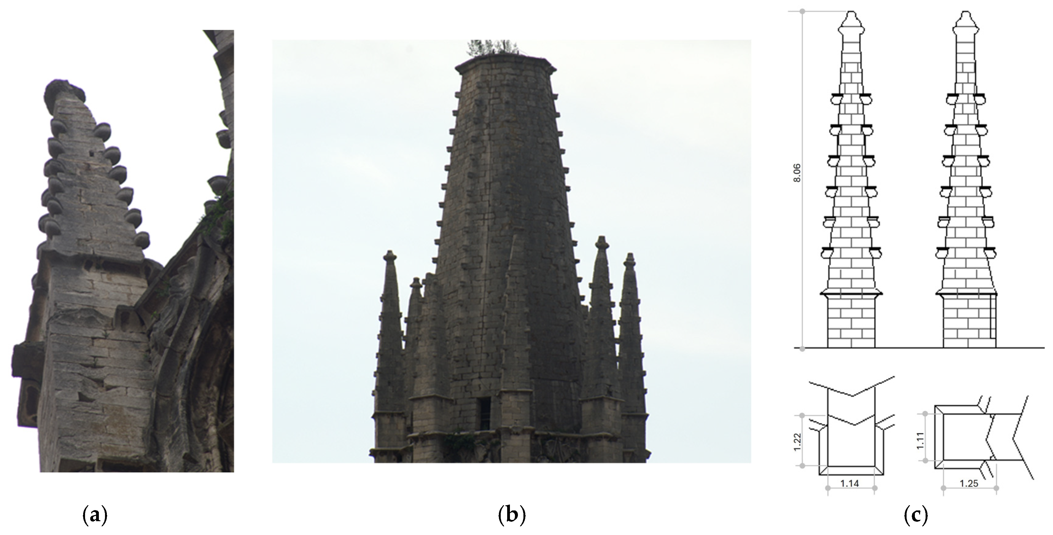
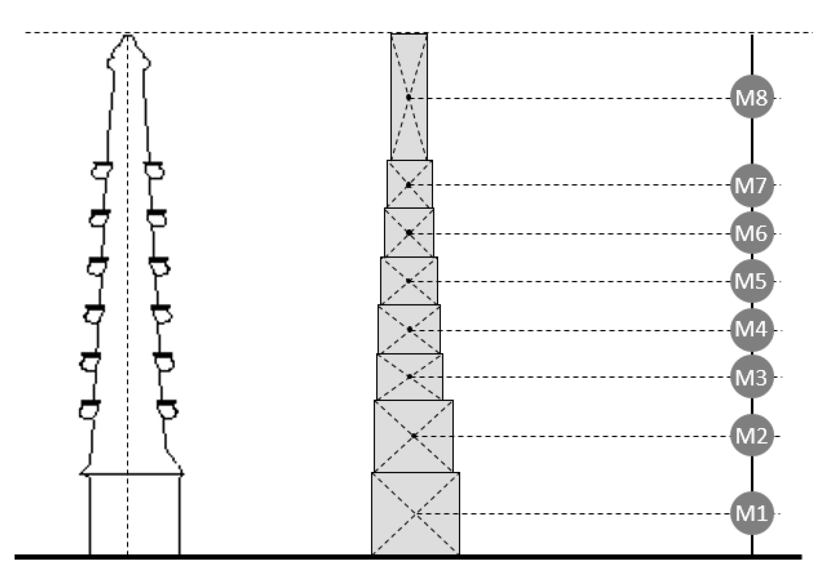
2.2. Geometry
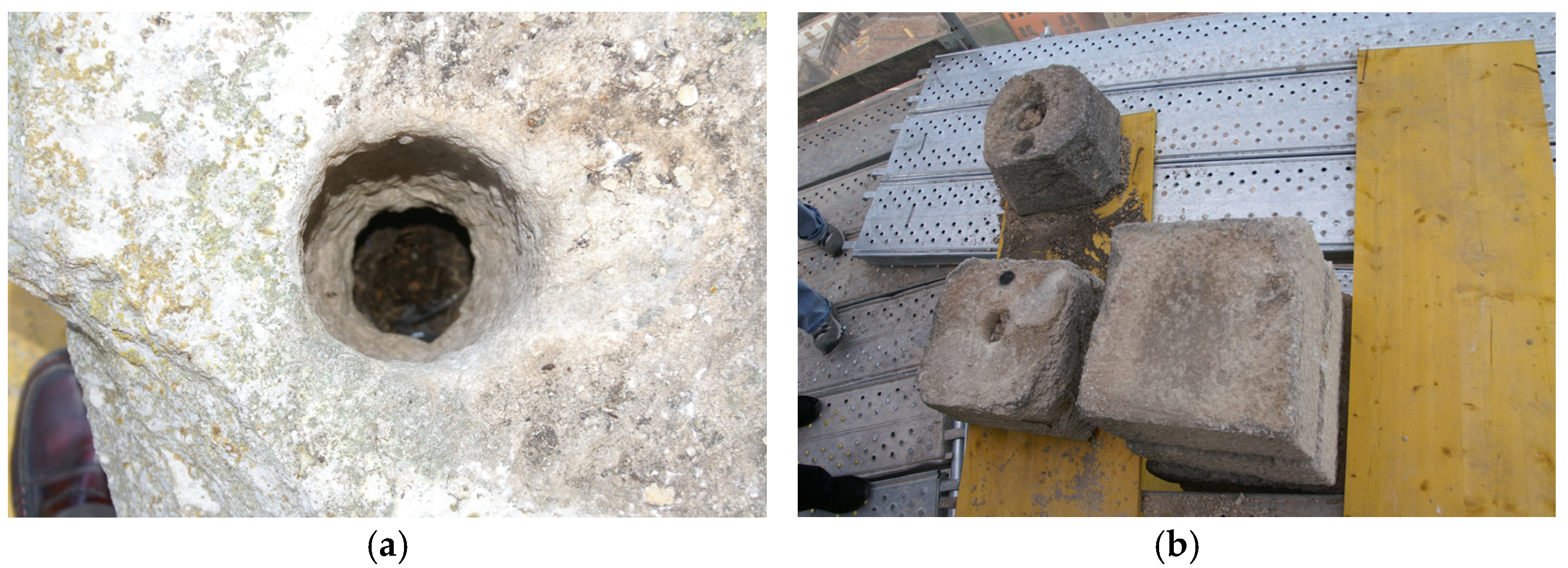
2.3. Stone of Girona
2.4. Load Estimation
2.4.1. Gravitational Forces
2.4.2. Wind Forces
2.4.3. Seismic Forces
3. Analysis Approaches
3.1. Introduction
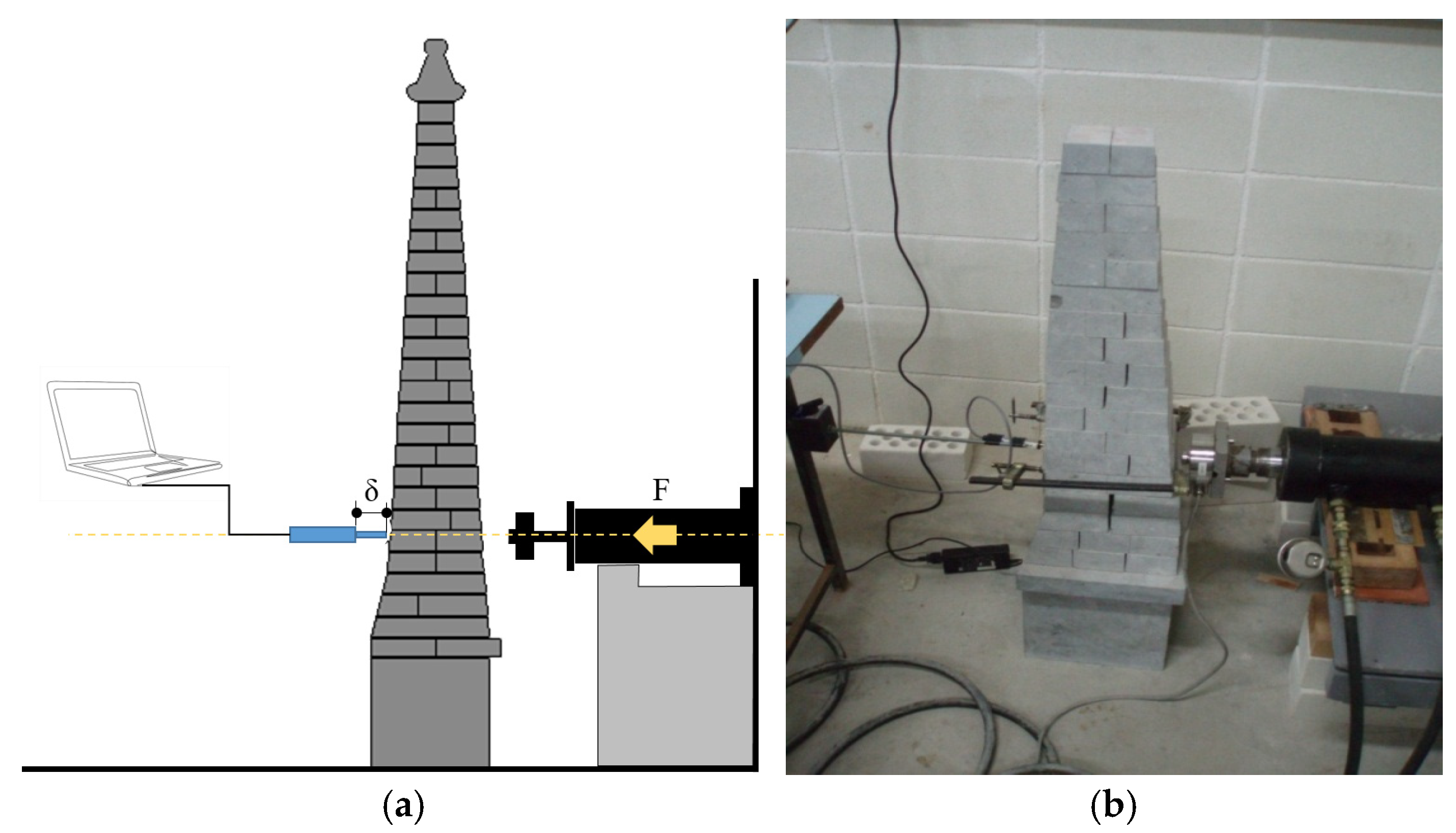
3.2. Experimental Scaled Model
- a
- A horizontal load was applied to the fifth course starting from the top of the scale model until sliding was detected. A force of 340 N was obtained.
- b
- A horizontal load was applied to the top of the base until a vertical displacement—due to rotation—of 1.0 mm relative to the ground, was measured. The applied force was 330 N.
3.3. Numerical Scaled Model
3.4. Frictional Model
3.5. Contact Model
3.6. Scale Model Adjustments and Full-Scale Model
3.7. Equilibrium Approach
3.8. Result of Overturning Analysis
3.9. Result of Sliding Analysis
4. Design of Reinforcement
4.1. Inner Bar
4.2. Filler
5. Conclusions
Author Contributions
Funding
Data Availability Statement
Acknowledgments
Conflicts of Interest
References
- Chamorro Trenado, M.A.; Zaragozá Catalán, A. La traza de la torre campanario de la iglesia de San Félix de Gerona. Goya Rev. De Arte Publicación Bimest. De La Fund. Lázaro Gald. 2012, 338, 3–15. [Google Scholar]
- Chamorro, M.À.; Soler, J.; Ripoll, R.; Vilagran, E. Vilagran, Building contracts in the city of girona from the fourteenth to the eighteenth century. In Proceedings of the 6th International Congress on Construction History (6ICCH 2018), Brussels, Belgium, 9–13 July 2018; pp. 449–456. [Google Scholar] [CrossRef]
- Chamorro Trenado, M.À. The Construction of the Saint Felix Church Tower in Girona, During the Fourteenth Century: Workers, Materials and Equipment. In Proceedings of the Third International Congress on Construction History, NEUNPLUS1, Cottbus, Germany, 20–24 May 2009; pp. 347–354. [Google Scholar]
- Chamorro, M.A.; Llorens, F. Els Campanars gòtics a les comarques gironines; Diputació de Girona: Girona, Spain, 1993. [Google Scholar]
- Ruggiero, G.; Marmo, R.; Nicolella, M. A Methodological Approach for Assessing the Safety of Historic Buildings’ Façades. Sustainability 2021, 13, 2812. [Google Scholar] [CrossRef]
- Vakis, A.I.; Yastrebov, V.A.; Scheibert, J.; Nicola, L.; Dini, D.; Minfray, C.; Almqvist, A.; Paggi, M.; Lee, S.; Limbert, G.; et al. Modeling and simulation in tribology across scales: An overview. Tribol. Int. 2018, 125, 169–199. [Google Scholar] [CrossRef]
- Funari, M.F.; Silva, L.C.; Savalle, N.; Lourenço, P.B. A concurrent micro/macro fe-model optimized with a limit analysis tool for the assessment of dry-joint masonry structures. Int. J. Multiscale Comput. Eng. 2022, 20, 65–85. [Google Scholar] [CrossRef]
- Costa, I.; Llorens, J.; Chamorro, M.À.; Fontàs, J.; Soler, J.; Gifra, E.; Savalle, N. Experimental Study of Mechanical Behavior of Dry-Stone Structure Contact. Buildings 2024, 14, 3744. [Google Scholar] [CrossRef]
- Lourenço, P.B.; Oliveira, D.V.; Roca, P.; Orduña, A. Dry joint stone masonry walls subjected to in-plane combined loading. J. Struct. Eng. 2005, 131, 1665–1673. [Google Scholar] [CrossRef]
- Fonti, R. Heritage for a sustainable future—The theoretical principle of reversibility and its reflections on architecture. Agathon—Int. J. Archit. Art Des. 2024, 16, 144–155. [Google Scholar] [CrossRef]
- Balaban Okten, B.; Haydaroglu, C.; Benzoni, G. Structural engineering perspective on historic building restoration. Proc. Int. Struct. Eng. Constr. 2016, 3, 583–587. [Google Scholar] [CrossRef]
- Turk, J.; Mauko Pranjić, A.; Hursthouse, A.; Turner, R.; Hughes, J.J. Decision support criteria and the development of a decision support tool for the selection of conservation materials for the built cultural heritage. J. Cult. Herit. 2019, 37, 44–53. [Google Scholar] [CrossRef]
- Corradi, M.; Di Schino, A.; Borri, A.; Rufini, R. A review of the use of stainless steel for masonry repair and reinforcement. Constr. Build. Mater. 2018, 181, 335–346. [Google Scholar] [CrossRef]
- Salmeron Escobar, P. Intervención en los pináculos de la Catedral de Jaén. Cuadernos de Arte de La Universidad de Granada. 1992, pp. 597–614. Available online: https://revistaseug.ugr.es/index.php/caug/article/view/10946 (accessed on 26 March 2025).
- Micelli, F.; Cascardi, A.; Aiello, M.A. A removable use of FRP for the confinement of heritage masonry columns. Mater. Struct. 2023, 56, 184. [Google Scholar] [CrossRef]
- Aiello, M.A.; Bencardino, F.; Cascardi, A.; D’Antino, T.; Fagone, M.; Frana, I.; La Mendola, L.; Lignola, G.P.; Mazzotti, C.; Micelli, F.; et al. Masonry columns confined with fabric reinforced cementitious matrix (FRCM) systems: A round robin test. Constr. Build. Mater. 2021, 298, 123816. [Google Scholar] [CrossRef]
- Cascardi, A.; Dell’Anna, R.; Micelli, F.; Lionetto, F.; Aiello, M.A.; Maffezzoli, A. Reversible techniques for FRP-confinement of masonry columns. Constr. Build. Mater. 2019, 225, 415–428. [Google Scholar] [CrossRef]
- Alecci, V.; De Stefano, M.; Galassi, S.; Luciano, R.; Pugliese, D.; Stipo, G. Influence of Different Mortar Matrices on the Effectiveness of FRCM Composites for Confining Masonry Columns. J. Test. Eval. 2022, 51, 735–750. [Google Scholar] [CrossRef]
- Yazdani, N.; Beneberu, E.; Mohiuddin, A.H. CFRP retrofit of concrete circular columns: Evaluation of design guidelines. Compos. Struct. 2018, 202, 458–464. [Google Scholar] [CrossRef]
- Thiagarajan, G. Experimental and Analytical Behavior of Carbon Fiber-Based Rods as Flexural Reinforcement. J. Compos. Constr. 2003, 7, 64–72. [Google Scholar] [CrossRef]
- Hua, K.; Ding, H.; Sun, L.; Cao, Y.; Li, X.; Wu, H.; Wang, H. Enhancing high-temperature fretting wear resistance of TC21 titanium alloys by laser cladding self-lubricating composite coatings. J. Alloys Compd. 2024, 977, 173360. [Google Scholar] [CrossRef]
- Wang, H.; Ban, C.; Zhao, N.; Kang, Y.; Qin, T.; Liu, S.; Cui, J. Enhanced strength and ductility of nano-grained titanium processed by two-step severe plastic deformation. Mater. Lett. 2020, 266, 127485. [Google Scholar] [CrossRef]
- Shen, Y.; Hesham El Naggar, M.; Zhang, D.; Huang, Z.; Du, X. Optimal intensity measure for seismic performance assessment of shield tunnels in liquefiable and non-liquefiable soils. Undergr. Space 2025, 21, 149–163. [Google Scholar] [CrossRef]
- Curti, E.; Podestá, S.; Scandolo, L. Simplified mechanical model for the seismic vulnerability evaluation of belfries. Int. J. Archit. Herit. 2012, 6, 605–625. [Google Scholar] [CrossRef]
- Funari, M.F.; Mehrotra, A.; Lourenço, P.B. A tool for the rapid seismic assessment of historic masonry structures based on limit analysis optimisation and rocking dynamics. Appl. Sci. 2021, 11, 942. [Google Scholar] [CrossRef]
- ASCE/SEI 41-06; Seismic Rehabilitation of Existing Buildings. American Society of Civil Engineers: Reston, VA, USA, 2007. [CrossRef]
- Pinto Puerto, F. La reconstrucción de los pináculos y gárgolas de la iglesia de Santiago de Jerez de la Frontera (1961–1965). Revista de Historia de Jerez 2022, 25, 235–254. [Google Scholar]
- Ellis, B.R. Non-destructive dynamic testing of stone pinnacles on the palace of westminster. Proc. Inst. Civ. Eng.—Struct. Build. 1998, 128, 300–307. [Google Scholar] [CrossRef]
- Heyman, J. The Mansonry Arch. 1982. Available online: https://archive.org/details/masonryarch0000heym/page/n7/mode/2up (accessed on 26 March 2025).
- Norma, D.C.S. Parte general y edificación (NCSE-02). BOE 2002, 244, 2. [Google Scholar]
- Documento Básicao SE-A. Código Técnico de Edificación. Documento Básicao de Seguridad Estructural; Acero. Ley. 2006. No. 38. Available online: https://www.codigotecnico.org/pdf/Documentos/SE/DBSE-A.pdf (accessed on 26 March 2025).
- Esbert Alemany, R.M.; Marcos Fierro, R.M.; Ordaz Gargallo, J.; Montoto San Miguel, M.; Suárez del Río, L.M.; Gómez Ruiz de Argandoña, V.; Calleja Escudero, L.; Alonso Rodríguez, F.J.; Rodríguez Rey, Á.M. Petrografía, propiedades físicas y durabilidad de algunas rocas utilizadas en el patrimonio monumental de Catalunya (España). Materiales de construcción 1989, 39, 37–47. [Google Scholar] [CrossRef]
- Verges Roig, S. Analisis de la pedra de Girona y comparació amb la pedra de Sant Vicenç; Final Degree Project; Universitat de Girona: Girona, Spain, 1998. [Google Scholar]
- Cocking, S.; Price, S.; DeJong, M. The effects of wind on the loading and vibration of stone pinnacles. Mason. Int. 2017, 29, 53–60. [Google Scholar]
- Dawood, A.O.; Sangoor, A.J.; Al-Rkaby, A.H.J. Behavior of tall masonry chimneys under wind loadings using CFD technique. Case Stud. Constr. Mater. 2020, 13, e00451. [Google Scholar] [CrossRef]
- Jansen, L.; Korswagen, P.A.; Bricker, J.D.; Pasterkamp, S.; de Bruijn, K.M.; Jonkman, S.N. Experimental determination of pressure coefficients for flood loading of walls of Dutch terraced houses. Eng. Struct. 2020, 216, 110647. [Google Scholar] [CrossRef]
- Heyman, J. The vibration of masonry pinnacles. Trans. Built Environ. 1997, 26, 429–436. Available online: https://www.witpress.com/Secure/elibrary/papers/STR97/STR97041FU.pdf (accessed on 26 March 2025).
- EN 1991; Eurocode 1: Actions on Structures. European Committee for Standardization: Brussels, Belgium, 2009.
- Bartoli, G.; Betti, M.; Facchini, L.; Orlando, M. Non-destructive characterization of stone columns by dynamic test: Application to the lower colonnade of the Dome of the Siena Cathedral. Eng. Struct. 2012, 45, 519–535. [Google Scholar] [CrossRef]
- Grazzini, A.; Fasana, S.; Zerbinatti, M.; Lacidogna, G. Non-destructive tests for damage evaluation of stone columns: The case study of sacro monte in ghiffa (Italy). Appl. Sci. 2020, 10, 2673. [Google Scholar] [CrossRef]
- Ivorra, S.; Pallarés, F.J.; Adam, J.M. Masonry bell towers: Dynamic considerations. Proc. Inst. Civ. Eng. Struct. Build. 2011, 164, 3–12. [Google Scholar] [CrossRef]
- Casapulla, C.; Giresini, L.; Lourenço, P.B. Rocking and kinematic approaches for rigid block analysis of masonry walls: State of the art and recent developments. Buildings 2017, 7, 69. [Google Scholar] [CrossRef]
- Casapulla, C.; Argiento, L.U. In-plane frictional resistances in dry block masonry walls and rocking-sliding failure modes revisited and experimentally validated. Compos. Part B Eng. 2018, 132, 197–213. [Google Scholar] [CrossRef]
- Szemerey-Kiss, B.; Török, Á. Failure mechanisms of repair mortar stone interface assessed by pull-off strength tests. Bull. Eng. Geol. Environ. 2017, 76, 159–167. [Google Scholar] [CrossRef]
- Ramos, N.M.M.; Simões, M.L.; Delgado, J.M.P.Q.; De Freitas, V.P. Reliability of the pull-off test for in situ evaluation of adhesion strength. Constr. Build. Mater. 2012, 31, 86–93. [Google Scholar] [CrossRef]
- UNE-EN1997-1; Eurocode 7: Geotechnical Design. European Committee for Standardization: Brussels, Belgium, 2016.
- Documento Básico SE-C. Codigo Tecnico de la Edificacion (CTE). Documento Basico de Seguredad Estructural; Cimientos. Ley. 2006. No. 38. Available online: https://www.codigotecnico.org/pdf/Documentos/SE/DBSE-C.pdf (accessed on 26 March 2025).


| Property | Value |
|---|---|
| density | 27.00 kN/m3 |
| absorption coefficient | 0.30% |
| compression strength (generic value) | 73.20 MPa |
| bending strength | 9.00 MPa |
| Direction of Effort | Compression Values | ||
|---|---|---|---|
| White Stone [MPa] | Blue Stone [MPa] | Grey Stone [kMPa] | |
| Perpendicular to the vein | 100.60 | 131.60 | 111.90 |
| Parallel to the vein | 84.40 | 95.30 | 108.00 |
| Flexural Stress Values | |||
|---|---|---|---|
| White Stone [MPa] | Blue Stone [MPa] | Grey Stone [kMPa] | |
| Parallel to the vein | 9.50 | 12.00 | 10.20 |
| Element | Height (m) | X Dimension (m) | Y Dimension (m) | Volume (m3) | Weight (KN) | Accumulated (KN) | egeometric (m) |
|---|---|---|---|---|---|---|---|
| 1 | 1.28 | 1.11 | 1.32 | 1.88 | 50.64 | 169.02 | 0.10 |
| 2 | 1.11 | 1.06 | 1.18 | 1.38 | 37.31 | 118.38 | 0.05 |
| 3 | 0.74 | 0.96 | 0.97 | 0.69 | 18.51 | 81.07 | 0.00 |
| 4 | 0.74 | 0.88 | 0.90 | 0.58 | 15.74 | 62.57 | 0.00 |
| 5 | 0.74 | 0.80 | 0.82 | 0.48 | 13.02 | 46.83 | 0.00 |
| 6 | 0.74 | 0.71 | 0.74 | 0.39 | 10.50 | 33.80 | 0.00 |
| 7 | 0.74 | 0.63 | 0.67 | 0.31 | 8.37 | 23.31 | 0.00 |
| 8 | 1.97 | 0.52 | 0.54 | 0.55 | 14.94 | 14.94 | 0.00 |
| Element | Force Wind (m) | Bending Moment Wind (kNm) | ewind (m) |
|---|---|---|---|
| 1 | 2.10 | 33.49 | 0.20 |
| 2 | 1.80 | 21.16 | 0.19 |
| 3 | 1.10 | 14.83 | 0.14 |
| 4 | 1.00 | 10.54 | 0.16 |
| 5 | 0.90 | 7.28 | 0.17 |
| 6 | 0.80 | 4.66 | 0.18 |
| 7 | 0.70 | 2.81 | 0.19 |
| 8 | 1.50 | 1.44 | 0.20 |
| Element | H (m) | ϕ | Weight (kN) | η1 | S1 | F1 (KN) | M1 (kNm) | eseismic [m] |
|---|---|---|---|---|---|---|---|---|
| 1 | 56.30 | 0.02 | 50.64 | 0.96 | 0.08 | 4.10 | 39.05 | 0.23 |
| 2 | 57.50 | 0.02 | 37.31 | 0.97 | 0.08 | 3.00 | 23.88 | 0.20 |
| 3 | 58.40 | 0.02 | 18.51 | 0.97 | 0.08 | 1.50 | 15.01 | 0.19 |
| 4 | 59.10 | 0.02 | 15.74 | 0.97 | 0.08 | 1.30 | 10.27 | 0.16 |
| 5 | 59.90 | 0.02 | 13.02 | 0.98 | 0.08 | 1.10 | 6.83 | 0.15 |
| 6 | 60.60 | 0.02 | 10.50 | 0.98 | 0.08 | 0.90 | 4.21 | 0.12 |
| 7 | 61.30 | 0.02 | 8.37 | 0.99 | 0.08 | 0.70 | 2.47 | 0.11 |
| 8 | 62.70 | 0.02 | 14.94 | 1.00 | 0.08 | 1.30 | 1.25 | 0.08 |
| Element | egeometric (m) | ewind (m) | Combination (m) | emax * (m) |
|---|---|---|---|---|
| 1 | 0.10 | 0.20 | 0.30 | 0.22 |
| 2 | 0.05 | 0.19 | 0.24 | 0.20 |
| 3 | 0.00 | 0.18 | 0.18 | 0.16 |
| 4 | 0.00 | 0.17 | 0.17 | 0.15 |
| 5 | 0.00 | 0.16 | 0.16 | 0.14 |
| 6 | 0.00 | 0.14 | 0.14 | 0.12 |
| 7 | 0.00 | 0.12 | 0.12 | 0.11 |
| 8 | 0.00 | 0.10 | 0.10 | 0.08 |
| Element | egeometric (m) | ewind (m) | eseismic (m) | Combination | emax * (m) |
|---|---|---|---|---|---|
| 1 | 0.10 | 0.20 | 0.23 | 0.53 | 0.22 |
| 2 | 0.05 | 0.19 | 0.20 | 0.44 | 0.20 |
| 3 | 0.00 | 0.18 | 0.19 | 0.37 | 0.16 |
| 4 | 0.00 | 0.17 | 0.16 | 0.33 | 0.15 |
| 5 | 0.00 | 0.16 | 0.15 | 0.30 | 0.14 |
| 6 | 0.00 | 0.14 | 0.12 | 0.26 | 0.12 |
| 7 | 0.00 | 0.12 | 0.11 | 0.23 | 0.11 |
| 8 | 0.00 | 0.10 | 0.08 | 0.18 | 0.08 |
| Element | Horizontal Forces | Vertical Forces | |||
|---|---|---|---|---|---|
| Wind [kN] | Seismic [kN] | Acum. Resultant [kN] | Gravitational [kN] | Friction Comp. [kN] | |
| 1 | 2.10 | 4.10 | 23.80 | 169.02 | 111.55 |
| 2 | 1.80 | 3.00 | 17.60 | 118.38 | 78.17 |
| 3 | 1.10 | 1.50 | 12.80 | 81.07 | 53.55 |
| 4 | 1.00 | 1.30 | 10.20 | 62.57 | 41.29 |
| 5 | 0.90 | 1.10 | 7.90 | 46.83 | 30.80 |
| 6 | 0.80 | 0.90 | 5.90 | 33.80 | 22.30 |
| 7 | 0.70 | 0.70 | 4.20 | 23.31 | 15.38 |
| 8 | 1.50 | 1.30 | 2.80 | 14.94 | 9.86 |
| Element | D (m) | X Dimension (m) | Y Dimension (m) | A (m2) | Bending M (KNm) | F (kN) | Cstress (MPa) |
|---|---|---|---|---|---|---|---|
| 1 | 0.20 | 0.13 | 1.11 | 0.07 | 2.68 | 13.23 | 0.18 |
| 2 | 0.25 | 0.17 | 1.06 | 0.11 | 5.27 | 21.08 | 1.91 |
| 3 | 0.28 | 0.18 | 0.96 | 0.13 | 8.87 | 31.67 | 2.43 |
| 4 | 0.30 | 0.20 | 0.88 | 0.16 | 11.12 | 37.00 | 2.31 |
| 5 | 0.34 | 0.22 | 0.80 | 0.20 | 20.81 | 61.20 | 3.06 |
| 6 | 0.36 | 0.24 | 0.71 | 0.23 | 29.83 | 80.00 | 3.48 |
| 7 | 0.44 | 0.29 | 0.63 | 0.31 | 51.96 | 118.10 | 3.81 |
| 8 | 0.50 | 0.33 | 0.52 | 0.36 | 89.45 | 178.90 | 4.96 |
| Alloy | Young’s Modulus (GPa) | Yield Strength (MPa) | Ultimate Strength (MPa) | Ultimate Strain (%) |
|---|---|---|---|---|
| Ti-6AI-7Nb | 114.00 | 880.00 | 900.00 | 8.00 |
Disclaimer/Publisher’s Note: The statements, opinions and data contained in all publications are solely those of the individual author(s) and contributor(s) and not of MDPI and/or the editor(s). MDPI and/or the editor(s) disclaim responsibility for any injury to people or property resulting from any ideas, methods, instructions or products referred to in the content. |
© 2025 by the authors. Licensee MDPI, Basel, Switzerland. This article is an open access article distributed under the terms and conditions of the Creative Commons Attribution (CC BY) license (https://creativecommons.org/licenses/by/4.0/).
Share and Cite
Llorens, M.; Chamorro, M.À.; Costa, I.; Fontàs, J.; Gifra, E. Numerical and Experimental Multi-Approach Models for a Stone Pinnacle Reinforcement. Buildings 2025, 15, 2148. https://doi.org/10.3390/buildings15132148
Llorens M, Chamorro MÀ, Costa I, Fontàs J, Gifra E. Numerical and Experimental Multi-Approach Models for a Stone Pinnacle Reinforcement. Buildings. 2025; 15(13):2148. https://doi.org/10.3390/buildings15132148
Chicago/Turabian StyleLlorens, Miquel, Miquel Àngel Chamorro, Irieix Costa, Joan Fontàs, and Ester Gifra. 2025. "Numerical and Experimental Multi-Approach Models for a Stone Pinnacle Reinforcement" Buildings 15, no. 13: 2148. https://doi.org/10.3390/buildings15132148
APA StyleLlorens, M., Chamorro, M. À., Costa, I., Fontàs, J., & Gifra, E. (2025). Numerical and Experimental Multi-Approach Models for a Stone Pinnacle Reinforcement. Buildings, 15(13), 2148. https://doi.org/10.3390/buildings15132148