Article

Stability and Construction Control of Existing Steel Truss Roof Reconstruction Projects: Case Analysis and Numerical Simulation

1
School of Civil and Transportation Engineering, Guangdong University of Technology, Guangzhou 510006, China
2
China Railway Construction Engineering Group Co., Ltd., Beijing 100071, China
3
Guangdong Xiangshun Construction Group Co., Ltd., Yunfu 527400, China
*
Author to whom correspondence should be addressed.
Buildings 2025, 15(12), 2059; https://doi.org/10.3390/buildings15122059
Submission received: 12 May 2025 / Revised: 12 June 2025 / Accepted: 13 June 2025 / Published: 15 June 2025
(This article belongs to the Section Building Structures)

Abstract

:
Many existing structures require retrofitting and reinforcement due to aging and damage. The stability of the retrofitted structure is key to the retrofitting scheme, while construction safety during the retrofitting process is another crucial consideration. This study proposed an evaluation method for assessing the stability and construction process of steel structure retrofitting projects based on an ANSYS finite element analysis. By establishing a nonlinear finite element model of a retrofitted gymnasium roof truss structure, the overall stability of the system was systematically verified. The dynamic simulation of demolition and retrofitting procedures was conducted using the birth-and-death element technique, and a comprehensive safety assessment framework covering the entire construction process was developed. The case analysis demonstrated that this method can simulate the redistribution of internal forces during component demolition and identify potential risks. The effectiveness of the retrofitting strategy was evaluated by comparing the nonlinear stability coefficients of the structure before and after retrofitting, indicating improved performance within the scope of the finite element model. The research results demonstrated the feasibility of incorporating modeling, simulation, and assessment in retrofitting projects and provided a reference for similar retrofitting projects.

1. Introduction

Steel structures, as quintessential representatives of large-span spatial systems, have been extensively used in the roof trusses of public buildings, such as sports stadiums and convention centers, since the late 20th century [1,2]. With the advancement of modern construction technologies, their applications have expanded to complex spatial structures, including super high-rise buildings, airport terminals, large-span bridges, and irregular curtain wall support systems [3]. However, existing steel structures commonly face the combined effects of material degradation, joint corrosion, and increased load standards over long-term service, leading to a time-dependent reduction in structural safety reserves [4]. Notably, many large-span steel structures constructed in earlier decades have entered a phase of functional deterioration. Due to limitations in design theory, construction techniques, and environmental erosion, multiple failures have occurred in these early structures. The buckling instability of the Quebec Bridge in Canada and the collapse of the Hartford Civic Centre in the United States highlighted systematic design deficiencies in the stability of early engineering projects [5,6]. The dual challenges faced by existing steel structures merit further investigation: first, cross-sectional weakening caused by steel corrosion leads to a time-dependent reduction in the member load-bearing capacity [7,8]; second, upgraded load codes and changes in functional use impose additional demands [9]. Together, these factors intensify structural safety risks. Failures of major public buildings not only direct economic losses, but also significant social impacts, making the safety assessment and performance enhancement of existing steel structures a crucial issue in modern engineering [10].
In the context of new urbanization, the functional rehabilitation and structural renovation of existing buildings have become a key approach to sustainable development [11]. This trend has objectively promoted large-scale retrofitting projects. However, the time-dependent effects on structural systems caused by the removal of local members often pose significant safety risks during construction [12]. Steel structure retrofitting projects are essentially nonlinear processes, and their mechanical properties can vary significantly over time [13,14]. First, demolition operations destroy the original load transfer paths of the structure, leading to superimposed internal force redistribution and stress concentration, as seen in the accident caused by bracing system instability during the retrofitting of the Shenzhen Sports Centre in China in 2019. Second, construction disturbances (including the release of welding residual stresses and sudden changes in the stiffness of temporary supports) may induce the structure into a critical state under non-standard conditions. Traditional empirical design methods often fail to accurately quantify the stability margins of time-varying systems, highlighting the fundamental reason for frequent accidents in retrofitting projects [15]. Therefore, employing numerical simulations to model the mechanical response evolution of structural systems has become crucial for ensuring the safety and reliability of retrofitting projects.
The study of the stability mechanisms of steel structures has long been a central focus in the field of structural engineering. Both domestic and international scholars have proposed various analytical methods through theoretical derivation and numerical simulations [16,17]. In the field of plane frames, Kassimali [18] developed an elasto-plastic large-deflection analysis model for plane steel frames based on plastic hinge theory. However, this method did not account for the elastic unloading behavior of plastic hinges. Orbison [19] enhanced the accuracy of ultimate load-bearing capacity predictions by refining the internal force yield surface equations and tangent stiffness matrix. In terms of the spatial structure stability, Liew [20] revealed the governing role of support systems in local instability through finite element modeling. The existing research is relatively mature in the stability theory of new structures, but time-dependent stability issues arising during the retrofitting of existing structures still require further exploration.
A refined analysis of the retrofitting process of existing steel structures is advancing in multiple dimensions. In terms of a reinforcement evaluation, Liang [21] established a steel bridge reinforcement assessment system that includes a mechanical response comparison and quantitative evaluation indicators through the combined use of finite element simulation and load testing. Chen et al. [22] systematically elucidated the regulatory mechanism of this technology for stress redistribution through theoretical and case-based studies. For the retrofitting of irregular structures, Zhao [23] proposed a mapping method that links damage types and reinforcement measures and verified the effectiveness of a tiered reinforcement strategy through secondary loading simulations. In the field of reliability assessments, Luo et al. [24] innovatively integrated the target service life with load reduction models to construct a load-bearing capacity evaluation framework based on the relative importance of structural components. In construction simulation, Wang et al. [25] revealed the key differences between the stress distribution characteristics during construction and single loading through the time-sequential simulation of sliding construction and batch tensioning of cables for large-span composite structures. Although the existing theory for steel structures is well-established, few studies have addressed the stability risks and construction-stage uncertainties in retrofitting existing spatial steel systems. The aim of this study was to integrate nonlinear finite element modeling, stability assessments, and birth–death simulations of demolition into a unified evaluation framework, which was novel in its ability to assess retrofitting strategies for complex spatial roof structures under construction-induced disturbances.
In summary, the stability assessment and construction control of retrofitting projects involving existing steel structures face two main challenges. First, traditional empirical assessment methods fail to quantitatively account for the time-dependent properties of structural components in relation to structural stability. Second, the dynamic changes in internal forces during construction introduce uncertainties that compromise the accuracy of safety margin evaluations in construction planning. In this era of rapidly evolving emerging technologies, adopting innovative approaches may transcend the limitations of conventional methods, offering new paradigms to resolve the aforementioned complex challenges [26]. This study employed ANSYS (ANSYS 15.0) finite element software to develop an analytical approach for evaluating the stability and construction process of spatial roof structures. The finite element modeling served as an effective tool for evaluating the stability of spatial structures, particularly under complex load conditions and geometric configurations. Based on a retrofitting project of an existing gymnasium, nonlinear finite element models of the roof structure were established for both pre- and post-retrofitting conditions to assess the overall structural stability. Furthermore, dynamic simulations [27,28] of the construction demonstrates the potential of an ANSYS-based simulation approach to support retrofit decision-making in similar spatial structures. The research results offered theoretical support and practical guidance for similar projects.

2. Common Types of Damage

Existing steel structures frequently experience various forms of damage during their service life due to material degradation, environmental exposure, and mechanical loading effects. The primary damage types are as follows [29,30].

2.1. Fatigue Damage

Structural components subjected to long-term cyclic loading (e.g., crane beams in industrial buildings and main girders of bridges) are susceptible to micro cracks at geometric discontinuities, such as weld terminations, bolt hole edges, and abrupt section transitions. Crack propagation follows the principles of fatigue fracture mechanics, gradually reducing the effective cross-sectional. This weakening effect is comparable to corrosion damage and may trigger brittle fracture at low stress levels under critical conditions. In this project, although no fatigue cracks were visually identified during the inspection, ultrasonic testing revealed weld discontinuities at ball joints that are consistent with fatigue-prone zones under cyclic loading.

2.2. Corrosion Damage

Steel is inherently prone to corrosion, especially in aggressive environments such as marine atmospheres and regions affected by industrial pollution. As protective coatings deteriorate over time, electrochemical corrosion can cause uniform corrosion or localized pitting on component surfaces. The concurrent increase in cross-sectional degradation and localized stress concentrations creates a vicious feedback loop. Exceeding the critical threshold of the chloride ion concentration may induce stress corrosion cracking. This damage mechanism was prominently observed in this project. Severe corrosion and full perforation were recorded in purlins and support members, with a maximum corrosion depth of 0.8 mm, as documented in Section 3.2.

2.3. Connection Node Failure

The loss of preload in high-strength bolted connections, excessive slip displacement in friction interfaces, or welding defects (such as incomplete fusion, slag inclusion, and undercut) can lead to crack initiation and propagation under cyclic loading. The stiffness discontinuities in connection nodes result in significant stress concentrations. The damage progression is similar to that of fatigue damage, but failures tend to occur more abruptly. Inspection detected weld defects exceeding the permissible limits in some spherical nodes in this project, which are representative of early-stage node failures under environmental and mechanical stress.

2.4. Local Buckling and Plastic Deformation

Abnormal conditions, such as overloading, accidental impacts, or support failures, may cause local buckling in compression members (columns, braces) or shear buckling in bending members. The critical buckling stress depends on the width-to-thickness ratio and boundary conditions of the member. This type of instability exhibits geometric nonlinearity, akin to thermal softening in the post-buckling stage. In this project, although no visible buckling deformation was found, finite element analysis in Section 5.2 indicates that the structure was susceptible to elastoplastic global buckling, particularly in the single-layer grid regions.

2.5. Post-Fire Performance Deterioration

The high thermal conductivity of steel results in a relatively uniform temperature distribution across the section during fire exposure. After the fire-resistant layer fails, although the macroscopic form of the steel structure remains intact, the microstructure undergoes phase transformation and grain boundary weakening, resulting in a significant reduction in the yield strength. Residual deformation from high-temperature creep and the redistribution of thermal stresses significantly impairs the residual load-bearing capacity of the structure.
These damage mechanisms are typically latent and concealed and involve multi-scale coupling effects. The most steel structure failures usually result from the interaction between material degradation and cumulative damage. The engineering case selected for this study exhibited typical features of corrosion damage. On-site inspections of the roof structure revealed widespread surface rust, and the cross-sectional weakening had a severe impact on the load-bearing capacity of the structure.

3. Case Analysis

The core process of the analysis method proposed in this paper consisted of four key steps: (1) damage evaluation; (2) formulation of a retrofitting scheme based on the assessment results; (3) stability analysis of the retrofitted structure using the finite element method; and (4) safety evaluation of the construction process using the finite element method. The subsequent sections will detail the implementation process and demonstrate the application of this method through a specific engineering case study.

3.1. Structural Features and Service Conditions

The Xinxing County Gymnasium is situated in Yunfu City, China. Its roof structure employs a combined twisted grid shell system consisting of prestressed single- and double-layer elements. This system is an efficient structural system designed for large-span spatial applications. It employs spatially warped surfaces as its fundamental form, integrating the simplicity and transparency of single-layer grids, the high flexural rigidity of double-layer grids, the efficient spatial load-bearing behavior of warped surfaces, and the advantages of prestressing technology. The building has a rectangular footprint, with a total floor area of 3502 m2, a span of 69.76 m along the longitudinal axis and 50.2 m along the transverse axis, and a rise height of 13 m. The structure was designed by the Survey and Design Institute of Guizhou University of Technology in 1997 and was completed and put into service in 1998. It has been in continuous service for 26 years. The architectural appearance and spatial structure are illustrated in Figure 1.
The structure is composed of Q235-grade steel members. In terms of load conditions, the dead loads include 0.16 kN/m2 for the roof permanent load, 0.30 kN/m2 for catwalks, 0.05 kN/m2 for utility pipelines, 0.13 kN/m2 for exterior side panels, and 0.20 kN/m2 for top chord components. Live loads are 0.30 kN/m2 for the roof and 1.0 kN/m2 for catwalks. In addition, the basic wind pressure is 0.45 kN/m2, and the temperature load is 25 °C. According to GB 50009-2012 [31], a construction concentrated load of 1.0 kN is applied per node. In addition, the cross-sectional types of the members before and after retrofitting are shown in Table 1 and Table 2.

3.2. Onsite Damage Assessment

According to GB/T 50621-2010 [32], a multi-source detection approach was employed to systematically evaluate the structural damage.
(1)
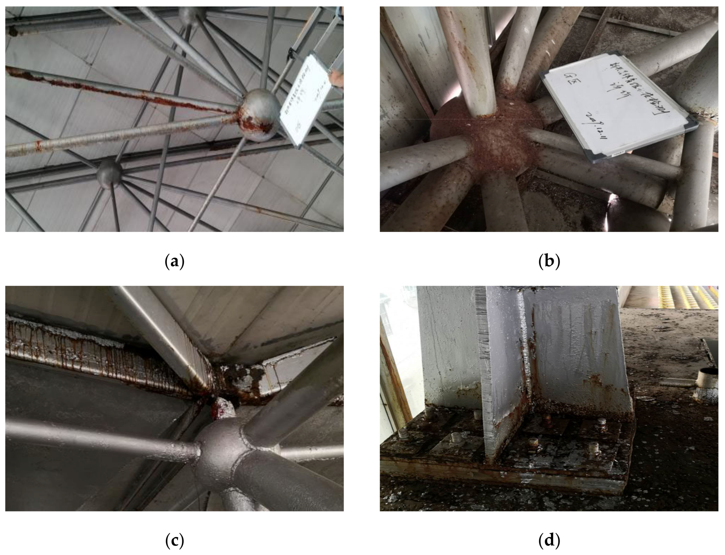
Appearance and Deformation Inspection: As shown in Figure 2, a visual inspection of the appearance and deformation was conducted, which is a qualitative assessment of the structural damage. Minor surface rust was observed on certain cantilever members. Several purlins were completely perforated due to corrosion. Some members and supports exhibited severe rust, though no significant deformation was detected.
(2)
Welded Ball Node Inspection: Ultrasonic testing was conducted on the welds of the spherical nodes in accordance with JG/T 203-2007 [33], revealing multiple weld defects exceeding the permissible limits.
(3)
Support Inspection: Support welds were inspected according to GB/T 26952-2011 [34]. It was found that multiple defects exceeding the permissible limits were identified, with a maximum corrosion depth of 0.8 mm (166.7% above the permissible limit), and several members were fully perforated due to long-term corrosion. The average thickness of the protective coating was measured at 187 μm (standard deviation ± 53 μm), significantly lower than the design specification of 300 μm.
(4)
Steel Cable Testing: The cable forces in the prestressed tendons were measured using the vibration frequency method. The measured cable forces ranged from 525.2 to 545.2 kN, indicating a reduction of 9.1% to 12.5% from the design value of 600 kN. Nonetheless, these values remain within the permissible range defined by the relevant codes.
In summary, the spatial grid structure remained intact and satisfied its basic functional requirements. However, localized damage was concentrated in certain areas, with severe corrosion observed in the support regions and several purlins and members completely perforated. A comprehensive remediation plan was recommended, including damage repair, enhanced corrosion protection, and overall structural reinforcement.

3.3. Retrofitting Plan

The primary objectives of the retrofitting plan were to improve the load-bearing capacity, repair damaged components, and optimize the architectural configuration. The central idea was to balance structural performance restoration with economic feasibility and minimal intervention, preserving as much of the existing structure as possible while enhancing its safety and durability. Based on the results of the damage assessment and functional requirements, the following technical approach was proposed, encompassing three key aspects: damage repair, system reconstruction, and construction control. The appearance and spatial structure of the gymnasium after retrofitting are illustrated in Figure 3.
(1)
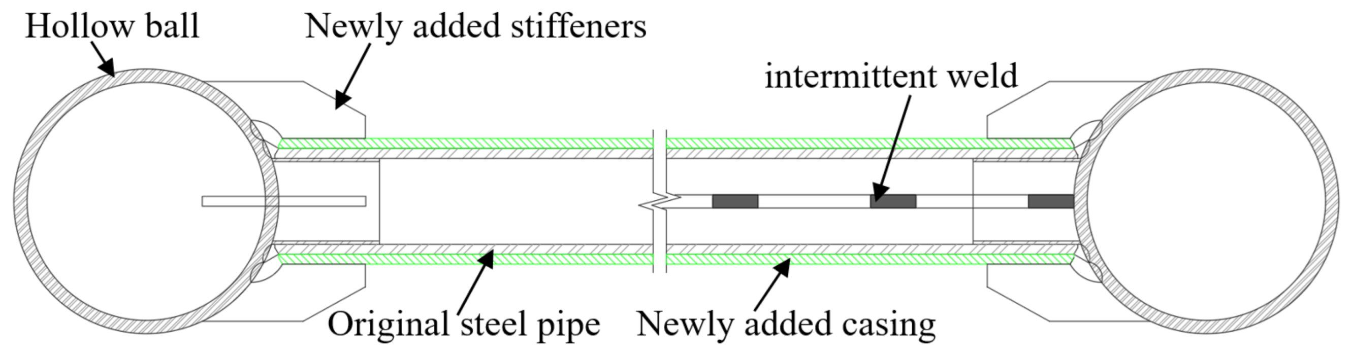
Damage Repair: Based on the inspection results, corroded members were retrofitted using external sleeve reinforcement, as illustrated in Figure 4. To ensure structural safety and maintain adequate safety margins, all damaged members were reinforced using external sleeves. Furthermore, given the structure’s bilateral symmetry, reinforcement schemes were applied symmetrically to achieve balanced load distribution. This method was selected over full member replacement primarily due to the following: the overall structure remaining functionally adequate; the need to minimize disruption to existing load paths; the lower cost and simpler implementation of sleeve reinforcement compared to dismantling and reconstructing core structural members.
(2)
System Reconstruction: The eaves at the four corners were dismantled, and cantilever trusses were installed to suspend the side panels, thereby establishing geometrically controlled boundary conditions. This decision was based on two main considerations: aesthetic improvement of the gymnasium and improvement of structural boundaries.
(3)
Construction Control: Following the principle of symmetrical unloading and synchronous displacement, the dismantling process was divided into several analytical steps, each involving the simultaneous unloading of the upper and lower chord nodes.
Due to the geometric complexity of the spatial grid structure and the challenges associated with its construction, dismantling the corner eaves members constituted a critical phase of the retrofitting process. To ensure the structural stability and safety of the main structure during dismantling, a reliable and practicable dismantling plan must be developed and validated through simulation analysis.

4. Numerical Simulation of the Engineering Case Based on ANSYS

4.1. Element Type Selection

In the ANSYS finite element modeling process, element types are selected in strict accordance with the mechanical properties of the structure and the material constitutive behavior [35,36]. To simulate the uniaxial tension characteristics of the prestressed cables, the LINK10, a three-dimensional two-node truss element, was adopted, with the following key parameter settings. The uniaxial tension mode was activated by setting KEYOPT(2) = 1, enabling an accurate representation of the mechanical relaxation behavior of the cables during unloading. The NLGEOM large deformation option was enabled to capture the geometric nonlinearity during the construction phase. Prestressing was applied using the equivalent initial strain method based on Hooke’s law, with the theoretical expression given by the following:
ε 0 = T E l A l
where T is the initial prestressing force; ε0 is the equivalent initial strain; El is the elastic modulus of the cable; Al is the effective cross-sectional area. The initial prestressing force was directly incorporated into the element constitutive equations by defining the INISTATE parameter within the real constant set.
The grid members were discretized using the BEAM188, a three-dimensional quadratic beam element. This element was based on Timoshenko beam theory and had the following engineering applicability features.
(1)
The cubic shape function incorporating shear deformation was enabled by setting KEYOPT(3) = 2, accurately simulating the bending behavior of members with a span-to-depth ratio of 1:15.
(2)
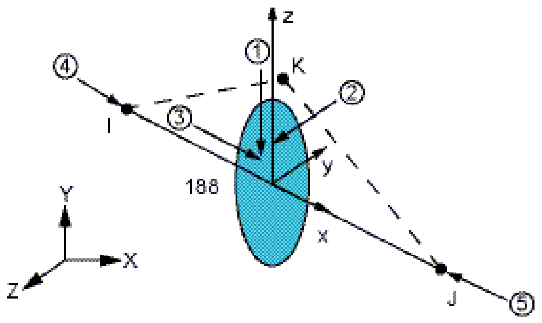
The principal axes of the cross-section were precisely aligned with the global coordinate system via directional node K (as shown in Figure 5).
(3)
It supported the progressive integration algorithm for elastoplastic materials, providing a computational basis for the subsequent strength analysis. Each node included three translational and three rotational degrees of freedom, fully representing the semi-rigid connection characteristics of the grid joints.

4.2. Support Restraint Selection

In the ANSYS finite element numerical simulation, the effectiveness of prestressing depended on the mechanical compatibility between the boundary conditions and the deformation behavior of the structure. Applying full-degree-of-freedom constraints (i.e., fixed supports), rigidly restricted the structural deformations necessary for the release of prestress, thereby impeding the conversion of the prestressing force into internal forces via displacement energy. To enable the effective transfer of prestressing, it was essential to release the corresponding degrees of freedom according to the direction of the prestressing force, thus establishing displacement-compatible boundary conditions. As shown in Figure 6, the overall deformation characteristics of the spatial grid structure induced by prestressing the cable tensioning were analyzed in the gymnasium retrofit project. Accordingly, translational restraints in the Y-direction at supports 1 and 3 and those in the X-direction at supports 2 and 4 were selectively released. This selective release of constraints established a semi-free boundary system, ensuring structural stability while enabling the redistribution of internal forces through controlled displacements driven by the prestressing force.

4.3. Damage Considerations and Material Properties

The structural damage assessment identified a maximum corrosion depth of 0.8 mm in the members. Adopting a conservative assumption, all corroded members were modeled with a uniform thickness loss equivalent to this maximum depth (0.8 mm), resulting in a corresponding reduction in their cross-sectional areas. For material constitutive behavior, Q235 steel was characterized by an idealized bilinear elastoplastic model with the following parameters: elastic modulus 200 GPa, yield strength 235 MPa, and tangent modulus 10 GPa, representing 5% of the elastic modulus.

5. Stability Analysis

5.1. Analysis Method

This study established a numerical simulation framework for analyzing the stability of spatial grid structures using ANSYS finite element software. The method integrated linear eigenvalue buckling analysis with geometric nonlinear post-buckling path-following techniques to systematically identify critical buckling mechanisms and imperfection sensitivity. The analysis process strictly follows the Koiter initial imperfection theory framework [37,38] and comprises the following steps:
(1)
Static Analysis: A static analysis (using ANTYPE = 0 with PSTRES, ON) was conducted to establish the stress field of the structure under design loads, simulating the influence of prestress on buckling behavior. Its mechanical essence lay in the correction of initial stress stiffness matrix in linear elastic stability theory, which provided the baseline stress state for subsequent buckling analysis.
(2)
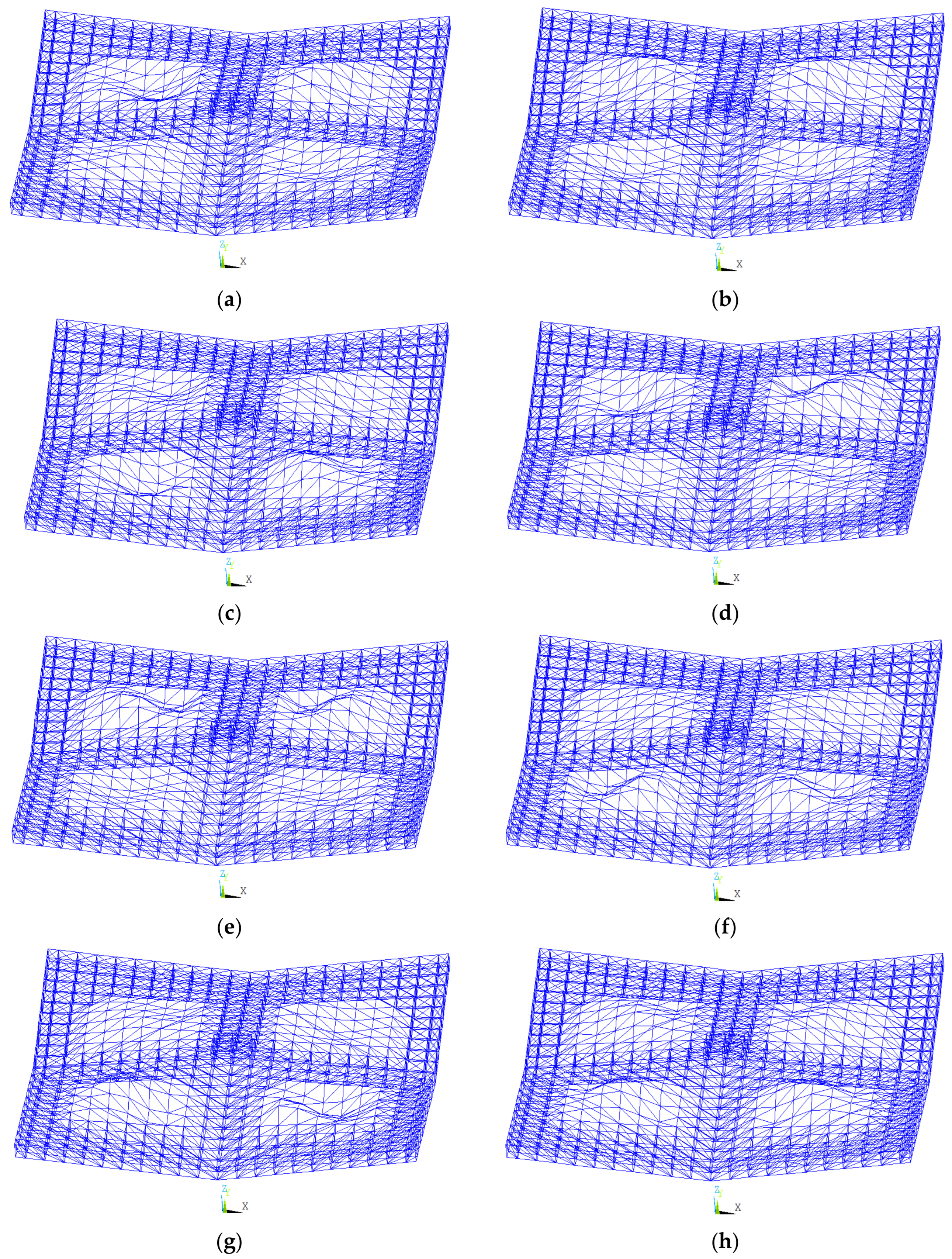
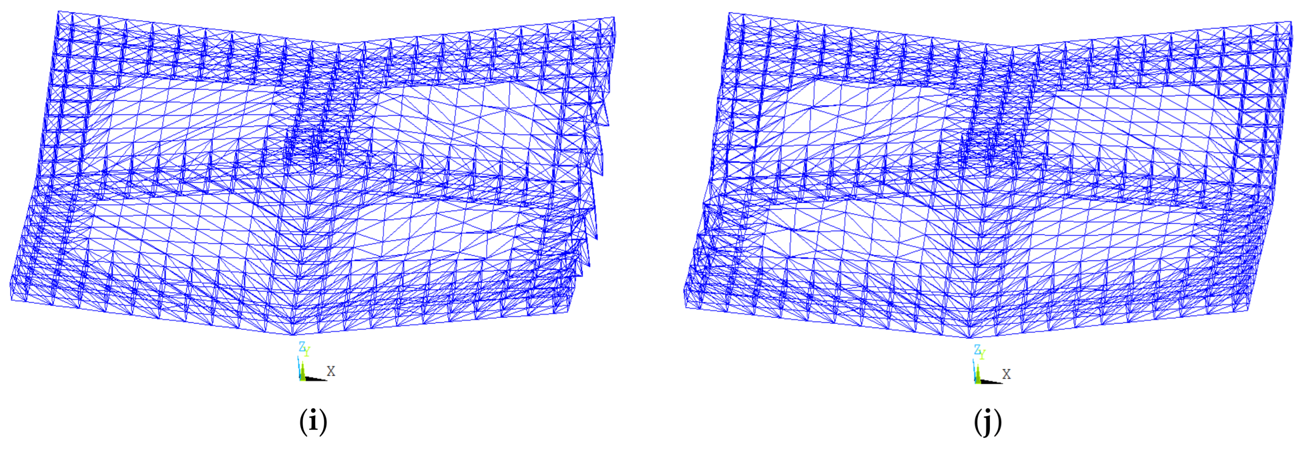
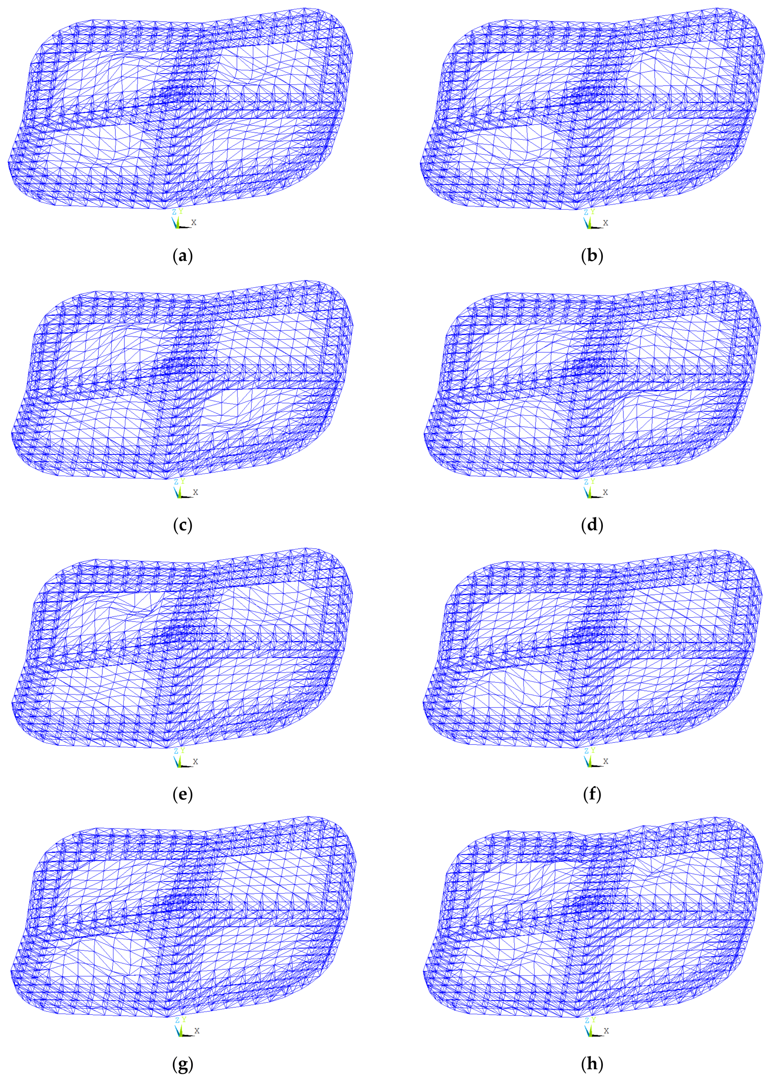
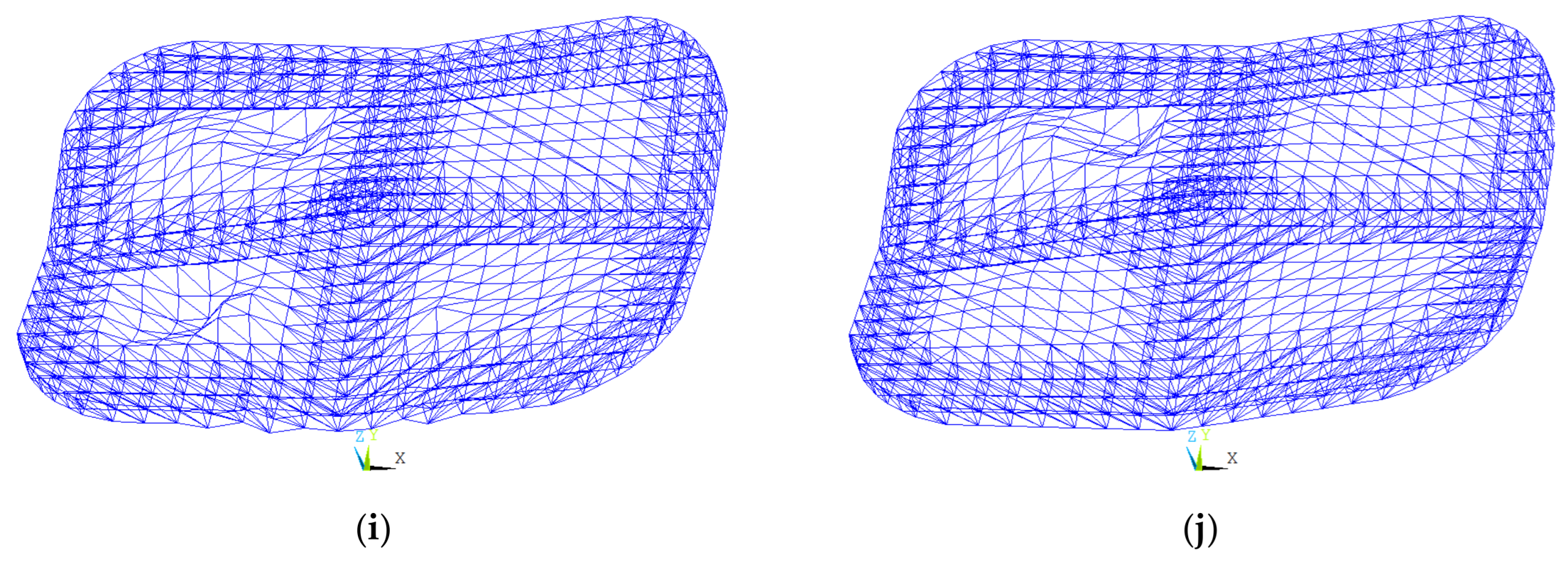
Linear Buckling Analysis: The Block Lanczos algorithm (ANTYPE = 1 with BUCOPT, LANB) was employed to extract the first 10 instability modes and critical load factors. The lowest-order mode eigenvalue represented the theoretical Euler critical load of the ideal structure. The modal shapes were expanded into visible displacement fields using the MXPAND command, providing geometric imperfections for modeling. The obtained linear stability coefficient reflected the theoretical resistance to the instability of a defect-free linearly elastic structure.
(3)
Application of Initial Imperfections: In the full-process analysis of the spatial grid structures, the influence of initial geometric imperfections caused by manufacturing and installation deviations on structural stability must be considered. The consistent modal method was adopted for an imperfection sensitivity analysis, based on a discrete approximation of the defect sensitivity parameter in Koiter’s post-buckling theory. The lowest-order buckling mode was taken as the initial geometric imperfection shape, with the maximum imperfection amplitude limited to 1/300 of the span.
(4)
Geometric Nonlinear Post-Buckling Analysis: The finite strain formulation (NLGEOM = 1) was activated to establish the updated Lagrangian control equations. The arc-length method (ARCLEN command) was employed to trace the load-displacement path. This method automatically adjusted the incremental step size to overcome stiffness singularities, thereby addressing the convergence difficulties of the traditional Newton–Raphson method near turning points. Key nodal displacement responses were recorded using the NSOL command, constructing a normalized load factor-displacement equilibrium path. The actual buckling load was identified at the turning point of the curve. The obtained nonlinear stability coefficient took into account geometric/material nonlinearities and initial imperfections, representing the safety margin against instability for actual structures.

5.2. Stability Analysis of the Engineering Case

Based on the aforementioned analytical method, the instability modes of the spatial grid structure under design loads were calculated for both the original and retrofitted conditions. The structural stability coefficient was evaluated in accordance with the current steel frame stability assessment criteria. The design loads comprised full-span dead live loads.

5.2.1. Structure Before Retrofitting

The first ten instability modes of the spatial grid structure prior to retrofitting were obtained via eigenvalue buckling analysis, as shown in Figure 7. The corresponding linear stability coefficients were 5.16, 5.29, 5.33, 5.38, 5.40, 5.47, 5.49, 5.64, 6.41, and 6.41. The linear stability coefficients for the first eight modes were less than 5.64. These instability modes mainly exhibited global buckling in the four single-layer grid regions, with symmetrically distributed waveforms, as shown in Figure 7a–h. This indicated significant spatial variation in the stiffness distribution of the original structure, with the single-layer grid regions acting as the critical weak zones for global stability. The linear stability coefficients for the ninth and tenth modes were approximately 6.41. These higher-order modes exhibited local–global coupling instability, where edge node buckling coincided with deformation in the single-layer grid, as shown in Figure 7i,j. This highlighted the sensitivity of node configurations to higher-order instability modes. The difference between the first- and higher-order linear stability coefficients was 1.25. The dominance of global buckling suggested that retrofitting should prioritize the enhancement of stiffness in the single-layer grid regions.
To account for geometric and material nonlinearities, an elastoplastic analysis model incorporating initial imperfections was established. The initial imperfections were modeled by scaling the first-order buckling mode derived from the eigenvalue buckling analysis and applying the corresponding nodal displacement eigenvectors. As shown in Figure 8, the nonlinear stability coefficient–displacement curve of the roof truss prior to retrofitting is derived from the load-displacement response. The results indicated that the maximum nonlinear stability coefficient was 1.907, which was 63% lower than the linear critical value, highlighting the significant weakening effect of nonlinearities on the structural load-bearing capacity. A stiffness degradation inflection point appeared after the coefficient exceeded 1.8. This confirmed that the structural failure mode corresponded to global elastoplastic buckling. According to Clause 4.3.4 of JGJ 7-2010 [39], the nonlinear stability coefficient is required to exceed 2.0 to satisfy the stability requirements. The calculated nonlinear stability coefficient was 1.907, which fell 4.65% short of the allowable threshold (2.0), indicating noncompliance with the stability requirements.
Based on the preceding analysis, the instability mechanism of the spatial grid structure prior to retrofitting was primarily attributed to insufficient global stiffness. Local stiffness enhancement may be achieved by reinforcing structural members or increasing the grid density. The buckling of edge nodes in higher-order modes indicated insufficient connection stiffness, which can be mitigated through optimized joint design (e.g., by incorporating stiffeners). The elastoplastic analysis not only verified the necessity of retrofitting but also demonstrated that the limited redundancy of the original structure compromised its load-bearing capacity. This can be addressed by reconfiguring the structural system to improve internal force redistribution, thereby offering a clear strategic direction for retrofit design.

5.2.2. Structure After Retrofitting

The first ten instability modes of the spatial grid structure after retrofitting are illustrated in Figure 9. The corresponding linear stability coefficients were 5.94, 6.07, 6.14, 6.37, 7.02, 7.06, 7.15, 7.21, 7.23, and 7.30. The instability modes from the first to seventh and tenth orders still exhibit global buckling in the single-layer grid regions, as shown in Figure 9a–g,j. However, the eighth and ninth instability modes had undergone a notable transformation. They have evolved from the node-global coupled buckling before retrofitting to modes primarily governed by local node buckling, as shown in Figure 9h–i. This demonstrated that the reconstruction of the edge node system effectively mitigated the coupling effect of global deformation. Notably, the first-order linear stability coefficient increased from 5.16 before retrofitting to 5.94, and the variation of the higher-order coefficients narrowed from 1.26 to 1.36, indicating a marked improvement in the uniformity of the structural stiffness distribution.
An elastoplastic full-process analysis, incorporating initial imperfections, was performed on the spatial grid structure after retrofitting. As shown in Figure 10, the nonlinear stability coefficient-displacement curve of the roof truss prior to retrofitting was derived based on the load-displacement response. The results indicated that the maximum nonlinear stability coefficient of the structure after retrofitting was 2.088, which was 9.5% higher than that prior to retrofitting and complied with the design code requirements. The above analysis demonstrated that the retrofitting project enhanced the bending stiffness of the single-layer grid region by incorporating cantilever trusses and sleeve reinforcement, as evidenced by the significant increase in the first-order nonlinear stability coefficient. More importantly, the shift in higher-order instability modes from global buckling to localized buckling further confirmed the effectiveness of the system-level reconstruction. The nonlinear stability coefficient of the spatial grid structure after retrofitting satisfied the standard, affirming the feasibility and effectiveness of the adopted retrofitting strategy.

6. Analysis of Member-Removal Process

6.1. Analysis Method

This study employed the birth-and-death element method to simulate the progressive removal of members in the spatial grid structure [40,41]. In the ANSYS finite element analysis, this method dynamically activated or deactivated the stiffness matrix of elements to replicate the sequential removal of structural components during construction. The procedure was as follows.
(1)
A complete finite element model of the member system was first established based on the actual structural parameters.
(2)
A multi-load step transient analysis was employed to discretize the removal process into multiple construction steps.
(3)
By controlling the status parameters of the birth-and-death elements at each construction step, member stiffness was progressively reduced until the elements fully disengaged from the structure.
(4)
Finally, the internal force redistribution and displacement field evolution in each step were extracted through post-processing to assess the safety and stability of the construction process.
The simulation primarily evaluated the structural responses in terms of internal forces and deformations. The evaluation of mechanical performance included two aspects.
(1)
Member Strength: According to GB50017-2017 [42], the section strength of circular steel members subjected to combined tension-bending and compression-bending with moments in both principal directions is calculated as follows.
N A n + M x 2 + M y 2 γ m W n f
where N is the design axial compressive force; Mx and My are the design bending moments about the x and y axes, respectively; m is the plastic development coefficient of the circular section; An is the net cross-sectional area; and Wn is the net section modulus (mm3).
(2)
Member Stability: According to GB50017-2017 [42], if a column segment is not subjected to significant transverse forces or concentrated moments, its global stability under biaxial compression and bending is calculated as follows.
N φ x A f + β m x M x γ x W 1 x ( 1 0.8 N / N E x ) f 1.0
N E x = π 2 E A / ( 1.1 λ x 2 )
where φx is the stability coefficient for the axial compression in the moment plane, mx is the equivalent moment coefficient for the compression-bending stability, Mx is the maximum design moment in the calculated member segment, W1x is the gross section modulus about the x-axis for the most compressed fiber, γx is the plastic development coefficient about the x-axis, A is the gross cross-sectional area, and E is the elastic modulus of steel.

6.2. Analysis of Truss Structure During Construction Phase

The retrofitting project first reinforced the overall structure according to the reinforcement plan, followed by the removal of members at the four corner eaves. The removal process followed the principle of symmetrical unloading and synchronous displacement and was divided into multiple analytical steps. The detailed arrangement of the construction process for dismantling the four corner eaves was as follows:
(1)
As shown in Figure 11, the dismantling sequence of the four corner eaves was divided into two steps diagonally, and the dismantling of the two corner eaves in each step was carried out synchronously.
(2)
As shown in Figure 12, the dismantling sequence of nodes at each corner eave was from outside to inside, with a total of 11 steps. Each step involved dismantling the upper and lower chord nodes, with the dismantling sequence being the upper chord node first and then the lower chord node. The dismantling construction steps for each corner node were 22 steps.
(3)
Combining the dismantling sequence of the four corner eaves with the dismantling sequence of the single corner nodes, the total analysis steps were 44.
Due to the limitation of paper length, a certain analysis step was selected as an example for analysis. As shown in Figure 13, the blue dots indicated the removal nodes and their corresponding connected members. This section simulated and analyzed the structural response during this specific construction step. The design loads considered in the simulation included both dead loads and construction live loads.

6.2.1. Force Analysis

The axial force distribution of the spatial grid structure is illustrated in Figure 14. The results revealed that the axial stress distribution of the members during this removal process exhibited significant spatial variability. The maximum tensile and compressive stresses were 81.3 MPa and −62.7 MPa, respectively, and were mainly concentrated in the support regions of the structure. This phenomenon was consistent with theoretical predictions regarding the principal stress-transfer paths in spatial structures. Notably, the maximum tensile stress was only 34.7% of the yield strength of Q235 steel, indicating that the structure maintained a substantial safety margin during the construction phase. In contrast, the stress levels of members in non-support regions remained below 20 MPa, reflecting the effectiveness of the structural system in uniformly distributing applied loads.
The bending moments of the members are illustrated in Figure 15 and Figure 16. The results show that the peak bending moments in the Mx direction (8.00 kN·m) were significantly higher than those in the My direction (0.99 kN·m). The maximum positive moments occurred in the support regions, where a coupling effect with the axial stress distribution was observed, indicating that these regions were subjected to combined stress states during construction. The negative moments observed in the single-layer grid regions reflected localized reverse curvature, a characteristic of geometric nonlinearity that required close attention during construction monitoring.
Strength and stability verifications of the members were conducted in accordance with Equations (2)–(4). The results indicated that the stresses in all members complied with the limit requirements specified in GB50017-2017 [42]. In addition, based on the mechanical behavior revealed by the numerical analysis, the following construction-optimization measures were proposed. First, considering that the maximum stress occurred in the support regions, temporary diagonal supports should be added in the support regions to improve the combined stress state in these areas. Second, considering the possibility of local buckling in single-layer regions, real-time strain monitoring should be implemented in the single-layer grid regions. And emergency reinforcement procedures should be activated if the negative moment exceeds 70% of the design value. This 30% reserve margin prevented premature plastic hinge formation under construction uncertainties, aligning with the and established engineering consensus.
These measures can effectively mitigate construction risks and ensure the structural stability throughout the construction phase.
This study systematically elucidated the mechanical response behavior of the spatial grid structure during the removal process through a numerical simulation, thereby confirming the safety of the established construction sequence. The findings not only offered direct technical support for this engineering case but also provided theoretical guidance for the development of construction control strategies in similar steel structure retrofitting projects. Future studies should further incorporate practical engineering factors, such as joint semi-rigidity and residual welding stresses, to further enhance the predictive accuracy of the numerical model.

6.2.2. Deformation Analysis

Figure 17 depicts the vertical displacement of the spatial grid structure. The results indicated that during the removal process, the vertical deformation of the spatial grid structure exhibited significant spatial non-uniformity. The maximum vertical deformation, measured at 46.3 mm, occurred in the four corner regions of the structure and contrasted sharply with the minimal deformation observed at the geometric center. This distribution pattern revealed a key mechanical mechanism: as the terminal nodes of the primary load transfer paths, the corner regions experienced substantial moment redistribution upon member removal.
According to JGJ7-2010 [39], the allowable deflection limit for spatial grid structures under loading is L/400. The maximum deformation observed during this construction phase was only 26.5% of the code-specified limit. This finding confirmed that the retrofitted structural system possessed adequate stiffness reserves during the construction phase. Based on numerical simulation, this study revealed the spatial distribution characteristics and temporal evolution of truss deformation throughout the steel structure retrofitting process. The results validated the effectiveness of the construction plan in terms of stiffness control, provided new data supporting deformation control theory for existing steel structure retrofitting projects, and demonstrated the applicability of the proposed analytical method to the construction control of similar spatial grid structures.

7. Conclusions

This paper proposed a stability and construction process evaluation method for existing steel structure retrofitting projects based on an ANSYS finite element analysis. This study provided theoretical guidance and methodological support for the safe execution of such retrofitting works, and the proposed technical approach can be extended to the preservation and renewal of historical buildings. The main conclusions were as follows.
(1)
The proposed stability evaluation method systematically verified the overall performance of the retrofitting scheme through a nonlinear time–history analysis and compliance-based code validation.
(2)
The nonlinear finite element model of the roof structure successfully simulated the dynamic construction process. Incorporating the birth-and-death element technique enabled the refined simulation of structural dismantling and modification stages, thereby enhancing the assessment of structural safety and supporting the identification of potential construction risks.
(3)
This method demonstrated the potential of an ANSYS-based simulation approach to support retrofit decision-making in similar spatial structures, thereby reducing the risk of construction-related accidents. The findings supported the functional upgrading and improved safety performance of existing buildings, aligning with the goals of sustainable urban development.
(4)
The proposed analytical framework served as a valuable reference for retrofitting similar spatial structures. The study confirmed the applicability of finite element technology to the construction simulation of existing structures and provided practical insights for updating relevant engineering codes. However, these findings were subject to inherent limitations due to reliance on a single case study. Further validation through additional case studies, experimental verification, and long-term monitoring is therefore essential to enhance the method’s robustness.

Author Contributions

Conceptualization, D.Z.; data curation, Y.S.; formal analysis, X.Z.; funding acquisition, Z.X.; investigation, Y.Q.; methodology, G.M.; project administration, G.M.; resources, Z.X.; software, W.K.; supervision, Z.X.; writing—original draft, W.K. and G.M.; writing—review and editing, W.K. and G.M. All authors have read and agreed to the published version of the manuscript.

Funding

This research was funded by the National Natural Science Foundation of China under Grant No. 12032009, the Guangdong Provincial Key Laboratory of Intelligent Disaster Prevention and Emergency Technologies for Urban Lifeline Engineering under Grant No. 2022B1212010016 (in China), the Natural Science Foundation of Guangdong Province under Grant No. 2024B1515020028 (in China), and the Special Foundation for Scientific and Technological Innovation Strategy of Guangdong Province under Grant No. pdjh2024a137 (in China).

Data Availability Statement

The original data will be available upon requirement.

Conflicts of Interest

Dongming Zhu and Yao Song were employed by China Railway Construction Engineering Group Co., Ltd. Xiaozhou Zou and Yu Qiu were employed by Guangdong Xiangshun Construction Group Co., Ltd. The remaining author declare that the research was conducted in the absence of any commercial or financial relationships that could be construed as a potential conflict of interest.

References

  1. Lan, T.T.; Liu, F. Historical review of the developments of spatial structures in China. J. Int. Assoc. Shell Spat. Struct. 2006, 47, 81–91. [Google Scholar]
  2. Chen, H.P.; Yin, S.W.; Qiao, C.; He, J.; Hu, M.P. Construction effects on the mechanical states of a truss structure. J. Perform. Constr. Facil. 2022, 36, 04021099. [Google Scholar] [CrossRef]
  3. Luo, Y.Z.; Xue, Y. Recent development and engineering practices of space grid structures in China. Int. J. Space Struct. 2024, 39, 36–49. [Google Scholar] [CrossRef]
  4. Ban, H.; Shi, G. A Review of Research on High-Strength Steel Structures. Proc. Inst. Civ. Eng.-Struct. Build. 2018, 171, 625–641. [Google Scholar] [CrossRef]
  5. Tang, H.Y.; Yang, B. Analysis on Collapse Accidents of Two Steel Structural Buildings. Appl. Mech. Mater. 2011, 94, 547–550. [Google Scholar] [CrossRef]
  6. Zhang, Z.; Xu, S.; Wang, H.; Nie, B.; Su, C. Flexural Buckling Behavior of Corroded Hot-Rolled H-Section Steel Beams. Eng. Struct. 2021, 229, 111614. [Google Scholar] [CrossRef]
  7. Di Sarno, L.; Majidian, A.; Karagiannakis, G. The Effect of Atmospheric Corrosion on Steel Structures: A State-of-the-Art and Case-Study. Buildings 2021, 11, 571. [Google Scholar] [CrossRef]
  8. Melchers, R.E. The Effect of Corrosion on the Structural Reliability of Steel Offshore Structures. Corros. Sci. 2005, 47, 2391–2410. [Google Scholar] [CrossRef]
  9. Lin, W.; Taniguchi, N.; Yoda, T.; Hansaka, M.; Satake, S.; Sugino, Y. Renovation of Existing Steel Railway Bridges: Field Test and Numerical Simulation. Adv. Struct. Eng. 2018, 21, 809–823. [Google Scholar] [CrossRef]
  10. Erdem, I.; Peraza, D.B. Challenges in Renovation of Vintage Buildings. J. Perform. Constr. Facil. 2015, 29, 04014166. [Google Scholar] [CrossRef]
  11. Hooper, J.D. Evaluating and Upgrading Welded Steel Moment-Frame Buildings Using FEMA-351. Earthq. Spectra 2003, 19, 317–334. [Google Scholar] [CrossRef]
  12. Torres, M.A.; Ruiz, S.E. Structural Reliability Evaluation Considering Capacity Degradation Over Time. Eng. Struct. 2007, 29, 2183–2192. [Google Scholar] [CrossRef]
  13. Kukla, D.; Kozłowski, A. Analysis of Steel Frame Under Selected Accidental Situation. Arch. Civ. Eng. 2022, 68, 293–309. [Google Scholar] [CrossRef]
  14. Ma, W.T.; Wang, J.Q.; Chai, Y.L. Adding Layer of Steel Structure of Safety Testing and Add Layer and Reinforcement of Feasibility Analysis. Adv. Mater. Res. 2013, 788, 530–533. [Google Scholar] [CrossRef]
  15. Zhang, Z.J.; Chen, B.S.; Bai, R.; Liu, Y.P. Non-Linear Behavior and Design of Steel Structures: Review and Outlook. Buildings 2023, 13, 2111. [Google Scholar] [CrossRef]
  16. Quan, C.; Walport, F.; Gardner, L. Equivalent Imperfections for the Out-of-Plane Stability Design of Steel Beams by Second-Order Inelastic Analysis. Eng. Struct. 2022, 251, 113481. [Google Scholar] [CrossRef]
  17. Kala, Z. Stability Problems of Steel Structures in the Presence of Stochastic and Fuzzy Uncertainty. Thin-Walled Struct. 2007, 45, 861–865. [Google Scholar] [CrossRef]
  18. Kassimali, A.; Abbasnia, R. Large Deformation Analysis of Elastic Space Frames. J. Struct. Eng. 1991, 117, 2069–2087. [Google Scholar] [CrossRef]
  19. Orbison, J.G.; McGuire, W.; Abel, J.F. Yield Surface Applications in Nonlinear Steel Frame Analysis. Comput. Methods Appl. Mech. Eng. 2006, 33, 557–573. [Google Scholar] [CrossRef]
  20. Liew, J.R.; Chen, H.; Shanmugam, N.E.; Chen, W.F. Improved Nonlinear Plastic Hinge Analysis of Space Frame Structures. Eng. Struct. 2000, 22, 1324–1338. [Google Scholar] [CrossRef]
  21. Liang, B. Detection and Reinforcement of Existing Steel Bridges Research. Master’s Thesis, Hebei University of Technology, Tianjin, China, 2014. [Google Scholar]
  22. Chen, R.; Zhang, K.; Zhou, F.; Zhang, X.; Shan, Y. Engineering Applications of Prestressing Technique in Strengthening Steel Structure. Build. Struct. 2019, 49, 934–937. [Google Scholar]
  23. Zhao, X.H. Investigation on Safety Assessment and Strengthening Method of Gas Station Double Layer Grids. Master’s Thesis, Harbin Institute of Technology, Harbin, China, 2018. [Google Scholar]
  24. Luo, L.S.; Luo, Y.F.; Guo, X.N. Analysis Method for Safety Assessment of Existing Steel Structure Member. J. Hunan Univ. Nat. Sci. 2014, 41, 20–25. [Google Scholar]
  25. Wang, X.L.; Feng, Z.J.; Ren, G.L. Simulation Analysis of Steel Structure Construction Process of Large Complex Gymnasium. J. Beijing Jiaotong Univ. 2020, 44, 17–24. [Google Scholar]
  26. Parisi, F.; Ruggieri, S.; Lovreglio, R.; Fanti, M.P.; Uva, G. On the Use of Mechanics-Informed Models to Structural Engineering Systems: Application of Graph Neural Networks for Structural Analysis. Structures 2024, 59, 105712. [Google Scholar] [CrossRef]
  27. Nishimura, S.; Tatsuki, S.; Kobayashi, M.; Siringoringo, D.M.; Maekawa, K.; Fujino, Y. Seismic-induced damage and restoration of rigid-frame reinforced concrete abutments for high-speed trains. Eng. Struct. 2025, 327, 119598. [Google Scholar] [CrossRef]
  28. Yao, G.; Li, R.; Yang, Y.; Cai, X.; Zhou, Y.; Zhou, C.; Lei, T. Analysis of Mechanical Properties during Construction Stages Reflecting the Construction Sequence for Long-Span Spatial Steel Structures. Buildings 2024, 14, 2389. [Google Scholar] [CrossRef]
  29. Yosefi, A.; Mojtahedi, F.F.; Bahrami, M. Identification of Damages in Concrete and Steel Structures: A Comprehensive Review. In Damage Detection and Structural Health Monitoring of Concrete and Masonry Structures; Springer: Singapore, 2025; pp. 207–247. [Google Scholar]
  30. Hait, P.; Sil, A.; Choudhury, S. Overview of Damage Assessment of Structures. Curr. Sci. 2019, 117, 64–70. [Google Scholar] [CrossRef]
  31. GB50009-2012; Load Code for the Design of Building Structures. Ministry of Housing and Urban-Rural Development of the People’s Republic of China: Beijing, China, 2012.
  32. GB/T 50621-2010; Technical Standard for In-Site Testing of Steel Structure. Ministry of Housing and Urban-Rural Development of the People’s Republic of China: Beijing, China, 2010.
  33. JG/T 203-2007; Method for Ultrasonic Testing and Classification for Steel Structures. Ministry of Construction of the People’s Republic of China: Beijing, China, 2007.
  34. GB/T 26952-2011; Non-Destructive Testing of Welds—Magnetic Particle Testing of Welds—Acceptance Levels. General Administration of Quality Supervision, Inspection and Quarantine of the People’s Republic of China: Beijing, China, 2011.
  35. Abambres, M.; Arruda, M.R. Finite Element Analysis of Steel Structures—A Review of Useful Guidelines. Int. J. Struct. Integr. 2016, 7, 490–515. [Google Scholar] [CrossRef]
  36. Wang, L.; Liu, B.S.; Yang, N. Nonlinear Finite Element Analysis on the Steel Frame with Semi-Rigid Connection Under Periodic Load. Adv. Mater. Res. 2011, 255, 614–618. [Google Scholar] [CrossRef]
  37. Kornilov, T.; Kychkin, I.; Nazarov, T.; Nikiforov, A. Light-Gauge Frame Construction: Numerical Analysis and Research. IOP Conf. Ser. Mater. Sci. Eng. 2018, 456, 012020. [Google Scholar] [CrossRef]
  38. Hu, S.J. Stability Analysis of Roof Structure with Steel Tubular Arch-Truss. Adv. Mater. Res. 2011, 255, 587–590. [Google Scholar] [CrossRef]
  39. JGJ7-2010; Technical Specification for Space Frame Structures. Ministry of Housing and Urban-Rural Development of the People’s Republic of China: Beijing, China, 2010.
  40. Zheng, S.; Chen, X. Study on Construction Technique of Complex Multi-Layer Steel Structure. Adv. Mater. Res. 2012, 430, 1009–1013. [Google Scholar] [CrossRef]
  41. Guo, Y.; Zhang, Q.; Bai, X.Q.; Pan, S.H. The Deformation Analysis and Control of Large Steel Structures Based on Non-Slide Construction Site. Adv. Mater. Res. 2011, 255, 649–653. [Google Scholar] [CrossRef]
  42. GB50017-2017; Standard for Design of Steel Structures. Ministry of Housing and Urban-Rural Development of the People’s Republic of China: Beijing, China, 2017.
Figure 1. The appearance and spatial structure of the gymnasium. (a) Appearance; (b) spatial structure.
Buildings 15 02059 g001
Figure 2. Visual inspection of surface condition and deformation. (a) Corrosion of rod members; (b) corrosion at welded joints; (c) corrosion of purlins; (d) corrosion of supports.
Buildings 15 02059 g002
Figure 3. The appearance and spatial structure of the gymnasium after retrofitting. (a) Appearance; (b) spatial structure.
Buildings 15 02059 g003
Figure 4. Casing reinforcement method.
Buildings 15 02059 g004
Figure 5. BEAM188 element schematic.
Buildings 15 02059 g005
Figure 6. Position and number of supports for the model.
Buildings 15 02059 g006
Figure 7. First ten instability modes before retrofitting. (a) First-order buckling mode; (b) second-order buckling mode; (c) third-order buckling mode; (d) fourth-order buckling mode; (e) fifth-order buckling mode; (f) sixth-order buckling mode; (g) seventh-order buckling mode; (h) eighth-order buckling mode; (i) ninth-order buckling mode; (j) tenth-order buckling mode.
Buildings 15 02059 g007aBuildings 15 02059 g007b
Figure 8. Nonlinear stability coefficient-displacement curve before retrofitting.
Buildings 15 02059 g008
Figure 9. First ten instability modes after retrofitting. (a) First-order buckling mode; (b) second-order buckling mode; (c) third-order buckling mode; (d) fourth-order buckling mode; (e) fifth-order buckling mode; (f) sixth-order buckling mode; (g) seventh-order buckling mode; (h) eighth-order buckling mode; (i) ninth-order buckling mode; (j) tenth-order buckling mode.
Buildings 15 02059 g009aBuildings 15 02059 g009b
Figure 10. Nonlinear stability coefficient-displacement curve after retrofitting.
Buildings 15 02059 g010
Figure 11. Dismantling sequence of four corner eaves.
Buildings 15 02059 g011
Figure 12. Dismantling sequence of single corner nodes.
Buildings 15 02059 g012
Figure 13. Locations of demolition nodes in the construction analysis step.
Buildings 15 02059 g013
Figure 14. Axial stress distribution of members. (a) Axial stress (Pa); (b) axial force (N).
Buildings 15 02059 g014
Figure 15. Bending moments of members in Mx direction (N·m). (a) Mx at one end; (b) Mx at the other end.
Buildings 15 02059 g015
Figure 16. Bending moments of members in My direction (N·m). (a) My at one end; (b) My at the other end.
Buildings 15 02059 g016
Figure 17. Vertical deformation of spatial grid structure (m).
Buildings 15 02059 g017
Table 1. Statistics of cross-sectional parameters of members before retrofitting.
Section NumberOuter Diameter (mm)Thickness (mm)Cross-Sectional Area (mm2)Turning Radius (mm)Width-to-Thickness Ratio
1753.758392520
24834241616
36035372020
4180738046125.71
5159524195531.8
6127415464431.75
7114413823928.5
889410683022.25
9219746627531.29
10140417094835
Table 2. Statistics of cross-sectional parameters of members after retrofitting.
Section NumberOuter Diameter (mm)Thickness (mm)Cross-Sectional Area (mm2)Turning Radius (mm)Width-to-Thickness Ratio
1753.758392520
26035372020
34834241616
41591255425213.25
5180738046125.71
6159524195531.8
7127415464431.75
8114413823928.5
989410683022.25
10140417094835
111801263335915
12168525605833.6
13219746627531.14
Disclaimer/Publisher’s Note: The statements, opinions and data contained in all publications are solely those of the individual author(s) and contributor(s) and not of MDPI and/or the editor(s). MDPI and/or the editor(s) disclaim responsibility for any injury to people or property resulting from any ideas, methods, instructions or products referred to in the content.

