Article

Upper Shallow Foundation Pit Engineering: Utilization and Evaluation of Portal Frame Anti-Heave Structures

1
School of Civil and Environmental Engineering, Harbin Institute of Technology (Shenzhen), Shenzhen 518055, China
2
Shenzhen Metro Group Co., Ltd., Shenzhen 518026, China
3
College of Civil and Transportation Engineering, Shenzhen University, Shenzhen 518060, China
4
School of Civil Engineering, Inner Mongolia University of Science and Technology, Baotou 014010, China
*
Author to whom correspondence should be addressed.
Buildings 2025, 15(11), 1943; https://doi.org/10.3390/buildings15111943
Submission received: 19 April 2025 / Revised: 28 May 2025 / Accepted: 1 June 2025 / Published: 4 June 2025
(This article belongs to the Special Issue Design, Construction and Maintenance of Underground Structures)

Abstract

The excavation of upper shallow foundation pits may cause the uneven deformation of existing tunnels buried below a shallow depth. Improper control measures may lead to a series of diseases, such as local cracking or breakage of the tunnel lining, which threaten the safety of tunnel operations. Regarding the safety of the existing tunnel affected by the construction of the foundation pit, cases of the application of portal frame anti-heave structures in upper foundation pit projects of existing tunnels in Shenzhen have been documented, and the main influencing factors have been analyzed and summarized. Taking the Qianhai Ring Water Corridor Project as an example, numerical orthogonal experiments were conducted to analyze the deformation response patterns in the depth of existing tunnels and the effectiveness of control measures in the upper shallow of foundation pit engineering. The roles of portal frame anti-heave structures are analyzed in detail using measured data. Studies indicate that the deformation of the existing tunnels mainly occurs during the top and immediately adjacent block excavation stages, and stabilizes after the uplift-resisting piles and anti-floating slabs form an effective frame structure. The portal frame anti-heave structures, combined with measures such as block excavation, jet grouting interlocking reinforcement, backfilling, and surcharge loading, have extremely strong deformation control capabilities. However, the construction costs are relatively high, leaving room for optimization.

1. Introduction

As the intensity of urban underground space development gradually rises and new types of underground projects such as urban underground roads and underground complexes emerge in large numbers, foundation pit projects located on either side or above existing tunnels are gradually increasing. The construction of this type of foundation pit project is likely to cause significant disturbances to the surrounding stratum, which in turn will affect the structure of existing tunnel in the stratum through the coordinated action of stratum-structure deformation. In serious cases, it will cause local cracking and damage to the tunnel segments, track distortion, track bed disconnection, pantograph arcing, and other diseases, seriously threatening the security of tunnel operation [1,2,3]. In this case, the major factors to be taken into account in the planning and construction of the foundation pit project are not only the stability of the self-supporting system, but also the impact on surrounding existing tunnels and other existing buildings and structures.
In the practice of constructing new shield tunnels beneath existing ones, there are many relevant cases. Most of them carry out research through conventional technical means such as slurry support and face stability control [4,5,6]. In contrast, the portal frame anti-heave structure is a relatively new approach. Scholars have conducted some research on the mechanisms of the deformation of existing tunnels resulting from the excavation of the upper foundation pit and the control technologies, etc. Liu et al. [7] simplified the existing tunnel into an elastic beam on the Pasternak foundation. They first calculated the vertical unloading stress resulting from the excavation of the upper foundation pit and related dewatering at the location of the existing tunnel, and then calculated the vertical deformation of the tunnel based on this. This method has been verified in the Chegongmiao Hub Project in Shenzhen and can produce quick and precise evaluation conclusions for comparable projects. Zhang et al. [8], through the method of combining field experiments and computer simulations, used the viscoelastic viscoplastic strain softening (VEVP-SS) constitutive model to precisely describe the relationship between stress and strain of the cohesive flysch geotechnical materials, and studied the deformation response of tunnel excavation in cohesive strata. It was found that, compared with the classical creep model, the VEVP-SS model can more accurately simulate the vertical displacement caused by creep during the excavation process. Ng et al. [9] studied the influence of foundation pit excavation in dry sand on existing tunnels through three-dimensional centrifuge model tests. They observed and assessed the deformation of the tunnels during the simulated foundation pit excavation process, providing an experimental basis for understanding the interacting mechanism between the foundation pit and the tunnel in sandy soil. In the relevant engineering practices in London, it was found that the excavation of a 12-m-deep foundation pit led to a 60-mm uplift of the nearby tunnel. Moreover, because of the clay layer’s gradual and prolonged consolidation, the uplift is still continuing, which indicates that the long-term soil consolidation effect is an important factor causing the deformation of the tunnel resulting from the foundation pit excavation. Schweiger et al. [10], as well as Komiya et al. [11], believed that grouting consists of two stages: compaction grouting and fracture grouting. El-Kelesh et al. [12] proposed a model of theory for compressed grouting based on the theory of cavitation expansion and the theory of shear failure with a tapered shape above the grouting pack, which explained how the compaction grouting process works. Cai et al. [13] carried out numerical research on the uplift of existing tunnels during the construction of new tunnels through numerical simulation, analyzed the deformation rules of the tunnels based on diverse construction parameters and geological conditions, and provided a basis for optimizing the construction scheme. Pang et al. [14] carried out three-dimensional computer parametric research to analyze various factors affecting the existing tunnels caused by foundation pit excavation, such as the size of the foundation pit, the excavation depth, the burial depth of the tunnel, etc. With the approach of computer simulation, they obtained the laws of the influence of each factor on the deformation on the tunnel, producing a reference for engineering design and construction.
Shenzhen has complex geological conditions, abundant groundwater, and a small urban area, making it an area with a high degree of underground space development and a heavy metro protection task. In recent years, uplift-resistant piles and anti-floating slabs combined portal frame anti-heave structures have been used in small quantities in deep or shallow foundation pit projects, with good results [15,16,17]. However, considering that the portal frame structures can only be put into effect after the excavation of the corresponding blocks is complete and the pile plate structures form a whole, and that the project costs and time costs are high, it is worth further research on the optimization of the existing tunnel deformation control measures for projects with shallow foundation pits.
Due to the conditions of underground engineering and the complexity of the portal frame structures, a simple theoretical analysis can no longer meet the requirements of structural deformation response and mechanism analysis. This paper will conduct an in-depth study of the deformation response of existing tunnels and the control effect of portal frame structures under different control measures based on a statistical analysis of existing engineering cases, the establishment of a detailed model in the context of actual projects, and the implementation of a numerical orthogonal experiment combined with on-site measurements.

2. Case Study on the Application of Portal Frame Anti-Heave Structures

Regarding the design and application of portal frame anti-heave structures, this paper analyzes 10 engineering cases in the Shenzhen area that have adopted portal frame anti-heave measures since 2014. These cases are scattered in major urban areas such as Luohu, Futian, Nanshan, and Bao’an, and cover engineering types such as water corridors, underground expressways, large building foundation pits, airport runways, and bridge foundation platforms, which are quite representative. From these cases, fifteen typical cross-sections are selected, mainly involving major factors such as stratum parameters, deformation control measures for existing tunnels, foundation pit unloading ratio, uplift-resisting pile design parameters, and anti-floating slab design parameters. The design parameters of portal frame anti-heave structures for typical cross-sections are detailed in Table 1. Among them, the typical cross-section design parameters of the project on which this paper is based are shown in Table 1 No. 15.

2.1. Stratum Parameters

It can be seen from the stratum parameters that a residual soil layer of a certain thickness exists around the majority of the existing tunnels in the case project, indicating that the residual soil layer is widely distributed in the Shenzhen area. At the same time, the characteristics of residual soil, which are strong structure, susceptibility to disturbance, and ease of disintegration, are factors that need to be taken into account when formulating subway protection measures.

2.2. Deformation Control Measures for Existing Tunnels

In terms of anti-heave control measures, in addition to using portal frame structures and stepwise excavation, one or more of the following measures are often used in combination according to the actual projects: ground stratum reinforcement, vertical wells, and surcharge. Specifically, the range of ground reinforcement includes the main types of upper rectangle, portal, etc. Shafts are divided into two main types, which are continuous and discontinuous, and the width of the shaft is basically controlled at about 6.0 m. The portal frame anti-heave structure includes uplift-resisting piles and anti-floating slabs, and the uplift-resisting piles are mainly cast-in situ piles, and cement-mixed piles are applied in some projects, and the piles are arranged in three or four rows according to the situation. Anti-floating slabs are divided into two types: those that are separate from the foundation pit floor and those that are shared, and when a shaft is used, a separate arrangement is usually used.

2.3. Foundation Pit Unloading Ratio

In the typical cross-section of the statistics, there is a wide range of existing tunnel depths, with the main distribution range being 8.5 to 22.5 m. Under the conditions of a water-rich weak stratum, the depth of a deeply buried tunnel is generally located at 2.5D to 3.0D, where D represents tunnel diameter. It can be seen that most of the existing tunnels in the cross-section are shallowly buried. The main distribution range of the foundation pit depth is 4.0 to 19.0 m, and the main distribution range of the unloaded ratio calculated is 0.4 to 0.8. The existing tunnel structure will undergo corresponding deformation as the foundation pit is excavated.

2.4. Uplift-Resisting Pile Parameters

Providing sufficient uplift resistance through the friction between the uplift-resisting piles and the stratum is the key to the portal frame structure’s ability to restrain stratum deformation, and a reasonable pile length and diameter can effectively improve uplift resistance and reduce project costs. The main considerations for pile length and diameter design are the surrounding stratum conditions of the tunnel and the influence range of the foundation pit excavation. From a statistical point of view, the pile length is generally set to be 6 to 12 m below the bottom of the tunnel, which is about one to two times the diameter of the tunnel. The main pile diameters are 1.0 and 1.2 m. A pile diameter exceeding 1.2 m will result in a significant increase in piling cost. A pile diameter of less than 1.0 m will provide significantly less friction resistance, but the cost reduction will be limited.

2.5. Anti-Floating Slab Parameters

Anti-floating slabs are mainly divided into two types: those that are shared with the upper structures and those that are separate. When anti-floating slabs are shared with the upper structures, their thickness mainly relies on the load-bearing demands of the upper frameworks. When separated from the upper structures, anti-floating slab thickness is not more than 1.0 m, mostly located in the range of 0.6 to 0.8 m. At this time, the main adverse loads of anti-floating slabs are the uplift force and backfilling and surcharge loading transmitted by the stratum in the course of construction, which is not much for the load carrying capacity requirements.

3. Numerical Orthogonal Experimental Scheme

In summary, considering the multiple influences of upper pit construction on the structural deformation of existing tunnels and the complexity of the influence mechanism of upper pit construction, a multi-factor and multi-level systematic study is required for the purpose of revealing the deformation response of existing tunnels under different combinations of control measures. The factors involved in the project are complicated and variable, and the theoretical analysis, model test, and other research means are obviously limited, so it is a reasonable and effective way to carry out a series of numerical experiments on the basis of obtaining accurate stratum and structural parameters, and through the orthogonal experiment planning approach, it is possible to achieve the optimal selection of aspects, the impact analysis, and other experimental purposes with a notable decrease in the quantity of experimental groups.

3.1. Constitutive Model

The selection of the soil constitutive model plays a crucial part in improving the rationality and accuracy of numerical analysis. A significant quantity of engineering field test results demonstrate that the stiffness of the soil displays more pronounced nonlinear deformation features as the strain of the soil grows, and except for a small part of the ground surrounding the foundation pit and tunnel structure that undergoes plastic deformation, the order of magnitude is generally 0.01% to 0.1% [18,19,20]. Therefore, in numerical analysis, only by taking into account the soil’s small-strain stiffness properties, in particular its high modulus and high nonlinearity under small-strain conditions, can the deformation of ground or tunnels resulting from foundation pit excavation be more reasonably predicted.
In this paper, FLAC3D 6.0, a finite difference software, and a plastic-hardening model are used to carry out numerical orthogonal experiments. This model considers the shear and compression hardening of soil, as well as the attenuation of shear modulus in the small strain range as shear strain increases. It can accurately describe the destruction and deformation behavior of various types of soil and is more suitable for impact analysis of foundation pit excavation in complex environments.

3.2. Case Project Overview

Numerical orthogonal experiments are carried out with the background of the ring water corridor project to overpass the existing Metro Line 9 in the Qianhai Shenzhen-Hong Kong Cooperation Zone. The tunnel intersects the axis of the water corridor at an angle of 85°. The top line of excavation ranges from 46.0 m in length and 31.2 m in width, with a depth of 5.0 m to 5.5 m, and the clear distance between the tunnel pits is 3.0 m, the unloading ratio is about 0.65, and the excavation adopts sloping, with a slope of 1:0.5. The depth of the existing tunnel is 8.0 m, and the external diameter of the existing shield tunnel lining is 6.0 m. The width of the tube sheet is 1.5 m, the thickness of the tube sheet is 0.3 m, and the strength of the concrete is C50, with a clear distance between the left and right lines of 7.8 m. The main channel of the water corridor has a clear width of 20.0 m and a clear height of 4.0 m. The length of the bottom plate is 39.0 m, the width is 24.2 m, and the thickness is 1.0 m. Three rows of uplift-resisting piles are set up along the two sides of the existing tunnel with a pile diameter of 1.2 m and a length of 22.0 m, of which there are seven piles on the side, with the center spacing of 3.0 m, and 10 piles in the middle, with the center spacing of 2.0 m, and the thickness of the side wall is 0.8 m, and the foundation pit profiles are shown in Figure 1 and Figure 2.

3.3. Model Parameters

The model is 160 m in length, 140 m in width, and 50 m in height. The overall model is shown in Figure 3, and the connection between the portal frame structure and the tunnel location is depicted in Figure 4.
According to the in situ wave velocity test and the on-site geological survey, the stratum is generally divided into six layers, which are fill soil, fill stone, cohesive soil, sandy cohesive soil or remnant soil, fully weathered granite, and strongly weathered granite. The parameters of the stratum pH model are determined by combining the results of indoor experiments and referring to relevant studies on similar sites [21,22], as shown in Table 2 in detail.
In order to accurately simulate the deformation characteristics of the existing tunnel and to consider the weakening effect of the inter-ring and intra-ring bolts on the tunnel lining’s rigidity, a modeling method of standard rings and bolt rings is adopted. The bolt ring width is 0.4 m, the standard ring is 1.1 m, the transverse stiffness coefficient of the tunnel structure is 0.7, and the bolt ring stiffness weakening factor is 0.4 [23]. The anti-floating slabs are 1.0 m thick and C35 in strength, and the uplift-resisting piles are 1.2 m in diameter and C40 in strength. The cross-section stiffness parameters are all set using the EA equivalence principle. The strata are reinforced by using high-pressure double-pipe jet grouting interlocking piles and the size of these piles is ϕ800@600, which can be regarded as uniform full-section reinforcement. The plane of the reinforced area extends 2 m beyond the top line of excavation, and the vertical reinforcement range is adjusted according to different working conditions. The strata involved in the reinforcement are fill soil, fill stone, and sandy cohesive soil. With reference to relevant experience and research results on jet grouting reinforcement [24], the strength of the reinforced stratum is more than 1.5 MPa, the permeability coefficient is 1 × 10⁻⁶ cm/s, the soil in the reinforced area adopts the pH model, the relevant indicators of stiffness are increased 2 times, c is increased 10 times, and ϕ is increased by 1.5 times, while other indicators remain unchanged.

3.4. Construction Process Simulation

The numerical model is in the fluid-structure interaction calculation mode. The groundwater normal level of water is minus 2.0 m, and the precipitation is 2.0 m beneath the foundation pit’s bottom. The main construction steps include: initial ground stress balance. precipitation. stratum reinforcement. pouring of uplift-resisting piles. block-by-block, layered excavation. installation of anti-floating slabs. load application.

3.5. Orthogonal Experimental Scheme

The evaluation indicators selected for this test are the maximum vertical deformation of the vault and the horizontal deformation of the central axis during the construction process. Since the existing tunnel construction and the deformation during the preliminary operation stage are not considered, the index values are all increments during the foundation pit construction process.
For the purpose of effectively controlling the deformation of existing tunnels, a combination of control measures is usually adopted, mainly including step excavation, surcharge loading, stratum reinforcement, external anti-uplift structures, etc. These measures differ in their mechanisms of action and primary targets, and the effectiveness of their implementation also differs under different engineering conditions. Combining the experience of implementing the upper foundation pit of the existing tunnels in Shenzhen and other areas, and relying on the actual situation of the project, the four factors of zone group factor as the scope of reinforcement, uplift-resisting pile length, excavation method, and backfilling and surcharge loading are selected. Among them, factors 1 to 3 are set at four levels. Considering the excavation depth is 5 m and the subdivision of the load value is not significant, factor 4 is set at two levels, as shown in Table 3 in detail.
The reinforcement scope and excavation methods are shown in Figure 5 and Figure 6.
According to the level setting of the block factor, choose the L16 (44) orthogonal table. Among them, Factor 4 has only two levels. According to the proposed level method, levels 3 and 4 are replaced by levels 1 and 2, respectively. Substituting each level value of factors into the orthogonal table gives the specific operating conditions for each group of tests, as shown in Table 4.

4. Deformation Response of Existing Tunnels

This paper only analyzes the response of the vertical deformation of the tunnel vault and the horizontal deformation of the central axis, taking the average of the horizontal deformation of the two arch waists. The tunnel deformation is only the structural deformation caused by the construction of the upper foundation pit.

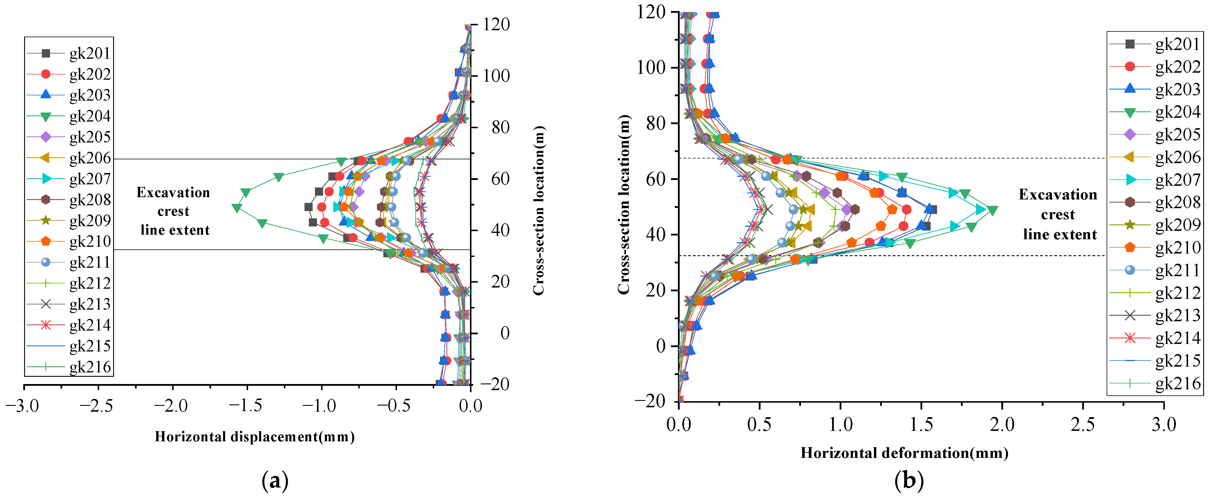
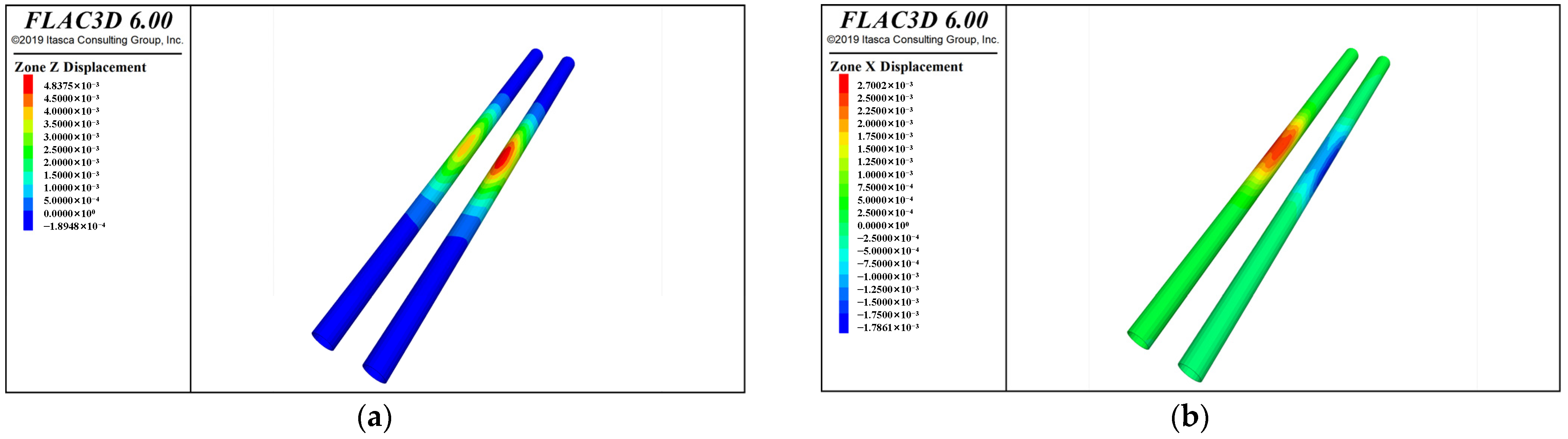
4.1. Tunnel Deformation Distribution

The vertical deformation of the existing tunnel vault and the horizontal deformation of the axis at the end of the construction of the foundation pit under each working condition are shown in Figure 7 and Figure 8, respectively. The deformation distribution cloud pictures for the corresponding working conditions when the vertical deformation of the vault and the maximum horizontal deformation of the axis are the largest are shown in Figure 9 and Figure 10, respectively.
From Figure 7, Figure 8, Figure 9 and Figure 10, it can be seen that:
(1) Along the longitudinal axis of the existing tunnel, both the vertical deformation of the vault and the horizontal deformation of the central axis show a roughly normal distribution with obvious peaks, situated close to the centerline of the water corridor’s foundation pit.
(2) Due to the combined impact of multiple aspects, there is a distinction between the extreme values of left and right line deformation. Among them, the distinction in vertical deformation of the left and right line vaults is the largest under the overall half-excavation method, and the maximum vertical deformation appears in the left line tunnel of working condition 207, with a maximum value of 4.66 mm. Conversely, the horizontal deformation of the right tunnel line, which has a relatively late unloading of the upper soil, is generally more obvious than that of the left line, and the maximum horizontal deformation occurs in the right line tunnel of working condition 204, with a maximum value of 1.94 mm, which is a lot less than the maximum vertical deformation, confirming vertical deformation as the main control index of deformation.
(3) The scope of foundation pit excavation’s impact, when the tunnel deformation is more than 0.25 mm, is about 10 m beyond the top line of excavation, which is twice the excavation depth. The influence range is mainly related to the depth and total width of the foundation pit excavation and is less affected by the four zone group factors of the test design.

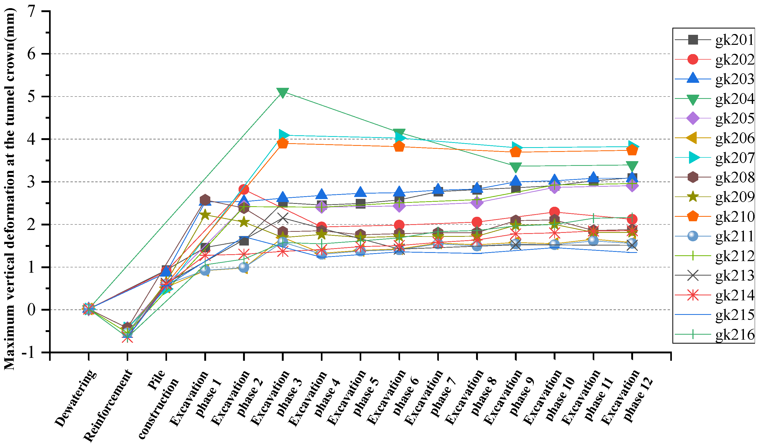
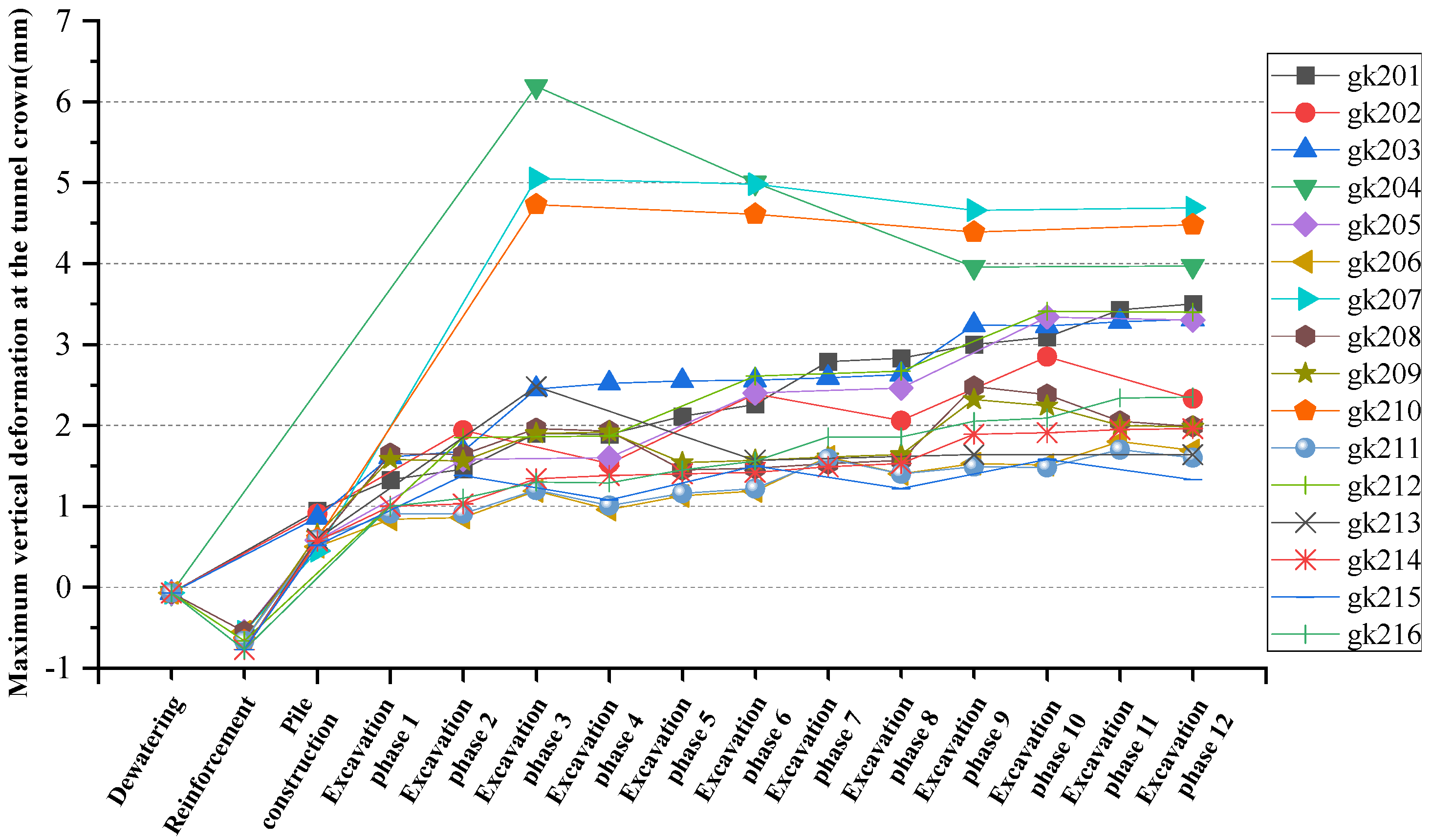
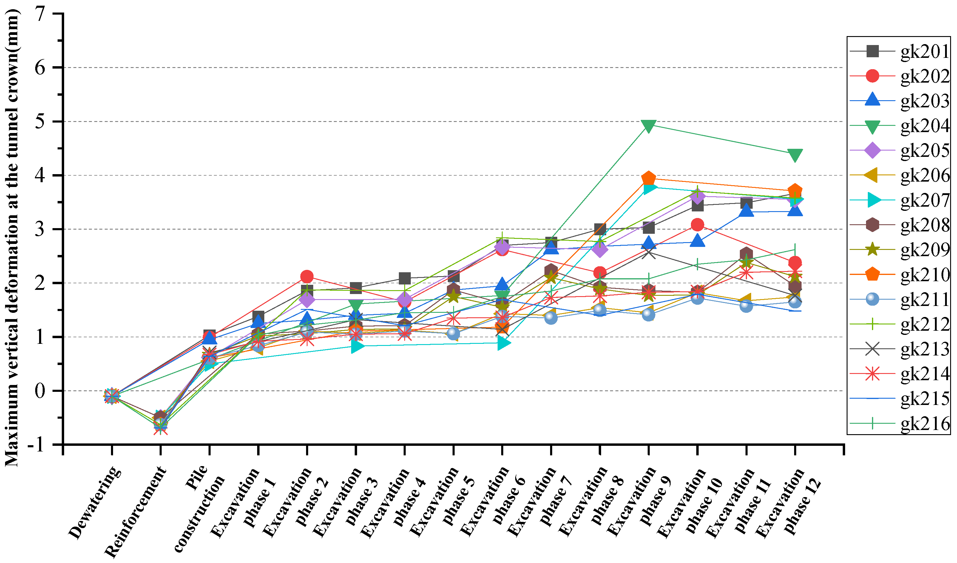
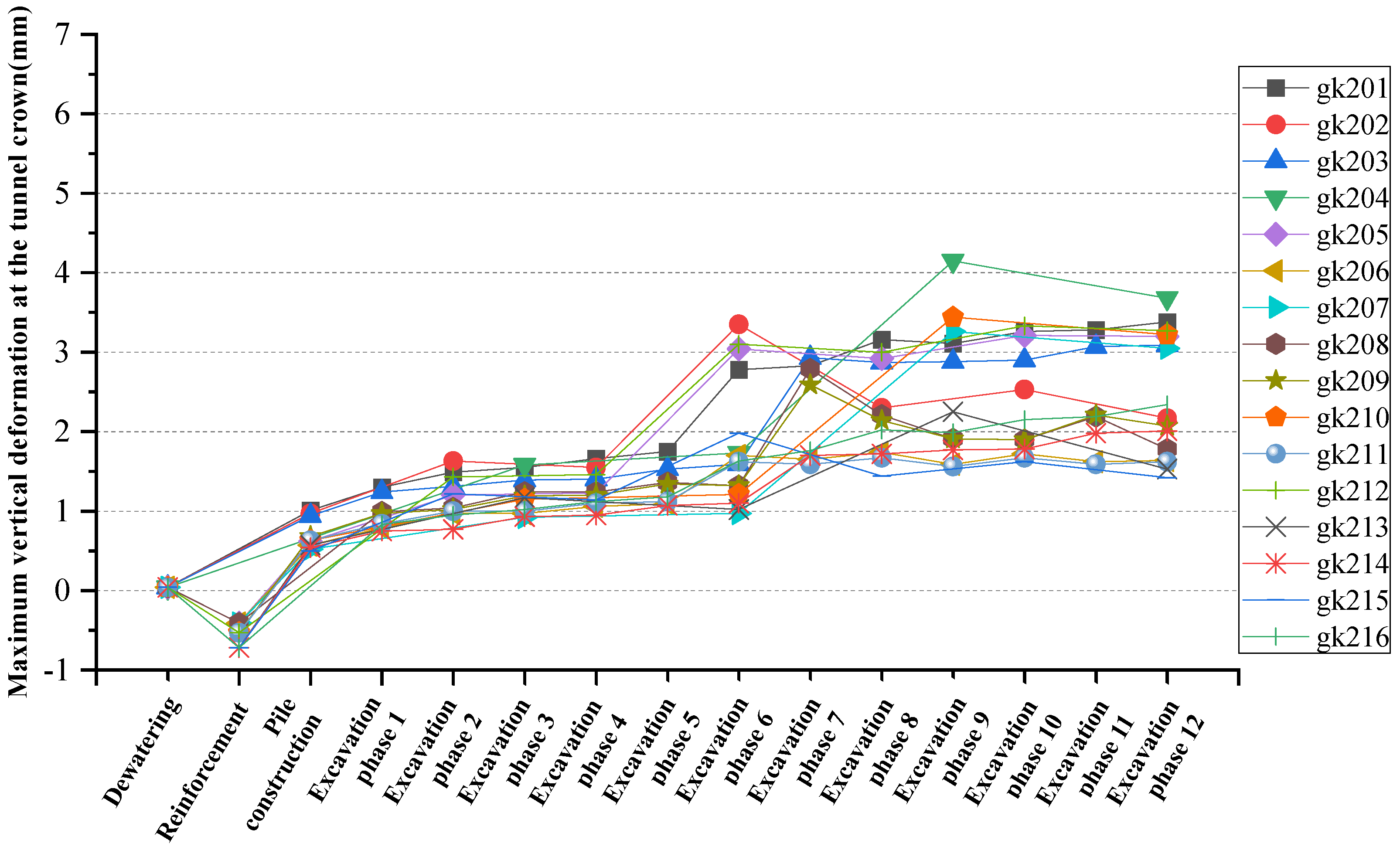
4.2. Development of Vertical Deformation of Tunnel Vault

This section will further analyze the vertical deformation response of typical tunnel cross-sections throughout the whole construction process. The locations of typical cross-sections are shown in Figure 11. Among them, section 1# forms the portal frame structure first, while sections 2# and 3# are located at the centerline of the foundation pit. The development curves of vertical deformation of the vaults at various sections are shown in Figure 12, Figure 13, Figure 14 and Figure 15.
The horizontal design of the excavation method results in different numbers of excavation steps for each working condition. In order to facilitate analysis, the excavation steps under different excavation methods need to be corresponded with Figure 6, as shown in Table 5 in detail.
From Figure 12, Figure 13, Figure 14 and Figure 15, it can be seen that:
(1) Overall, each cross-section’s vertical deformation fluctuates as the foundation pit is gradually excavated, and the fluctuation range is more significant in the case of backfilling. The deformation of cross-sections 2# and 3#, which are situated at the centerline of the foundation pit, is more obvious than that of the cross-sections 1# and 4#. The maximum value occurs in the cross-section 2# under working condition 204.
(2) In terms of specific construction steps, localized precipitation leads to a slight growth in the effective stress of the ground covering the tunnel, resulting in a slight tunnel settlement. Stratum reinforcement increases soil density while enhancing soil properties, and tunnel settlement continues to develop. During the construction of the uplift-resisting piles, the water table rose and the tunnel shifted from settlement to heave due to local unloading. After the foundation pit excavation, the heave of the tunnel gradually rises, mainly occurring during the upper block excavation stage of the cross-sections.
(3) The cross-section 1# first forms the overall structure of the pile-slab frame. After the frame is formed, the influence of other block excavations on its deformation is already very slight, and the vertical deformation tends to be stable. Except for some working conditions, the deformation increment does not exceed 0.5 mm.
(4) Before excavation step 5, the vertical deformation of cross-section 4# is not obvious, and it can be seen that the impact scope of block excavation is about twice the excavation depth of the foundation pit.

5. Effectiveness Analysis of Control Measures Implementation

The main focus of subway tunnel security control includes vertical and horizontal tunnel deformation, longitudinal curvature radius, relative deformation, etc. According to the vertical and horizontal deformation distribution and development law of the tunnel, the vertical deformation response of the tunnel under test conditions is relatively sensitive, while the index values of longitudinal curvature radius and relative deformation are far from the control standards. Therefore, this section will conduct an extreme value analysis using the vertical deformation of the arch vault as an indicator to investigate the impact of each zone group factor on the deformation of the existing tunnels.

5.1. Overall Information on Tunnel Vertical Deformation Control
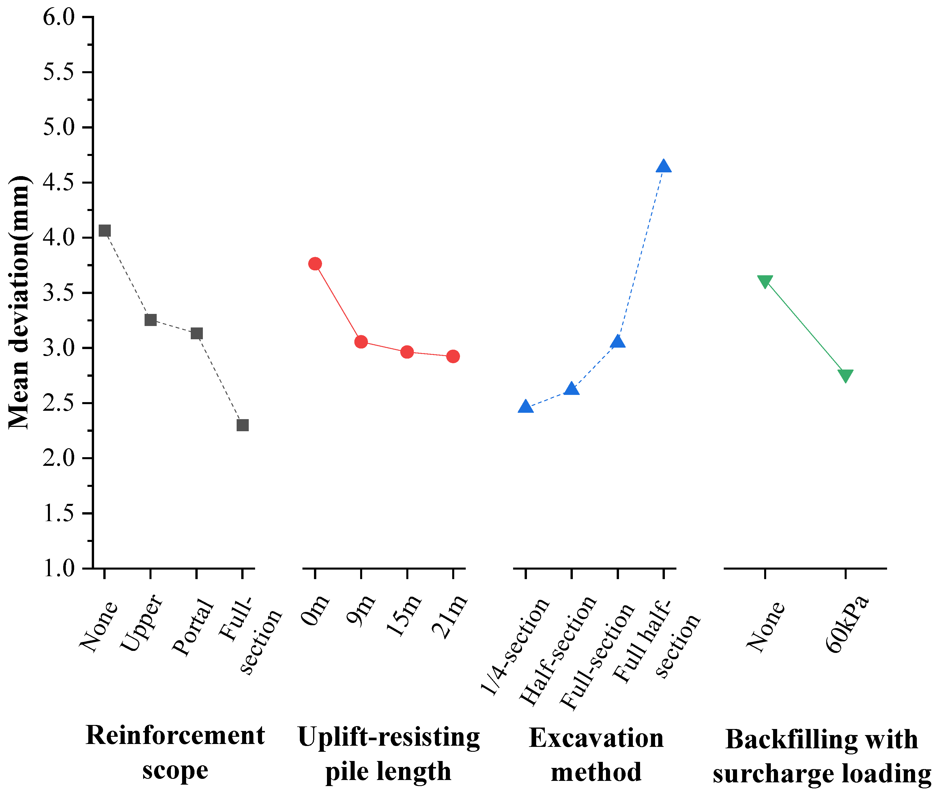
The extreme values of the vertical deformation of the arch vault during the whole construction of each test working condition are condensed in Table 6.
The maximum vertical deformation in each working condition is 6.19 mm, the minimum is 1.67 mm, and the fluctuation range is 4.47 mm. Under the orthogonal combination of various measures, the tunnel deformation indexes are all less than 10 mm, which is the requirement of the Shenzhen metro protection control standard. This shows that, in the absence of special geological conditions, the selection of shallowly buried tunnel upper shallow foundation pit excavation control measures is relatively flexible.

5.2. Range Analysis

Range analysis allows for a visual comparison of each factor’s benefits and drawbacks and the specific levels of factors. The analysis mainly includes the deviation sum K of each level of the factors and the corresponding average deviation K ¯ . The range value R of each factor can be obtained by the following formula:
R = max K ¯ i min K ¯ i
The number of factor levels in each zone group in this orthogonal experiment is not exactly the same. When calculating the factor range value R , the converted range value R should be used, which is calculated using Formula (2):
R = d × R × r
With the formula above, d is the conversion factor corresponding to the number of factor levels m, which can be obtained from Table 7, and r is the average number of test repetitions for each level of the factor.
The range vertical deformation of the tunnel arch vault in the orthogonal experiment is taken as the analysis index, and an analysis of the range is conducted. The outcomes are displayed in Table 8.
The relationship between each factor and the test index is shown in Figure 16, where the length and excavation method of the uplift-resisting pile are randomly arranged during the test level design, and the order is adjusted during plotting according to the monotonicity principle.
From Table 8 and Figure 16, it can be seen that:
(1) The order of influence of each zone group factor on the vertical deformation of the tunnel vault, ranked from most to least significant, is excavation method, backfilling and surcharge loading, reinforcement scope, and the length of uplift-resisting pile.
(2) Because the vertical deformation of each working condition is much greater than the horizontal deformation, and the correlation between each factor and the vertical deformation index shows a monotonic change trend. Therefore, it can be judged that the optimal level combination of each factor is overall reinforcement, uplift-resisting piles with a length of 21 m, 1/4-section zoned excavation, and 60 kPa surcharge loading.
(3) From the perspective of influence trends of each factor on vertical deformation, with the reinforcement range increasing, the vertical deformation of the tunnel reduces significantly and overall reinforcement reduces deformation by 1.7 mm compared to no reinforcement, while the vertical deformation control effects on the tunnel of upper reinforcement and portal reinforcement are not significantly different and overall reinforcement is more restricted. Under the test working conditions, the vertical deformation of the tunnel is significantly reduced after the uplift-resisting piles are set, but the change in pile length has little impact on the control effect. The size of the excavation area has the largest influence on the vertical deformation of the tunnel, and the increase in the excavation area along the longitudinal direction of the tunnel has a larger influence than the increase in the excavation area along the lateral side of the tunnel. Backfilling and surcharge loading, whether or not portal frame structures are used, has a positive impact on deformation control of the existing tunnel.
(4) When formulating a deformation control plan for an existing tunnel for upper foundation pit projects of similar shallow buried tunnels, priority should be given to determining the optimal excavation plan, which is the 1/4-section zoned excavation plan. The excavation range of each block is 7.2 to 8.5 m along the lengthways side of the tunnel and 7.5 to 0.5 m along the lateral side of the tunnel. According to the actual engineering situation, the combination of stratum reinforcement, either upper reinforcement or portal-frame reinforcement, and backfilling and surcharge loading is used. If portal frame anti-heave structures are used from a safety perspective, consideration can be given to optimizing the length of the uplift-resisting piles and the scope of stratum reinforcement, increasing the area of block excavation, and simplifying the construction process.

5.3. Field-Measured Analysis of Control Effectiveness of Portal Frame Anti-Heave Structures

Relying on the project, a combination of portal reinforcement, anti-heave frame, step excavation, and surcharge loading is adopted as a powerful control measure, and it takes nine steps to complete the foundation pit excavation, with the specific construction steps in sequence being construction precipitation, rockfill replacement, rotary spray reinforcement, water level restoration, uplift-resisting piles, block excavation, construction of baseplates, construction of sidewalls, and backfilling and surcharge loading. The tunnel with monitoring cross-section L6, which forms portal frame structures at the top, is the object of analysis, and the pertinent and numerical results of the incremental vault deformation during the foundation pit excavation stage are displayed in Figure 17.
As shown in Figure 17, from the numerical pattern, the measured data of the L6 section show a negative change before 18 June 2020, with a maximum deformation value of −0.5 mm, and then they continue to fluctuate and rise as time goes on, rising to a positive maximum value of 2.5 mm on 24 July 2020. After that, the deformation value fluctuates slowly between 1 mm and 2 mm. The corresponding numerical simulation value rises slowly from 0 mm at the beginning to the maximum value of 1.6 mm on 23 September 2020, and then stabilizes at 1.5 mm. From the comparison pattern, in general, the two changes go in opposite directions from the beginning to 18 June 2020, and then slowly increase in the same direction. Locally, the difference between the two changes from 18 June 2020, to 23 September 2020, is large, but since then the difference gradually decreases, showing a better fit.
From Figure 17, it can be seen that:
(1) In actual construction, there are uncertainties such as non-uniform distribution of strata, over-excavation, irregular slopes, construction access road maintenance, temporary soil loading and unloading, etc. However, through refined modeling, reasonable constitutive relation selection, and the reasonable restoration of the construction process, the numerical analysis and the measured results can still fit well even within a small deformation range, basically reflecting the tunnel’s deformation response during the key establishing steps of the foundation pit excavation process.
(2) Both the measured and numerical results show that, after the L6 cross-section forms the frame structure first in excavation steps 3 and 4, the heave deformation of the existing tunnel has stabilized. This shows that, when the excavation depth is not great, the portal frame structures can effectively suppress the influence of adjacent block excavation on the existing tunnel below. In excavation steps 1 and 2, the measured data are greater than in the case with piles because, in actual construction, over-excavation occurs during the excavation of both the first and second sub-blocks, and the repair of the shortcuts required for mechanical excavation actually increases the soil unloading range.
(3) The uplift generated during the stage of block excavation above the L6 cross-section accounts for about 60% of the final uplift, with a maximum uplift of 2.3 mm, which is much less than the subway safety control index. This shows that there is a large margin of control for the measures adopted, and the implementation costs and construction period of various measures can be comprehensively considered for appropriate optimization to further improve cost-effectiveness.

6. Conclusions

This paper systematically analyzes the application of portal frame anti-heave structures in shallow foundation pit engineering projects above the existing tunnels and the main conclusions are as follows:
(1) The portal frame anti-heave structures perform well in shallow foundation pits when combined with block excavation, stratum reinforcement, backfilling, and surcharge loading. Among these measures, block excavation most effectively controls tunnel deformation, followed by stratum reinforcement.
(2) The different control measure combinations lead to varied deformation extremes in existing tunnels, though they share similar distribution patterns, peak locations, and influence ranges. In 16 orthogonal test working conditions, the excavation-stage maximum vertical deformation ranged from 1.67 to 6.19 mm, revealing substantial optimization potential in control strategy selection.
(3) The portal frame anti-heave structures effectively reduce the existing tunnel deformation caused by adjacent excavation. When combined with uplift-resisting piles and anti-floating slabs forming a frame, the tunnel stability improves. In shallow foundation pit projects, these structures allow for the simplification of other control measures.

Author Contributions

Conceptualization and writing—original draft, J.H.; methodology and resources, J.O.; formal analysis and validation, X.C.; project administration and resources, S.L.; writing—review and editing and visualization, X.Z.; writing—review and editing and visualization, K.H. All authors have read and agreed to the published version of the manuscript.

Funding

This work was supported by the financial support from Analysis and Research on the Impact of Upper Pit Construction on the Deformation of Existing Tunnels and Control Technologies (Grant No. ZHDT-3T-KY004/2019), Guangdong Key Area R&D Program Project “Key Technology of Concealed Excavation Stations of Metro in Busy Urban Areas” (Grant No. 2019B111105001) and the Natural Science Foundation of Inner Mongolia Autonomous Region of China (Grant No. 2024MS05060).

Data Availability Statement

Restrictions apply to the availability of these data. Data were obtained from Shenzhen Metro Group Co., Ltd., and are available from the corresponding author with the permission of Shenzhen Metro Group Co., Ltd.

Conflicts of Interest

Authors Jun He and Shuya Liu were employed by the company Shenzhen Metro Group Co., Ltd. The remaining authors declare that the research was conducted in the absence of any commercial or financial relationships that could be construed as a potential conflict of interest.

Correction Statement

This article has been republished with a minor correction to the existing affiliation information and a minor correction to the Conflicts of Interest Statement. The changes do not affect the scientific content of the article.

References

  1. Xie, C.; Qu, Y.; Lu, H.; Song, S. Study on Deformation of New Tunnels Overcrossing Existing Tunnels Underneath Operating Railways. Buildings 2024, 14, 2420. [Google Scholar] [CrossRef]
  2. Yoo, C.; Cui, S. Effect of New Tunnel Construction on Structural Performance of Existing Tunnel Lining. Geomech. Eng. 2020, 22, 497–507. [Google Scholar] [CrossRef]
  3. Lin, X.; Chen, R.; Wu, H.; Cheng, H. Deformation Behaviors of Existing Tunnels Caused by Shield Tunneling Undercrossing with Oblique Angle. Tunn. Undergr. Space Technol. 2019, 89, 78–90. [Google Scholar] [CrossRef]
  4. Tu, S.; Li, W.; Zhang, C.; Wang, L.; Jin, Z.; Wang, S. Seepage Effect on Progressive Failure of Shield Tunnel Face in Granular Soils by Coupled Continuum-Discrete Method. Comput. Geotech. 2024, 166, 106009. [Google Scholar] [CrossRef]
  5. Jin, Z.; Zhang, C.; Li, W.; Tu, S.; Wang, L.; Wang, S. Stability Analysis for Excavation in Frictional Soils Based on Upper Bound Method. Comput. Geotech. 2024, 165, 105916. [Google Scholar] [CrossRef]
  6. Tu, S.; Li, W.; Zhang, C.; Chen, W. Effect of Inclined Layered Soils on Face Stability in Shield Tunneling Based on Limit Analysis. Tunn. Undergr. Space Technol. 2023, 131, 104773. [Google Scholar] [CrossRef]
  7. Liu, J.; Xue, B.; Wang, H.; Zhang, X.; Zhang, Y. Numerical Study on the Behavior of an Existing Tunnel during Excavating Adjacent Deep Foundation Pit. Sustainability 2023, 15, 9740. [Google Scholar] [CrossRef]
  8. Zhang, S.; Rodriguez-Dono, A.; Song, F.; Zhou, Z. Time-Dependent Tunnel Deformations: Insights from in-Situ Tests and Numerical Analyses. Tunn. Undergr. Space Technol. 2025, 157, 106319. [Google Scholar] [CrossRef]
  9. Ng, C.W.W.; Shi, J.; Hong, Y. Three-Dimensional Centrifuge Modelling of Basement Excavation Effects on an Existing Tunnel in Dry Sand. Can. Geotech. J. 2013, 50, 874–888. [Google Scholar] [CrossRef]
  10. Schweiger, H.F.; Kummerer, C.; Otterbein, R.; Falk, E. Numerical Modelling of Settlement Compensation by Means of Fracture Grouting. Soils Found. 2004, 44, 71–86. [Google Scholar] [CrossRef]
  11. Komiya, K.; Soga, K.; Akagi, H.; Jafari, M.R.; Bolton, M.D. Soil Consolidation Associated with Grouting during Shield Tunnelling in Soft Clayey Ground. Géotechnique 2001, 51, 835–846. [Google Scholar] [CrossRef]
  12. El-Kelesh, A.M.; Mossaad, M.E.; Basha, I.M. Model of Compaction Grouting. J. Geotech. Geoenviron. Eng. 2001, 127, 955–964. [Google Scholar] [CrossRef]
  13. Cai, G.; Jiang, C.; Liu, Z.; Hu, J. Study on Construction Deformation Law of Shield Tunnel Overlapping through the Subway Tunnel. J. Transp. Sci. Eng. 2022, 38, 54–61. [Google Scholar] [CrossRef]
  14. Pang, B.; Lin, P.; Ding, C.; Shi, J. Study on Three-Dimensional Deformation Characteristics of Adjacent Operating Tunnel Caused by Foundation Pit Excavation. Railw. Eng. 2022, 62, 117–120. [Google Scholar]
  15. Wu, H.; Lan, G.; Liu, Y.; Chen, R.; Meng, F.; Xu, X. Field Performance of an Anti-Uplift Portal Frame in Control of the Tunnel Uplift Induced by Overlying Excavation. Tunn. Undergr. Space Technol. 2023, 132, 104908. [Google Scholar] [CrossRef]
  16. Liu, Y.; Chen, R.; Cheng, H.; Wu, H.; Zhang, K. Analytical Solutions for Performance of Existing Shield Tunnel Subjected to Overlying Excavation under Anti-Uplift Portal Frame. Chin. J. Geotech. Eng. 2024, 46, 1675–1684. [Google Scholar] [CrossRef]
  17. Wu, H.; Feng, D.; Liu, Y.; Lan, G.; Chen, R. Anti-Uplift Portal Frame in Control of Underlying Tunnel Deformation Induced by Foundation Pit Excavation. J. Shanghai Jiaotong Univ. 2022, 56, 1227–1237. [Google Scholar] [CrossRef]
  18. Zhang, X.; Luo, B.; Xu, Y.; Yang, Z. Theoretical Analysis of Stratum Horizontal Displacements Caused by Small Radius Curve Shield Tunneling. Comput. Geotech. 2024, 165, 105950. [Google Scholar] [CrossRef]
  19. Zhang, X.; Luo, B.; Xu, Y.; Zhao, C.; Wang, H. Case Study of Performance Assessment of Overlapping Shield Tunnels with a Small Curve Radius. Deep Undergr. Sci. Eng. 2024, 3, 481–496. [Google Scholar] [CrossRef]
  20. Zhang, X.; Qu, H.; Xu, Y.; Zhang, L.; Zhang, Z. Investigating the Damage to Masonry Buildings during Shield Tunneling: A Case Study in Hohhot Metro. Eng. Fail. Anal. 2024, 160, 108147. [Google Scholar] [CrossRef]
  21. Liu, X.; Fang, Q.; Zhang, D.; Wang, Z. Behaviour of Existing Tunnel Due to New Tunnel Construction Below. Comput. Geotech. 2019, 110, 71–81. [Google Scholar] [CrossRef]
  22. Fang, Q.; Zhang, D.; Li, Q.; Wong, L.N.Y. Effects of Twin Tunnels Construction beneath Existing Shield-Driven Twin Tunnels. Tunn. Undergr. Space Technol. 2015, 45, 128–137. [Google Scholar] [CrossRef]
  23. Ye, F.; He, C.; Zhu, H.; Sun, H. Longitudinal Equivalent Rigidity Analysis of Shield Tunnel Considering Transverse Characteristics. Chin. J. Geotech. Eng. 2011, 33, 1870–1876. [Google Scholar]
  24. Huang, H.; Huang, X.; Schweiger, H.F. Numerical Analysis of the Influence of Deep Excavation on underneath Existing Road Tunnel. China Civ. Eng. J. 2012, 45, 182–189. [Google Scholar] [CrossRef]
Figure 1. Section 1 of foundation pit (mm).
Buildings 15 01943 g001
Figure 2. Section 2 of foundation pit (mm).
Buildings 15 01943 g002
Figure 3. Numerical model.
Buildings 15 01943 g003
Figure 4. Portal frame structures and tunnel location.
Buildings 15 01943 g004
Figure 5. Level of stratum reinforcement: (a) unreinforced; (b) upper reinforcement; (c) portal frame reinforcement; (d) full-section reinforcement.
Buildings 15 01943 g005
Figure 6. Series of excavation method: (a) 1/4-section zoned excavation; (b) full-section zoned excavation; (c) half-section zoned excavation; (d) full half-section zoned excavation. Note: Each serial number in the figure represents the block area under each excavation method, and the numbers are the sequential excavation order from small to large.
Buildings 15 01943 g006
Figure 7. Vertical deformation distribution of existing tunnels: (a) vertical deformation distribution of the vault of the left-line tunnel; (b) vertical deformation distribution of the vault of the right-line tunnel.
Buildings 15 01943 g007
Figure 8. Horizontal deformation distribution of existing tunnels: (a) horizontal deformation distribution of the left-line tunnel; (b) horizontal deformation distribution of the right-line tunnel.
Buildings 15 01943 g008
Figure 9. Deformation distribution of the existing tunnel left and right lines under working condition gk204: (a) vertical deformation; (b) horizontal deformation.
Buildings 15 01943 g009
Figure 10. Deformation distribution of the existing tunnel left and right lines under working condition gk207: (a) vertical deformation; (b) horizontal deformation.
Buildings 15 01943 g010
Figure 11. Location of analyzing sections.
Buildings 15 01943 g011
Figure 12. Vertical deformation development curve of arch crown of section 1#.
Buildings 15 01943 g012
Figure 13. Vertical deformation development curve of arch crown of section 2#.
Buildings 15 01943 g013
Figure 14. Vertical deformation development curve of arch crown of section 3#.
Buildings 15 01943 g014
Figure 15. Vertical deformation development curve of arch crown of section 4#.
Buildings 15 01943 g015
Figure 16. Trend chart of influence of vertical deformation factors.
Buildings 15 01943 g016
Figure 17. Measurement of vertical deformation of the L6 cross-section vault during excavation and numerical time history curve. Note: The “a-b” on the upper side of the figure: “a” represents the sequence of block excavation, while “b” represents the specific construction process for each block.
Buildings 15 01943 g017
Table 1. Design parameters of portal frame anti-heave structures in typical cross-sections.
No.Existing TunnelTunnel Burial DepthPit DepthUnloading RatioPile LengthPile DiameterAnti-Floating Slab Thickness
mmmmm
1Line 511.107.800.7019.001.200.60
2Line 112.334.730.3818.171.200.60
3Line 513.858.000.5820.001.000.60
4Line 1115.058.550.5720.001.000.60
5Line 313.708.000.5824.451.003.00
6Line 9 west extension11.646.930.615.441.2/1.00.30
7Line 115.5012.500.8123.601.200.50
8Line 1116.306.550.4028.001.201.00
9Line 1113.444.100.3124.801.802.50
10Line 512.388.500.6924.501.802.50
11Line 216.8012.000.7125.001.2/1.52.50
12Line 1122.5017.100.7618.001.000.90
1322.5016.500.7318.001.000.90
1420.0014.900.7518.001.000.90
15Line 98.505.000.6322.001.201.00
Table 2. pH model parameters of stratum.
ParameterUnitFill SoilFill StoneCohesive SoilRemnant SoilFully Weathered GraniteStrongly Weathered Granite
lim2.02.03.512.015.015.5
E 50 r e f MPa4.96.45.75.25.412.8
E ur r e f MPa19.725.621.832.833.957.5
ckPa13.55.023.823.025.035.0
φ°16.130.918.020.225.033.0
ψ°000000
m-0.950.950.930.760.850.80
Rf-0.900.900.940.730.710.90
E 0 r e f MPa141.9385.6189.3260.6421.51204.0
γ0.710−42.02.02.21.71.42.0
E o e d r e f MPa3.56.44.75.25.412.8
n-0.350.350.350.350.330.33
e-0.740.800.751.010.720.60
γkN/m319.219.519.618.118.519.0
prefkPa100.0
Notes: E 50 r e f : cutline stiffness at half the breaking strength at the reference perimeter pressure; E ur r e f : unloaded reloading stiffness at the reference perimeter pressure; m: stress correlation coefficient; Rf: breakage ratio; E 0 r e f : initial modulus at the reference perimeter pressure; γ0.7: shear strain threshold; E o e d r e f : tangent stiffness at the reference perimeter pressure; pref: reference perimeter pressure.
Table 3. Factors of the orthogonal experiment.
FactorFactor 1Factor 2Factor 3Factor 4
Reinforcement RangeAnti-Pulling Pile LengthExcavation MethodBackfill Load
Level 1None9 m1/4-section zoned excavationNone
Level 2Upper15 mFull-section zoned excavation60 kPa
Level 3Portal21 mHalf-section zoned excavation-
Level 4Full-section0 mFull half-section zoned excavation-
Table 4. The scheme of the orthogonal experiment.
Working ConditionReinforcement RangePile LengthExcavation MethodSurcharge Loading
gk201None9 m1/4-section zoned excavationNone
gk202None15 mFull-section zoned excavation60 kPa
gk203None21 mHalf-section zoned excavationNone
gk204None0 mFull half-section zoned excavation60 kPa
gk205Upper9 mFull-section zoned excavationNone
gk206Upper15 m1/4-section zoned excavation60 kPa
gk207Upper21 mFull half-section zoned excavationNone
gk208Upper0 mHalf-section zoned excavation60 kPa
gk209Portal9 mHalf-section zoned excavation60 kPa
gk210Portal15 mFull half-section zoned excavationNone
gk211Portal21 m1/4-section zoned excavation60 kPa
gk212Portal0 mFull-section zoned excavationNone
gk213Full-section9 mFull half-section zoned excavation60 kPa
gk214Full-section15 mHalf-section zoned excavationNone
gk215Full-section21 mFull-section zoned excavation60 kPa
gk216Full-section0 m1/4-section zoned excavationNone
Table 5. Corresponding setting of excavation steps.
Excavation Phase1/4-Section Zoned ExcavationFull-Section Zoned ExcavationHalf-Section Zoned ExcavationFull Half-Section Zoned Excavation
1No. 1 pit backfill No. 1 pit excavation
2No. 2 pit backfillNo. 1 pit excavationNo. 1 pit backfill
3No. 3 pit backfill No. 2 pit excavationNo. 1 pit excavation
4No. 4 pit backfillNo. 1 pit backfillNo. 2 pit backfill
5No. 5 pit backfill No. 3 pit excavation
6No. 6 pit backfillNo. 2 pit excavationNo. 3 pit backfillNo. 1 pit backfill
7No. 7 pit backfill No. 4 pit excavation
8No. 8 pit backfillNo. 2 pit backfillNo. 4 pit backfill
9No. 9 pit backfill No. 5 pit excavationNo. 2 pit excavation
10No. 10 pit backfillNo. 3 pit excavationNo. 5 pit backfill
11No. 11 pit backfill No. 6 pit excavation
12No. 12 pit backfillNo. 3 pit backfillNo. 6 pit backfillNo. 2 pit backfill
Table 6. Extreme values of vertical deformation during construction.
Working ConditionLeft Line Arch
Vertical Deformation (mm)
Right Line Arch
Vertical Deformation (mm)
The Largest Arch
Vertical Deformation (mm)
gk2013.53.663.66
gk2022.853.083.08
gk2033.263.283.28
gk2046.194.946.19
gk2053.343.613.61
gk2061.801.821.82
gk2075.003.735.00
gk2082.482.542.54
gk2092.322.382.38
gk2104.733.944.73
gk2111.651.671.67
gk2123.413.703.70
gk2132.482.572.57
gk2141.962.222.22
gk2151.531.741.74
gk2162.352.622.62
Table 7. Conversion factors.
m2345678910
d0.710.520.450.40.370.350.340.320.31
Table 8. The results of range analysis.
NumLevelReinforcement RangeUplift-Resisting Pile LengthExcavation MethodBackfill Load
K116.2612.229.8228.92
213.0211.8512.1822.09
312.5311.8410.47-
49.215.0518.54-
Kavg14.073.052.463.61
23.252.963.042.76
33.132.922.62-
42.33.764.63-
The best level4312
R−1.77−0.84−2.18−0.85
Level quantity4442
r4448
d0.450.450.450.71
R −1.59−0.76−1.96−1.71
Disclaimer/Publisher’s Note: The statements, opinions and data contained in all publications are solely those of the individual author(s) and contributor(s) and not of MDPI and/or the editor(s). MDPI and/or the editor(s) disclaim responsibility for any injury to people or property resulting from any ideas, methods, instructions or products referred to in the content.

