Analysis of Filled Soil-Induced Pier Offset and Cracking in a Highway Bridge and Retrofitting Scheme Development: A Case Study
Abstract
1. Introduction
2. Project Background
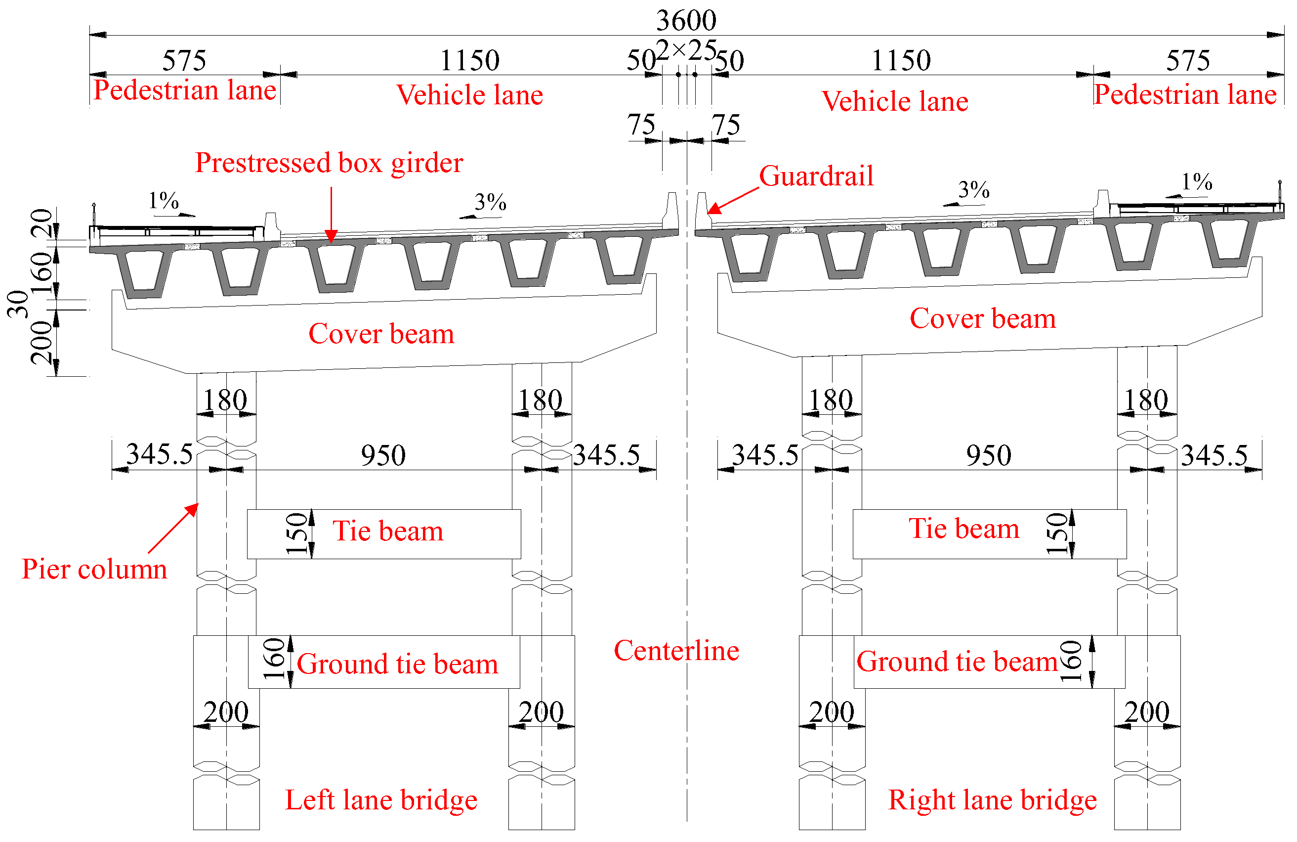
2.1. Bridge Overview and Accident
2.2. Investigation of Geological Conditions at the Bridge Location
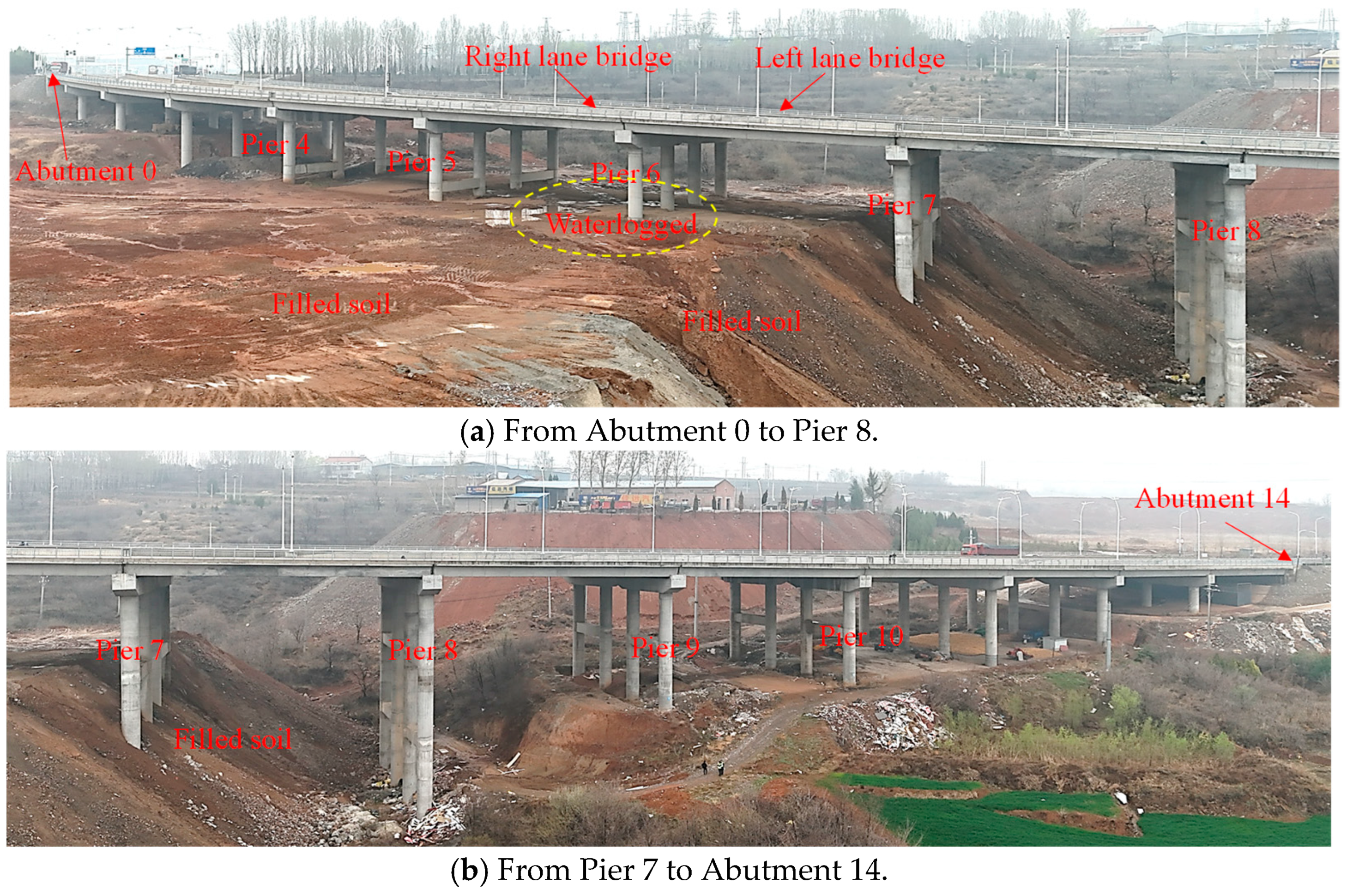
3. Investigation of Filled Soil and Pier Offsets
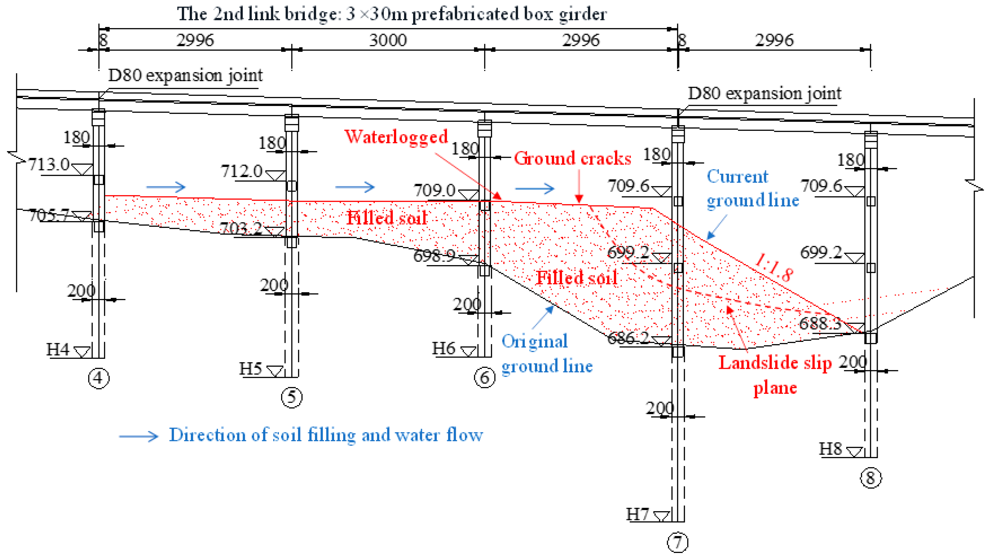
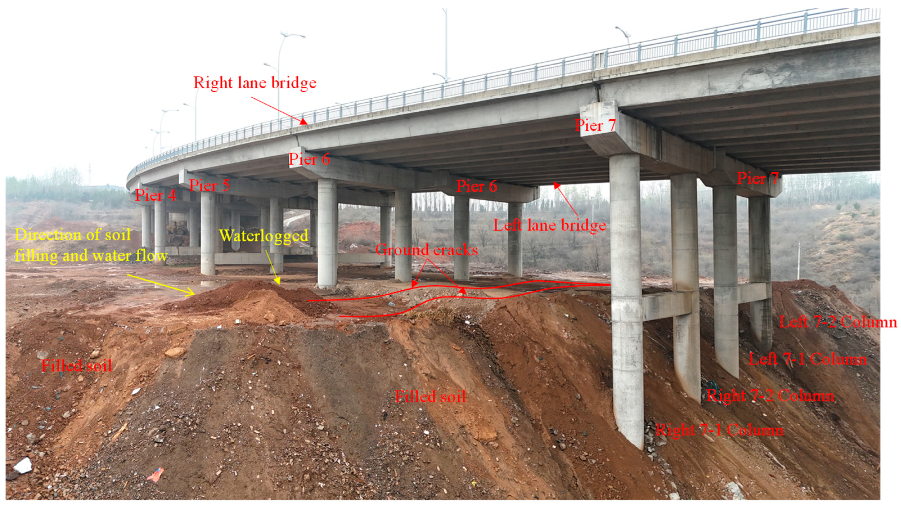
3.1. Investigation of Filled Soil Under the Bridge
3.2. Detection and Analysis of Pier Offset
- The columns of Piers 4–6 for both the left and right lane bridges exhibit satisfactory longitudinal and transverse verticality, with no discernible tilt detected.
- The columns of Pier 7 for the right lane bridge, however, show clear offsets in both the longitudinal and transverse directions. The maximum longitudinal offset was recorded at the 7-1 column, reaching 342.7 mm. Given that the height of the 7-1 column is 31.814 m, the H/1000 limit is 31.814 mm; this longitudinal offset is 10.77 times the H/1000 limit and 17.13 times the 20 mm limit, corresponding to a verticality of 2.57%. Additionally, the maximum transverse offset was observed at the 7-2 column, measuring −258.2 mm. For the 7-2 column with a height of 31.814 m, this transverse offset is 8.12 times the H/1000 limit and 12.91 times the 20 mm limit, resulting in a verticality of −2.05%. These values significantly exceed the normative permissible deviations (≤H/1000 and ≤20 mm, where H is the height of the pier [35]).
- Similarly, the columns of Pier 7 of the left lane bridge also display clear offsets in both the longitudinal and transverse directions. The maximum longitudinal offset at the 7-1 column is 210.9 mm. For the 7-1 column with a height of 31.814 m, this longitudinal offset is 6.63 times the H/1000 limit and 10.55 times the 20 mm limit, corresponding to a verticality of 1.72%. The maximum transverse offset at the 7-1 column is −71.9 mm, which is 2.26 times the H/1000 limit and 3.60 times the 20 mm limit, resulting in a verticality of −0.59%. These values also significantly exceed the normative permissible deviations (≤H/1000 and ≤20 mm, where H is the height of the pier [35]).
4. Risk Assessment of Cracking Using Finite Element Analysis
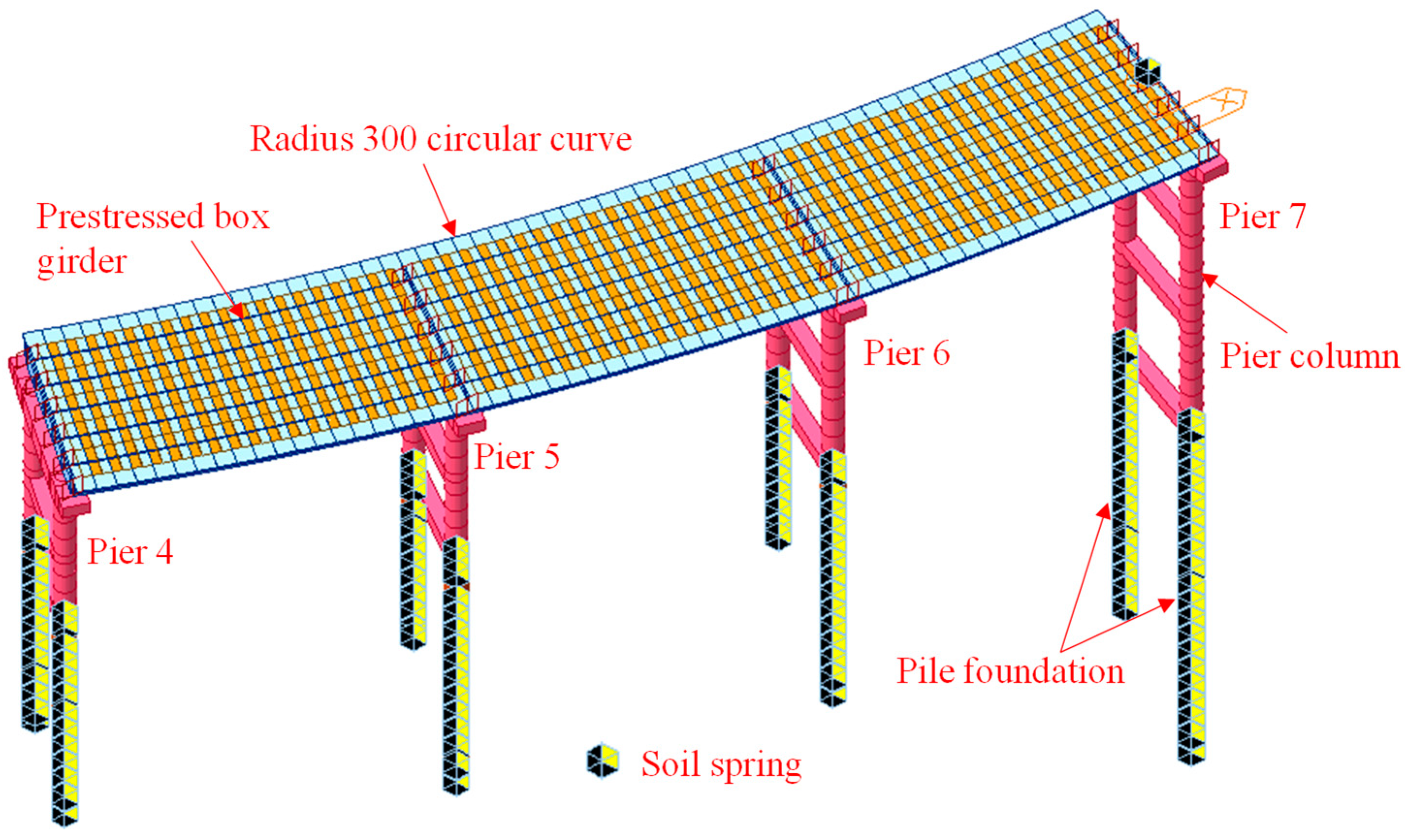
4.1. Finite Element Calculation Model
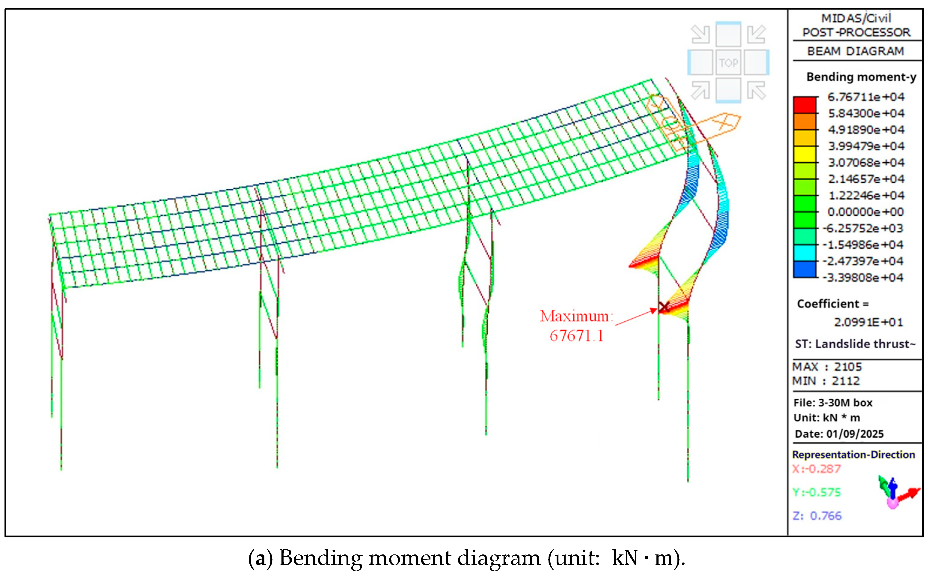
4.2. Cracking Risk Analysis of Pier Columns
5. Unloading Scheme and Inspection of Piers After Unloading
5.1. Unloading Scheme
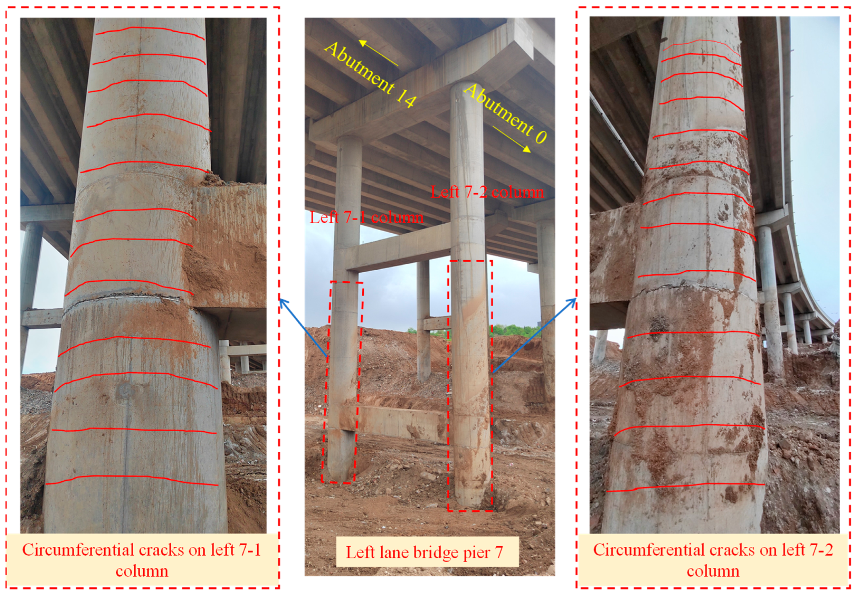
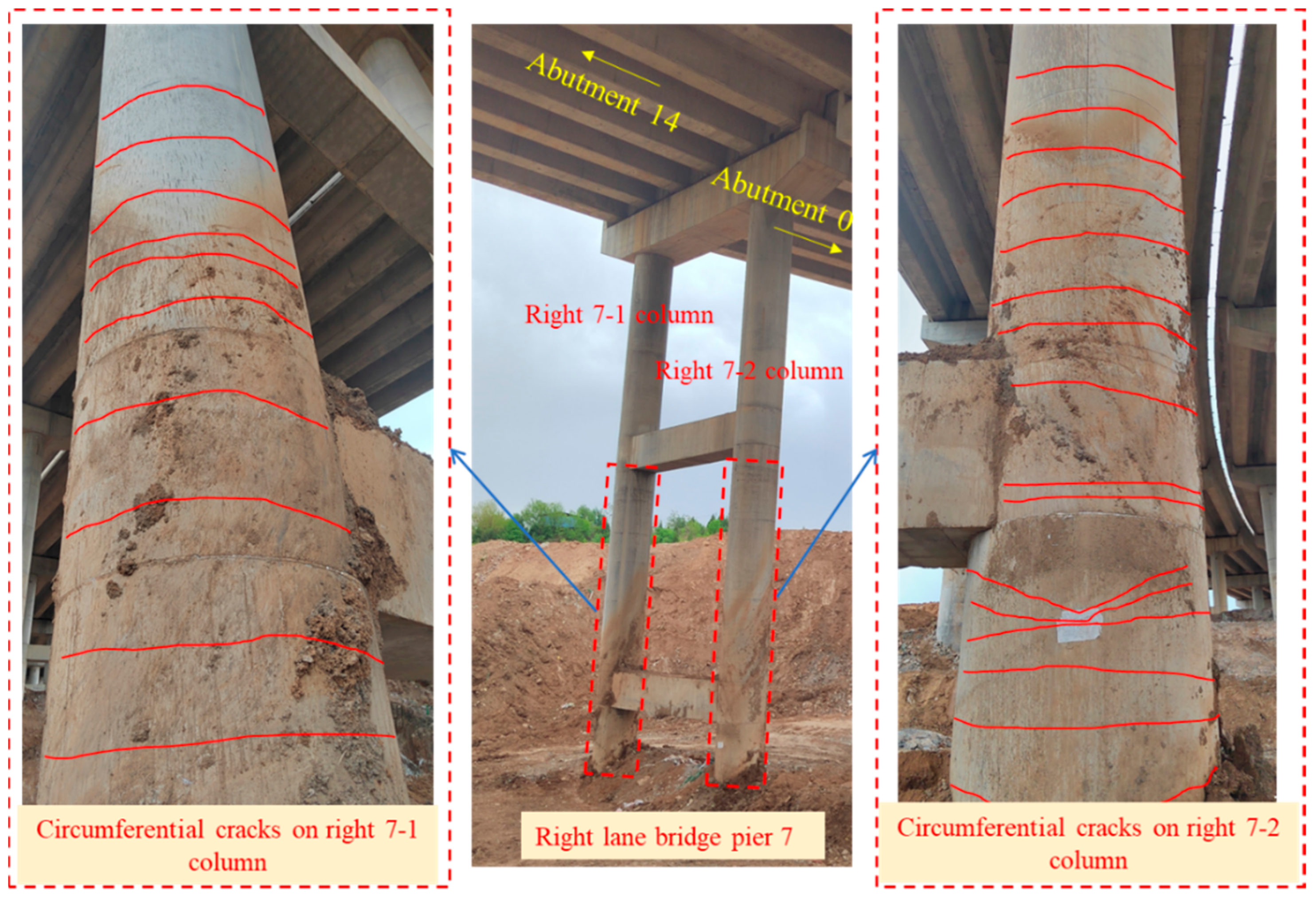
5.2. Crack Inspection of Bridge Piers After Unloading
5.3. Longitudinal Offsets of Columns After Unloading
6. Bridge Pier Reinforcement and Offset Correction Study
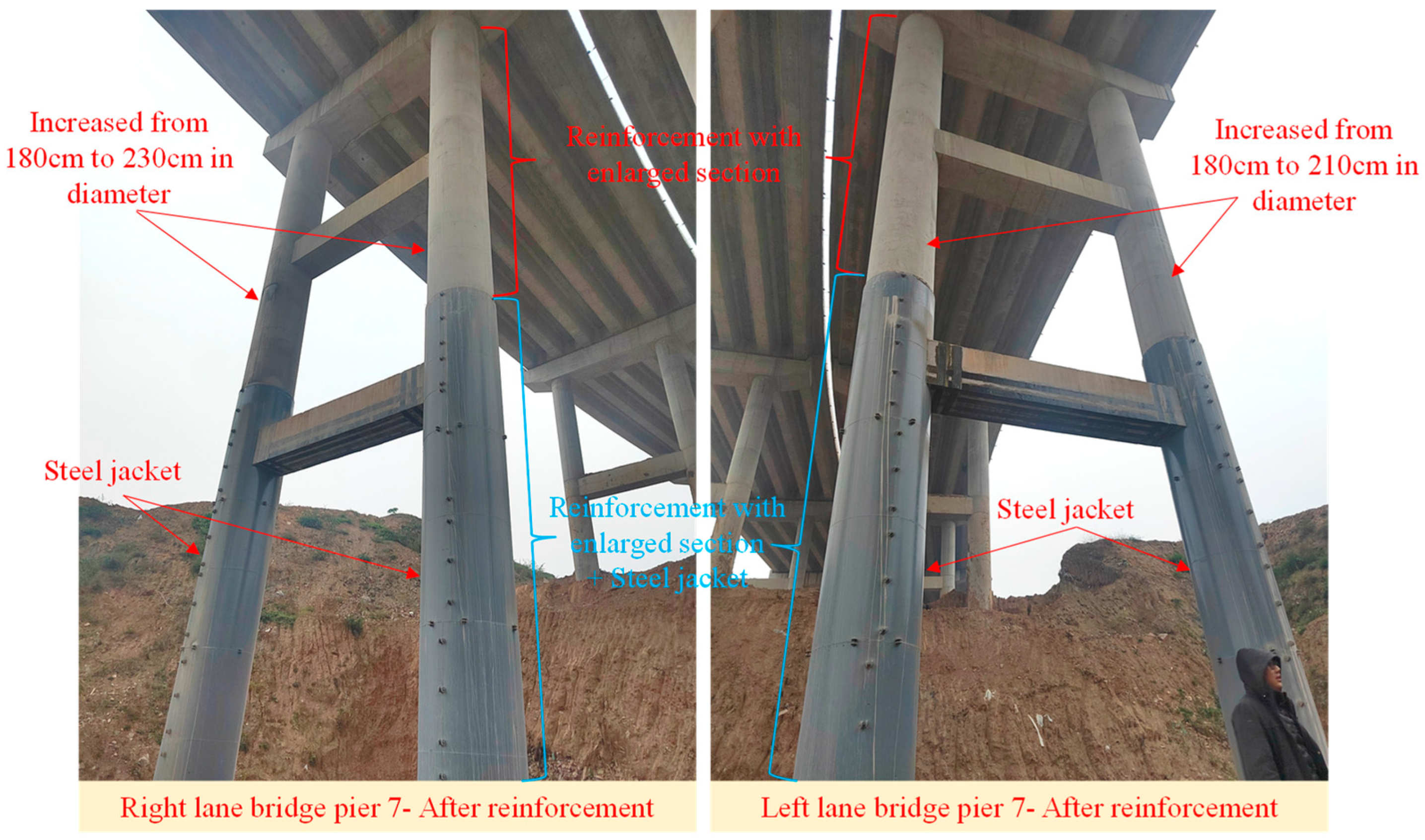
6.1. Reinforcement Scheme Combining Section Enlargement and Steel Jacket
6.2. Bearing Capacity Calculation of Reinforced Columns
7. Conclusions
- Field investigations and geological assessments confirm that the bridge site had stable foundations and no slope stability issues, effectively ruling out slope sliding as the cause of pier displacement. Instead, the accumulation of filled soil beneath the bridge, especially concentrated under the second link bridges of both lanes, was identified as the primary culprit. The filled soil’s sliding and cracking behaviors exerted substantial additional loads on the piers. Finite element analysis quantitatively demonstrated that these additional loads significantly increased the internal forces and displacements of the piers and pile foundations. Notably, the tensile and compressive stresses in the middle and bottom sections of Pier 7 columns far exceeded the design values of C40 concrete, indicating a high risk of cracking in these areas.
- After unloading the filled soil, detailed inspections of the pier columns were carried out. The observed regular annular cracks on the Pier 7 columns of both the left and right lane bridges were in remarkable agreement with the high-risk zones predicted by the finite element analysis. This consistency validates the effectiveness of the integrated approach combining field investigations and numerical simulations in accurately diagnosing bridge damage. It suggests that such an approach can serve as a reliable methodology for similar accident investigations in bridge engineering, enabling engineers to quickly and accurately identify the root causes of structural failures.
- The reinforcement scheme, which combined section enlargement and steel jacket addition for Pier 7 columns, successfully addressed the residual displacement and restored the bearing capacity of the damaged piers. Post-reinforcement measurements showed that the verticality of the columns met the required standards, and load-bearing capacity calculations confirmed that the reinforced piers could safely withstand combined compression and bending forces with a sufficient safety margin. This demonstrates the practicality and effectiveness of the proposed reinforcement strategy, providing a valuable reference for the repair and reinforcement of piers with similar damage patterns.
- From a broader perspective, this study highlights the importance of considering the impact of surrounding soil-related factors, such as filled soil loads, in bridge design, construction, and maintenance. It emphasizes the necessity of strict regulations regarding the disposal of construction waste and soil filling near bridge structures to prevent potential safety hazards. The research methodology and findings can be extended to other bridge projects facing similar challenges, helping engineers to better anticipate, assess, and mitigate risks associated with soil-structure interaction.
Author Contributions
Funding
Data Availability Statement
Conflicts of Interest
References
- Lee, S.; Chang, H.; Lee, J. Construction and Demolition Waste Management and Its Impacts on the Environment and Human Health: Moving Forward Sustainability Enhancement. Sustain. Cities Soc. 2024, 115, 105855. [Google Scholar] [CrossRef]
- Sagan, J.; Mach, A. Construction Waste Management: Impact on Society and Strategies for Reduction. J. Clean. Prod. 2025, 486, 144363. [Google Scholar] [CrossRef]
- Cudecka-Purina, N.; Kuzmina, J.; Butkevics, J.; Olena, A.; Ivanov, O.; Atstaja, D. A Comprehensive Review on Construction and Demolition Waste Management Practices and Assessment of This Waste Flow for Future Valorization via Energy Recovery and Industrial Symbiosis. Energies 2024, 17, 5506. [Google Scholar] [CrossRef]
- de Magalhães, R.F.; de M.F. Danilevicz, Â.; Saurin, T.A. Reducing Construction Waste: A Study of Urban Infrastructure Projects. Waste Manag. 2017, 67, 265–277. [Google Scholar] [CrossRef] [PubMed]
- Islam, N.; Sandanayake, M.; Muthukumaran, S.; Navaratna, D. Review on Sustainable Construction and Demolition Waste Management—Challenges and Research Prospects. Sustainability 2024, 16, 3289. [Google Scholar] [CrossRef]
- Zhao, Y.; Liu, Z.; Liang, T.; He, F.; Zhan, L.; Chen, Y.; Ling, D.; Wang, J. Soil Fluidisation Induced by Fine Particles Migration: Insights from the Shenzhen 2015 Landfill Landslide. Eng. Geol. 2024, 343, 107783. [Google Scholar] [CrossRef]
- Zhang, J.; Qian, J.; Lu, Y.; Li, X.; Song, Z. Study on Landslide Susceptibility Based on Multi-Model Coupling: A Case Study of Sichuan Province, China. Sustainability 2024, 16, 6803. [Google Scholar] [CrossRef]
- Bhuyan, K.; Rana, K.; Ozturk, U.; Nava, L.; Rosi, A.; Meena, S.R.; Fan, X.; Floris, M.; van Westen, C.; Catani, F. Towards Automatic Delineation of Landslide Source and Runout. Eng. Geol. 2024, 345, 107866. [Google Scholar] [CrossRef]
- Haugen, S.; Henderson, A.; Amdal, Å. Case-Study of a Quick Clay Landslide That Caused the Partial Collapse of Mofjellbekken Bridges in Norway; CRC Press: Boca Raton, FL, USA, 2016; pp. 1091–1097. [Google Scholar]
- Arafianto, A.; Rahardjo, P.P. Back-Analysis of Ground Movement Based on Displacement Matching Approach: A Case Study of Landslide at Bridge Abutment Using 3D Finite Element Method; Springer: Singapore, 2021; pp. 1061–1074. [Google Scholar]
- Ma, Y.-G.; Wang, Y.-F.; Chen, C. Force Analysis and Handling Measures for Offsetting of Bridge Passive Piles under Action of Stacked Load. Bridge Constr. 2014, 44, 22–26. [Google Scholar]
- Yang, C.-M.; Chao, W.-A.; Weng, M.-C.; Fu, Y.-Y.; Chang, J.-M.; Huang, W.-K. Outburst Debris Flow of Yusui Stream Caused by a Large-Scale Silabaku Landslide, Southern Taiwan. Landslides 2022, 19, 1807–1811. [Google Scholar] [CrossRef]
- Wang, J.; Wei, K.; Cai, H. Dynamic Response of Cylindrical Bridge Pier Subjected to the Impact of Flash Flooding Considering the Effect of Soil–Structure Interactions. Structures 2025, 72, 108199. [Google Scholar] [CrossRef]
- Jiang, L.; Xiao, W.; Lai, Z.; Mou, B. Dynamic Characteristics and Impact Load Properties of High-Speed Railway Piers under Debris Flow Impact. Transp. Geotech. 2025, 52, 101562. [Google Scholar] [CrossRef]
- Wu, T.; Fan, G.; Dou, C.; Li, X.; Dou, C.; Che, J.; Wang, T.; Rao, J. Simulation Study on Damage Behavior of a Shallow-Buried Foundation Bridge under Combined Action of Flood Scouring and Heavy Vehicle Load. Ocean Eng. 2025, 323, 120410. [Google Scholar] [CrossRef]
- Xiang, W.; Lifang, P.; Honggang, W. Simulation Analysis and Experimental Study on the Damage of Bridge Structure Caused by Tilt Collapse and Rockfall on the Slope of Lalin Railway. Chin. J. Rock Mech. Eng. 2020, 39, 1622–1633. [Google Scholar] [CrossRef]
- Bounds, T.D.; Muraleetharan, K.K.; Miller, G.A. Lateral Movements of Bridge Embankments on Soft Soils: A Case Study Inspired Investigation. Geotech. Geol. Eng. 2023, 42, 121–139. [Google Scholar] [CrossRef]
- Jia, L.; Tao, L.; Hong, H.; Jian, J.; Zhi, H. Experimental Test on Bridge Reinforcement by Enlarging Section-Prestress Method; EDP Sciences: Paris, France, 2020; Volume 165, p. 04015. [Google Scholar]
- Li, W.; Liang, H.; Lu, Y.; Xue, J.; Liu, Z. Axial Behavior of Slender RC Square Columns Strengthened with Circular Steel Tube and Sandwiched Concrete Jackets. Eng. Struct. 2019, 179, 423–437. [Google Scholar] [CrossRef]
- Yang, K.-H. Axial Behavior of Reinforced Concrete Columns Strengthened with New Section Enlargement Approaches. ACI Struct. J. 2019, 116, 87–96. [Google Scholar] [CrossRef]
- Lu, C.; Ouyang, K.; Wang, Q.; Zhu, W.; Chen, H.; Lei, Z.; Qin, Z. Axial Behavior of RC Column Strengthened with Laterally Reinforced FRHPC Jacket. Struct. Concr. 2022, 23, 1718–1734. [Google Scholar] [CrossRef]
- Wang, Y.D.; Yang, S.; Han, M.; Yang, X. Experimental Study of Section Enlargement with Reinforced Concrete to Increase Shear Capacity for Damaged Reinforced Concrete Beams. Appl. Mech. Mater. 2012, 256–259, 1148–1153. [Google Scholar] [CrossRef]
- Liu, H.; Li, J.; Tao, X.; Zhang, H. Research on Assessment of Hollow Slab Bridge Hinge Joint Damage and Reinforcement Method Based on Steel Strip-Tie Rod Clamping. Case Stud. Constr. Mater. 2024, 20, e02885. [Google Scholar] [CrossRef]
- Huber, T.; Grasl, P.; Kleiser, M.; Kromoser, B.; Preinstorfer, P. Holistic Life Cycle Cost Analysis of Road Bridges with Non-Metallic Reinforcement. Dev. Built Environ. 2024, 20, 100533. [Google Scholar] [CrossRef]
- Liu, H.; Li, J.; Zhang, J.; Pang, D. Decision Analysis of a Reinforcement Scheme for In-Service Prestressed Concrete Box Girder Bridges Based on AHP and Evaluation of the Reinforcement Effect. Buildings 2022, 12, 1771. [Google Scholar] [CrossRef]
- CJJ 11-2011; Code for Design of the Municipal Bridge (2019 Edition). Ministry of Housing and Urban-Rural Development of the People’s Republic of China: Beijing, China, 2019.
- Chen, Y.; Wang, H.; Zhang, F.; Meng, Q.; Liu, Z. Study on the Calculation Model of Mutually Embedded Displacement between Miscellaneous Fill and Soft Soil. Bull. Eng. Geol. Environ. 2024, 83, 348. [Google Scholar] [CrossRef]
- Chen, Y.; Qu, X.; Zhang, F.; Liu, Z. Study on the Influence of Matrix on Mechanical and Failure Characteristics of Miscellaneous Fill. J. Test. Evaluation 2024, 52, 1189–1205. [Google Scholar] [CrossRef]
- Tichavský, R.; Ballesteros-Cánovas, J.A.; Šilhán, K.; Tolasz, R.; Stoffel, M. Dry Spells and Extreme Precipitation Are The Main Trigger of Landslides in Central Europe. Sci. Rep. 2019, 9, 14560. [Google Scholar] [CrossRef]
- Qiu, H.; Su, L.; Tang, B.; Yang, D.; Ullah, M.; Zhu, Y.; Kamp, U. The Effect of Location and Geometric Properties of Landslides Caused by Rainstorms and Earthquakes. Landforms 2024, 49, 2067–2079. [Google Scholar] [CrossRef]
- Tang, D.; Huang, M. The Sustainable Development of Bridges in China: Collapse Cause Analysis, Existing Management Dilemmas and Potential Solutions. Buildings 2024, 14, 419. [Google Scholar] [CrossRef]
- Deng, L.; Wang, W.; Yu, Y. State-of-the-Art Review on the Causes and Mechanisms of Bridge Collapse. J. Perform. Constr. Facil. 2015, 30, 04015005. [Google Scholar] [CrossRef]
- Cheng, M.-L.; Gao, W.-W. Study on the Impact Law of V-Shaped Gully Debris Avalanches on Double-Column Piers. Buildings 2024, 14, 577. [Google Scholar] [CrossRef]
- Borowski, L.; Pienko, M.; Wielgos, P. Evaluation of Inventory Surveying of Façade Scaffolding Conducted During ORKWIZ Project. In Proceedings of the 2017 Baltic Geodetic Congress (BGC Geomatics), Gdansk, Poland, 22–25 June 2017; pp. 189–192. [Google Scholar]
- JTG F80/1—2017; Inspection and Evaluation Quality Standards for Highway Engineering: Section 1 Civil Engineering. Research Institute of Highway Ministry of Transport: Beijing, China, 2018.
- Li, X.-M.; Liu, Y.; Wu, H.; Ding, C.-Y.; Dong, J.; Peng, W.; Zhang, D.-H.; Sun, J. A Comprehensive Analytical Model for Tensile-Bending Straightening in Strip Processing by Coupling Residual Stress and Buckling Deformation. J. Mech. Work. Technol. 2025, 339, 118802. [Google Scholar] [CrossRef]
- Yao, S.; Chen, Y.; Sun, C.; Zhao, N.; Wang, Z.; Zhang, D. Dynamic Response Mechanism of Thin-Walled Plate under Confined and Unconfined Blast Loads. J. Mar. Sci. Eng. 2024, 12, 224. [Google Scholar] [CrossRef]
- Sogut, H.; Ozcelik, R.; Sogut, K.; Erdal, F. Experimental Behavior and FE Modeling of Buckling Restrained Braced Frame with Slip-Critical Connection. Appl. Sci. 2025, 15, 5626. [Google Scholar] [CrossRef]
- Gao, L.; Zhuang, M.-L.; Zhang, Q.; Bao, G.; Yu, X.; Du, J.; Zhou, S.; Wang, M. Displacement and Internal Force Response of Mechanically Connected Precast Piles Subjected to Horizontal Load Based on the M-Method. Buildings 2024, 14, 1943. [Google Scholar] [CrossRef]
- Wyllie, D.C.; Mah, C.W. Rock Slope Engineering; CRC Press: Boca Raton, FL, USA, 2017. [Google Scholar]
- Das, M.B.; Sobhan, K. Principles of Geotechnical Engineering; Cengage Learning: Boston, MA, USA, 2018. [Google Scholar]
- JTG 3362-2018; Specifications for Design of Highway Reinforced Concrete and Prestressed Concrete Bridges and Culverts. Ministry of Transport of the People’s Republic of China: Beijing, China, 2018.
- Huang, Y.; Liu, E.; Lu, Y.; Jiao, Y. Axial Performance of Square Steel Tube and Sandwiched Concrete Jacketed Circular CFST Columns. Eng. Struct. 2024, 313, 118200. [Google Scholar] [CrossRef]
- Wan, S.; Li, S.; Chen, Z.; Tang, Y. An Ultrasonic-AI Hybrid Approach for Predicting Void Defects in Concrete-Filled Steel Tubes via Enhanced XGBoost with Bayesian Optimization. Case Stud. Constr. Mater. 2025, 22, e04359. [Google Scholar] [CrossRef]
- Zhuang, L.-D.; Zhao, J.-Z.; Wang, C.; Liang, H.-Q.; Tang, M.-X. Experimental Study on the Composite Reinforcement Method for Single-Column Piers in Existing Bridges. Structures 2024, 65, 106734. [Google Scholar] [CrossRef]
- JTG D60-2015; General Specifications for Design of Highway Bridges and Culverts. Ministry of Transport of the People’s Republic of China: Beijing, China, 2015.
- GB 50936-2014; Technical Code for Concrete Filled Steel Tubular Structures. Ministry of Housing and Urban-Rural Development of the People’s Republic of China: Beijing, China, 2014.
- GB 50017-2017; Standard for Design of Steel Structures. Ministry of Housing and Urban-Rural Development of the People’s Republic of China. General Administration of Quality Supervision, Inspection and Quarantine: Beijing, China, 2017.
- GB 50010-2010 (2015 Edition); Code for Design of Concrete Structures. Ministry of Housing and Urban-Rural Development of the People’s Republic of China. General Administration of Quality Supervision, Inspection and Quarantine: Beijing, China, 2015.






| Soil Layers | Geotechnical Name | Basic Allowable Bearing Capacity (kPa) |
|---|---|---|
| 1 | Plain Fill | 60 |
| 2 | Silty Soil | 140 |
| 3 | Silty Clay | 210 |
| 4 | Limestone | 2000 |
| 5 | Fully Weathered Mudstone | 250 |
| 6 | Moderately Weathered Mudstone | 700 |
| 7 | Sandstone | 2000 |
| 8 | Limestone | 2000 |
| Bridges | Pier Number | Column Number | Design Pier Height (m) | Exposed Pier Height (m) | Thickness of the Fill (m) |
|---|---|---|---|---|---|
| Right lane bridge | Pier 4 | Right 4-1 | 15.015 | 11.08 | 3.94 |
| Right 4-2 | 15.015 | 10.82 | 4.20 | ||
| Pier 5 | Right 5-1 | 16.614 | 10.73 | 5.88 | |
| Right 5-2 | 16.614 | 10.43 | 6.18 | ||
| Pier 6 | Right 6-1 | 20.014 | 10.37 | 9.64 | |
| Right 6-2 | 20.014 | 9.54 | 10.47 | ||
| Pier 7 | Right 7-1 | 31.814 | 13.36 | 18.45 | |
| Right 7-2 | 31.814 | 12.61 | 19.20 | ||
| Left lane bridge | Pier 4 | Left 4-1 | 15.015 | 10.58 | 4.44 |
| Left 4-2 | 15.015 | 9.74 | 5.28 | ||
| Pier 5 | Left 5-1 | 16.614 | 10.16 | 6.45 | |
| Left 5-2 | 16.614 | 9.02 | 7.59 | ||
| Pier 6 | Left 6-1 | 20.014 | 9.36 | 10.65 | |
| Left 6-2 | 20.014 | 8.89 | 11.12 | ||
| Pier 7 | Left 7-1 | 31.814 | 12.24 | 19.57 | |
| Left 7-2 | 31.814 | 12.16 | 19.65 |
| Bridges | Pier Number | Column Number | Exposed Pier Height (m) | Longitudinal Offset/Column Verticality | Transverse Offset/Column Verticality | ||
|---|---|---|---|---|---|---|---|
| Offset (mm) | Verticality | Offset (mm) | Verticality | ||||
| Right lane bridge | Pier 4 | Right 4-1 | 11.08 | −14.8 | −0.13% | 1.7 | 0.02% |
| Right 4-2 | 10.82 | 10.7 | 0.10% | 11.7 | 0.11% | ||
| Pier 5 | Right 5-1 | 10.73 | −15.4 | −0.14% | 20.1 | 0.19% | |
| Right 5-2 | 10.43 | −9.8 | −0.09% | 19.8 | 0.19% | ||
| Pier 6 | Right 6-1 | 10.37 | −15.1 | −0.15% | 6.5 | 0.06% | |
| Right 6-2 | 9.54 | −4.2 | −0.04% | −5.6 | −0.06% | ||
| Pier 7 | Right 7-1 | 13.36 | 342.7 | 2.57% | −171.8 | −1.29% | |
| Right 7-2 | 12.61 | 312.9 | 2.48% | −258.2 | −2.05% | ||
| Left lane bridge | Pier 4 | Left 4-1 | 10.58 | 8.1 | 0.08% | 0.6 | 0.01% |
| Left 4-2 | 9.74 | −5.7 | −0.06% | 5.6 | 0.06% | ||
| Pier 5 | Left 5-1 | 10.16 | −16.5 | −0.16% | −7.3 | −0.07% | |
| Left 5-2 | 9.02 | −19.9 | −0.22% | −17.4 | −0.19% | ||
| Pier 6 | Left 6-1 | 9.36 | −14.2 | −0.15% | 15.2 | 0.16% | |
| Left 6-2 | 8.89 | −18.2 | −0.20% | 12.8 | 0.14% | ||
| Pier 7 | Left 7-1 | 12.24 | 210.9 | 1.72% | −71.9 | −0.59% | |
| Left 7-2 | 12.16 | 204.5 | 1.68% | −22.4 | −0.18% | ||
| Pier Number | Pile Length (m) | Soil Layer Thickness (m) | Soil Proportional Coefficient (kN/m4) | Soil Spring Stiffness (kN/m) |
|---|---|---|---|---|
| Pier 4 | 24 | 4 | 5000 | 108,000 |
| 4 | 5000 | 324,000 | ||
| 16 | 10,000 | 6,912,000 | ||
| Pier 5 | 28 | 6 | 5000 | 243,000 |
| 4 | 5000 | 432,000 | ||
| 18 | 10,000 | 9,234,000 | ||
| Pier 6 | 28 | 2 | 5000 | 27,000 |
| 10 | 5000 | 945,000 | ||
| 16 | 10,000 | 8,640,000 | ||
| Pier 7 | 40 | 34 | 5000 | 7,803,000 |
| 6 | 10,000 | 5,994,000 |
| Strength Grade | Standard Value of Axial Compressive Strength (MPa) | Standard Value of Axial Tensile Strength (MPa) | Elastic Modulus (MPa) | Poisson’s Ratio | Linear Expansion Coefficient (1/°C) | Unit Weight (kN/m3) |
|---|---|---|---|---|---|---|
| C30 | 20.10 | 2.01 | 0.2 | 25.0 | ||
| C40 | 26.80 | 2.40 | 0.2 | 25.5 | ||
| C50 | 32.40 | 2.65 | 0.2 | 26.0 |
| Bridges | Structural Member | Crack Development Patterns | Maximum Width/Depth of Cracks (mm) |
|---|---|---|---|
| Left lane bridge | Left 7-1 | As illustrated in Figure 9, there is a regular pattern of circumferential cracking on the face of the column’s large pile number, with a crack spacing of 20–40 cm. The cracking extends from the middle of the column to the bottom, with a length of approximately 18 m (design elevation of 685–703). | 0.41/56 |
| Left 7-2 | As illustrated in Figure 9, there is a regular pattern of circumferential cracking on the face of the column’s large pile number, with a crack spacing of 20–40 cm. The cracking extends from the middle of the column to the bottom, with a length of approximately 18 m (design elevation of 685–703). | 0.83/63 | |
| Right lane bridge | Right 7-1 | As illustrated in Figure 10, there is a regular pattern of circumferential cracking on the face of the column’s large pile number, with a crack spacing of 20–40 cm. The cracking extends from the middle of the column to the bottom, with a length of approximately 20 m (design elevation of 685–705). | 0.66/65 |
| Right 7-2 | As illustrated in Figure 10, there is a regular pattern of circumferential cracking on the face of the column’s large pile number, with a crack spacing of 20–40 cm. The cracking extends from the middle of the column to the bottom, with a length of approximately 20 m (design elevation of 685–705). | 1.37/96 |
| Bridges | Pier Number | Column Number | Height (m) | Longitudinal Displacement/Verticality of the Column | Transverse Displacement/Verticality of the Column | ||
|---|---|---|---|---|---|---|---|
| Displacement (mm) | Verticality | Displacement (mm) | Verticality | ||||
| Left lane bridge | Pier 7 | Left 7-1 | 31.814 | 10.2 | 0.03% | 5.7 | 0.02% |
| Left 7-2 | 31.814 | −13.3 | −0.04% | 3.5 | 0.01% | ||
| Right lane bridge | Pier 7 | Right 7-1 | 31.814 | −17.2 | −0.05% | −8.9 | −0.03% |
| Right 7-2 | 31.814 | −12.3 | −0.04% | −13.6 | −0.04% | ||
Disclaimer/Publisher’s Note: The statements, opinions and data contained in all publications are solely those of the individual author(s) and contributor(s) and not of MDPI and/or the editor(s). MDPI and/or the editor(s) disclaim responsibility for any injury to people or property resulting from any ideas, methods, instructions or products referred to in the content. |
© 2025 by the authors. Licensee MDPI, Basel, Switzerland. This article is an open access article distributed under the terms and conditions of the Creative Commons Attribution (CC BY) license (https://creativecommons.org/licenses/by/4.0/).
Share and Cite
Tao, X.; Liu, H.; Li, J.; Yu, P.; Zhang, J. Analysis of Filled Soil-Induced Pier Offset and Cracking in a Highway Bridge and Retrofitting Scheme Development: A Case Study. Buildings 2025, 15, 1929. https://doi.org/10.3390/buildings15111929
Tao X, Liu H, Li J, Yu P, Zhang J. Analysis of Filled Soil-Induced Pier Offset and Cracking in a Highway Bridge and Retrofitting Scheme Development: A Case Study. Buildings. 2025; 15(11):1929. https://doi.org/10.3390/buildings15111929
Chicago/Turabian StyleTao, Xiaowei, Haikuan Liu, Jie Li, Pinde Yu, and Junfeng Zhang. 2025. "Analysis of Filled Soil-Induced Pier Offset and Cracking in a Highway Bridge and Retrofitting Scheme Development: A Case Study" Buildings 15, no. 11: 1929. https://doi.org/10.3390/buildings15111929
APA StyleTao, X., Liu, H., Li, J., Yu, P., & Zhang, J. (2025). Analysis of Filled Soil-Induced Pier Offset and Cracking in a Highway Bridge and Retrofitting Scheme Development: A Case Study. Buildings, 15(11), 1929. https://doi.org/10.3390/buildings15111929


