Article

Shear Strength and Ultimate Bearing Capacity of Silt-Based Foamed Concrete Under Local Vertical Loading

1
School of Qilu Transportation, Shandong University, Jinan 250061, China
2
Shandong High-Speed Group Co., Ltd., Jinan 250002, China
3
Shandong High-Speed Weifang Development Co., Ltd., Jinan 261021, China
*
Author to whom correspondence should be addressed.
Buildings 2025, 15(11), 1914; https://doi.org/10.3390/buildings15111914
Submission received: 19 April 2025 / Revised: 17 May 2025 / Accepted: 26 May 2025 / Published: 2 June 2025
(This article belongs to the Special Issue Research on Performance of Buildings Structures and Materials)

Abstract

With the rapid development of lightweight and environmentally friendly building materials, foamed concrete has been widely adopted as a novel material for lightweight filling and foundation applications. However, its bearing capacity under localized loading conditions requires further investigation. This study focuses on silt-based foamed concrete with a 30% silt content. A series of unconfined compression tests and triaxial shear tests were conducted to determine its key mechanical properties. Large-scale indoor model tests were then carried out to evaluate the effects of the wet density (600 kg/m3, 700 kg/m3, and 800 kg/m3) and the loading position on vertical bearing performance. The results show that silt-based foamed concrete exhibits a basin-shaped deformation pattern under vertical loading, similar to traditional foundations. Based on experimental data and shear strength parameters, a formula for the ultimate bearing capacity of silt-based foamed concrete was developed by extending Terzaghi’s bearing capacity theory. This provides a theoretical basis for its application in geotechnical engineering.

1. Introduction

With the promotion of green building concepts, lightweight, high-strength, and eco-friendly building materials have become a major focus in civil engineering. Foamed concrete is one of those materials that has a unique cellular porous structure [1]. It shows excellent performance in light weight, thermal insulation, and pumpability. It has been widely used in subgrade filling, foundation backfilling, and slope reinforcement [2,3]. In soft ground treatment, modified foamed concrete can be prepared by adding regional materials, such as fly ash, silt, red mud, etc [4,5]. This not only helps recycle solid waste but also solves problems of traditional fill materials, such as high self-weight and lateral pressure. It brings both economic and environmental benefits [6,7,8].
In the past ten years, scholars have carried out a lot of systematic research on the basic physical and mechanical properties of foamed concrete. For instance, Zhou et al. [9] conducted a comprehensive analysis of the stress–strain curves of foamed, lightweight concrete, identifying distinct deformation stages and examining the key factors influencing its compressive performance. Subsequently, they applied the Gibson–Ashby model to fit its compressive strength, achieving favorable results. Jiang et al. [10] found that the foam content had a more significant impact on the compressive strength of foamed, lightweight soil than the water–cement ratio. Replacing 30% of the cement with fly ash could increase compressive strength by approximately 50%, and partially or fully replacing fine aggregates with fly ash could lead to a strength increase of up to 60% [11]. Bin et al. [12] investigated the mechanical behavior and energy absorption capacity of foamed concrete under large compressive deformation. They varied the porosity levels and found that strain softening primarily results from the collapse of the pore structure. Additionally, they observed that the fracture of the cementitious matrix plays a significant role.
Foamed concrete is often subjected to complex stress states in practical engineering applications. To better understand its behavior under different loading conditions, studying its triaxial mechanical properties is of great significance. Liu et al. [13] conducted static triaxial tests and identified four typical deformation stages of foamed concrete: compaction, linear elastic deformation, strain hardening, and strain softening. Tan et al. [14] studied the stress–strain response of large-deformation foamed concrete through triaxial experiments. Based on the experimental results, they derived theoretical models for predicting the peak stress, elastic modulus, and post-peak stress–strain relationships. Su et al. [15] further revealed, through a series of uniaxial and triaxial tests, that the triaxial mechanical response of foamed concrete is significantly influenced by confining pressure due to its hydrostatic compressibility. Additionally, some researchers have attempted to develop constitutive or bearing capacity prediction models to support practical engineering design [13,16,17,18].
Although extensive studies have been conducted on the strength characteristics of foamed concrete in the laboratory, its performance under practical service is less understood. In actual service, foamed concrete is often subjected to localized vertical loads. These loads are induced by structural self-weight, vehicular loads, and equipment foundations [19,20]. These loads tend to be non-uniform and locally concentrated, resulting in mechanical responses that differ significantly from those under traditional, uniform loading conditions. Previous research has shown that when foamed concrete is used as a pavement base, its bearing capacity may be considerably reduced due to elevated pore water pressure [21]. Similarly, Jusi et al. [4] found that when applied in soft subgrade embankments, the high porosity of foamed concrete often leads to a low bearing capacity and excessive settlement. However, traditional plate load test equipment is not fully compatible with the structural and loading characteristics of foamed concrete, posing challenges in accurately evaluating its bearing capacity. Byung-Sik et al. [22] attempted to predict the mechanical behavior of foamed concrete, including the bearing capacity, through constitutive modeling, but faced difficulties in parameter identification during practical application.
In summary, although prior studies have advanced the understanding of the basic mechanical properties of foamed concrete, its behavior under localized vertical loading remains underexplored. To fill this gap, this study integrates unconfined compression tests, static triaxial shear tests, and large-scale indoor model tests to investigate the performance of silt-based foamed concrete under localized loads. Silt-based foamed concrete is commonly used in soft subgrade treatment and roadbed backfilling, especially in areas with abundant local silt. In this study, silt was selected to reduce cement usage and promote low-cost, sustainable material utilization. A modified bearing capacity formula, derived from Terzaghi’s theory, is proposed to estimate the ultimate bearing strength.
This study provides a practical design reference for engineers seeking to apply lightweight, silt-based foamed concrete in shallow foundations. The proposed bearing capacity formula enables more accurate prediction under localized loading conditions, helping to optimize safety margins while reducing material costs. Moreover, the validation of local silt use supports regional resource utilization, promoting more sustainable and economical construction practices in soft soil areas.

2. Experimental Program and Materials

2.1. Materials

The silt-based foamed concrete used in this study is a porous lightweight material composed of cement, water, silt, and foam. The cement employed is P.O. 42.5 ordinary Portland cement, which refers to a Chinese classification of cement with a 28-day compressive strength grade of 42.5 MPa, as defined by GB 175-2007 [23]. Key technical parameters of the cement are provided in Table 1.
A compound foaming agent (Yantai Chilong Company, Yantai, China) was used, diluted at a 1:40 ratio (1 part foaming agent to 40 parts water, by volume). The diluted foam density was 62.5 kg/m3. Key properties of the foaming agent are summarized in Table 2.
The silt soil was sourced from Binzhou, Shandong Province, China, due to its proximity to the project site and typical representation of northern soft soils. Its particle size distribution was determined by the authors using standard sieve analysis in accordance with GB/T 50123-2019 (Standard for Soil Test Methods) [24]. Before testing, the soil was oven-dried and mechanically sieved through a series of mesh sizes ranging from 2 mm to 0.075 mm. The results, shown in the updated Figure 1, indicate that 61.8% of the particles are larger than 0.075 mm (classified as sand fraction), with a uniformity coefficient (Cu) of 3.79 and curvature coefficient (Cc) of 0.32, indicating poorly graded soil. To further characterize the soil, the liquid limit ( ω L ) was 34%, plastic limit ( ω P ) 22%, and plasticity index (IP) 12, indicating low plasticity.
A fixed silt replacement ratio of 30% was adopted in this study to enhance foam stability while ensuring adequate strength, workability, and cost-efficiency. Preliminary experiments indicated that this dosage improved pore uniformity and reduced material costs without compromising mechanical performance. Previous studies have also reported that an excessive silt content can lead to uneven pore distribution and reduced strength [25,26]. Therefore, the 30% replacement level was selected as a balanced proportion to optimize performance, durability, and economic feasibility across all the mix designs.

2.2. Sample Preparation

Table 3 lists the material proportions used in the tests, where the silt content is defined as the percentage of silt mass to the total solid mass. The sample preparation process involves weighing the water, cement, and silt according to the mix proportion in Table 3. The water–solid ratio was kept constant at 0.38 for all the mix conditions. These materials are mixed for more than 90 s to ensure uniformity. Foam is then added and mixed for an additional 60 s, after which the slurry density is measured. Once the density and flow value meet the standards [27], the slurry is poured into the mold. The samples are cured for 2–3 days before demolding and then continue to cure until 28 days before testing. During curing, all the specimens were stored in a standard environment at a temperature of 20 ± 2 °C and relative humidity above 95%, to minimize moisture loss and ensure consistency.

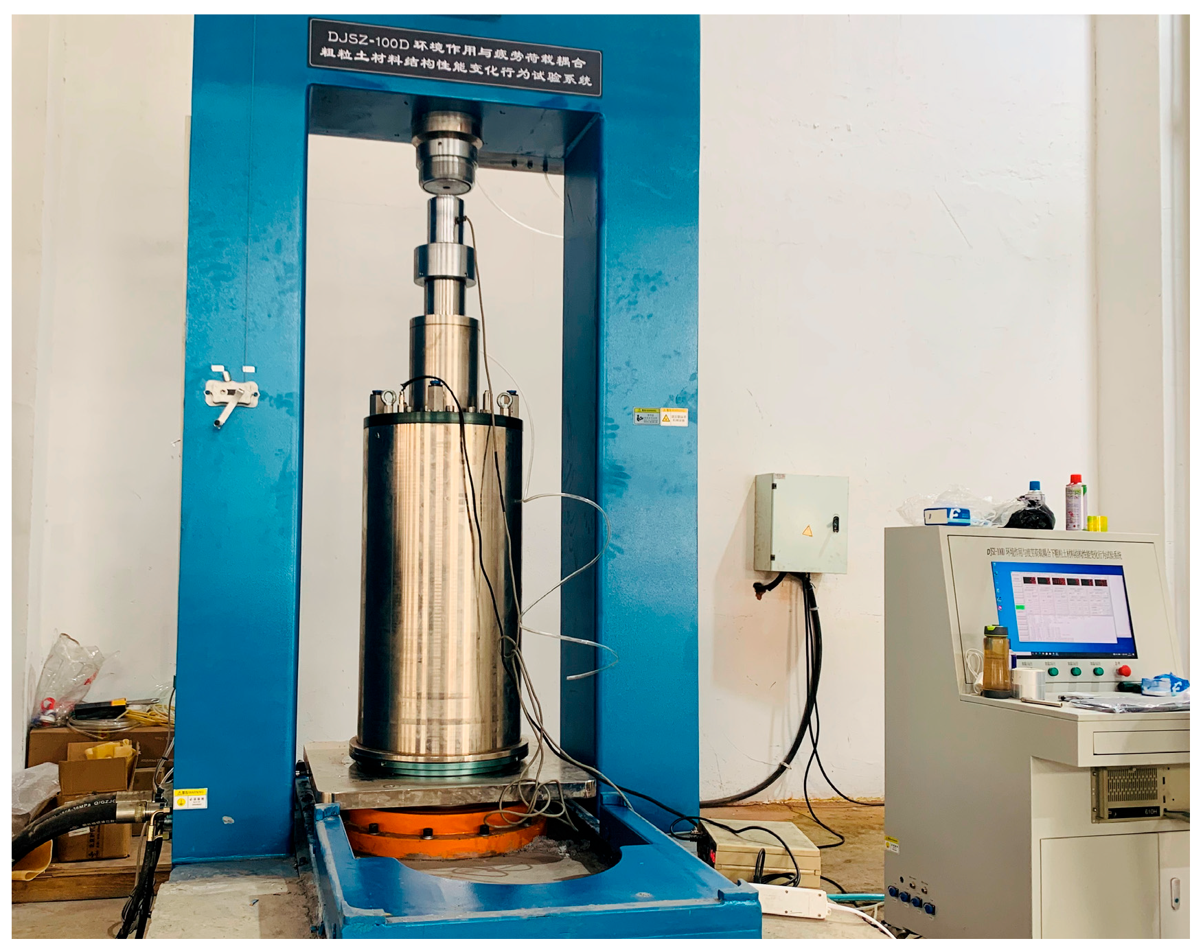
2.3. Static Triaxial Test

This study first determined the shear strength of silt-based foamed concrete through triaxial compression tests. The test procedure was designed with reference to Test Methods of Soils for Highway Engineering (JTG 3430-2020) [28]. The tests were conducted using the DJSZ-1000 testing system (as seen Figure 2), with sample dimensions of 150 mm (diameter) × 300 mm (height). The steps for the triaxial compression test are as follows: (1) The specimens, cured for 28 days, were placed on the instrument base and secured with rubber bands. The prepared specimens were then inserted into the pressure chamber, and water was injected to apply confining pressure uniformly during the test. (2) Confining pressures of 100 kPa, 200 kPa, and 300 kPa were applied to the pressure chamber. After the specified confining pressure was reached, axial compression was applied at a loading rate of 0.1 mm/s. (3) The test was stopped when the axial strain reached 10%, and experimental data, including axial load and displacement, were recorded for each test condition. The concrete had a 30% silt content and was tested at different wet densities: 600 kg/m3, 700 kg/m3, and 800 kg/m3. To ensure data reliability, three specimens were prepared for each test condition, and the results were presented as the average of the data.

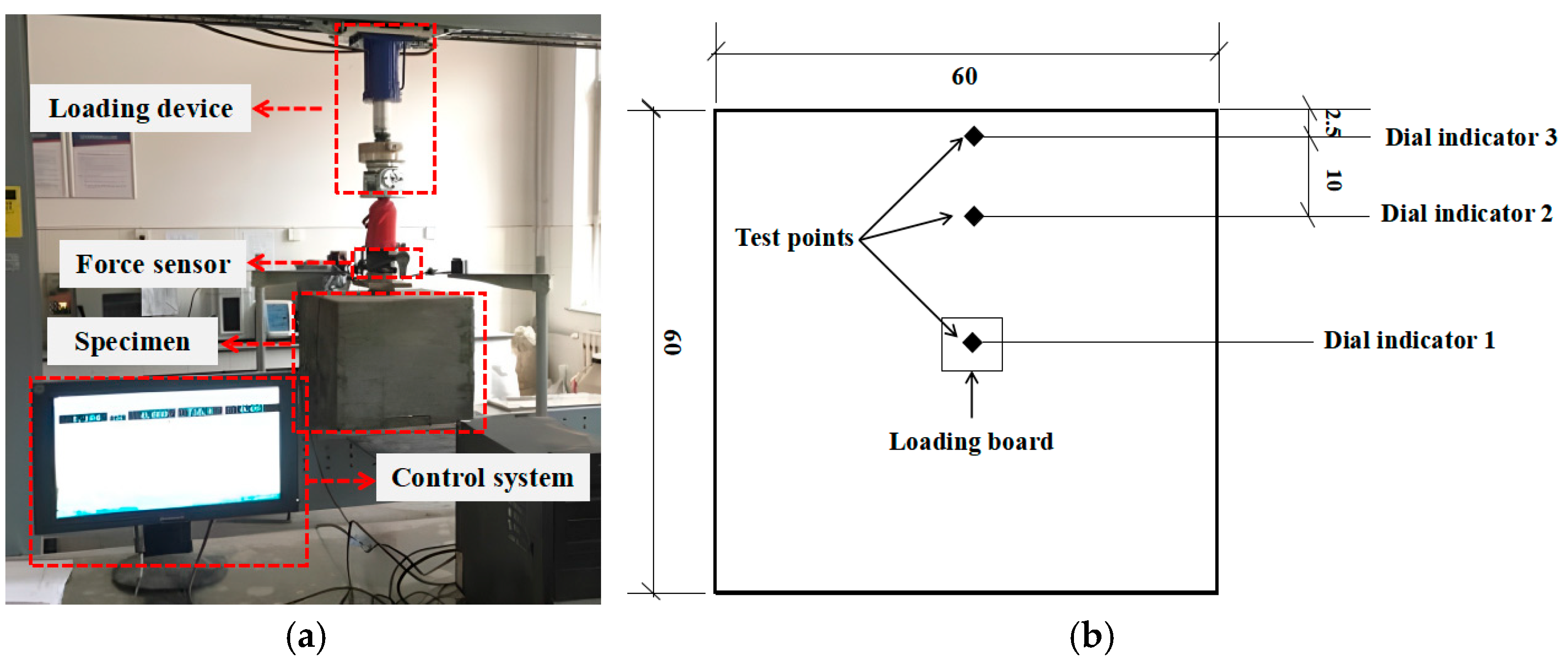
2.4. Local Loading on Foamed Concrete Foundation

Secondly, a local loading on large-size foamed concrete specimen was conducted to investigate the bearing capacity of the foamed concrete foundation. As no specific testing standard exists for this type of test, the setup was designed based on previous research [29] and practical engineering requirements. In this study, two different specimen sizes were used: cylindrical specimens with dimensions of 150 mm × 300 mm were adopted for standard mechanical tests (e.g., triaxial compression), while large cubic specimens with dimensions of 600 mm × 600 mm × 600 mm were prepared specifically for the localized bearing test to better simulate actual foundation conditions.
Figure 3a shows the diagram of the vertical bearing simulation test of silt-based foamed concrete. The foundation size is 600 mm × 600 mm × 600 mm, and a square steel plate with the size of 100 mm × 100 mm × 20 mm is used to apply the local loading. This steel plate is joint with a loading device and sensor, which can measure both the applied load and vertical displacement of the plate. Before the test, the unconfined compressive strength of the specimen is measured and divided into 10 levels. The test is conducted with a stepwise loading rate of 0.1 mm/s, with each stage lasting 2 min, until the design compressive strength is reached. If no failure occurs after 10 stages, the loading will continue until the specimen fails.
Displacement is monitored using dial gauges, and the load is measured with pressure sensors. The loading process is continuously monitored and recorded in real-time using a computer system, which tracks both the load magnitude and loading time. To ensure the accuracy of the test results, two dial gauges are used to monitor displacement, minimizing errors. Additionally, three different loading points are designed to investigate the effect of the distance from the loading location to the edge, as shown in Figure 3b. The distances of loading points 1, 2, and 3 from the edge were 2.5, 12.5, and 30 (center loading) cm, respectively.

3. Test Results and Discussion

3.1. Triaxial Compression of Silt-Based Foamed Concrete

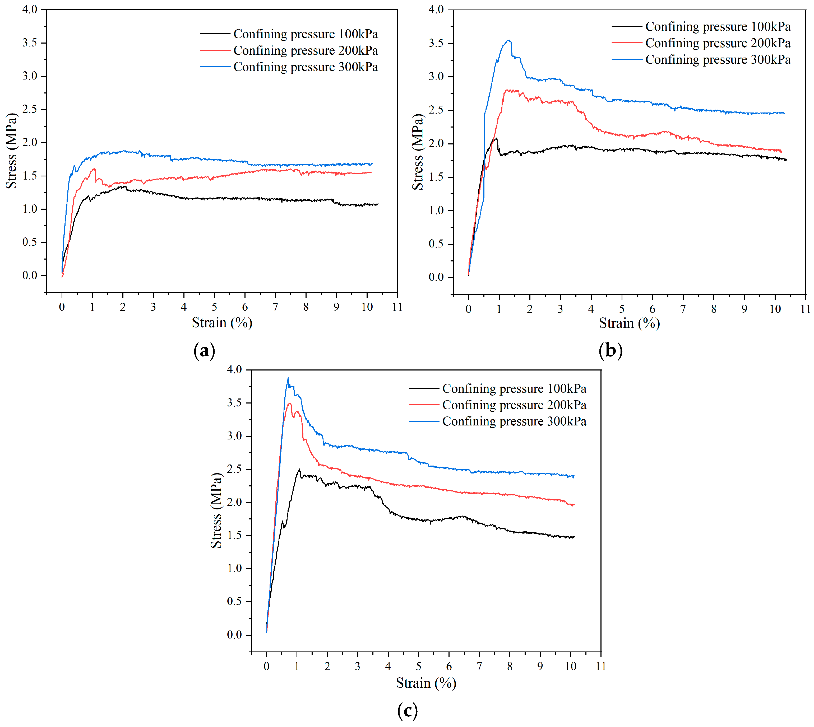
3.1.1. Stress–Strain Curves

Figure 4 presents the stress–strain curves of foamed concrete samples with different wet densities under triaxial tests. As shown, the stress–strain curves exhibit typical plastic deformation characteristics, undergoing three main stages: linear increase, peak failure, and post-peak plastic deformation [30]. During the initial loading phase, the stress increases linearly with strain, indicating that the material remains in the elastic deformation stage. As the stress approaches the peak value, microcracks begin to develop within the material, ultimately leading to failure at peak stress. At this stage, foamed concrete samples of different densities display distinct failure modes.
Figure 4 further reveals the significant effect of confining pressure on the mechanical behavior of foamed concrete. As the confining pressure increases, both the peak stress and the slope of the ascending section of the stress–strain curve increase significantly, indicating that a higher confining pressure effectively enhances strength and stiffness. This change primarily results from increased confinement of internal particles, leading to a more uniform contact stress distribution, delayed material yielding, and an enhanced load-bearing capacity. Additionally, confining pressure compresses the pore structure of foamed concrete, reducing the porosity, enhancing particle interactions, and improving both the strength and the deformation capacity.
High-density foamed concrete typically exhibits brittle shear failure, characterized by the formation of diagonal shear bands (as shown in Figure 5a) and a rapid decrease in stress after reaching peak stress. In contrast, low-density foamed concrete undergoes progressive compaction under load (as shown in Figure 5b), leading to a more gradual post-peak stress reduction due to its high porosity and energy absorption capacity. This suggests that the internal structure of lower-density foamed concrete allows for greater deformation adaptability under applied loads [13]. This finding aligns with the conclusions in references [31,32], which also demonstrated that due to the large number of pores inside foamed concrete, the specimen retains a high degree of integrity after yielding and does not experience obvious overall collapse.

3.1.2. Compression Strength and Strength Ratio

Figure 6 shows the 28-day unconfined compressive strength and triaxial static compression strength data of samples with different wet densities under different confining pressures. The triaxial compression strength of foamed concrete is positively correlated with both the wet density and the confining pressure. When the wet density increases from 600 kg/m3 to 800 kg/m3, the compression strength increases by 46.2%, 54.15%, and 51.8% for confining pressures of 100, 200, and 300 kPa, respectively. This improvement stems from the reduced porosity and the increased particle contact area at higher wet densities, which enhance inter-particle interactions and stress distribution, thereby improving the compressive strength. Zhang et al. [7] confirms this densification effect is particularly pronounced at higher wet densities.
Confining pressure also significantly impacts compression strength. For the 700 kg/m3 specimen, the compression strength approximately doubles as the confining pressure increases from 100 kPa to 300 kPa. A similar trend is observed for the 800 kg/m3 specimen, with its strength showing comparable improvement across the same confining pressure range. To quantify these effects, this study introduces the strength ratio (SR) for foamed concrete, defined as the ratio of the triaxial peak strength to the 28-day uniaxial unconfined compressive strength:
S R = f c , t r i a x i a l f c , u n i a x i a l
where fc,triaxial is the 28-day triaxial compression strength, and fc,uniaxial is the 28-day uniaxial compressive strength.
Figure 7 illustrates the strength ratio variation of specimens with different wet densities under varying confining pressures. As shown, low-density, silt-based foamed concrete exhibits a significant increase in the strength ratio with the confining pressure, indicating that higher porosity materials achieve a greater load-bearing capacity improvement under confinement. In contrast, high-density, silt-based foamed concrete shows a more gradual strength ratio increase. This is primarily due to its denser internal structure, where additional confining pressure provides limited compaction, resulting in a smaller constraint effect enhancement.
Although the 800 kg/m3 specimen exhibited higher absolute compressive strength, its strength ratio (SR) was slightly lower than that of the 700 kg/m3 specimen. This may be attributed to the fact that the 800 kg/m3 mix, while stronger, had lower deformability under confinement, leading to less relative strength gain. The 700 kg/m3 specimen maintained a better balance between compressibility and confinement response, which contributed to its higher SR. This result suggests that 700 kg/m3 may represent an optimal wet density for balancing mechanical performance and lightweight characteristics, offering sufficient strength gain without compromising deformation capacity or weight efficiency.

3.1.3. Shear Strength

By fitting the failure envelope under different confining pressures to the Mohr–Coulomb failure criterion, the cohesion (c) and internal friction angle ( φ ) of the material can be obtained. These parameters, commonly referred to as the shear strength index, characterize the material’s resistance to shear failure. The triaxial compression test results are shown in Table 4. These parameters are crucial for evaluating the stability and load-bearing capacity of silt-based foamed concrete in various engineering environments.
Figure 8 illustrates the shear strength parameters (c and φ ) of silt-based foamed concrete under triaxial (confined) conditions at different wet densities. The experimental results indicate that both cohesion and the internal friction angle increase significantly with the increasing wet density. Specifically, when the wet density increases from 600 kg/m3 to 800 kg/m3, the cohesion increases from 198.6 kPa to 413.7 kPa. This change is primarily due to the reduction in porosity and the enhanced bonding between particles, enabling the material to resist shear failure more effectively. Additionally, the internal friction angle shows a clear increasing trend, with internal friction angles of 43.2°, 50.7°, and 56.9° for silt-based foamed concrete under confined conditions with wet densities of 600 kg/m3, 700 kg/m3, and 800 kg/m3, respectively. This trend reflects the densification of the internal structure of silt-based foamed concrete as the wet density increases, with enhanced interlocking between particles, significantly improving the shear strength. As the wet density increases, the inter-particle interaction strengthens, and the shear deformation capacity of the material improves, leading to better stability and shear resistance in engineering applications.

3.2. Deformation and Bearing Capacity Under Different Loading Conditions

3.2.1. The Effect of the Wet Density

Figure 9 shows the load-displacement curves of silt-based foamed concrete at different loading points. As seen, the evolution of the load-displacement curves is similar at all loading points, with a slow initial increase followed by a sharp rise at the critical load, indicating that the material rapidly becomes unstable after reaching its ultimate bearing capacity. This critical load is defined as the foundation’s bearing capacity.
The curve trends indicate that the wet density has a significant impact on the bearing capacity and deformation characteristics of silt-based foamed concrete. As the wet density increases, the bearing capacity of the specimens gradually improves. Specifically, under the 800 kg/m3 condition, the specimen exhibits a higher peak load and smaller displacement change. In contrast, the 600 kg/m3 specimen experiences larger displacement at lower loads, with a rapid increase in displacement near the ultimate load, reflecting its weaker compressive strength and poorer structural stability. Marcin [33] also found in his research that with the increase of the density of foamed concrete, both the fracture energy and the maximum tensile stress of the foamed concrete increased. At different loading points, the displacement of the 600 kg/m3 specimen is significantly higher than that of the 700 kg/m3 and 800 kg/m3 specimens. Particularly under edge loading (Figure 9c), the 600 kg/m3 specimen experiences notable displacement at 0.3 MPa, and its settlement increases sharply before failure, indicating poor local stability. The 700 kg/m3 specimen shows the smallest displacement, demonstrating the best settlement control. Although the 800 kg/m3 specimen has higher compressive strength, its lower deformability and higher stiffness may lead to reduced energy absorption under localized loading, resulting in slightly higher settlement compared to the 700 kg/m3 specimen.

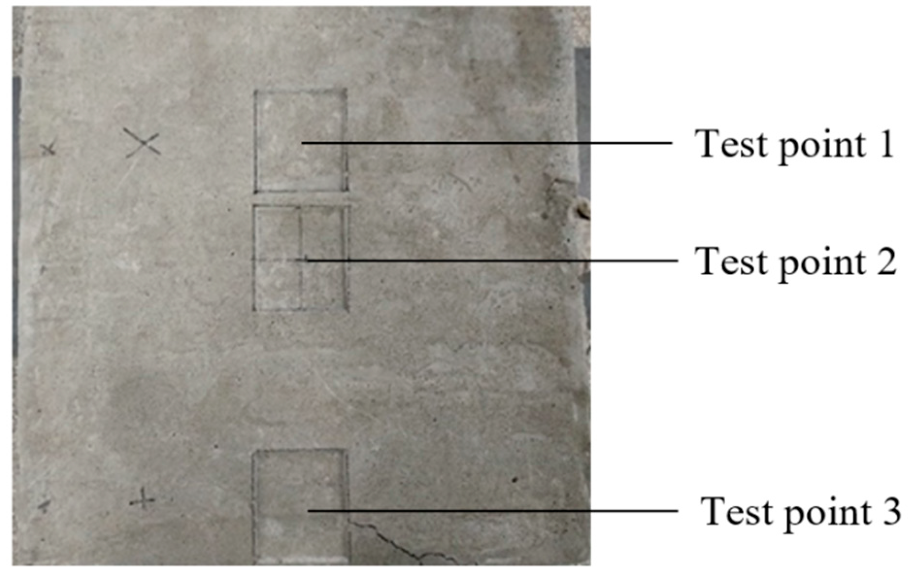
3.2.2. The Effect of Different Loading Points

Figure 10 shows the load-displacement curves of silt-based foamed concrete at different loading points with a wet density of 700 kg/m3. It showed the most balanced performance between strength and deformability and, therefore, is representative for analyzing the effect of loading position. It is evident that the loading position significantly affects the bearing capacity and displacement characteristics. Under central loading (test point 1), the specimen exhibits the highest ultimate bearing capacity of 2.35 MPa, with the smallest displacement at failure, measuring 3.7 mm. Under eccentric loading (test point 2), the ultimate bearing capacity is slightly lower at 2.26 MPa, and the displacement at failure increases to 5.3 mm. In contrast, under edge loading (test point 3), the specimen shows the lowest bearing capacity of 1.79 MPa, and the displacement increases more rapidly, especially at higher load levels, with the failure displacement reaching 7.13 mm. This difference is mainly due to uneven stress distribution. Under central and eccentric loading, the specimen experiences more uniform stress, resulting in smoother deformation. However, under edge loading, the stress concentration effect is more pronounced, leading to increased deformation in localized areas, especially at higher load levels. The displacement at test point 3 increases most rapidly, indicating that under edge loading, localized shear failure is more likely to occur, causing the material to fail more quickly.
Figure 11 shows the failure surfaces at test points 1, 2, and 3 for the specimen with a wet density of 700 kg/m3, while Figure 12 presents the failure morphology in the edge loading area. A closer examination of the failure surfaces reveals no significant cracks around test points 1 and 2, but clear cracks appear at test point 3, extending towards the edge (Figure 11). In the edge loading area, the cracks extend downward from the edge and gradually propagate to the sides, eventually forming diagonal shear failure (Figure 12), with the maximum crack width measuring 2 mm. This indicates that when the confining ability around the silt-based foamed concrete decreases, the failure mode shifts from more uniform shear failure to more localized and intense failure.

4. Theoretical Analysis of Bearing Capacity

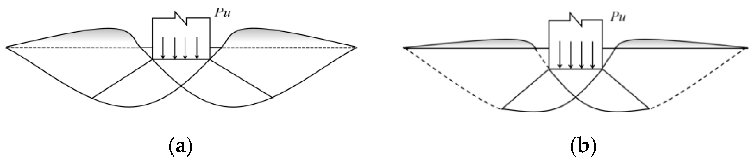
4.1. Typical Damage Models for Foundation Bearing Capacity

When soil foundation experiences bearing capacity failure due to increasing loading, it generally manifests as shear failure. Three primary patterns of shear failure are as follows: general shear failure, local shear failure, and punching shear failure, as shown in Figure 13. In the figure, the arrows indicate the direction of the applied loads, the dotted lines represent potential shear surfaces, and the different letters (a, b, c) correspond to distinct failure modes or curves as described in the figure caption.
The overall shear failure is shown by line a in Figure 13d, which has a clear turning point. Once the foundation reaches its ultimate bearing capacity, it experiences significant settlement and instability. Local shear failure, shown by line b, occurs in a small area without a turning point, caused by excessive deformation and settlement that lead to a loss of bearing capacity. Punching shear failure, represented by line c, also lacks a clear turning point.
Based on the experimental results and observations of foamed concrete foundation, for non-edge loading conditions, the load-displacement curve of silt-based foamed concrete shows a clear turning point but no bulging phenomenon. Its failure mode is more similar to local shear failure. For edge loading conditions, the failure mode of silt-based foamed concrete is more akin to direct shear failure. This paper focuses on constructing the ultimate bearing capacity formula for silt-based foamed concrete under edge loading conditions.

4.2. Theoretical Formulation of Silt-Based Foamed Concrete Ultimate Bearing Capacity

Based on the contact conditions between the bearing plate and silt-based foamed concrete, assuming the base of the loading plate is completely rough and following the local shear failure mode, the calculation is performed by adapting Terzaghi’s bearing capacity theory, as shown in Figure 14. The theoretical expression is given in Equation (2). Equations (3)–(5) are functions of ϕ , in which the parameter N γ is not explicitly defined in the Terzaghi theory. Therefore, this paper adopts the expression of N γ proposed in the study by Hansen [34], which serves as the basis for the calculation.
P u = 1 2 γ b N γ + q N q + c N c
N q = e ( 3 π 2 ϕ ) tan ϕ 2 cos ( 45 ° + ϕ 2 )
N c = N q 1 cot ϕ
N γ = 1.8 N q 1 tan ϕ
where Pu is the ultimate bearing capacity, kPa; b is foundation width, m; γ is soil unit weight, kN/m3; N q , N c , and N γ are bearing capacity factors for a rough foundation; q is the overburden stress, kPa; c is the cohesion within the foundation soil, kPa.
Since foamed concrete differs from soil foundations, it is initially considered that it conforms to the general form of Terzaghi’s bearing capacity equation, with necessary correction factors. For local shear failure, the shear strength parameters require adjustment. According to Wen [35], the corrected cohesion and friction angle are defined as Equations (6) and (7).
c * = 2 / 3 c
ϕ * = arctan [ ( 2 tan ϕ / 3 ) ]
By substituting the corrected ϕ * into Equations (3)–(5), the corrected expressions for N q , N c , and N γ are obtained, as shown in Equation (8).
P u = A γ b N γ + q N q + B c * N c
where A and B are empirical coefficients.
Based on the aforementioned experimental results, the reliability of the formula was verified, and empirical coefficients A and B were obtained through a regression analysis. The bearing plate has a width of b = 0.1 m and an embedment depth of d = 0 m. The shear strength parameters were acquired from Section 3.1.3. The coefficients, A = 31.04 and B = –0.07, were obtained by nonlinear least-squares regression using MATLAB (R2021a), minimizing the difference between the measured and the predicted ultimate bearing capacities across all the density groups, based on Equation (8). According to Equation (8) and Table 5 (30% silt content), the ultimate bearing capacity for silt-based foamed concrete can thus be calculated using the following formula:
P u = 31.04 γ b N r + q N q 0.07 c * N c
According to the theoretical Formula (9) and the experimental results in Section 3.2, the comparison between the predicted and the measured bearing capacities of silt-based foamed concrete is shown in Figure 15.
As can be seen, the difference between the predicted bearing capacity from the theoretical formula and the measured values is small, with the relative error remaining within 3%, which is considered an acceptable range in geotechnical practice [36]. This indicates that the theoretical formula can accurately predict the bearing capacity of foamed concrete, thus validating the reliability of the proposed bearing capacity calculation method.
Furthermore, the observed deformation behavior of silt-based foamed concrete under vertical loading—characterized by basin-shaped settlement and localized failure—reflects the material’s porous and compressible nature. As the wet density increases, the internal structure becomes denser, and deformation becomes more confined. This trend aligns with the increase in the ultimate bearing capacity predicted by Terzaghi’s theory, confirming that the material’s deformation behavior is directly related to its stiffness and the confinement effect, which are captured in the theoretical model. Nevertheless, the theoretical approach is most applicable to the short-term, vertically loaded conditions studied here. Broader applications may require further refinement to account for time-dependent behavior and large-scale effects.

5. Conclusions

To investigate the bearing characteristics and deformation behavior of silt-based foamed concrete under vertical loading, this study conducted subgrade bearing capacity model tests on silt-based foamed concrete with wet densities of 600 kg/m3, 700 kg/m3, and 800 kg/m3 and a silt content of 30%. The analysis of the experimental results yielded the following main conclusions:
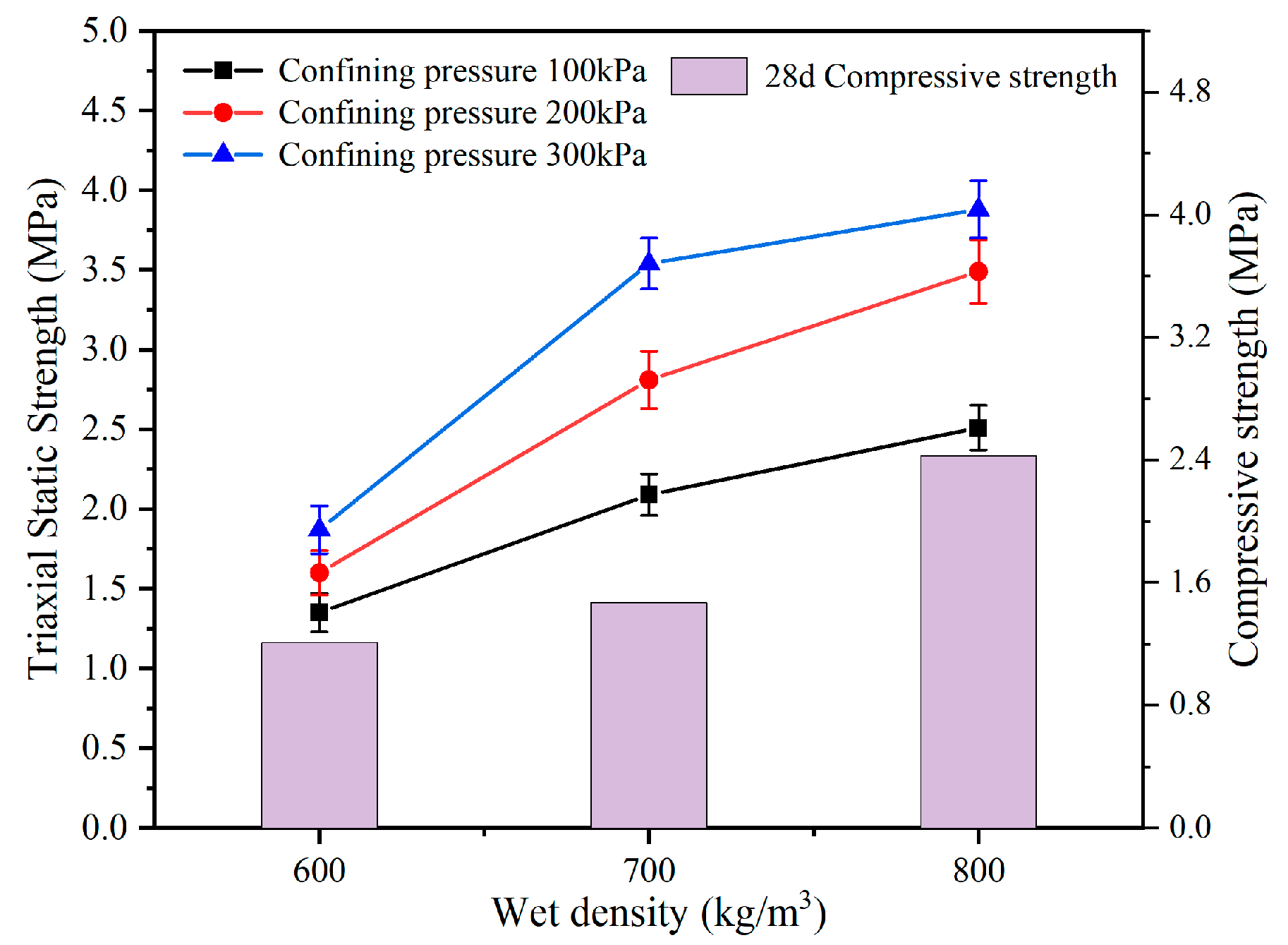
  • As the wet density increased from 600 kg/m3 to 800 kg/m3, the 28-day compressive strength rose from 1.21 MPa to 2.43 MPa, and the triaxial shear strength under 300 kPa confinement increased from 1.87 MPa to 3.88 MPa. This improvement is mainly attributed to reduced porosity and enhanced particle bonding, which increased the material’s load-bearing capacity and deformation resistance.
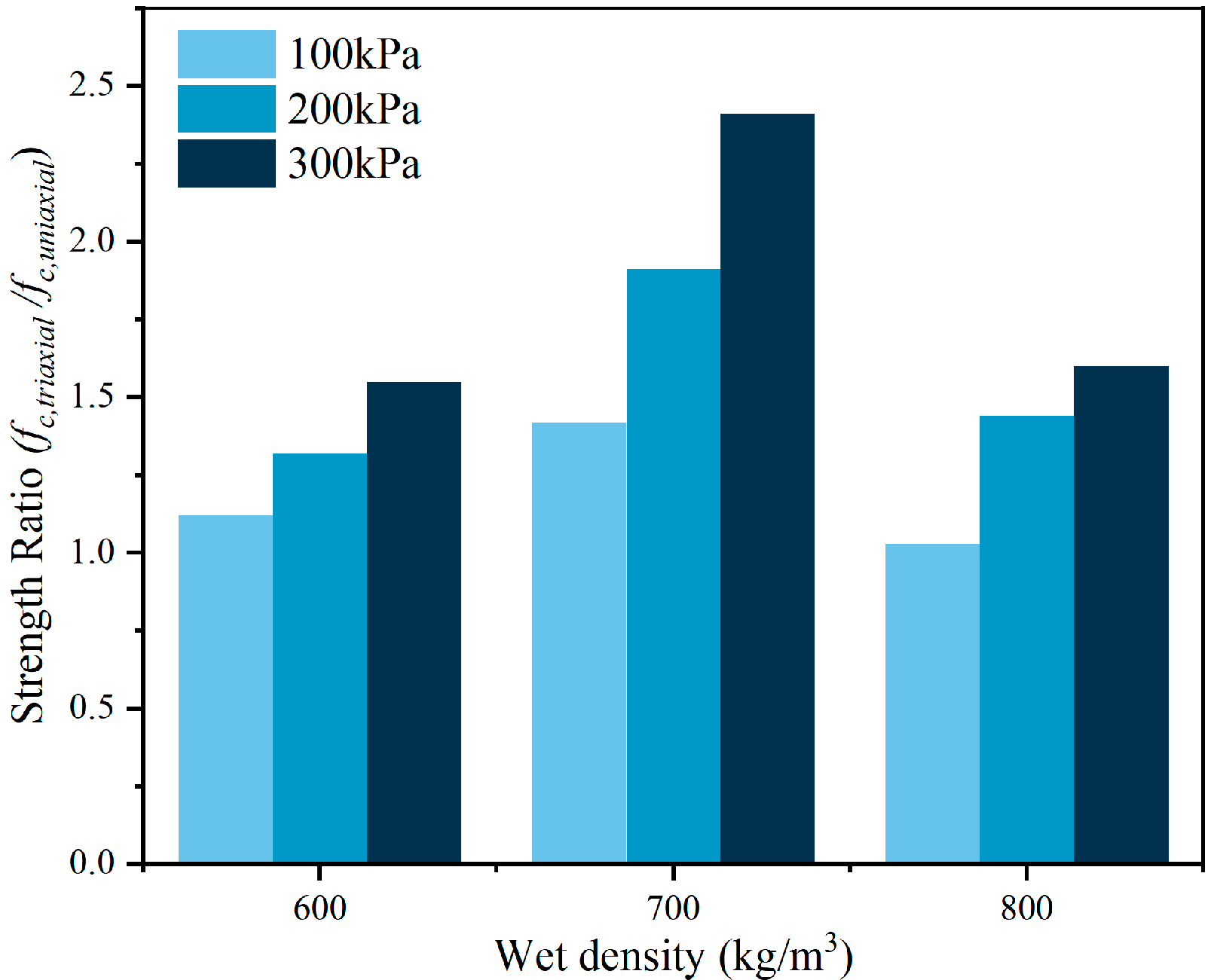
  • The compression of the pore structure improved the particle contact and the load transfer, leading to a significant increase in the strength ratio under confinement. Notably, although the 800 kg/m3 specimen exhibited higher compressive strength, the 700 kg/m3 group showed a maximum strength ratio of 2.41, exceeding that of the 800 kg/m3 group (1.6), due to its better deformability and confinement response.
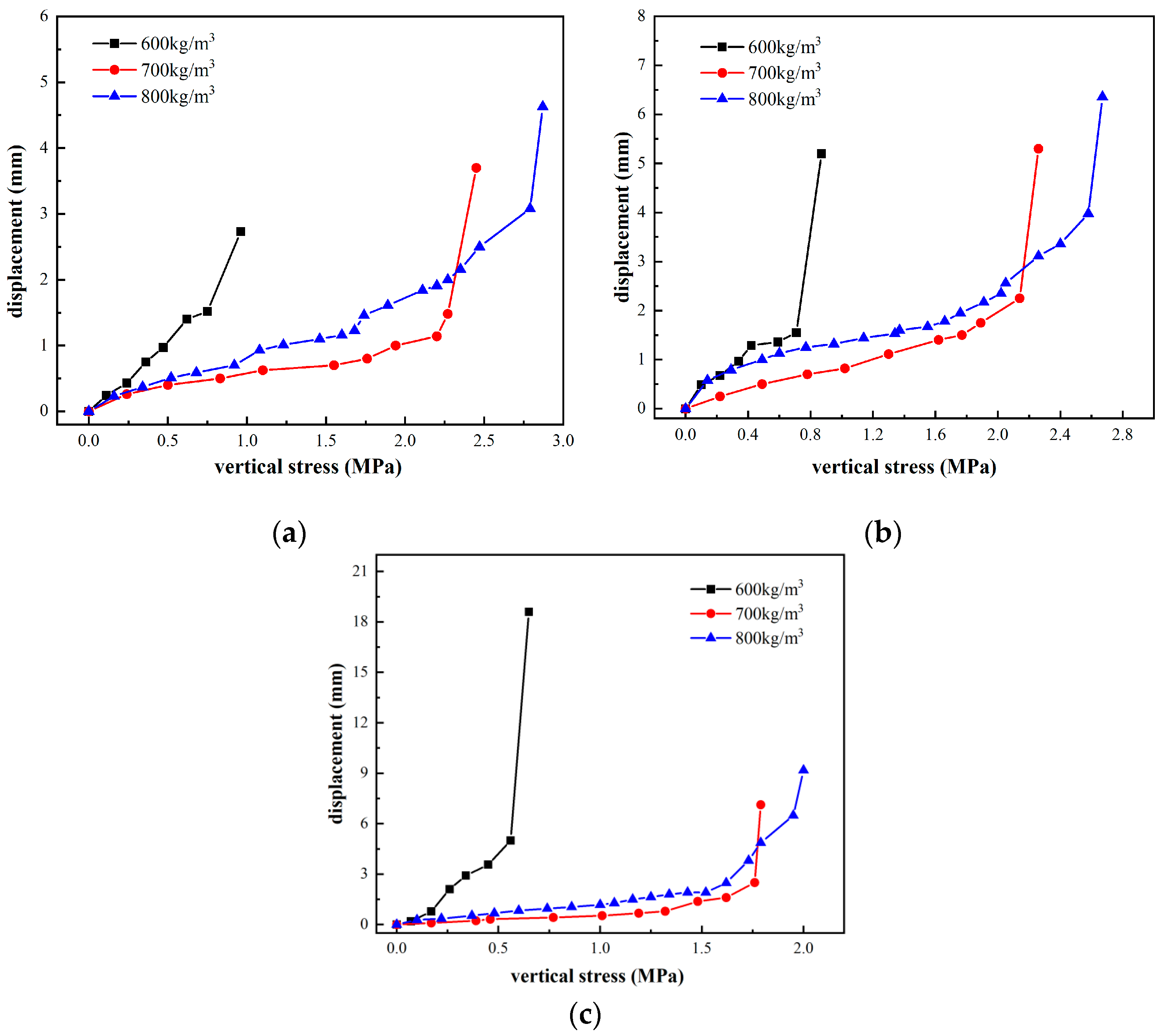
  • When subjected to vertical loads, silt-based foamed concrete exhibits a basin-shaped deformation pattern similar to that of a foundation, and the higher the density of the silt-based foamed concrete, the stronger its deformation resistance.
  • Under non-edge loading conditions, the failure mode is closer to local shear failure; under edge loading conditions, the failure mode of silt-based foamed concrete more closely resembles direct shear failure.
  • Based on the results of model tests and building upon Terzaghi’s bearing capacity theory formula, this study developed a calculation formula for the ultimate bearing capacity applicable to silt-based foamed concrete with a 30% content. The formula showed good agreement with measured values, with the relative errors within 3%, confirming the formula’s reliability.
  • For engineering applications, a wet density of around 700 kg/m3 is recommended to balance strength and lightweight requirements. Engineers should also consider loading position effects, as edge loading may lead to more severe failure. These findings provide practical guidance for the use of silt-based foamed concrete in shallow foundations and embankments.
  • This study investigated the triaxial mechanical behavior, deformation characteristics, and bearing capacity of silt-based foamed concrete under vertical loading. Based on experimental data and Terzaghi’s theory, a calculation formula for ultimate bearing capacity was developed, showing good agreement with measured results (relative errors within 3%). The observed shear failure modes and load–deformation behavior provide insights for shallow foundation design and failure prediction. The proposed formula is applicable to silt-based foamed concrete with a 30% silt content and wet densities of 600–800 kg/m3 under short-term loading. However, its accuracy may be limited under extreme environmental conditions, long-term loads, or outside the tested density range. Future work should investigate durability-related performance and explore microstructural evolution using techniques such as micro-CT and digital imaging.

Author Contributions

Conceptualization, C.M.; Methodology, J.W. and N.Z.; Software, C.W.; Validation, J.W. and N.Z.; Formal analysis, N.Z. and S.Z.; Investigation, Y.T.; Resources, C.W. and Q.S.; Data curation, Q.S. and X.R.; Writing—original draft, C.M., S.Z. and Y.T.; Writing—review & editing, J.W. and S.L.; Visualization, S.Z.; Project administration, C.M., S.L. and X.R.; Funding acquisition, H.Z. All authors have read and agreed to the published version of the manuscript.

Funding

This research was supported by the National Key Research and Development Program of China (Grant No. 2022YFB2602102). The APC was funded by Shandong High-Speed Group Co., Ltd.

Data Availability Statement

The original contributions presented in this study are included in the article. Further inquiries can be directed to the corresponding author.

Acknowledgments

The research reported in this paper is supported by Shandong High-Speed Group Co., Ltd. The authors gratefully acknowledge their financial support.

Conflicts of Interest

Authors Ning Zhang and Shengtao Zhang were employed by the company Shandong High-Speed Group Co., Ltd. Authors Shurong Lou and Xianfu Ren were employed by the company Shandong High-Speed Weifang Development Co., Ltd. The remaining authors declare that the research was conducted in the absence of any commercial or financial relationships that could be construed as a potential conflict of interest. The sponsors had no role in the design, execution, interpretation, or writing of the study.

References

  1. Amran, Y.H.M.; Farzadnia, N.; Abang Ali, A.A. Properties and applications of foamed concrete: A review. Constr. Build. Mater. 2015, 101, 990–1005. [Google Scholar] [CrossRef]
  2. Zhang, H.; Wang, J.; Wang, C.; Liu, M.; Wu, J. Using Foamed Concrete Layer to Optimize the Design of Pavement and Subgrade Structures: From the Perspectives Economy and Durability. Arab. J. Sci. Eng. 2023, 48, 12859–12874. [Google Scholar] [CrossRef]
  3. Zhang, H.; Wang, J.; Liu, Z.; Ma, C.; Song, Z.; Cui, F.; Wu, J.; Song, X. Strength characteristics of foamed concrete under coupling effect of constant compressive loading and freeze-thaw cycles. Constr. Build. Mater. 2024, 411, 134565. [Google Scholar] [CrossRef]
  4. Jusi, U.; Dhamrodji, P.; Maizir, H. Foam Mortar Layer in Soft Subgrade Embankment: A Review. IOP Conf. Ser. Earth Environ. Sci. 2024, 1321, 012040. [Google Scholar] [CrossRef]
  5. Gencel, O.; Kazmi, S.M.S.; Munir, M.J.; Kaplan, G.; Bayraktar, O.Y.; Yarar, D.O.; Karimipour, A.; Ahmad, M.R. Influence of bottom ash and polypropylene fibers on the physico-mechanical, durability and thermal performance of foam concrete: An experimental investigation. Constr. Build. Mater. 2021, 306, 124887. [Google Scholar] [CrossRef]
  6. Wu, J.; Wang, J.; Liu, M.; Zhuang, P.; Zhang, H.; Song, X. Dynamic Properties of Silt-Based Foamed Concrete as Filler in Subgrade. J. Mater. Civ. Eng. 2022, 34, 04022241. [Google Scholar] [CrossRef]
  7. Zhang, H.; Liu, M.; Yu, J.; Sun, Y.; Zhou, P.; Song, J.; Song, X. Mechanical and Physical Properties of Silt-Based Foamed Concrete with Different Silt Types. Arab. J. Sci. Eng. 2022, 47, 12803–12815. [Google Scholar] [CrossRef]
  8. Zhao, W.; Su, Q.; Wang, W.; Niu, L.; Liu, T. Experimental Study on the Effect of Water on the Properties of Cast In Situ Foamed Concrete. Adv. Mater. Sci. Eng. 2018, 2018, 7130465. [Google Scholar] [CrossRef]
  9. Zhou, S.E.; Lu, Z.Y.; Jiao, L.; Li, S.X. Compression property and compression strength model of foamed concrete. J. Wuhan Univ. Technol. 2010, 32, 9–13. [Google Scholar] [CrossRef]
  10. Jiang, S.; Wang, L.; Feng, K. Compound modified experiment of protein-concrete foaming agent. Gongneng Cailiao/J. Funct. Mater. 2015, 46, 09056–09061. [Google Scholar]
  11. Harith, I.K. Study on polyurethane foamed concrete for use in structural applications. Case Stud. Constr. Mater. 2018, 8, 79–86. [Google Scholar] [CrossRef]
  12. Bin, R.; Li, J.; Gan, Y.; Huang, J. Mesoscopic simulation of the mechanical behaviour of foam concrete subjected to large compressive deformation. Constr. Build. Mater. 2024, 418, 135367. [Google Scholar] [CrossRef]
  13. Liu, M.; Wang, J.; Wang, C.; Liu, Z.; Zhang, H.; He, F. Stress-Solid Materials-Voids interaction of foamed concrete in isotropic compression. Constr. Build. Mater. 2022, 358, 129468. [Google Scholar] [CrossRef]
  14. Tan, X.; Chen, W.; Liu, H.; Chan, A.H.C. Stress-Strain Characteristics of Foamed Concrete Subjected to Large Deformation under Uniaxial and Triaxial Compressive Loading. J. Mater. Civ. Eng. 2018, 30, 04018095. [Google Scholar] [CrossRef]
  15. Su, B.; Zhou, Z.; Li, Z.; Wang, Z.; Shu, X. Experimental investigation on the mechanical behavior of foamed concrete under uniaxial and triaxial loading. Constr. Build. Mater. 2019, 209, 41–51. [Google Scholar] [CrossRef]
  16. Shi, X.; Huang, J.; Su, Q. Experimental and numerical analyses of lightweight foamed concrete as filler for widening embankment. Constr. Build. Mater. 2020, 250, 118897. [Google Scholar] [CrossRef]
  17. Luo, X.; Xu, J.-Y.; Liu, Y. The static constitutive model of fiber reinforced cellular materials. Constr. Build. Mater. 2018, 187, 903–906. [Google Scholar] [CrossRef]
  18. Guo, H.; Guo, W.; Shi, Y. Computational modeling of the mechanical response of lightweight foamed concrete over a wide range of temperatures and strain rates. Constr. Build. Mater. 2015, 96, 622–631. [Google Scholar] [CrossRef]
  19. Liu, M.P.; Zhang, H.B.; Lv, B.; Du, C.; Wang, J. Investigation on the yield and failure criterion of foamed concrete. J. Build. Eng. 2024, 84, 108604. [Google Scholar] [CrossRef]
  20. He, Y.; Gao, M.; Zhao, H.; Zhao, Y. Behaviour of Foam Concrete under Impact Loading Based on SHPB Experiments. Shock. Vib. 2019, 2019, 2065845. [Google Scholar] [CrossRef]
  21. Ni, F.M.-W.; Oyeyi, A.G.; Tighe, S. Structural capacity evaluation of lightweight cellular concrete for flexible pavement subbase. Road Mater. Pavement Des. 2021, 23, 2781–2797. [Google Scholar] [CrossRef]
  22. Chun, B.S.; Lim, H.S.; Shin, Y.W. Application of constitutive model to predict the behavior of EPS-geofoam. Geetechnical Eng. 2001, 5, 175–183. [Google Scholar] [CrossRef]
  23. GB 175-2007; Common Portland Cement. Standard Press of China: Beijing, China, 2007.
  24. GBT 50123-2019; Standard for Soil Test Methods. China Architecture & Building Press: Beijing, China, 2019.
  25. Zhang, H.B.; Liu, M.P.; Shuo, Z.; Zhao, Z.; Sun, Y.; Song, X.; Wang, H.; Zhang, X.; Wu, J. An experimental investigation of the triaxial shear behaviors of silt-based foamed concrete. Case Stud. Constr. Mater. 2021, 15, e00713. [Google Scholar] [CrossRef]
  26. Zhang, S.; Liu, M.P.; Wang, C.A.; Zhang, H.; Zhao, Z.; Wu, J. Compression, Unloading-reloading, and tension mechanical behaviors of Silt-based foamed concrete under uniaxial loading. Constr. Build. Mater. 2022, 347, 128558. [Google Scholar] [CrossRef]
  27. GB/T 11969-2020; Test Methods of Autoclaved Aerated Concrete. Ministry of Industry and Information Technology: Beijing, China, 2013.
  28. JTG 3430-2020; Test Methods of Soils for Highway Engineering. China Communications Press: Beijing, China, 2020.
  29. Huang, J.; Cai, D.; Su, Q.; Yao, H.; Fan, R.; Pei, Y.; Zhang, Z.; Yao, Y.; Luo, J.; Ou, X. Comparative study on static and dynamic characteristics of foamed concrete interlayer-type and traditional layered ballastless track subgrades. Constr. Build. Mater. 2025, 470, 140651. [Google Scholar] [CrossRef]
  30. Liu, M.P.; Liu, Z.K.; Wang, K.; Ma, C.; Zhang, H.; Zhuang, P. Strength and deformation performances of silt-based foamed concrete under triaxial shear loading. J. Build. Eng. 2022, 60, 105237. [Google Scholar] [CrossRef]
  31. Zhao, W.; Chen, W.Z.; Tan, X.J.; Huang, S. High-performance foam concrete for seismic-isolation materials of tunnels. Chin. J. Geotech. Eng. 2013, 35, 1544–1552. [Google Scholar]
  32. Chen, W.; Tian, H.; Yang, F.; Geng, Y. Study of effects of foam concrete preset deformation layer on long-term stability of deep soft rock tunnel. Rock Soil Mech. 2011, 32, 2577–2583. [Google Scholar]
  33. Kozłowski, M.; Kadela, M.; Kukiełka, A. Fracture Energy of Foamed Concrete Based on Three-Point Bending Test on Notched Beams. Procedia Eng. 2015, 108, 349–354. [Google Scholar] [CrossRef]
  34. Hansen, J.B. A General Formula for Bearing Capacity; Danish Geotechnical Institute: Copenhagen, Denmark, 1961. [Google Scholar]
  35. Fan, W.; Bai, X.Y.; Yu, M.H. Formula of ultimate bearing capacity of shallow foundation based on unified strength theory. Rock Soil Mech. 2005, 26, 1616–1621. [Google Scholar]
  36. Bowles, J.E. Foundation Analysis and Design, 3rd ed.; McGraw-Hill: New York, NY, USA, 1996. [Google Scholar]
Figure 1. Grading curve of silt soil.
Buildings 15 01914 g001
Figure 2. DJSZ-1000 static triaxial testing system.
Buildings 15 01914 g002
Figure 3. Loading scheme of silt-based foamed concrete foundation. (a) Loading schematic diagram; (b) top view of different loading locations on specimens (Unit: cm).
Buildings 15 01914 g003
Figure 4. Stress–strain curves under different confining pressures: (a) 600 kg/m3, (b) 700 kg/m3, (c) 800 kg/m3.
Buildings 15 01914 g004
Figure 5. Failure pattern of samples. (a) High density; (b) low density.
Buildings 15 01914 g005
Figure 6. Compression strength of samples with different wet densities.
Buildings 15 01914 g006
Figure 7. Strength ratio variation with confining pressure for different wet densities.
Buildings 15 01914 g007
Figure 8. Shear strength of silt-based foamed concrete at different wet densities. (a) Cohesion; (b) angle of internal friction.
Buildings 15 01914 g008
Figure 9. Load-displacement curves of silt-based foamed concrete at different test points. (a) Test point 1; (b) test point 2; (c) test point 3.
Buildings 15 01914 g009
Figure 10. Load-displacement curves of silt-based foamed concrete specimens at different test points.
Buildings 15 01914 g010
Figure 11. Failure surface of loading points 1, 2, and 3.
Buildings 15 01914 g011
Figure 12. Failure state from different view plan at loading point 3. (a) Top view; (b) front view.
Buildings 15 01914 g012
Figure 13. Three typical failure modes of foundation bearing capacity. (a) General shear failure; (b) local shear failure; (c) punching shear failure; (d) P–S curves corresponding to different failure modes.
Buildings 15 01914 g013aBuildings 15 01914 g013b
Figure 14. Calculation model of bearing capacity of Terzaghi foundation (completely rough foundation bottom).
Buildings 15 01914 g014
Figure 15. Measured value vs. predicted value.
Buildings 15 01914 g015
Table 1. Details of materials and equipment.
Specific Surface Area (m2/kg)Standard
Consistency (%)
Setting Time (min)Compressive Strength (MPa)Flexural Strength (MPa)
InitialFinal3 d28 d3 d28 d
35.828.219223128.150.76.59.6
Note: d = day.
Table 2. Foaming agent properties.
Foam Expansion Ratio1 h Settlement
Distance (mm)
1 h Bleeding Rate (%)Sedimentation Rate of Slurry (%)Solid Content (%)pHDensity (kg/m3)
24520223.47.21000
Note: Foam expansion ratio is dimensionless, expressed as the ratio of foam volume to liquid volume.
Table 3. Foamed concrete material proportion.
Wet Density (kg/m3)Silt Content (%)Mixture Composition (per m3)
Water (kg)Cement (kg)Silt (kg)Foam (kg)
60030157.98287.24123.1031.678
700186.70339.46145.4828.347
800215.43391.69167.8725.016
Table 4. Results of the triaxial compression strength test.
Wet Density (kg/m3) σ 1 (kPa) σ 3 (kPa) σ 1 σ 3 (kPa)Shear Strength Index
c (kPa) φ (°)
60013501001250198.643.2
16002001400
18703001570
70020901001990347.650.7
28102002610
35403003240
80025101002410413.756.9
34902003290
38803003580
Table 5. Calculation parameters of silt-based foamed concrete bearing capacity (30% silt content).
ParameterDensity (kg/m3)
600700800
Internal cohesion c (kPa)199348417
Internal friction angle φ (°)43.250.756.9
Unit weight γ (kN/m3)5.896.877.85
Foundation bearing capacity factor N c 72.4545.1427.11
N q 69.0456.1542.59
N γ 115.0121.28114.84
Measured ultimate bearing capacity P u (kPa)112015802040
Disclaimer/Publisher’s Note: The statements, opinions and data contained in all publications are solely those of the individual author(s) and contributor(s) and not of MDPI and/or the editor(s). MDPI and/or the editor(s) disclaim responsibility for any injury to people or property resulting from any ideas, methods, instructions or products referred to in the content.

