Article

TMD-Inerter for Tall Building Damping: Approximate Closed-Form Solution, Performance and Conclusions

Maurer Switzerland GmbH, Grossplatzstrasse 24, 8118 Pfaffhausen, Switzerland
Buildings 2025, 15(11), 1829; https://doi.org/10.3390/buildings15111829
Submission received: 17 April 2025 / Revised: 12 May 2025 / Accepted: 23 May 2025 / Published: 26 May 2025
(This article belongs to the Special Issue Vibration Monitoring and Control of the Built Environment)

Abstract

This paper analyzes the performance of the TMD-Inerter for tall building damping. The analysis is performed by simulation to ensure ideal working behaviour of the inerter, i.e., the inerter produces a force in proportion to the relative acceleration of its terminals without any friction of real inerter devices such as fly wheels. For the study, the most realistic TMD-Inerter configuration is considered where the inerter is grounded to the TMD mass and the structural mass next to the TMD mass, i.e., the TMD-Inerter is installed in the top floor room of the structure. Approximate closed-form solutions for the tuning of the TMD-Inerter parameters are derived based on the characteristics of the inerter force. The resulting frequency response functions for different inertance ratios are compared to those of the classical TMD with same mass ratio. The results clearly demonstrate that the TMD-Inerter worsens the tall building damping compared to the classical TMD for the realistic situation that the inerter is grounded to the structural mass next to the TMD. There are two physical reasons why the inerter worsens the efficiency of the TMD. First, the inerter force is per definition in proportion to the relative acceleration of its two terminals, i.e., it is not in proportion to the damper mass (absolute) acceleration whereby it does not increase the damper mass. Second, for harmonic excitation the inerter force characteristics show negative stiffness behaviour which explains why the TMD stiffness must be designed by taking into consideration both the TMD physical mass and the inertance to ensure the correct tuning of the TMD-Inerter natural frequency.

1. Introduction

The common method to mitigate wind-induced vibrations of tall buildings is to install a tuned mass damper (TMD) whose working behaviour and optimum tuning for minimum structural displacement response is well described by Den Hartog in his famous book “Mechanical Vibrations” [1]. For maximum efficiency, the TMD needs to be installed at the anti-node of the critical modal component, which is at the top of the building [2]. Typically, the pendulum mass of the TMD is between 0.5% to 1.5% of the modal mass of the dominant sway mode of the building. This may lead to fairly heavy TMD masses, often in the range of 300 t to 600 t, sometimes even heavier. To reduce such heavy pendulum masses, real-time controlled TMDs were developed, which require less pendulum mass because of their higher efficiency resulting from the frequency and damping real-time controls, e.g., see [3,4,5], which describe active and semi-active vibration absorber solutions. In recent years, the so-called TMD-Inerter (TMDI) has gained much attention. Per definition, the inerter produces a force being in proportion to the relative acceleration of its two terminals [6]. When the inerter is connected to the pendulum mass of the damper and to the floor of the damper room, it is therefore expected that the inerter “virtually” increases the damper mass without physical mass. So, the expectation is that the inerter could help to reduce the very big TMD masses, especially for high-rise building damping.
The damping performance of the TMDI was analyzed for various TMDI configurations, and analytical tunings of the natural frequency and damping ratio of the damper depending on the inertance of the inerter were proposed [6,7,8,9,10,11,12,13,14,15]. In the classical TMDI configuration, the inerter terminals are connected to the pendulum mass of the damper and the structural mass next to the damper without additional damping and stiffness elements [6,11]. This corresponds to the situation where the pendulum mass drives a fly wheel by a gear rod and the axle of the fly wheel is fixed to the floor of the TMD room as shown in, e.g., [15]. The TMDI configurations analyzed in [12,13,14] connect the inerter in series and parallel to dash pot and spring elements, which may be very difficult to realize without additional mechanical bearings producing undesirable friction. Other publications, e.g., [11], investigated the performance of the TMDI when the inerter is not grounded to the structure next to the damper but to the structure far away from the damper room or even to ground. A thorough overview of TMDI layout and performance investigations is provided in the review article [16].
Per definition, the inerter produces a force being in proportion to the relative acceleration of the two terminals of the inerter [6], i.e., the acceleration of the pendulum mass and the acceleration of the structural mass, e.g., the floor mass of the TMD room. The meaning is therefore that the inerter virtually increases the inertia of the TMD pendulum mass, i.e., as if the mass of the TMD pendulum was increased without adding mass. This idea must be questioned because the inerter force is—per definition—in proportion to the difference between TMD pendulum acceleration and structural acceleration, and hence, the inerter force is not an inertial force. Therefore, it is not correct to convey the message that the inerter produces an inertial force and virtually increases the TMD pendulum mass, i.e., without adding physical mass.
This article investigates this question. For this, the tall building is modelled by a multi degree-of-freedom (M-DOF) approach with TMDI on the top structural mass. The most realistic TMDI configuration is considered where the inerter is connected to the TMD pendulum mass and the top structural mass. For this system, an approximate TMDI tuning is derived. The resulting performance is compared to the performance of the classical TMD. The results demonstrate that the classical TMD outperforms the TMDI for any inertance ratio. The reason is the fact that the inerter force is not in proportion to the (absolute) acceleration of the TMD pendulum mass and therefore does not virtually increase the TMD pendulum mass. The fact that many publications conclude that the TMDI indeed virtually increases the pendulum mass seems to be caused by the assumption that the inerter can be grounded to earth. However, this is not feasible. The paper is structured as follows: Section 2 describes the modelling, Section 3 derives approximate tunings for the considered TMDI, Section 4 discusses the performance of the TMDI for various inertance ratios, and Section 5 summarizes the article and closes the article with concluding remarks.

2. Modelling

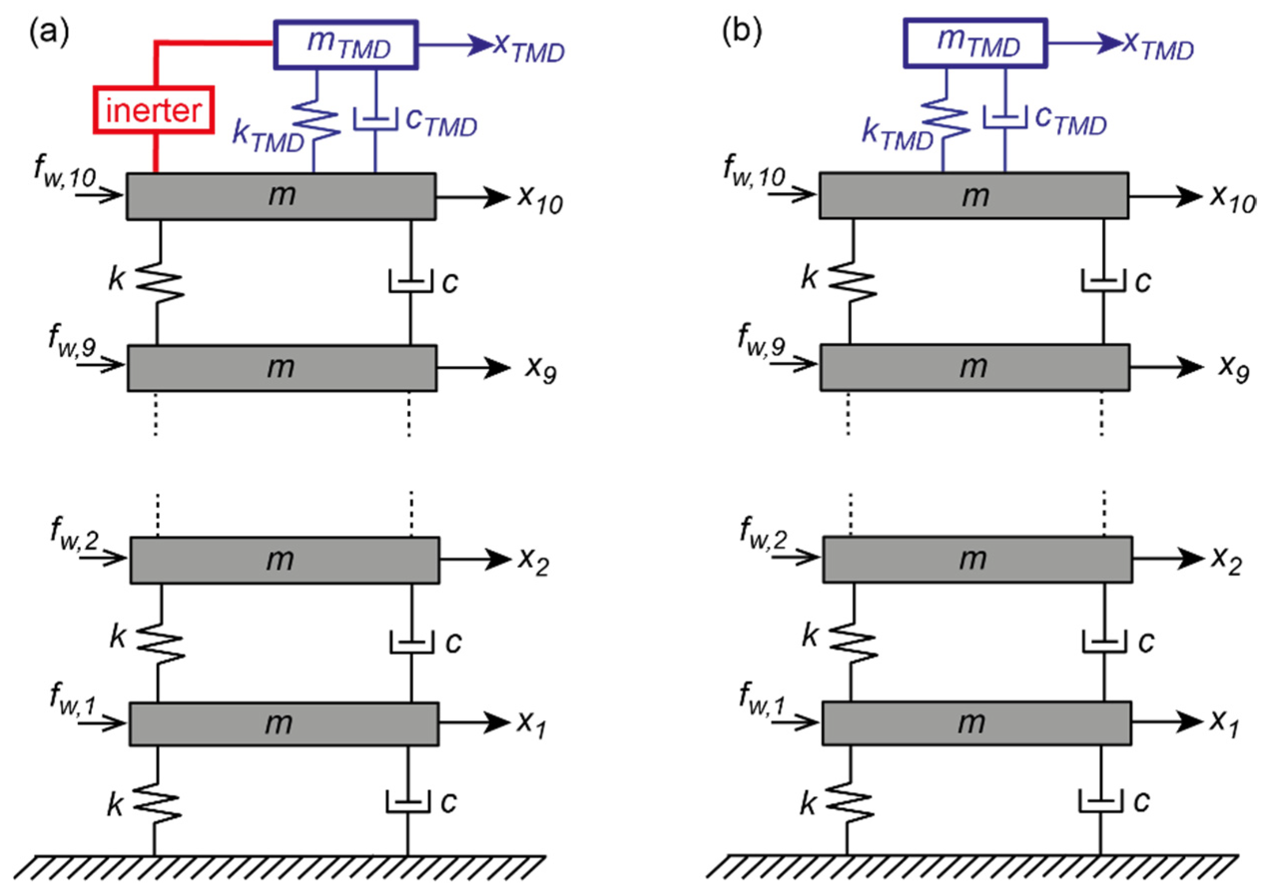
2.1. Model Structure of Tall Building with TMDI

The situation of a pendulum damper for tall building damping against wind excitation is best described by a M-DOF system with pendulum damper on the top structural mass with absolute displacement x 10 (see Figure 1a). The number of 10 DOFs simply means that the motion of the tall building is described by the 10 DOFs of the 10 lumped masses; it does not mean that the tall building consists of only 10 floors. Furthermore, the M-DOF system is assumed to be homogenous and linear to ensure the simplest structural model. The pendulum mass is connected to the top structural mass by the spring, with stiffness k T M D representing the cable support of the pendulum mass, and the dash pot with viscous damping coefficient c T M D representing the hydraulic damper and the inerter. Per definition, the inerter exerts a force in proportion to the relative acceleration of both inerter terminals. The most realistic TMDI configuration is when the inerter is connected to the TMD pendulum mass m T M D and grounded to the floor mass next to the TMD. For the building model under consideration, the inerter is therefore grounded to the structural mass m 10 , which yields the inerter force as follows:
f I = b x ¨ 10 x ¨ T M D
where b is the so-called inertance, which is given by the selected inertance ratio β as follows:
b = β   m 1
with m 1   being the modal mass of the first bending mode. As a benchmark, the same building model with classical TMD with the same mass ratio μ = m T M D / m 1   as the TMDI is simulated (see Figure 1b). So, the inertance ratio β relates the inertance b , which has the unit of mass, to the modal mass m 1 , similar to the mass ratio μ of the classical TMD, which relates the damper mass m T M D   to the modal mass m 1 .

2.2. Tall Building Model

The tall building is modelled by a homogenous, linear M-DOF system, i.e., each lumped mass has the same mass m , the same stiffness k , and the same viscous coefficient c . These structural parameters are selected such that the building model shows the typical values of tall buildings being susceptible to wind excitation (Table 1): the total mass is 50,000 t, the first bending mode modal mass is 25,000 t with associated eigenfrequency of 0.14 Hz, and the modal damping ratio is 1%. The considered damping ratio is the commonly assumed value for the one-year return period wind.

2.3. Equations of Motion

The primary structure is modelled as a linear, homogenous shear frame. The equations of motion of the the first two masses in the format of Newton’s second law are as follows:
x ¨ 1 = 1 m f w , 1 k   x 1 c   x ˙ 1 + k x 2 x 1 + c x ˙ 2 x ˙ 1
x ¨ 2 = 1 m f w , 2 k x 2 x 1 c x ˙ 2 x ˙ 1 + k x 3 x 2 + c x ˙ 3 x ˙ 2
where x j , x ˙ j   and x ¨ j denote the absolute displacement, velocity and acceleration of mass j , and f w , j describes the excitation force of mass j . The equations of motion of the storey masses 3 to 9 have the same format as for mass 2 (Equation (4)). The equation of motion of the top storey mass 10 is more interesting as it includes—besides the TMD stiffness force and TMD damping force—the inerter force as well:
x ¨ 10 = 1 m f w , 10 k x 10 x 9 c x ˙ 10 x ˙ 9 + k T M D x T M D x 10 + c T M D x ˙ T M D x ˙ 10 + b x ¨ T M D x ¨ 10
To solve this equation, the term b / m x ¨ 10 needs to be put on the left which leads to
x ¨ 10 = 1 m + b f w , 10 k x 10 x 9 c x ˙ 10 x ˙ 9 + k T M D x T M D x 10 + c T M D x ˙ T M D x ˙ 10 + b x ¨ T M D
The same procedure is performed for the TMD mass:
x ¨ T M D = 1 m T M D k T M D x T M D x 10 c T M D x ˙ T M D x ˙ 10 b x ¨ T M D x ¨ 10
x ¨ T M D = 1 m T M D + b k T M D x T M D x 10 c T M D x ˙ T M D x ˙ 10 + b x ¨ 10

2.4. Excitation

Wind excitation of tall buildings ranges from narrow to broadband type, commonly described as coloured noise. Despite this fact, the simulations are performed with harmonic excitation because this allows us to precisely assess the performance of the TMDI by the resulting steady-state response of the structure and damper. The excitation force amplitudes of the excitation forces f w , j with j = 1, …,10 are selected according to the mode shape of the first bending mode.

3. Approximate Tuning of TMDI and Resulting Performance

3.1. Den Hartog Tuning

Although it must be assumed that the Den Hartog formulae will lead to a suboptimal performance of the TMDI, these formulae are adopted first for the designs of the TMD natural frequency f T M D , TMD stiffness k T M D , TMD damping ratio ζ T M D and TMD viscous damping coefficient c T M D of the TMDI:
f T M D = f 1 1 + μ
ζ T M D = 3   μ 8   1 + μ 3
k T M D = m T M D 2   π   f T M D 2
c T M D = 2   ζ T M D   m T M D   2   π   f 1
Note that f 1 needs to be used Equation (12) because of the cubic exponent in Equation (10). The structural response and the damper relative motion x T M D x 10 are simulated for the mass ratio of 2% and inertance ratio of 2%. The structural response is plotted in Figure 2 by the displacement of the top mass divided by the ratio of the modal excitation force and stiffness to obtain the normalized displacement response. As expected, the normalized structural response due to the Den Hartog tuning is suboptimal. The shapes of this curve and the damper relative motion (Figure 3) are similar to those of a massively overdamped TMD.

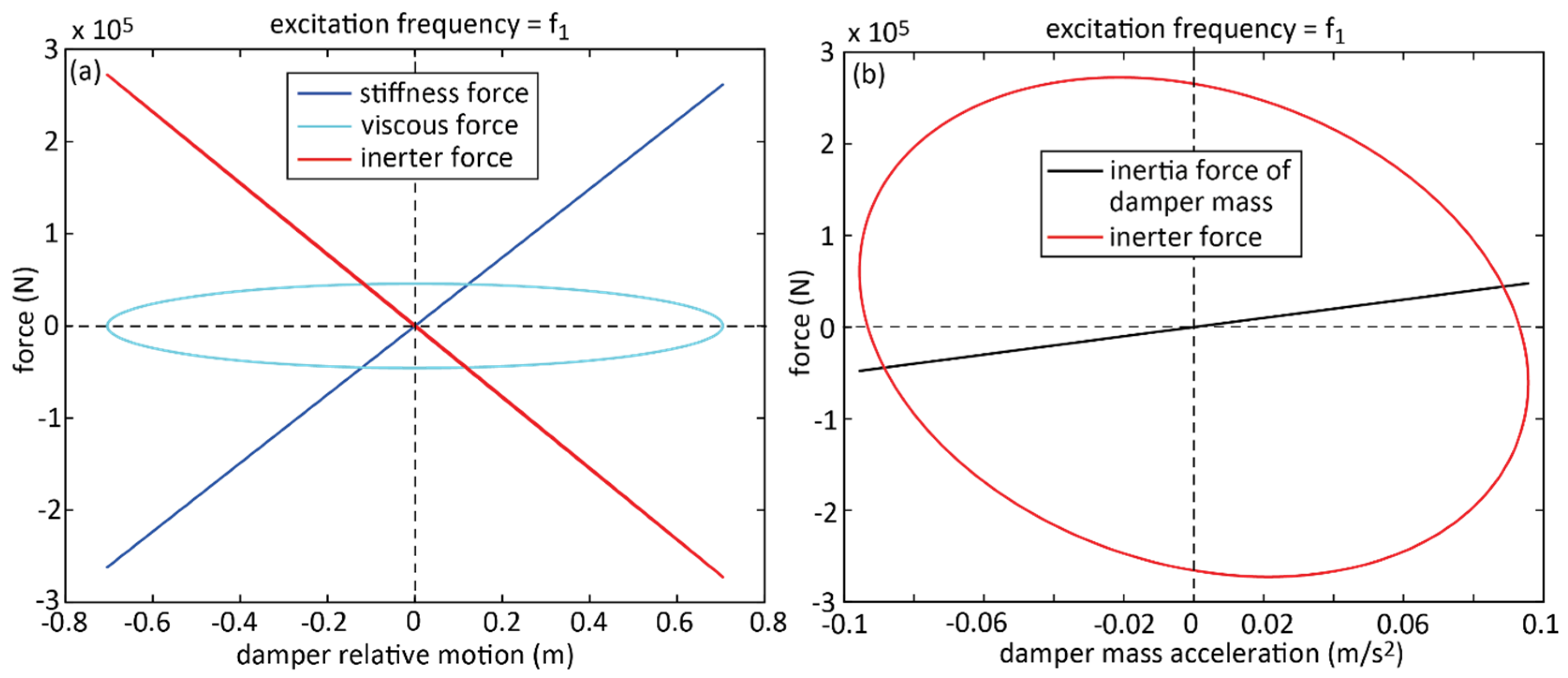
3.2. Inerter Force Characteristics

The coupling forces of the TMDI are its stiffness force, viscous damping force and inerter force. These forces are plotted in Figure 4a versus the damper relative motion x T M D x 10 . As expected, the stiffness force is in proportion to the damper relative motion, while the viscous force shows the typical ellipse in the force–displacement diagram. The inerter force, which is per definition in proportion to the difference between the accelerations of the top structural mass and the damper mass (see Equation (1)), shows a straight line with negative slope because of the phase shift of 180 ° between damper relative motion and damper relative acceleration. It can therefore be concluded that the presence of the inerter force influences the frequency tuning of the TMDI because the frequency tuning is determined by the positive slope of the stiffness force and the negative slope of the inerter force (Table 2).
Figure 4b plots the inertia force of the damper mass and the inerter force versus the (absolute) acceleration of the damper mass. It is clear from Newton’s second law that the inertia force of the damper mass is in direct proportion to the (absolute) acceleration of the damper mass. This is seen from the constant slope of the inertia force of the damper mass in black. In contrast, the inerter force is not a straight line because the inerter force is not in proportion to the (absolute) acceleration x ¨ T M D of the damper mass but in proportion to the difference between the structural acceleration and damper mass acceleration, i.e., x ¨ 10 x ¨ T M D . It is therefore evident that the inerter force is not an inertia force (Table 2). The elliptic shape of the inerter force is obtained when it is plotted versus the (absolute) damper mass acceleration. For harmonic excitation, this elliptic shape is also visible when the inerter force is plotted versus the absolute displacement of the damper mass. Considering the absolute displacement of the structural mass next to the TMDI, it can be concluded that the inerter force acts on the damper mass similar to an additional damping force. Hence, the presence of the inerter leads to an overdamped TMD. This is seen from the primary structure displacement response of the TMDI with Den Hartog tuning in Figure 1.

3.3. Approximate TMDI Tuning 1 (“Approximate Tuning 1”)

The first approximate tuning rule assumes that the mass ratio, being relevant for the design of the TMD natural frequency f T M D and TMD damping ratio ζ T M D , is determined by the sum of the TMD mass ratio μ and the inertance ratio β ; thus,
μ d e s i g n = μ + β
f T M D = f 1 1 + μ d e s i g n
ζ T M D = 3   μ d e s i g n 8   1 + μ d e s i g n 3
Since the inerter force is in proportion to TMD relative motion (Figure 4a), the inertance b is considered as mass in the design of the TMD stiffness:
k T M D = m T M D + b 2   π   f T M D 2
In contrast, the inertance b is not considered in the design of the TMD viscous coefficient c T M D as the inerter force is not in proportion to the damper relative velocity (see Figure 4a):
c T M D = 2   ζ T M D   m T M D   2   π   f 1
The primary structure response resulting from the “approximate tuning 1” (Equations (13)–(17)) is depicted in Figure 2 by the red curve. The higher right bump of the curve clearly shows that the natural frequency (Equation (14)) of “approximate tuning 1” is too low, while the shape of the curve indicates that the viscous damping is close to its optimum.

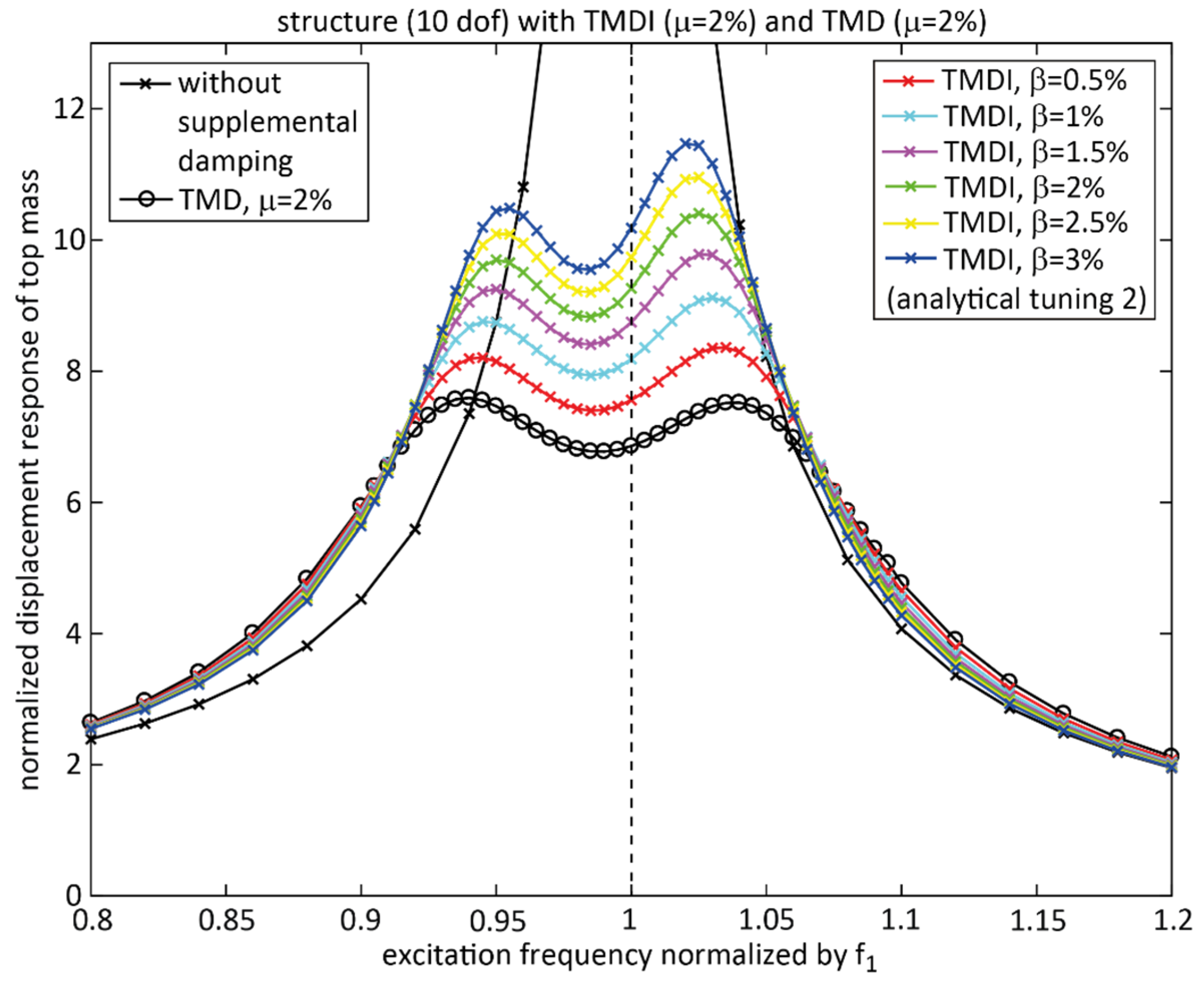
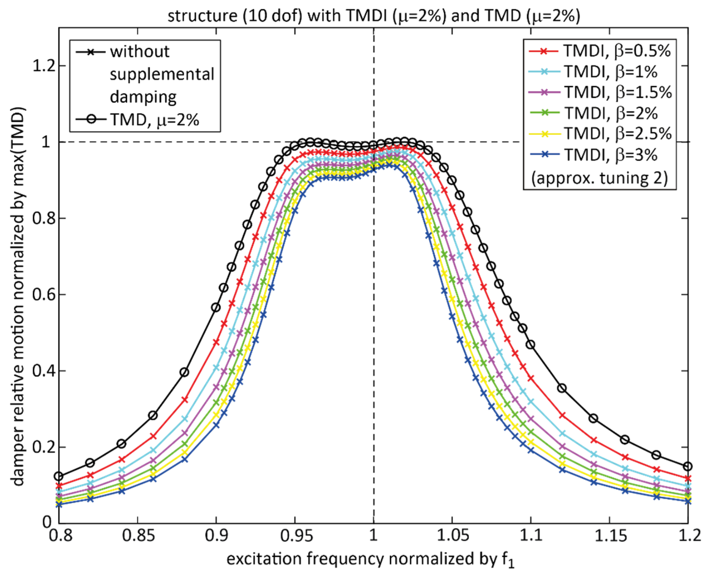
3.4. Approximate TMDI Tuning 2 (“Approximate Tuning 2”)

The second approximate tuning rule aims at tuning the damper stiffness somewhat higher to reduce the right bump of the red curve due to “approximate tuning 1”. The design mass ratio μ d e s i g n and the natural frequency f T M D are derived according to “approximate tuning 1” (Equations (13) and (14)). The TMD stiffness is slightly increased as follows:
k T M D = m T M D 2   π   f T M D 2 + b 2   π   f 1 2
because f 1 > f T M D . The TMD damping ratio ζ T M D and the TMD viscous damping coefficient c T M D are selected according to “approximate tuning 1” (Equations (15) and (17)). The resulting performance is depicted in Figure 2 by the green curve, which is almost congruent with the magenta curve. It is seen that “approximate tuning 2” generates two almost equal bumps meaning that “approximate tuning 2” almost represents the optimum tuning rule for a primary structure with the inherent damping ratio ζ 1 of 1%.

3.5. Approximate TMDI Tuning 3 (“Approximate Tuning 3”)

The third approximate tuning rule also envisages slightly increasing the damper stiffness to reduce the right bump of the red curve resulting from “approximate tuning 1”. This is achieved by designing the TMD natural frequency based on the TMD mass ratio only:
f T M D = f 1 1 + μ
to obtain a slightly higher f T M D . The TMD stiffness k T M D , the TMD damping ratio ζ T M D and the TMD viscous coefficient c T M D are selected according to “approximate tuning 1” (Equations (15)–(17)). Figure 2 shows that the resulting structural response is almost the same as for “approximate tuning 2”. The detailed analysis of the simulation data shows that “approximate tuning 2” performs slightly better than “approximate tuning 3”.

3.6. Approximate TMDI Tuning 4 (“Approximate Tuning 4”)

The left bumps resulting from “approximate tuning 2” and “approximate tuning 3” are still slightly lower than their right bumps. So, the fourth approximate tuning rule aims at further increasing the TMD stiffness. This is achieved by the TMD natural frequency according to “approximate tuning 3” (Equation (19)) and designing the TMD stiffness according to “approximate tuning 2” (Equation (18)). The TMD damping ratio ζ T M D and the TMD viscous coefficient c T M D are again selected according to “approximate tuning 1”. The resulting structural response, which is the blue curve in Figure 2, clearly shows that the TMD stiffness is now too high because the right bump is now significantly lower than the left.

4. Performance for Various Inertance Ratios

4.1. Considered Tuning, Mass Ratio and Inertance Ratios

The best performing approximate tuning rule for the TMDI assuming the typical mass ratio μ = 2% and for the inertance ratio β = 2% turned out to be “approximate tuning 2”. This tuning rule is applied to simulate the performance of the TMDI for the typical mass ratio μ = 2% and for the reasonable inertance ratios β = 0.5%, 1.0%, 1.5%, 2.0%, 2.5%, and 3.0%.

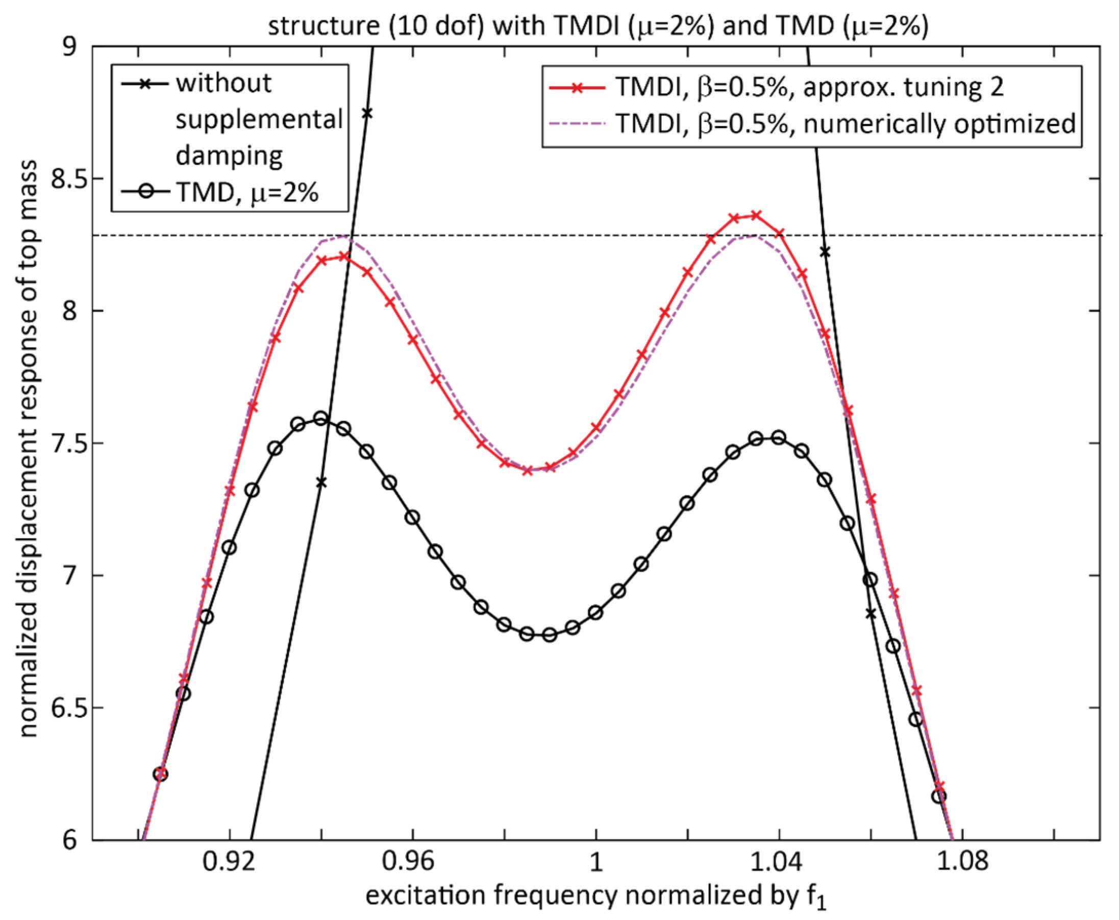
4.2. Double-Check of Approximate Tuning with Numerical Optimization

The tuning denoted “approximate tuning 2” is double-checked by numerical optimization of TMD stiffness k T M D and TMD viscous coefficient c T M D for μ = 2% and β = 2%. The associated normalized structural responses are depicted in Figure 5. The two bumps of the numerically optimized solution are equal and minimized demonstrating its optimality. The natural frequency of the numerical solution is only 0.21% higher than the natural frequency of “approximate tuning 2”, and the viscous damping coefficient of the optimal numerical solution is equal to the viscous damping coefficient according to “approximate tuning 2”. This means that the “approximate tuning 2” almost yields optimum parameters. It is therefore valid to simulate the performance of the TMDI for various inertance ratios with parameters according to “approximate tuning 2”.

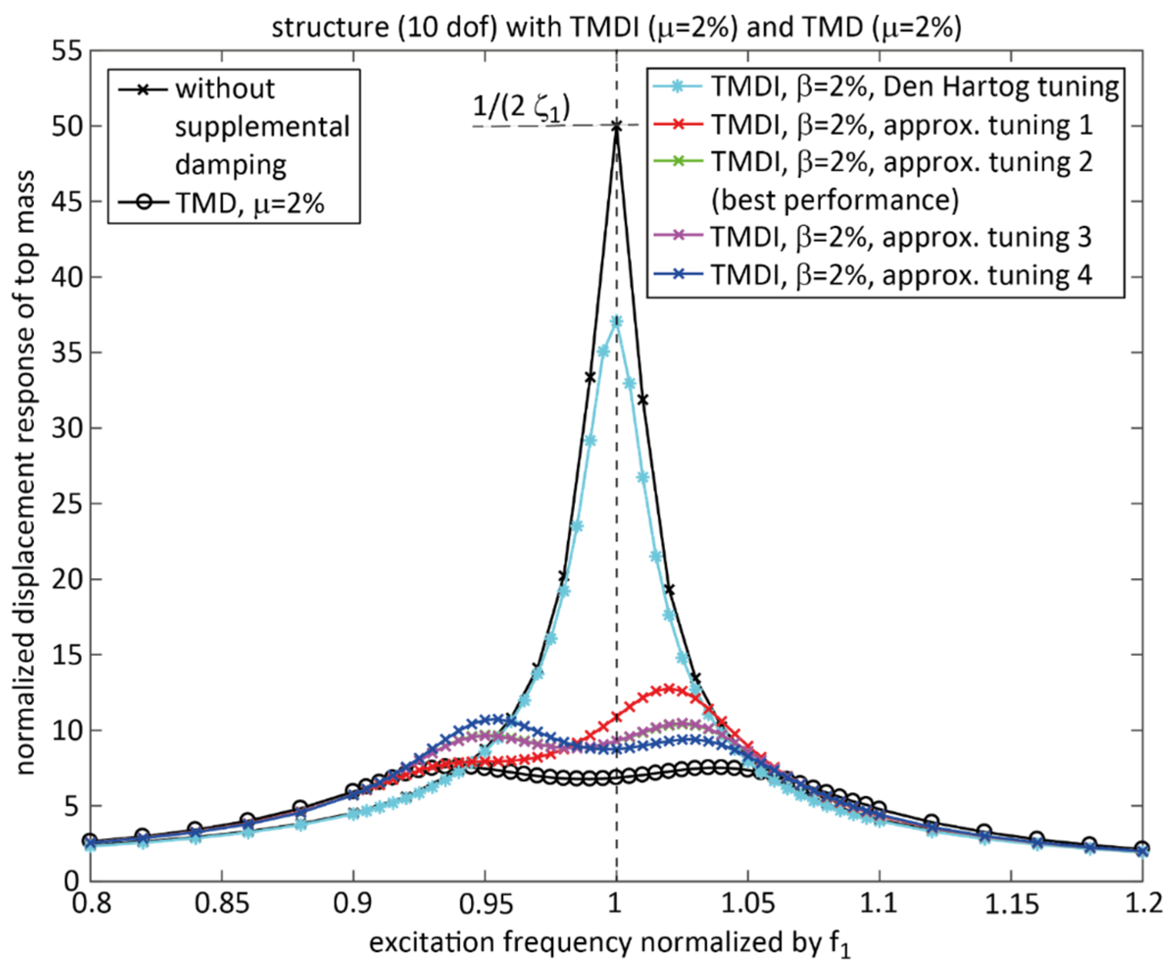
4.3. Performance Discussion

The performances in terms of normalized structural response and normalized damper relative motion resulting from “approximate tuning 2” and simulated for reasonable values of inertance ratios are depicted in Figure 6 and Figure 7. The results demonstrate that the TMDI with various inertance ratios performs worse than for the classical TMD. The structural response due to the TMDI becomes worse with increasing inertance ratio. The damper relative motion shows that the inerter reduces the relative motion (Figure 7). This also occurs when a classical TMD is overdamped, i.e., the TMD damping is selected greater than optimal, to reduce the TMD relative motion but with the drawback that the structural displacement response is then increased. This means that the inerter force rather acts as an additional damping force on the damper mass than an additional inertial force. This hypothesis is strengthened by the inerter force characteristics depicted in Figure 4b. The inerter force is not in proportion to the (absolute) acceleration of the damper mass but shows almost an elliptic behaviour.Figure 4a shows clearly that the inerter force acts as a negative stiffness force on the TMD mass. The presented approximate tuning rules of the stiffness coefficient of the TMD with inerter compensate for this negative stiffness force by the consideration of both the TMD physical mass and the inertance b in the derivation of the TMDI stiffness. As the tuning rule of the stiffness of the TMD with inerter compensates for the inerter negative stiffness force the derivation of the viscous coefficient of the TMD with inerter does not depend on the inertance b .

5. Conclusions

This article describes the performance of the TMDI for tall building damping. The most realistic TMDI configuration is considered where the inerter is connected to the TMD mass and the structural mass next to the TMD. This is the situation when the inerter, e.g., designed as a fly wheel mechanism, is connected to the pendulum mass of the TMD and grounded to the floor of the TMD room. Any friction or other non-ideal iinerter behaviour are not considered to assess the ideal TMDI. Also, TMDI configurations where the inerter is connected in series and parallel to additional dash pot dampers and springs are not considered as such TMDI configurations can hardly be realized.
For the considered realistic TMDI configuration, an approximate analytical tuning for the TMDI parameters is derived based on the characteristics of the inerter force. The comparison with the numerically optimized TMDI parameters shows that the derived approximate tuning solution only includes 0.21% error in its frequency tuning and zero error in its damping tuning.
The computations with this approximate but close-to-optimal tuning demonstrate that the classical TMD outperforms the TMDI for any inertance ratio. The physical reason for this result is that the inerter force is not an inertia force and hence does not increase the pendulum mass. This explanation directly results from the definition of the inerter force itself. The inerter force is in proportion to the relative acceleration of the two inerter terminals whereby it is not an inertial force, while the force of the damper mass is in proportion to the absolute acceleration of the damper mass according to Newton’s second law. The inerter force characteristics depicted in Figure 4a show that the inerter producesas a negative stiffness force for the case of harmonic excitation. This observation agrees with the fact that thestiffness of the TMD with inerter must be tuned considering both the TMD physical mass and the inertance to compensate for the negative stiffness force of the inerter.
There are many publications which suggest that the TMDI can improve the vibration mitigation compared to the classical TMD, especially for tall buildings where the pendulum mass may become considerably big because of the very big modal mass of the tall building. However, most of these publications come to this wrong conclusion because the simulations are performed for the unrealistic case that the inerter is grounded to earth or to a story significantly below the top story, i.e., a story at 50% of the building height or below. For the case that the inerter is grounded to earth, it is clear that the inerter force is then in proportion to the absolute acceleration of the pendulum mass only because the ground acceleration for the non-seismic scenario is zero. Then, the inerter force indeed leads to a “virtual” increase in the pendulum mass. However, to connect the inerter to ground or to a story at 50% of the building height or below is not realistic as it is not feasible to connect one inerter terminal to the pendulum mass, which is located close to or on top of the tall building, and one inerter terminal to a story far away from the top or even to earth.

Funding

This research received no external funding.

Data Availability Statement

All simulation data are available on request.

Acknowledgments

The author gratefully acknowledges the support of Maurer SE, Munich, Germany, Maurer Engineering GmbH, Munich, Germany, and Maurer Switzerland GmbH, Pfaffhausen, Switzerland.

Conflicts of Interest

Author Felix Weber was employed by the Maurer Switzerland GmbH. The author declares that the research was conducted in the absence of any commercial or financial relationships that could be construed as a potential conflict of interest.

References

  1. Den Hartog, J.P. Mechanical Vibrations, 4th ed.; McGraw-Hill: New York, NY, USA, 1956. [Google Scholar]
  2. Zucca, M.; Longarini, N.; Simoncelli, M.; Aly, A.M. Tuned Mass Damper Design for Slender Masonry Structures: A Framework for Linear and Nonlinear Analysis. Appl. Sci. 2021, 11, 3425. [Google Scholar] [CrossRef]
  3. Asami, T.; Nishihara, O.; Baz, A.M. Analytical solutions to H and H2 optimization of dynamic vibration absorber attached to damped linear systems. J. Vib. Acoust. ASME 2002, 124, 284–295. [Google Scholar] [CrossRef]
  4. Kim, S.M.; Wang, S.; Brennan, M.J. Optimal and robust modal control of a flexible structure using an active dynamic vibration absorber. Smart Mater. Struct. 2011, 20, 045003. [Google Scholar] [CrossRef]
  5. Weber, F.; Yalniz, F.; Kerner, D.; Huber, P. Performance of Adaptive TMD for Tall Building Damping. Int. J. High-Rise Build. 2021, 10, 99–107. [Google Scholar] [CrossRef]
  6. Giaralis, A.; Petrini, F. Wind-induced vibration mitigation in tall buildings using the tuned mass-damper-inerter (TMDI). J. Struct. Eng. 2017, 143, 04017127. [Google Scholar] [CrossRef]
  7. Pietrosanti, D.; De Angelis, M.; Basili, M. Optimal design and performance evaluation of systems with Tuned Mass Damper Inerter (TMDI). Earthq. Eng. Struct. Dyn. 2017, 46, 1367–1388. [Google Scholar] [CrossRef]
  8. Dai, J.; Xu, Z.D.; Gai, P.P. Tuned mass-damper-inerter control of wind-induced vibration of flexible structures based on inerter location. Eng. Struct. 2019, 199, 109585. [Google Scholar] [CrossRef]
  9. Petrini, F.; Giaralis, A.; Wang, Z. Optimal tuned mass-damper-inerter (TMDI) design in wind-excited tall buildings for occupants’ comfort serviceability performance and energy harvesting. Eng. Struct. 2020, 204, 109904. [Google Scholar] [CrossRef]
  10. Wang, Q.; Qiao, H.; Li, W.; You, Y.; Fan, Z.; Tiwari, N. Parametric optimization of an inerter-based vibration absorber for wind induced vibration mitigation of a tall building. Wind Struct. 2020, 31, 241–253. [Google Scholar]
  11. Weber, F.; Huber, P.; Borchsenius, F.; Braun, C. Performance of TMDI for Tall Building Damping. Actuators 2020, 9, 139. [Google Scholar] [CrossRef]
  12. Barredo, E.; Larios, M.; Mayén, J.; Flores-Hernández, A.A.; Colín, J.; Arias-Montiel, M. Optimal design for high-performance passive dynamic vibration absorbers under random excitation. Eng. Struct. 2019, 195, 469–489. [Google Scholar] [CrossRef]
  13. Barredo, E.; Larios, M.; Colín, J.; Mayén, J.; Flores-Hernández, A.A.; Arias-Montiel, M. A novel high-performance passive non-traditional inerter-based dynamic vibration absorber. J. Sound Vib. 2020, 485, 115583. [Google Scholar] [CrossRef]
  14. Alotta, G.; Failla, G. Improved inerter-based vibration absorbers. Int. J. Mech. Sci. 2021, 192, 106087. [Google Scholar] [CrossRef]
  15. Weber, F.; Borchsenius, F.; Distl, J.; Braun, C. Performance of numerically optimized Tuned Mass Damper with Inerter (TMDI). Appl. Sci. 2022, 12, 6204. [Google Scholar] [CrossRef]
  16. Smith, M.C. The Inerter: A Retrospective. Annu. Rev. Control. Robot. Auton. Syst. 2020, 3, 361–391. [Google Scholar] [CrossRef]
Figure 1. (a) Considered realistic TMDI configuration for tall building damping; (b) considered benchmark system.
Buildings 15 01829 g001
Figure 2. Normalized primary structure displacement with TMDI with considered tunings and TMD with same mass ratio.
Buildings 15 01829 g002
Figure 3. Normalized damper relative motion of TMDI with considered tunings and TMD with same mass ratio.
Buildings 15 01829 g003
Figure 4. (a) Coupling forces of TMDI versus damper relative motion; (b) inertia force of damper mass and inerter force versus damper mass (absolute) acceleration.
Buildings 15 01829 g004
Figure 5. Normalized primary structure displacement with TMDI with “approximate tuning 2”, TMDI with numerically optimized parameters and TMD with same mass ratio.
Buildings 15 01829 g005
Figure 6. Normalized primary structure displacement with TMDI with various inertance ratios and TMD with same mass ratio.
Buildings 15 01829 g006
Figure 7. Normalized damper relative motion of TMDI with various inertance ratios and TMD with same mass ratio.
Buildings 15 01829 g007
Table 1. Structural modal parameters and TMDI/TMD main parameters.
Modal Mass of First Bending Mode (t)Eigenfrequency of First Bending Mode (Hz)Damping Ratio of First Bending Mode (%)Considered Inertance Ratios (%)Mass Ratio (%)Pendulum Mass (t)
25,000 t0.14 Hz1%0.5%, 1%, 1.5%, 2%, 2.5%, 3%2%500 t
Table 2. Influence of inerter force characteristics on damper behaviour.
Influence on Frequency Tuning of DamperInfluence on Inertia of Damper
The presence of the inerter force influences the frequency tuning of the TMDI because the frequency tuning is determined by the positive slope of the stiffness force and the negative slope of the inerter force.The inerter force is not an inertia force but it acts rather as an additional damping force on the oscillating damper mass.
Disclaimer/Publisher’s Note: The statements, opinions and data contained in all publications are solely those of the individual author(s) and contributor(s) and not of MDPI and/or the editor(s). MDPI and/or the editor(s) disclaim responsibility for any injury to people or property resulting from any ideas, methods, instructions or products referred to in the content.

