Article

Experimental and Theoretical Investigation on Cracking Behavior and Influencing Factors of Steel-Reinforced Concrete Deep Beams

1
College of Civil Engineering and Architecture, Anhui Polytechnic University, Wuhu 241000, China
2
Engineering Research Center of Anhui Green Building and Digital Construction, Anhui Polytechnic University, Wuhu 241000, China
3
School of Civil Engineering and Transportation, Guangzhou University, Guangzhou 510006, China
4
Research Centre for Wind Engineering and Engineering Vibration, Guangzhou University, Guangzhou 510006, China
*
Author to whom correspondence should be addressed.
Buildings 2025, 15(11), 1812; https://doi.org/10.3390/buildings15111812
Submission received: 1 May 2025 / Revised: 15 May 2025 / Accepted: 22 May 2025 / Published: 25 May 2025
(This article belongs to the Special Issue Advances in Building Structure Analysis and Health Monitoring)

Abstract

:
Steel-reinforced concrete (SRC) deep beams have been widely used in engineering applications such as high-rise buildings and long-span bridges, with their structural behavior and mechanical properties attracting significant research attention. To investigate the shear cracking behavior of SRC deep beams, seven specimens with a scale of 0.4 times were designed for static loading tests, and the influence of the shear-span-to-depth ratio λ, the width ratio of the steel flange, and the height ratio of the steel web on the width and spacing of the diagonal crack was considered. The cracking behavior of the diagonal cracks in the shear span area were recorded by the digital image correlation (DIC) technique. The results show the following: (1) the use of the DIC technology revealed the entire process of crack occurrence, development, and evolution and obtained the distribution characteristics of crack development; (2) the steel flange width has a slight effect on the spacing and width of the diagonal cracks. The diagonal crack width increased with the improvement of the height of the steel web, but the influence of the steel web on the spacing of diagonal cracks was not significant. When the height ratio increased from 0.3 to 0.45 and 0.6, the maximum oblique crack width increased by 13% and 14.5%. Based on the above experimental results and relevant analysis conclusions, an improved method was proposed to calculate the diagonal crack width of composite deep beams by further considering the influence of the crack angle. Finally, the experimental results verified its high accuracy in a qualitative analysis. The calculation method proposed in this article can be used to predict and estimate the width of diagonal cracks in SRC deep beams.

1. Introduction

Steel-reinforced concrete (SRC) deep beams are composite structural members consisting of a steel skeleton, reinforcing bars, and concrete, which synergistically combine the high tensile strength of steel with the compressive strength of concrete. Owing to their exceptional load-bearing capacity, stiffness, and seismic resistance, SRC deep beams are extensively employed in critical infrastructure such as high-rise buildings, offshore platforms, long-span bridges, and industrial storage tanks [1,2,3,4,5,6]. Unlike conventional slender beams, SRC deep beams exhibit unique mechanical behavior due to their low shear–span ratio (typically less than 2.5), leading to distinct shear-dominated failure mechanisms and complex stress redistribution [7,8,9].
Crack development is a vital indicator of structural integrity and serviceability in concrete members. In SRC deep beams, crack characteristics—including width, propagation pattern, and distribution—are critical for assessing damage levels and ensuring compliance with design codes. Experimental and numerical studies [10,11,12] have demonstrated that under shear loading, SRC deep beams typically fail through diagonal cracking (Figure 1), a brittle failure mode initiated when principal tensile stresses exceed the concrete’s tensile capacity. Once diagonal cracks form, they propagate rapidly, causing a significant reduction in stiffness and load-carrying capacity, ultimately leading to abrupt collapse without sufficient warning [13,14]. This brittle behavior underscores the importance of robust shear reinforcement design and crack control strategies in SRC deep beam applications.
At present, extensive research has been conducted to investigate the cracking behavior of both SRC deep beams and slender beams [15,16]. Numerous experimental and analytical studies have examined key parameters affecting shear crack development, including the shear-span-to-depth ratio, concrete compressive strength, cross-sectional dimensions, and the stirrup reinforcement ratio [17,18]. These studies consistently demonstrate that the maximum crack width exhibits an inverse relationship with both concrete compressive strength and member size. Furthermore, research has established important relationships between diagonal crack propagation and ultimate load capacity [19] and has also investigated crack width–spacing correlations in glass-FRP reinforced members [20]. A critical finding indicates that diagonal cracking significantly reduces the residual load-bearing capacity of reinforced concrete deep beams, highlighting the detrimental effect of shear cracks on structural performance.
The composite interaction between steel skeletons and surrounding concrete in SRC deep beams has been experimentally verified [11], confirming that the steel skeleton’s contribution to structural behavior cannot be overlooked. To account for this composite action, researchers have developed analytical models such as the softened strut-and-tie (SST) model [21] and its SRC-adapted variant (SST-SRC model) [10], both of which effectively predict shear strength while demonstrating the steel skeleton’s crucial role in shear resistance mechanisms. Furthermore, the EB-FIP model [22] specification proposes a systematic theoretical framework and calculation method for concrete cracking verification. By introducing correction factors that consider special working conditions such as loading speed and environmental temperature, it has been applied in multiple engineering structural fields. However, some of its theoretical assumptions are overly simplified (such as not fully reflecting the nonlinear creep characteristics of concrete) and have a strong dependence on empirical parameters (such as the crack width formula needing to be combined with regional correction factors).
Despite these advances, the current research exhibits two significant gaps: (1) limited investigations into how steel skeletons influence diagonal crack formation and propagation in SRC deep beams and (2) the absence of comprehensive theoretical models for predicting crack widths in such members. Addressing these knowledge gaps is essential for developing accurate performance assessment methods and ensuring the long-term durability of SRC deep beam structures. A thorough understanding of cracking characteristics and the development of reliable crack width prediction models would significantly improve the serviceability limit state design and remaining life estimation for these critical structural elements.
Regarding crack width measurement, conventional experimental approaches typically employ optical magnifiers, displacement transducers, or microscopes. While these methods provide localized measurements, they suffer from significant limitations: (1) they can only capture discrete data points at instrument attachment locations, (2) they offer limited spatial resolution of crack propagation patterns, and (3) they are incapable of comprehensive, real-time monitoring of crack initiation and development across the entire structural surface. To overcome these limitations, this study introduces digital image correlation (DIC) as an advanced, non-contact optical measurement technique. As demonstrated in previous studies [23,24], DIC enables full-field displacement and strain measurement by analyzing digital image sequences captured during loading. This innovative approach provides three key advantages over traditional methods: (1) it captures the complete crack formation process across the entire specimen surface; (2) it allows the precise tracking of initial crack location and subsequent propagation; (3) it eliminates the need for complex instrumentation while maintaining measurement accuracy [25].
In the present experimental investigation, the DIC technique was systematically employed to (1) quantify the shear deformation characteristics of SRC deep beam specimens; (2) monitor the complete evolution process of diagonal cracks in shear-critical regions (from initiation to final failure mode); and (3) validate the spatial distribution of crack patterns. The results demonstrate the superior capability of this non-contact optical method in characterizing deformation behavior and crack development in concrete structures, particularly for capturing the complex shear cracking phenomena in SRC deep beams that conventional methods often miss.
This paper experimentally investigates the shear cracking behavior of seven SRC deep beams, examining the effects of the shear-span-to-depth ratio (λ), steel flange width ratio, and steel web height ratio on diagonal crack development. Using digital image correlation (DIC) technology, we precisely captured the cracking loads and monitored the complete evolution process of diagonal cracks in shear span regions. Based on the bond–slip theory, we propose and experimentally validate a new analytical formula for calculating diagonal crack widths in SRC deep beams. This study provides both experimental evidence and theoretical support for understanding shear behavior and crack development mechanisms in SRC deep beams, offering valuable insights for their design and performance assessment.

2. Experimental Setup

2.1. Specimen Details

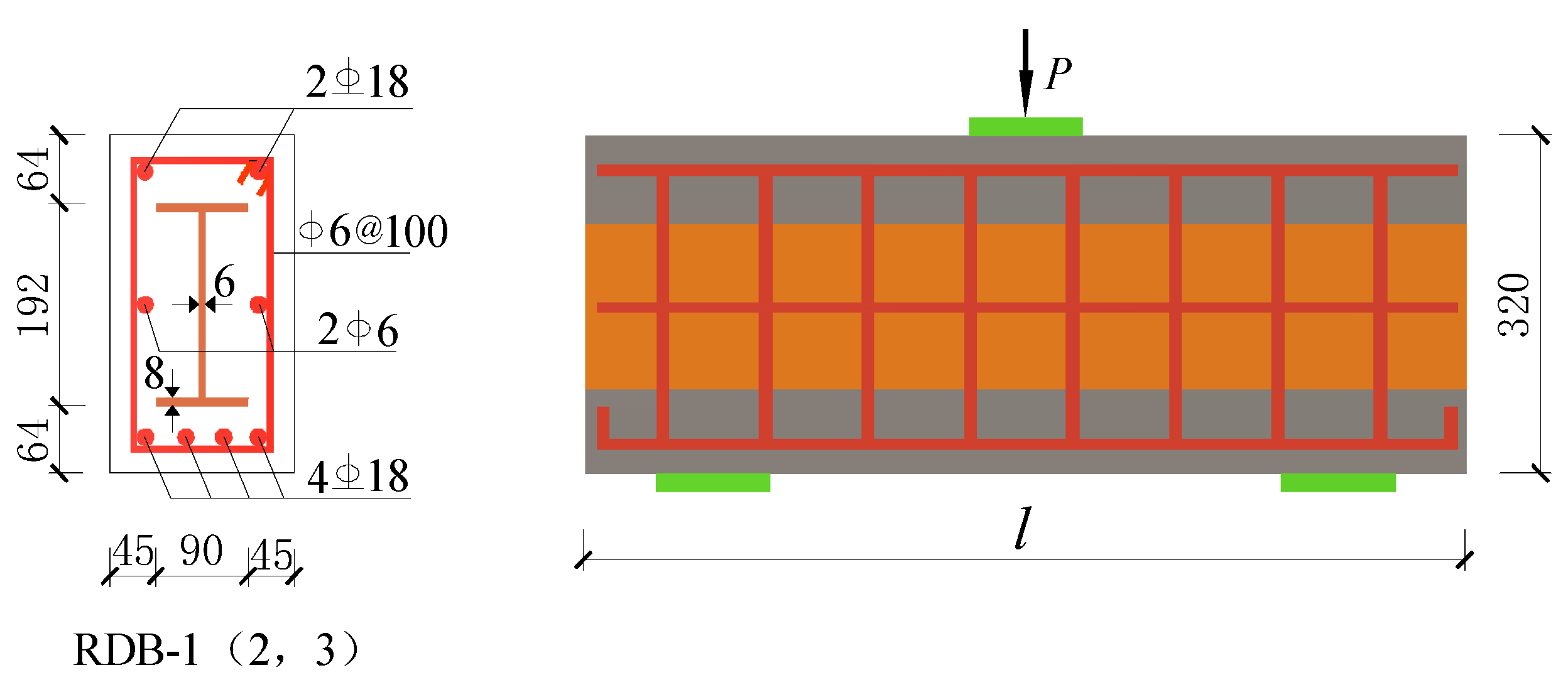
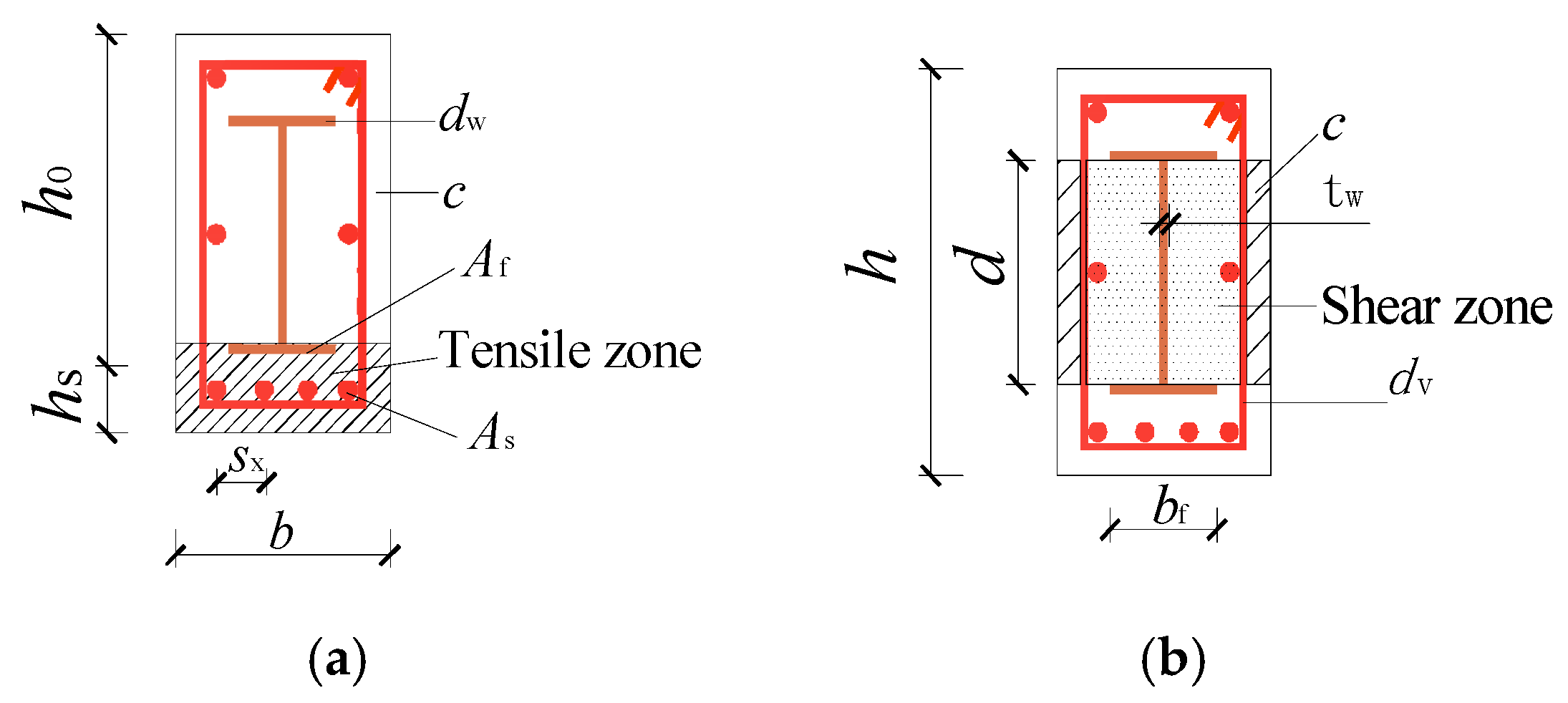
In this study, seven SRC deep beam specimens with a scale of 0.4 times were designed for static loading tests. The cross-sectional dimensions of all specimens were 180 × 320 mm and the length ranged from 860 mm to 1200 mm. The specimens were labelled from RDB-1 to RDB-7. The section size and layout of reinforcement bars are shown in Figure 2. Four longitudinal bars 18 mm in diameter were situated at the bottom of the beam, while two longitudinal bars were situated at the top of the beams. The stirrups were 6 mm in diameter with 100 mm spacing. Table 1 lists the details of the main variables, including the height ratio, width ratio, and shear-span-to-depth ratio ( λ ). The height ratio is the ratio of steel section height to beam section height. The width ratio is the ratio of the steel flange width to the beam section width.

2.2. Material Properties

Testing of the specimen materials was conducted according to the requirements given in the Chinese code [26,27]. The average cube of the concrete had a side length of 150 mm. The compressive strength fcu of ordinary commercial C40 concrete is 41 MPa, and its Young’s modulus is 3.31 × 10⁴ MPa. HRB335 bars were adopted for longitudinal reinforcement and HPB300 bars for stirrups. H-shaped steel was welded by Q235 steel. All steel materials were subjected to tensile tests. The measured values of steel properties are listed in Table 2.

2.3. Test Setup

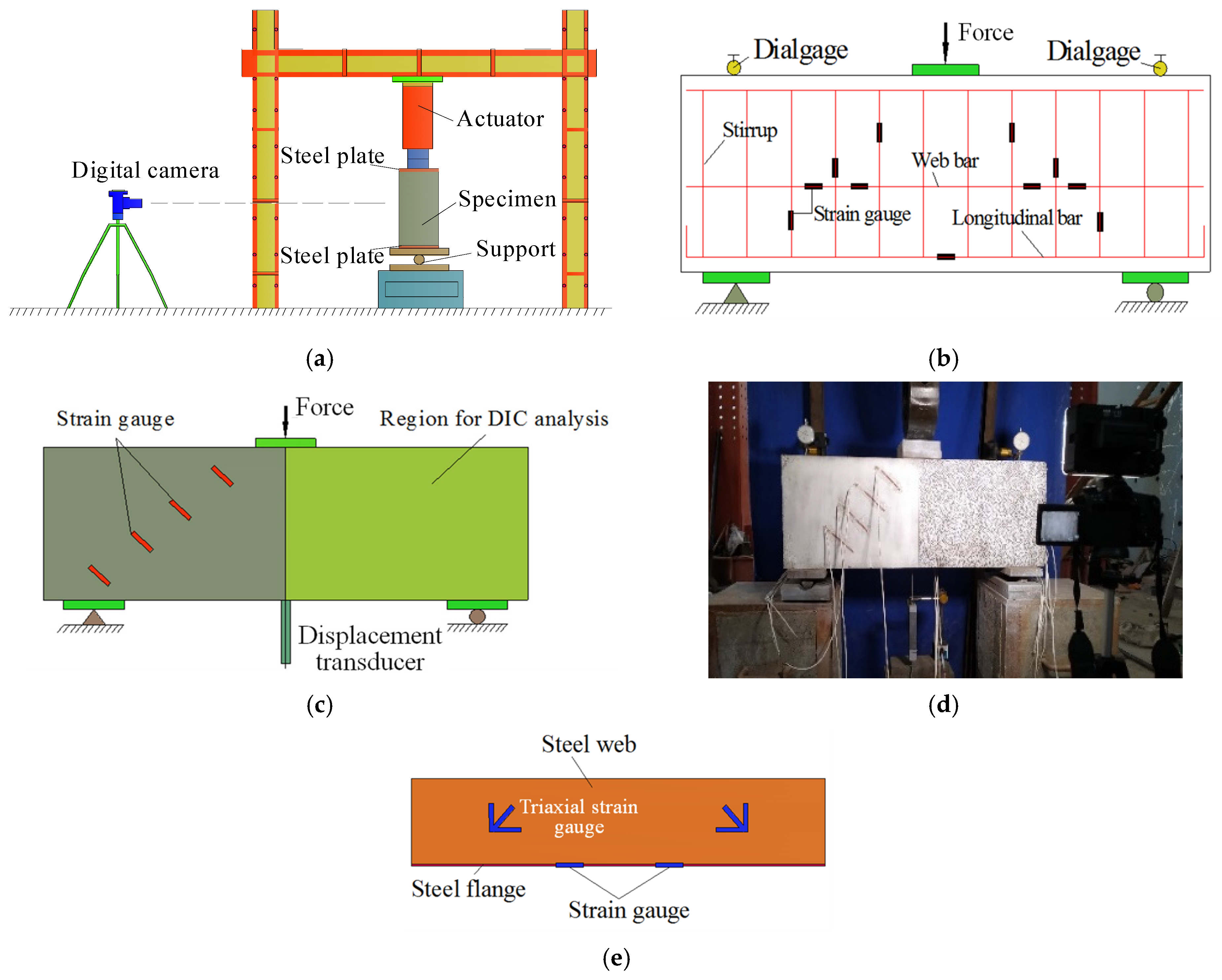
The SRC deep beams were simply supported. Specimens were subjected to a three-point bending test, as shown in Figure 3a,c. The vertical displacement of the middle span was recorded by a displacement meter, and the strains of the concrete, rebar, and steel skeleton were measured by strain gauges (Figure 3b–e). The rigid plates had dimensions of 20 mm (thickness) × 100 mm (width) × 180 mm (length) and were placed between the specimen and support to prevent stress concentrations. A displacement-controlled method was adopted for monotonic loading with a rate of 0.5 mm/min. The experiment concluded once the bearing capacity dropped to 85% of the maximum load.

2.4. Digital Image Correlation Technique (DIC)

In addition to traditional strain gauges and displacements, the 2D-DIC technique is also adopted to monitor crack development and measure deformation on the beam surface. Two-dimensional DIC is a non-destructive, optical–numerical, and non-contacting full-field measurement technique that has proven effective in monitoring structural health and material deformation [28,29]. The principle of this technique is to estimate the full-field displacements and strains of the specimen’s surface by analyzing the random speckle pattern before and after specimen deformation. The measurement system consists of a computer, a high-definition digital camera, and a white-light source. The white-light source and camera were pointed directly at the shear failure area of the specimen. In this test, a digital camera shot an image of the specimen deformation at every 10 kN load increment. All the images were transmitted to a computer and recorded in synchrony with the applied forces and displacements during the experiment. Computational software was used to process the digital photos of the required displacements and strains.

3. Test Results

3.1. General Behavior and Failure Mode

Table 3 lists the peak loads and failure modes of all the specimens. The development of diagonal cracks in the shear zone was severe when the load reached the ultimate bearing capacity of the beam. The seven SRC deep beams shared similar shear cracking patterns. With the exception of RDB-6, which experienced bearing failure, all the specimens exhibited diagonal compression failure. Many diagonal cracks developed from the loading point to the support point. The bearing failure indicated that the steel skeleton of the RDB-6 beam provided a greater shearing force, which led to the crushing of the concrete at the bearing point before the specimen reached diagonal compression failure.
The crack propagation was recorded by DIC throughout the whole experiment. Figure 4 shows the developed crack patterns and the principal strain contours of the specimens observed by DIC.
The figure shows that flexural cracks primarily appeared in the middle span, but no further development occurred. Afterwards, the shear cracks developed gradually. The load at the first flexural crack of all specimens ranged from 60 kN to 110 kN. As the load increased, the elastic crack slowly developed upward, and several small vertical cracks were observed at the bottom of the mid-span. But the development of vertical cracks was not serious. When the load increased to 15~26% of the peak load, the vertical cracks gradually extended into diagonal cracks. After this event, diagonal cracks developed rapidly and became more severe with the increase in load. The crack development recorded by the DIC showed that the diagonal cracks first appeared in the lower web of the beam and then extended to the support. The final patterns of the diagonal cracks were wide in the middle and narrow at both ends. The loads at the first flexural crack and first shear crack are presented in Table 3.
The load–displacement curves of all the specimens are shown in Figure 5. The specimens are divided into three groups according to the shear-span-to-depth ratio ( λ ), width ratio, and height ratio. The results demonstrate that both the shear-span-to-depth ratio and steel dimensions significantly affect the bearing capacity of deep beams. When the ratio increases from 1.1 to 1.4 and 1.7, the ultimate bearing capacity decreases by 13.3% and 30.4%, respectively, and the attenuation rate shows a nonlinear acceleration trend. The displacement at the ultimate load also decreases correspondingly. The coefficient of variation of the initial cracking load is 25.6%, among which the discreteness of the shear initial cracking load (100–160 kN) is significantly greater than that of the bending initial cracking load (60–110 kN), which may be related to the sensitivity of local defects in the specimen. However, specimens with larger ratios exhibit slower post-peak displacement degradation.
Specimens RDB-2 and RDB-3 demonstrate superior ductile performance compared to other beams. Increasing either the steel web height ratio or flange width ratio enhances the specimen bearing capacity. When the height ratio increases from 0.3 to 0.45 and 0.6, the ultimate bearing capacity improves by 13.7% and 22%, respectively. Similarly, increasing the width ratio from 0.33 to 0.5 and 0.67 yields capacity enhancements of 12.8% and 17%. While higher width ratios lead to increased displacement at the ultimate load, they concurrently reduce post-yield ductility, potentially inducing brittle fracture modes.

3.2. Diagonal Crack Spacing

In this paper, the diagonal crack spacing in the shear span region is measured. The measured values are presented in Table 4. The average spacing is calculated by averaging all diagonal crack spacing. The distance is defined as the length of a straight line perpendicular to the midpoint of two cracks. The average diagonal crack spacing of all beams is between 35.8 mm and 56.4 mm. As shown in Figure 4, the larger the spacing, the greater the number of diagonal cracks in the shear area.
Furthermore, the spacing of diagonal cracks decreases as their number increases. When the number increased to 1.4 and 1.7 times the original value, the diagonal crack spacing reduced by 11.3 mm and 6.4 mm, respectively. The average crack spacing among three groups of specimens with width ratios ranging from 0.3 to 0.6 was between 35.8 mm and 56.4 mm. Simultaneously, the diagonal crack spacing showed an increasing trend with higher width ratios. When the width ratio increased from 0.33 to 0.5, the spacing increased by 20.6 mm. However, a further increase from 0.5 to 0.67 resulted in only a 0.6 mm spacing increment.
The experimental results demonstrate that crack spacing increases with bearing capacity improvement. The results indicate that crack spacing (46.9–56.4 mm) varies with height ratios (0.33–0.67). Increasing the steel web height enhanced the ultimate bearing capacity while simultaneously increasing diagonal crack spacing. The statistical data in Table 4 show that establishing a direct correlation between crack spacing and other parameters proves challenging based solely on spacing measurements. By combining digital image correlation (DIC) crack patterns with measured data, it becomes evident that diagonal crack spacing l m correlates with the angle of inclination θ (Figure 4).

3.3. Diagonal Crack Width

The crack width is the most important index predicting the service life of a specimen and can be used to evaluate its crack resistance. Therefore, more attention needs to be focused on understanding the factors affecting crack width. Experimental data suggest that the crack width undergoes three development stages: (1) the elastic stage, when the diagonal crack has not yet appeared, and the concrete is in the elastic regime; (2) the crack development stage, where the diagonal crack has developed to a severe extent and its width increases rapidly with the increase in load; (3) the stable stage, where the crack width develops slowly and plateaus until the ultimate load is reached. The relationship between diagonal crack width and loading is shown in Figure 6. The test results of the crack width as processed from the DIC images are listed in Table 5.
The average crack width in specimen RDB-1 is 0.9 mm, while that in specimens RDB-2 and RDB-3 is 0.76 mm and 0.68 mm, respectively. The diagonal crack width decreases with the increase of the λ . The size of the section steel web has a significant influence on the crack width. When the height ratio increased from 0.3 to 0.45 and then to 0.6, the average crack width increased by 0.32 mm and 0.63 mm, respectively. Although the flange of the steel skeleton has a significant influence on the ultimate bearing capacity, it has a slight influence on the diagonal crack width. The test results show that when the width ratio increased from 0.33 to 0.5 and then to 0.67, the average crack width increased by only 0.02 mm and 0.05 mm, respectively.
The possible reason for these test results is that the bearing capacity of specimens decreases with the increase in the λ. When the ultimate bearing capacity of the specimen is reached, the crack has not fully developed. Moreover, when the crack width is relatively large, more diagonal cracks are generated in the shear area due to the effects of shear stress and bending stress. Therefore, there are diagonal cracks with small spacing and widths in RDB-2 and RDB-3. In specimens RDB-1 and RDB-4~RDB-7, the size of the steel skeleton is increased, which leads to higher ultimate bearing capacities, but the effect of the steel skeleton on the diagonal crack is different from before. The results show that the average width of the diagonal crack increases with the steel web size, but the influence on the diagonal crack spacing is slight. Similarly, increasing the flange width has little effect on the diagonal crack spacing.

4. Derivation of Diagonal Crack Width Calculation Method

4.1. Diagonal Crack Width Formula

The maximum diagonal crack widths under the service state as well as at the beginning of shear capacity are important information in evaluating the shear performance of reinforced concrete members after cracking. The CEB-FIP Model Code [22] recommends that the maximum diagonal crack width is 1.7 times the average diagonal crack width. The maximum diagonal crack width can be expressed as
w k = 1.7 k w w m
where k w is the influence coefficient for the stirrup angle (1.2 and 0.8 for vertical stirrups and inclined stirrups, respectively).
The diagonal crack width is usually obtained by an experimental instrument or theoretical calculation method. The existing theoretical model is based on the assumption that the shear crack width is approximately linear with the stirrup strain. It follows that the average diagonal crack width w m is equal to the product of the average spacing of diagonal cracks l m and the stirrup strain ε w .
w m = l m ε w
s m = 2 c + s 10 + k 1 k 2 ϕ ρ r d - x sin a
where c is the concrete cover and s is the reinforcement bar spacing. For a plain round bar, k 1 is 0.8, and for ribbed steel bars, k 1 is 0.4; ϕ is the reinforcement bar diameter and ρ r is the steel ratio.
Many scholars also put forward the calculation formula of diagonal crack width. Hassan et al. [30] assumed that the average diagonal crack width is related to the stirrup diameter, strain, and reinforcement ratio. The average diagonal crack width w m can be expressed as
w m = ϕ 1000 S k 1 k 2 k fc k p
where ϕ is the stirrup diameter. For a plain round bar, the k 1 is 2.4, S = 4 × 10 3 ε w + 2 × 10 6 ε w 2 . For ribbed steel bars, k 1 is 2.0, S   = 8 × 10 3 ε w + 2 × 10 6 ε w 2 ; k 2 is 1.2; k p = ρ w 0.004 1.3 ; k fc = f c 19.6 2 3 ; and f c is the compressive strength of concrete.
However, according to the research of Fukuyama et al. [31], the average diagonal crack width w scr is also related to the overall depth of the section D , as follows:
w scr = 0 . 9 D ε s w 2
where D is the depth of the beam and ε s w is the stirrup strain.
Shinomiya et al. [32] and Piyamahant [33] gave the theoretical calculation formula obtained by their research. The average diagonal crack width w m can be expressed as
w av = l av ε t , av
where l av is the diagonal crack spacing, l av = 2 c s + c b 2 + s 10 + 0.1 ϕ ρ e , and ρ e = A w 2 C b + φ / b ; b is the beam width, c b = s y - φ / 2 , c is the concrete cover, s is the stirrup spacing, ε t , av is the stirrup strain, and s y is the stirrup leg width.
w av = 2 d v s f c / 20 2 / 3
s = ε w 6 + 3500 ε w
where f c is the compressive strength of concrete; d v is the reinforcement bars diameter; and ε w is the stirrup strain.
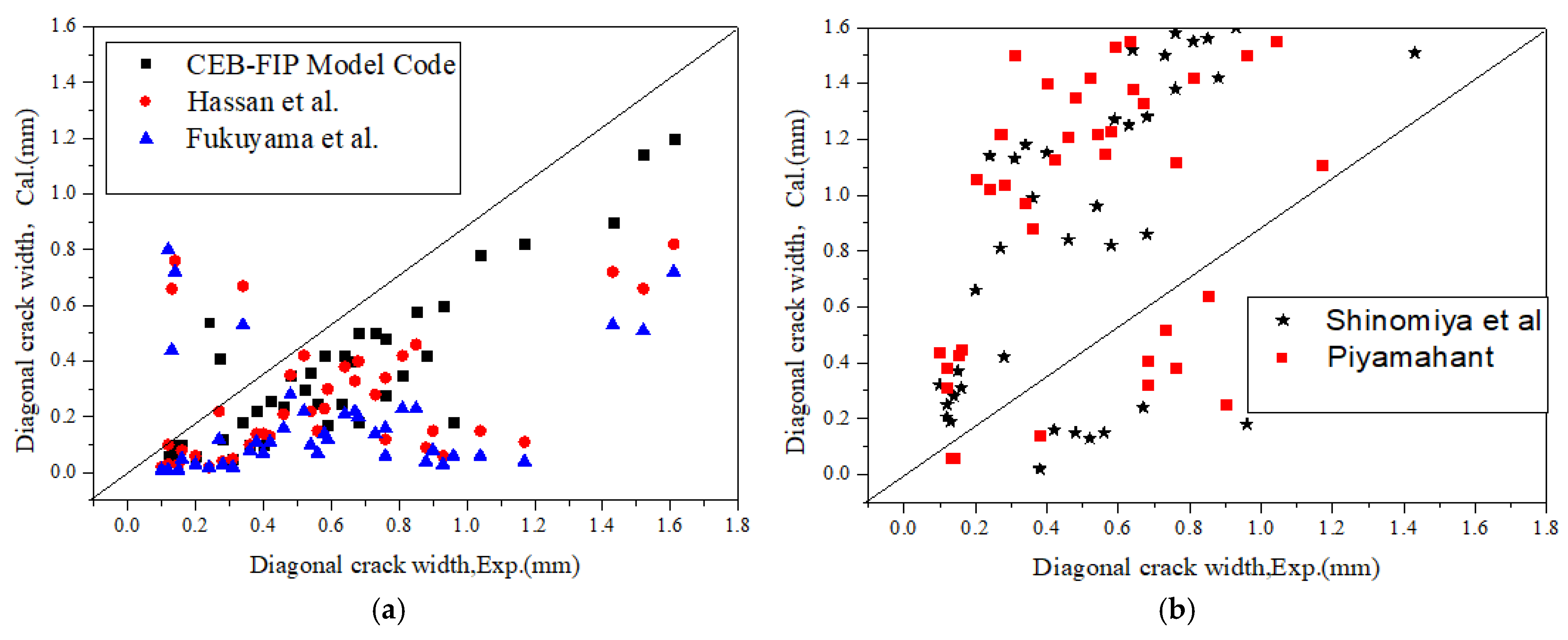
These theoretical models emphasize the important effects of stirrup strain and diagonal crack spacing on average crack width. In order to verify the applicability of the existing prediction formulas for the diagonal crack width of SRC deep beams, the diagonal crack width calculated by each prediction formula was compared with the measured value in the test, as shown in Figure 7a,b.
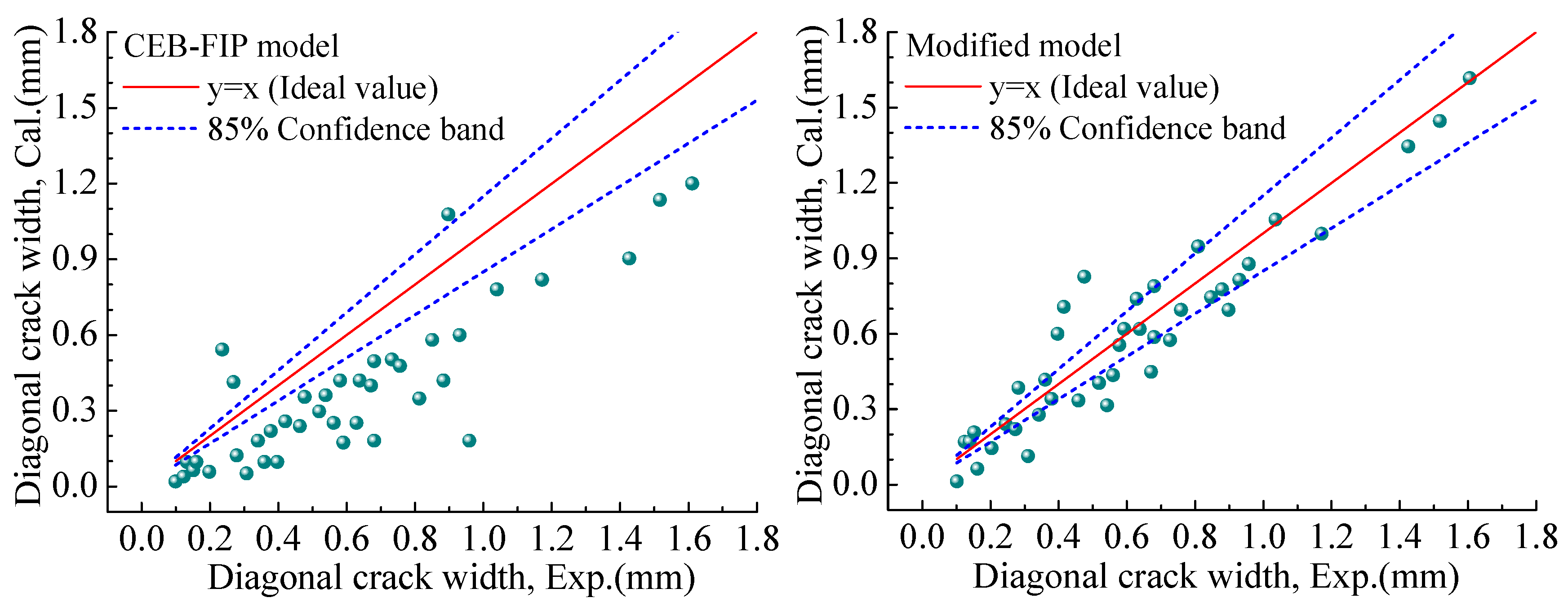
It can be clearly found that although the predicted diagonal crack width is the average width, the shear diagonal crack width calculated by all equations is highly discrete from the test results. This may be because the study parameters of the specimen and the existence of the built-in steel skeleton have an effect on the diagonal crack width. But the existing formulas do not take into account these factors, especially the effect of the internal steel skeleton. In these models, only the CEB-FIP Model Code’s calculation formula is close to the experimental results, even though the predicted value is still underestimated. Therefore, this paper modified the CEB-FIP Model Code’s formula, and the modified model considers the effect of the internal steel skeleton.

4.2. Diagonal Crack Spacing Model of SRC Deep Beam

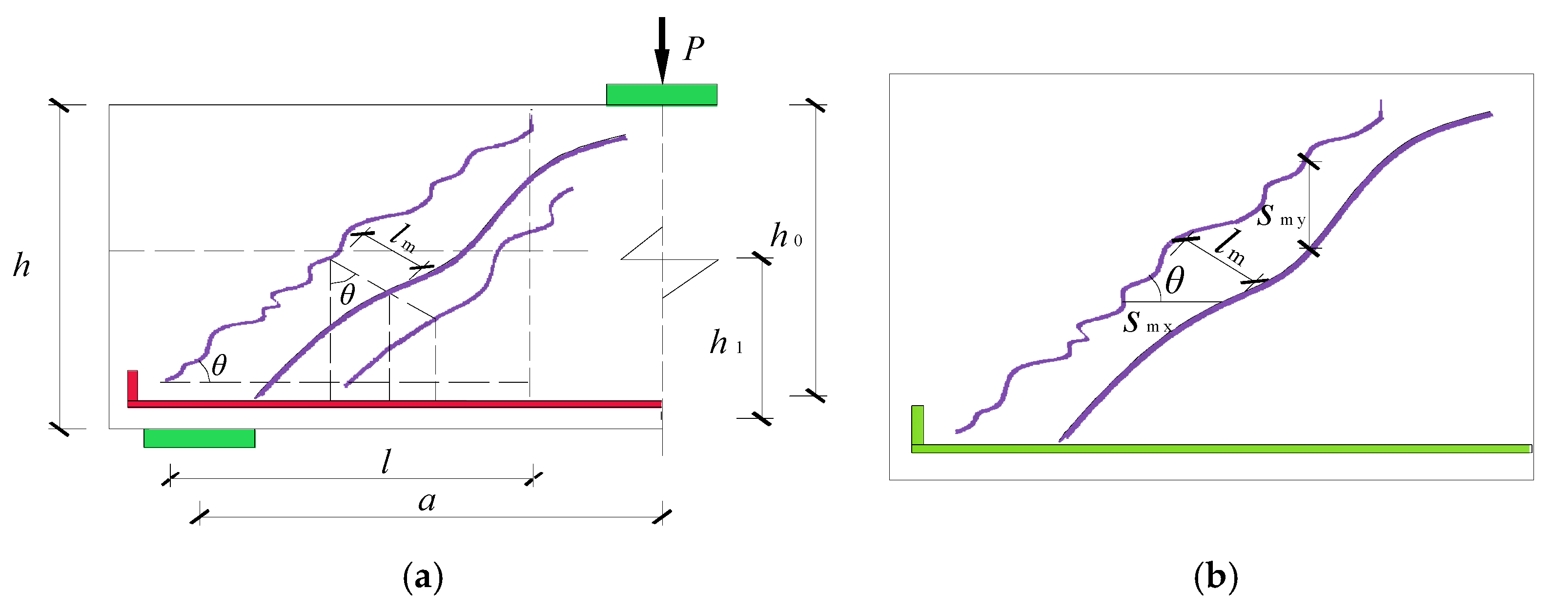
According to the discussion in Section 3.2, the diagonal crack spacing is related to the inclination angle. In the smeared crack model, the complex crack pattern is idealized as a series of parallel cracks also occurring in the vertical direction of the crack pattern, as shown in Figure 8a. It is assumed that the diagonal cracks are uniformly distributed under the condition of a constant crack angle (θ) and crack spacing, as shown in Figure 8b. The diagonal crack spacing is also affected by the crack control characteristics of transverse and vertical bars. Figure 9a,b show the stress mechanism of horizontal and vertical crack formation, respectively.
The average diagonal crack spacing in two orthogonal directions proposed by the CEB-FIP model specification is
l m = 1 sin θ s mx + cos θ s my
where s mx is the average horizontal crack spacing and s my is the average vertical crack spacing. The crack spacing s m can be expressed as
s m = 2 c + s 10 + k 1 k 2 d b p
This expression is used to calculate the crack spacing on the surface of the member, emphasizing the role of the concrete cover. In addition, the expression also takes into account the crack spacing across the shear region and the crack distribution inclined to the direction of reinforcement. However, this formula ignores the fact that diagonal crack spacing decreases with the shear span ratio λ and the effect of the steel skeleton. The steel flange and longitudinal reinforcement jointly constitute the tensile area, and the steel web and stirrup jointly bear the shear effect, as shown in Figure 10a,b. Therefore, Equation (10) can be modified as the following equation:
s mx = 2 c + s x 10 + λ + α k 1 k 2 d x + d w p x + ρ f
s my = 2 c + s v 10 + λ + β k 1 k 2 d v + t w p v + ρ w
where s x is the longitudinal bar spacing; λ is the shear span ratio; α and β are the influence coefficients; α = b f b ; b is the width of the beams; β = d h ; d x is the longitudinal bar diameter; d w is the thickness of the steel flange; ρ f is the amount of the steel flange; ρ f = A f A ef ; A f is the area of the steel flange; A ef is the effective concrete section area; A ef = h 0 b ; h 0 is the effective height of the beam; p x is the amount of the longitudinal bar; p x = A s A ef ; A s is the area of the longitudinal bar; s v is the stirrup spacing; d v is the stirrup diameter; t w is the steel web thickness; p v is the amount of the stirrup; p v = A v b s v ; A v is the area of the stirrup; ρ w is the amount of the steel web; ρ w = A w A ef ; and A w is the area of the steel web.
The proposed modified diagonal crack spacing model considers the existence of steel flanges and steel webs in the SRC deep beam. The total area of the steel in the tension zone consists of longitudinal bars and flanges. The effective concrete section area is introduced. It is the product of the effective height (distance between the center of mass of the tension and the top of the beam) and the width of the section. In addition, the effects of steel web and the shear span ratio are also considered in the modified model. Table 6 shows the comparison of calculated values between the modified model and other models. All comparison results are averages of the experimental data and calculation model. Except for RDB-3, the accuracy of the modified model is higher than that of other models. This is because RDB-3 is relatively large and the crack spacing in the experiment is small, resulting in large error in the comparison results.
The different models [34,35] are proposed for predicting the diagonal crack widths, which are mainly based on the approximately linear proportional relationship between the strain of the shear steel bars and the width of the diagonal cracks. This characteristic is reflected in Formula (2) of the CEB-FIP model specification. Based on the above research results, this article combines the results of Section 3.2 and Figure 8 to further consider the influence of the development of the oblique crack inclination angle. The factor of inclination angle θ , the diagonal crack spacing l m , is introduced into the width calculation formula, and an improved calculation method for the average diagonal crack width ω k can be estimated as follows:
ω k = k w l m ε w
where ε w is the strain of the stirrup, k w is the influence coefficient, and k w = 1.2 .
Figure 11 shows the comparison results between the proposed modified model and the experimental data. In Equation (14), the strain refers to the stirrup strain measured at the crack width location. As shown in the figure, the results calculated using the CEB-FIP model exhibit significant deviations from the experimental values, indicating relatively low accuracy. In contrast, the modified model demonstrates substantially improved computational precision. While the accuracy is slightly lower for smaller crack widths, the theoretical predictions align well with the experimental data as the crack width increases, mostly falling within an 85% confidence interval and showing high reliability.
It should be noted that the modified model proposed in this study was developed based on a relatively limited experimental dataset. Further validation and testing with additional experiments are necessary before considering its application in engineering practice.

5. Conclusions

In this paper, the shear behavior and diagonal crack widths of seven steel-reinforced concrete (SRC) deep beams are investigated, with a focus on key parameters including the shear-span-to-depth ratio, steel flange width ratio, and steel web height ratio. Moreover, the digital image correlation (DIC) technique was used to record the shear test process and evaluate crack initiation and propagation. The following main conclusions could be drawn from the summary of this study:
  • DIC is a suitable tool for evaluating cracking behavior as well as crack development. It can be used for full-field deformation measurements and is useful for the continuous tracking of critical shear cracks. In addition, DIC can accurately record the load at the first crack and can be used to better understand the appearance, development, and final shape of the cracks.
  • When the λ increased from 1.1 to 1.4 and 1.7, the ultimate bearing capacity decreased by 13.3% and 30.4%, respectively. Increasing the section size of the steel skeleton can significantly improve the bearing capacity of the specimens. When the height ratio increases by 0.15 and 0.3, the ultimate bearing capacity increases by 13.7% and 22%, and when the width ratio increases by 0.17 and 0.34, the ultimate bearing capacity increases by 12.8% and 17%.
  • The spacing of diagonal cracks decreases with the increase of the λ . When the λ increased from 1.1 to 1.4, the diagonal crack spacing reduced by 11.3 mm; when the λ increased from 1.4 to 1.7, the diagonal crack spacing reduced by 6.4 mm.
  • The diagonal crack width is mainly affected by the height of the steel web and the λ , and the steel skeleton flange is slightly affected. When the steel skeleton flange width ratio increased from 0.33 to 0.5 and then to 0.67, the average crack width increased by 0.02 mm and 0.05 mm, respectively.
  • The accuracy of the modified model for calculating the diagonal crack width is better than other models. The calculated results are in good agreement with the experimental results. Therefore, the modified model proposed in this paper can be used to estimate the diagonal crack width of an SRC deep beam. However, considering that the research and result verification in this article are based on a limited number of specimen experiments, readers should fully recognize that the effective range and accuracy of the model still need further and more comprehensive demonstration before being applied to practical engineering.

Author Contributions

Writing—review and editing, G.H.; project administration, L.Z.; methodology, B.C.; data curation, S.T. All authors have read and agreed to the published version of the manuscript.

Funding

This research was funded by the National Natural Science Foundation of China (grant numbers 52408141 and 51978078), the Research Support Program Fund of Anhui Polytechnic University (Grant No. 2022YQQ113), the Anhui Province Housing and Urban Rural Construction Science and Technology Plan Project (2023-YF062), and the Anhui Province University Natural Science Research Project (Grant No. 2023AH050918).

Data Availability Statement

Upon reasonable request, datasets generated and/or analyzed during this study may be obtained by contacting the corresponding author.

Acknowledgments

The author expresses sincere gratitude to the relevant personnel who helped with this work and also thanks the peer review experts for their valuable suggestions.

Conflicts of Interest

The authors declare no conflicts of interest.

References

  1. Tong, L.W.; Xiao, S.; He, L.; Zhang, Y.F. Fatigue behavior of steel reinforced concrete (SRC) beams with different shear span-to-depth ratios. Eng. Struct. 2018, 166, 339–353. [Google Scholar] [CrossRef]
  2. Zeng, L.; Xiang, S.; Liu, Y.H.; Chen, J. Experimental study on the dynamic behavior of T-shaped steel reinforced concrete columns under impact loading. Eng. Struct. 2020, 208, 110307. [Google Scholar]
  3. Zeng, L.; Ren, W.T.; Zou, Z.T.; Chen, Y.G.; Xie, W.; Li, X.J. Experimental study on seismic behavior of frame structures composed of concrete encased columns with L-shaped steel section and steel beams. Earthq. Struct. 2019, 16, 97–107. [Google Scholar]
  4. Yue, J.G.; Qian, J.; Beskos, D.E. Seismic damage performance levels for concrete encased steel columns using acoustic emission tests and finite element analysis. Eng. Struct. 2019, 189, 471–483. [Google Scholar] [CrossRef]
  5. Yue, J.G.; Kunnath, S.K.; Xiao, Y. Uniaxial concrete tension damage evolution using acoustic emission monitoring. Constr. Build. Mater. 2020, 232, 117282. [Google Scholar] [CrossRef]
  6. Tong, L.W.; Liu, B.; Zhao, X.L. Numerical study of fatigue behaviour of steel reinforced concrete (SRC) beams. Eng. Fract. Mech. 2018, 166, 339–353. [Google Scholar] [CrossRef]
  7. Wu, K.; Chen, F.; Chen, C.; Zheng, H.; Xu, J. Load-transfer mechanism and bond-stress components in steel and steel fiber–reinforced concrete structure. J. Struct. Eng. 2019, 145, 04019160. [Google Scholar] [CrossRef]
  8. Chen, C.C.; Chen, C.C. Flexural behavior of steel encased composite. J. Chin. Inst. Civ. Hydraul. 2001, 13, 263–275. (In Chinese) [Google Scholar]
  9. Zeng, L.; Xiao, Y.F.; Chen, J.; Chen, Y.G. Quasi-static cyclic test on a concrete-encased frame-reinforced concrete tube building model. Shock Vib. 2018, 2018, 1–14. [Google Scholar] [CrossRef]
  10. Chen, C.C.; Lin, K.T.; Chen, Y.J. Behavior and shear strength of shape reinforced concrete deep beams. Eng. Struct. 2018, 175, 425–435. [Google Scholar] [CrossRef]
  11. Weng, C.C.; Wang, H.S. Shear strength of steel reinforced concrete (SRC) deep beam. J. Chin. Inst. Civ. Hydraul. Eng. 2004, 16, 403–414. (In Chinese) [Google Scholar]
  12. Wight, J.K. Reinforced Concrete Mechanics and Design; Pearson Education South Asia Pte Ltd.: Hoboken, NJ, USA, 2016. [Google Scholar]
  13. Zeng, L.; Cui, Z.; Xiao, Y.; Jin, S.; Wu, Y. Cyclical Behavior of Concrete-Encased Composite Frame Joints with High Strength Concrete. Adv. Mater. Sci. Eng. 2015, 6, 1–13. [Google Scholar] [CrossRef]
  14. Xiao, Y.F.; Zeng, L.; Cui, Z.K.; Jin, S.Q.; Chen, Y.G. Experimental and analytical performance evaluation of steel beam to concrete-encased composite column with unsymmetrical steel section joints. Steel Compos. Struct. 2017, 23, 17–29. [Google Scholar] [CrossRef]
  15. Chen, H.; Yi, W.J.; Hwang, H.J. Cracking strut-and-tie model for shear strength evaluation of reinforced concrete deep beams. Eng. Struct. 2018, 163, 396–408. [Google Scholar] [CrossRef]
  16. Araba, A.M.; Ashour, A.F. Flexural performance of hybrid GFRP-Steel reinforced concrete continuous beams. Compos. Part B-Eng. 2018, 154, 321–336. [Google Scholar] [CrossRef]
  17. Rahal, K.N.; Alrefaei, Y.T. Shear strength of recycled aggregate concrete beams containing stirrups. Constr. Build. Mater. 2018, 191, 866–876. [Google Scholar] [CrossRef]
  18. Demir, A.; Caglar, N.; Ozturk, H. Parameters affecting diagonal cracking behavior of reinforced concrete deep beams. Eng. Struct. 2019, 184, 217–231. [Google Scholar] [CrossRef]
  19. Birrcher, D.; Tuchscherer, R.; Huizinga, M.; Bayrak, O.; Wood, S.; Jirsa, J. Strength and Serviceability Design of Reinforced Concrete Deep Beams; Center for Transportation Research the University of Texas: Austin, TX, USA, 2009. [Google Scholar]
  20. Barris, C.; Torres, L.; Vilanova, I.; Miàs, C.; Llorens, M. Experimental study on crack width and crack spacing for glass-FRP reinforced concrete beams. Eng. Struct. 2017, 131, 231–242. [Google Scholar] [CrossRef]
  21. Lu, W.Y. Shear strength prediction for steel reinforced concrete deep beams. J. Constr. Steel Res. 2006, 62, 933–942. [Google Scholar] [CrossRef]
  22. Comité Euro International Du Béton. CEB-FIP Model Code; Thomas Telford Service Ltd.: London, UK, 1990. [Google Scholar]
  23. Khan, R.M.A.; Shafighfard, T.; Ali, H.Q.; Mieloszyk, M.; Yildiz, M. Strength prediction and experimental damage investigations of plain woven CFRPs with interacting holes using multi-instrument measurements. Polym. Composite. 2015, 44, 3594–3609. [Google Scholar] [CrossRef]
  24. Sabau, C.; Gonzalez-Libreros, J.H.; Sneed, L.H.; Sas, G.; Pellegrino, C.; Täljsten, B. Use of image correlation system to study the bond behavior of FRCM-concrete joints. Mater. Struct. 2017, 50, 172. [Google Scholar] [CrossRef]
  25. Mo, J.X.; Zeng, L.; Liu, Y.; Ma, L.; Cheng, G. Mechanical properties and damping capacity of polypropylene fiber reinforced concrete modified by rubber powder. Constr. Build. Mater. 2020, 242, 118111. [Google Scholar] [CrossRef]
  26. GB/T50107-2010; Standard for Evaluation of Concrete Compressive Strength. China Architecture and Building Press: Beijing, China, 2010. (In Chinese)
  27. GB/228.1-2010; Metallic Materials-Tensile Testing-Part: Method of Test at Room Temperature. Chinese Specification Press: Beijing, China, 2011. (In Chinese)
  28. Ivanov, D.; Ivanov, S.; Lomov, S.; Verpoes, I. Strain mapping analysis of textile composites. Opt. Laser Eng. 2009, 47, 360–370. [Google Scholar] [CrossRef]
  29. Paepegem, W.V.; Shulev, A.A.; Roussev, I.R.; Pauw, S.D.; Degrieck, J.; Sainov, V.C. Study of the deformation characteristics of window security film by digital image correlation techniques. Opt. Laser Eng. 2009, 47, 390–397. [Google Scholar] [CrossRef]
  30. Hassan, H.M.; Farghaly, S.A.; Ueda, T. Displacement at shear crack in beams with shear reinforcement under static and fatigue loadings. Proc. JSCE 1991, 15, 215–222. [Google Scholar] [CrossRef]
  31. Fukuyama, H.; Suwada, H.; Iso, M.; Matsuzaki, Y.; Nakano, K.; Kasahara, M. Evaluation of damage limit state of RC element due to shear crack width. Proc. Archit. Inst. Jpn. 2000, C-2, 13–14. [Google Scholar]
  32. Shinomiya, K.; Watanabe, F. Study on prediction of shear crack width for reinforced concrete beams. Archit. Inst. Jpn. 2002, C-2, 295–296. [Google Scholar]
  33. Piyamahant, S. Shear Behavior of Reinforced Concrete Beams with a Small Amount of Web Reinforcement. Master’s Dissertation, Kochi University of Technology, Kochi, Japan, 2002. [Google Scholar]
  34. Silva, S.D.; Mutsuyoshi, H.; Witchukreangkrai, E. Evaluation of shear crack width in I-shaped prestressed reinforced concrete beams. J. Adv. Concr. Technol. 2008, 6, 443–458. [Google Scholar] [CrossRef]
  35. Zakaria, M.; Ueda, T.; Wu, Z.; Meng, L. Experimental investigation on shear cracking behavior in reinforced concrete beams with shear reinforcement. J. Adv. Concr. Technol. 2009, 7, 79–96. [Google Scholar] [CrossRef]
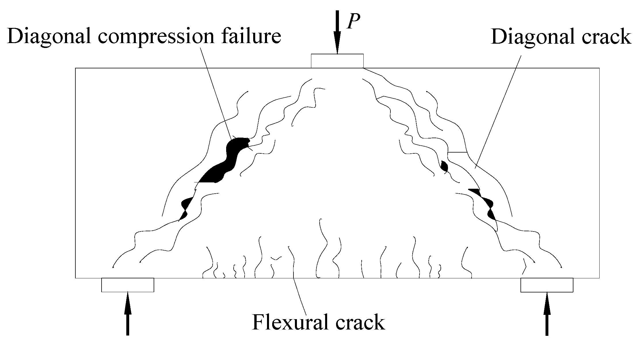
Figure 1. Failure pattern of deep beams.
Buildings 15 01812 g001
Figure 2. Dimensions and reinforcement layout of SRC deep beam (unit: mm).
Buildings 15 01812 g002
Figure 3. Test setup and arrangement of strain gages: (a) setup device; (b) strain gauge arrangement for steel reinforcement skeleton; (c) sensor arrangement; (d) on-site testing; (e) layout of strain gauges for steel beams.
Buildings 15 01812 g003
Figure 4. The crack development pattern and the principal strain contours of the specimens.
Buildings 15 01812 g004
Figure 5. Load–displacement curves of all specimens: (a) shear-span-to-depth ratio; (b) height ratio; (c) width ratio.
Buildings 15 01812 g005
Figure 6. Load–crack width curves of all specimens: (a) shear span-to-depth ratio; (b) height ratio; (c) width ratio.
Buildings 15 01812 g006
Figure 7. Comparison results of theoretical calculation and experimental values. (a) Comparison of partial results of existing models [30,31]; (b) Comparison of results from other models [32,33].
Buildings 15 01812 g007
Figure 8. Development pattern of diagonal cracks: (a) crack development mode; (b) crack size information.
Buildings 15 01812 g008
Figure 9. Idealized crack pattern: (a) longitudinal reinforcement; (b) stirrup.
Buildings 15 01812 g009
Figure 10. Parameters affecting the diagonal crack spacing: (a) Section I; (b) Section II.
Buildings 15 01812 g010
Figure 11. Comparative verification of model calculation results.
Buildings 15 01812 g011
Table 1. Main parameters of SRC beams.
Specimen NumberSpecimen Length (mm) λ Width RatioHeight RatioCross-Section of Steel Size (mm)
RDB-18601.10.50.6192 × 90 × 6 × 8
RDB-210201.40.50.6192 × 90 × 6 × 8
RDB-312001.70.50.6192 × 90 × 6 × 8
RDB-48601.10.50.45144 × 90 × 6 × 8
RDB-58601.10.50.396 × 90 × 6 × 8
RDB-68601.10.670.6192 × 120 × 6 × 8
RDB-78601.10.330.6192 × 60 × 6 × 8
Table 2. Material properties of steel.
Steel TypeThickness or Diameter/mm Yield   Strength   f u /MPaUltimate Strength
fu/MPa
Elastic   Modulus   E s /MPa
HPB30063135342.1 × 105
HRB335184405152.1 × 105
Q23562724062.1 × 105
83154302.0 × 105
Table 3. Loads at the first flexural crack and the first shear crack and the peak load and failure mode of the specimens.
Specimen NumberFirst Flexural
Crack Load (KN)
First Shear
Crack Load (KN)
Peak Load (KN)Failure Mode
RDB-190110788diagonal compression
RDB-260100682diagonal compression
RDB-370130548diagonal compression
RDB-4100120734diagonal compression
RDB-5100130645diagonal compression
RDB-6110160816bearing
RDB-760100698diagonal compression
Table 4. Diagonal crack spacing.
Specimen NumberMinimum Spacing
(mm)
Maximum Spacing (mm)Mean Spacing (mm)
RDB-1298256.4
RDB-2217445.1
RDB-3206238.7
RDB-4277248.3
RDB-5327146.9
RDB-6337857
RDB-7206435.8
Table 5. Diagonal crack width.
Specimen NumberMinimum Width
(mm)
Maximum Width
(mm)
Mean Width
(mm)
RDB-10.121.430.9
RDB-20.151.170.76
RDB-30.101.040.68
RDB-40.120.960.59
RDB-50.160.630.27
RDB-60.141.610.93
RDB-70.131.520.88
Table 6. The experimental value is compared with the calculated value (ratio cal–exp).
Model RDB-1RDB-2RDB-3RDB-4RDB-5RDB-6RDB-7
CEB-FIP Model Code0.630.480.850.580.670.600.72
Shinomiya0.570.510.780.480.640.560.49
Piyamahant0.430.470.740.610.780.650.64
Modified model0.870.820.770.850.860.910.88
Disclaimer/Publisher’s Note: The statements, opinions and data contained in all publications are solely those of the individual author(s) and contributor(s) and not of MDPI and/or the editor(s). MDPI and/or the editor(s) disclaim responsibility for any injury to people or property resulting from any ideas, methods, instructions or products referred to in the content.