Article

Zigzag Reinforcement Method for 3D Concrete Printing

by
Bahram Ahadi
and
Mercedes Valiente López
*
Escuela Técnica Superior De Edificación, Universidad Politécnica de Madrid, 28040 Madrid, Spain
*
Author to whom correspondence should be addressed.
Buildings 2025, 15(10), 1721; https://doi.org/10.3390/buildings15101721
Submission received: 20 April 2025 / Revised: 11 May 2025 / Accepted: 14 May 2025 / Published: 19 May 2025
(This article belongs to the Section Building Materials, and Repair & Renovation)

Abstract

Three-Dimensional Concrete Printing (3DCP) is transforming the construction industry by offering faster, more cost-effective, and sustainable building solutions. However, a major challenge that hinders its full potential is the low tensile strength of concrete, which, as in conventional methods, necessitates reinforcement. Unlike traditional construction, integrating reinforcement into the automated 3D printing process is complex and remains a critical research gap. In this study, zigzag-reinforcing method, that could be classified as an in-process interlayer reinforcement in 3DCP, is proposed. To investigate the effect of the proposed reinforcement technique, an analytical study was conducted using Abaqus finite-element software. Four beam models with different reinforcement configurations were considered: an unreinforced control specimen, two Nitinol-reinforced beams (one exhibiting superelastic behavior and the other the shape memory effect), and a steel-reinforced beam. Three-point bending tests were simulated using a displacement-controlled, centrally applied load. The results showed that zigzag reinforcement improved flexibility and prevented sudden failure. The Nitinol-reinforced sample with superelastic behavior failed at a displacement of 2.67 mm, approximately 37 times greater than the 0.07 mm failure displacement of the unreinforced beam. Unlike the unreinforced specimen, where cracks propagated vertically, the zigzag reinforcement redirected crack propagation horizontally, allowing the beams to carry more load. Additionally, the steel-reinforced sample demonstrated a 68% increase in maximum flexural moment and a 286% increase in flexibility compared to the control specimen. Overall, zigzag reinforcement significantly enhanced the mechanical performance of the samples, and if its durability and other practical parameters are validated through experimental studies, it could be considered a promising reinforcement technique for use in 3D concrete printing.

1. Introduction

The expansion of the construction sector is significantly impeded by various intricate challenges, including cost and schedule overruns, occupational health and safety risks, reduced productivity, and workforce shortages [1,2]. Moreover, construction remains one of the least digitized industries globally, which has exacerbated its difficulty in overcoming these persistent issues [3]. The time required to construct structures using conventional methods has resulted in this industry having the lowest efficiency rate compared to other sectors [4].
In response to these limitations, in recent years, significant efforts have been made to adapt digital production techniques from other industries to the construction sector [5,6]. Automation is progressively being integrated into various components of construction, offering improvements in precision while concurrently minimizing the duration of the construction process. Among these, Three-Dimensional Concrete Printing (3DCP), a form of additive manufacturing, has emerged as a promising solution. Leveraging digital modeling and automated material deposition, 3DCP offers the potential to reduce construction time, minimize material waste, and increase design flexibility. Concrete 3D printing, also known as additive manufacturing, is fundamentally reliant on digital modeling and automated control systems. This technique involves the sequential deposition of material in layers, either through extrusion or spraying, from the base upward until a complete structural form is realized. The application of 3D printing technology in the construction of buildings has seen a steady increase in recent years [7].
However, despite its promise, 3DCP remains in a developmental stage and faces several technical and structural limitations. Since the development of the first 3D printer in 1983, the advancement of this technology has progressed at an accelerated pace [8,9]. Among the most pressing challenges are the lack of standardized design codes, difficulties in structural reinforcement, and constraints related to the scalability of multi-story construction. In particular, the integration of reinforcement into the 3D printing process, poses a significant barrier to the structural viability of printed buildings. Unlike conventional construction, where reinforcement is embedded manually during casting, the automated and layered nature of 3DCP demands innovative reinforcement strategies that can be seamlessly incorporated into the printing process. Buswell et al. [
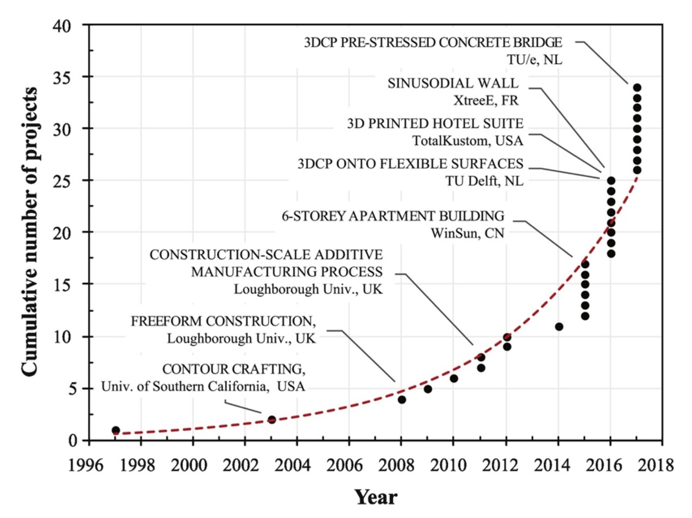
10] studied 3DCP research opportunities and presented the growth of additive manufacturing in construction applications since 1996 as it is presented in Figure 1.
The diagram highlights the exponential growth of 3D concrete printing (3DCP) projects from 1996 to 2018, with a significant rise after 2010. Early developments were led by research institutions, but recent years show a shift toward large-scale, real-world applications such as multi-story buildings and complex structures. This trend reflects increasing global interest, technological advancement, and the need for further research—especially in areas like reinforcement—to support the structural integrity and broader adoption of 3DCP in construction.
This research addresses one of the critical missing pieces in the 3DCP puzzle: a practical, in-process reinforcement method that enhances structural performance without compromising automation. By developing and simulating a novel zigzag-shaped interlayer reinforcement technique, this study contributes a first-of-its-kind approach aimed at increasing both the flexural strength and ductility of 3D printed elements. The effectiveness of the method is evaluated using advanced finite-element modeling and explores the use of both conventional (galvanized steel) and smart materials (Nitinol shape memory alloy).
Ultimately, this research aims to bridge a crucial gap between material innovation and construction automation, bringing the industry closer to realizing safe, resilient, and sustainable structures through 3DCP. By advancing reinforcement strategies, this work contributes to the broader goal of delivering affordable housing, rapid emergency shelters, and environmentally conscious infrastructure, benefiting not only the construction field but society as a whole.

1.1. Materials in 3D Concrete Printing

Like conventional concrete, 3D concrete printing (3DCP) is predominantly composed of cement paste and aggregates [11,12]. Given the specialized nature of 3DCP technology, achieving optimal performance in printing materials is crucial. The material must simultaneously exhibit sufficient fluidity to facilitate uninterrupted flow through the pipeline and extrusion through the nozzle, while also demonstrating adequate structural stability to allow for successful layer-by-layer stacking without deformation or collapse [11,13,14,15]. Nevertheless, one of the primary challenges encountered in 3DCP is the clogging of the printing material during the construction process [10,16,17,18]. In traditional concrete applications, high workability, extended slump retention, enhanced passing ability, and delayed setting are generally desirable. However, in the context of 3D concrete printing, a lower workability with rapid setting immediately after extrusion is necessary to ensure print stability [19,20,21]. Unlike conventional casting methods, 3DCP does not rely on mechanical compaction; instead, material agitation occurs solely during the mixing and pumping stages [19]. Rheology is defined as the study of the way in which materials deform or flow in response to applied forces or stresses [22]. Generally, these key materials and additives improve the rheological behavior of the 3DCP: superplasticizer [23], viscosity-modifying agents [24,25], fiber reinforcements [26], nanomaterials [27,28], mineral and chemical admixtures [29], gradation of aggregates [30], and controlled water-cement ratio.

1.2. Reinforcement in 3D Concrete Printing

A significant challenge in 3D concrete printing (3DCP) is the effective incorporation of reinforcement, which is critical for enhancing both the mechanical performance and durability of printed structures. Conventional reinforcement methods, such as steel bars and fibers, are generally incompatible with the layer-by-layer construction technique employed in 3DCP. Within the realm of 3DCP, reinforcement plays a vital role in improving the ductility and tensile strength of printed concrete [31,32]. Ductility, in the context of 3D concrete printing, refers to the material’s capacity to deform and elongate without experiencing cracking or failure. This property is particularly essential for printed structures, as they must endure various loading conditions, including self-weight and external forces. Reinforcement strategies in 3DCP can be categorized into three main approaches: (I) pre-installed reinforcement [33,34], (II) post-installed reinforcement [35], and (III) in-process reinforcement. The in-process reinforcement method enables the simultaneous and automated execution of both printing and reinforcement. Various techniques have been developed for this approach, including the deposition of U-nails between layers [36], the incorporation of reinforcing bars [37], meshes [38], fibers [39], and geometric optimization to reduce reinforcement. Hojati et al. [40] proposed use of barbed wires as the reinforcing material in 3DCP.
This study aims to introduce a novel in-process reinforcement method for 3DCP that is compatible with existing printing systems while also improving the mechanical performance of printed structures. The proposed reinforcement technique involves embedding zigzag-shaped wires within the printed layers, allowing for simultaneous deposition during the printing process. To evaluate the impact of incorporating zigzag-shaped wires in 3DCP, an analytical study was conducted, wherein multiple samples were simulated and analyzed using the Abaqus finite-element software.

2. Background and State of the Art

The literature review in this paper focused on in-process reinforcement methods that have been investigated by researchers. Given the proposed reinforcement method in this study, related studies provide insight for readers regarding the effectiveness of the zigzag reinforcement strategy.
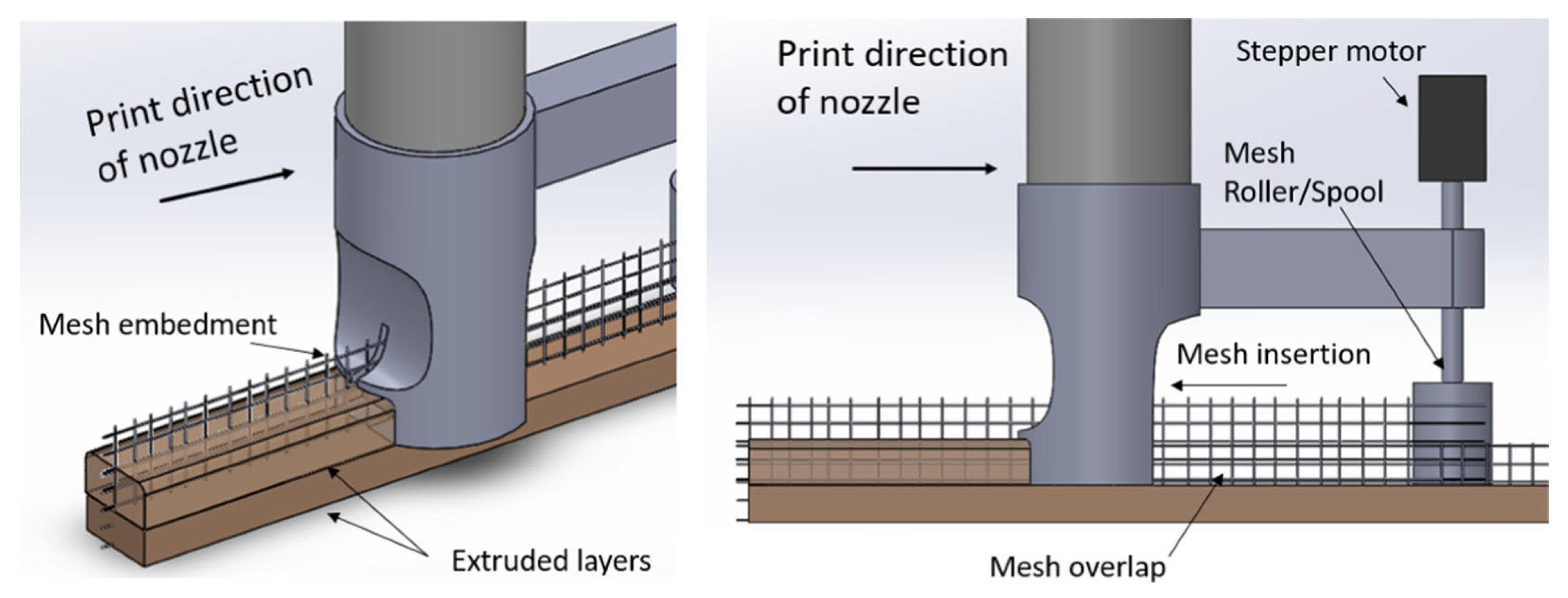
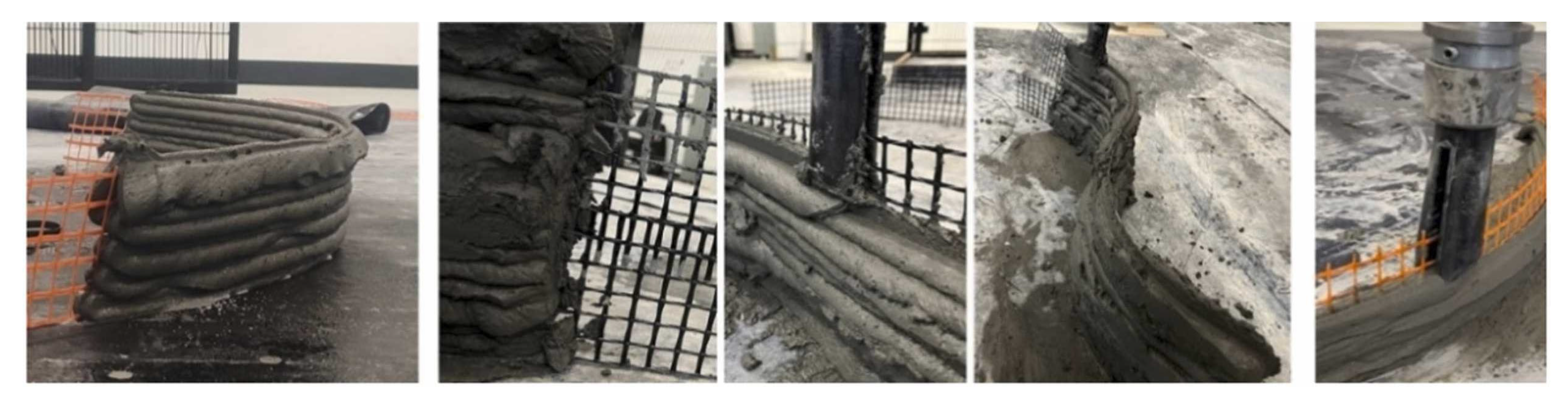
In 2019, Marchment et al. [38] proposed a novel in-process reinforcement method in which steel meshes were used to create interlayer reinforcement as it is shown in Figure 2. Three-point bending tests were conducted on both reinforced and unreinforced printed samples. Their proposed reinforcement method enhanced the flexural moment strength by 170% to 290%.
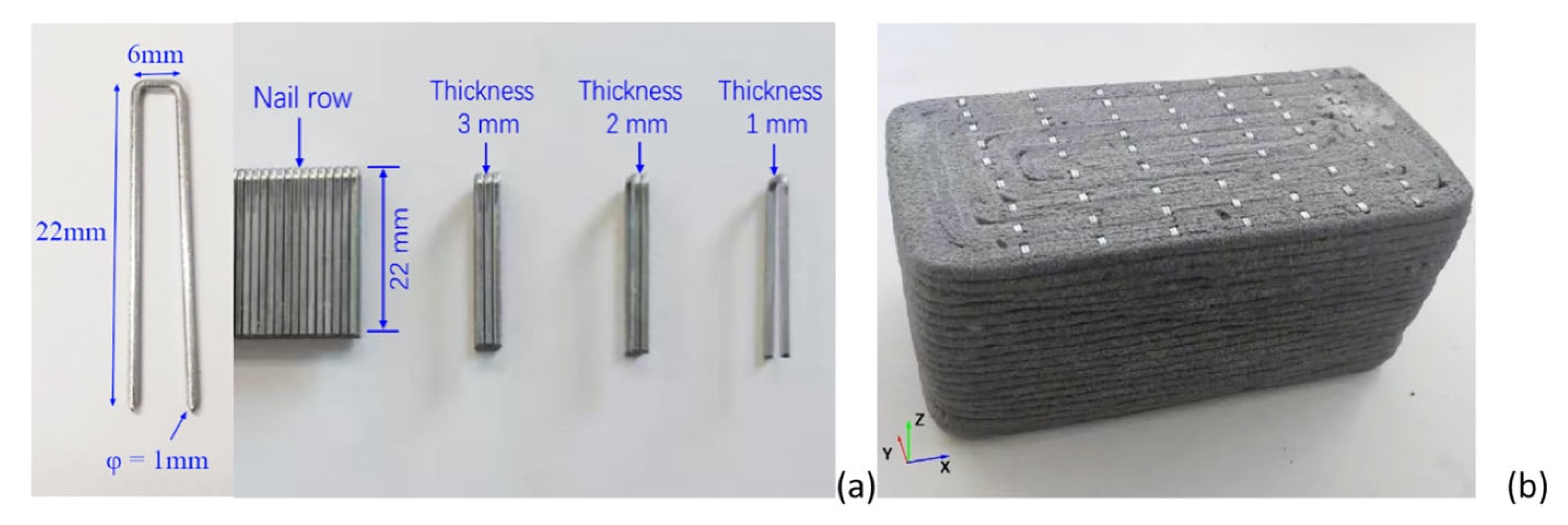
In 2020, Wang et al. [36] conducted an experimental study to investigate interlayer reinforcement of 3D printed concrete through the in-process deposition of U-nails due to Figure 3. They prepared both reinforced and unreinforced samples for tensile and double shear tests. Figure 3 shows shape and configuration of U-nails and the printed sample reinforced with U-nails.
In the interface tensile tests, the tensile strength increased with an increase in U-nail thickness and decreased with greater U-nail spacing. Increasing the U-nail spacing from 20 mm to 40 mm reduced the tensile strength for U-nails with thicknesses of 1 mm, 2 mm, and 3 mm by 42.8%, 49.3%, and 38.9%, respectively. Increasing the U-nail thickness from 1 mm to 3 mm resulted in a tensile strength increase of 26.3% to 35.3%. In the interface shear tests, it was observed that for U-shaped nails with thicknesses of 1 mm, 2 mm, and 3 mm, the shear strength decreased by 34.6%, 22.1%, and 24.5%, respectively, when the spacing interval increased from 20 mm to 40 mm.
The vast majority of investigations into the reinforcement of 3D printed concrete (3DPC) have focused on the use of discrete fibers as reinforcement [33,41]. Several experimental studies have been conducted to examine the effect of short fibers on the 3DCP mix design. Hambach and Volkmer [39] studied the effect of carbon, glass, and basalt fibers, each with lengths ranging from 3 to 6 mm, in a 3D printed composite of Portland cement paste. They observed that the flexural and compressive strengths of the samples increased up to 30 MPa and 80 MPa, respectively. They also found that the samples reinforced with glass and basalt fibers exhibited lower flexural strength compared to those reinforced with carbon fibers, which was attributed to the lower Young’s modulus values of glass and basalt fibers. 
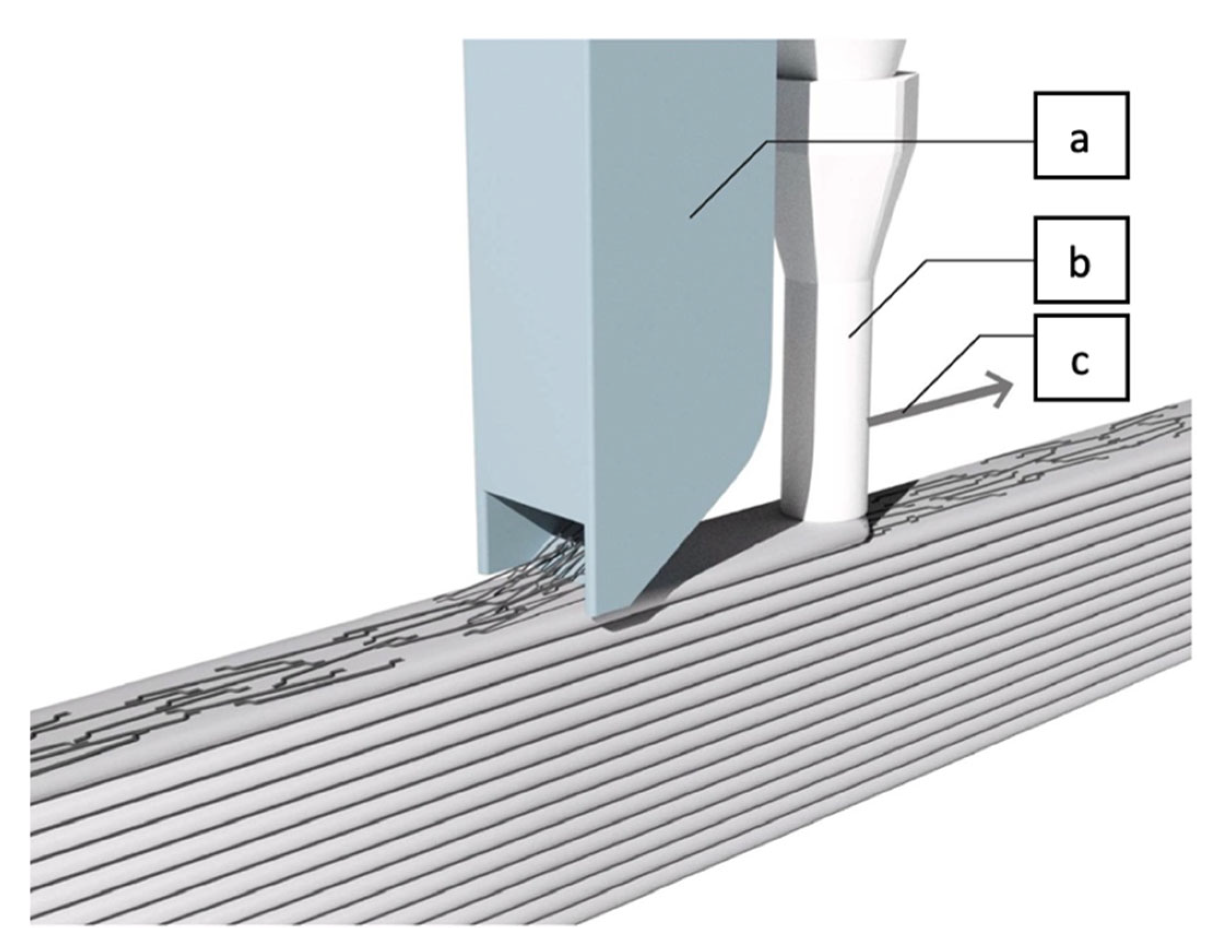
Figure 4 shows the mechanism of aligned fiber reinforcement which was proposed by Gebhard et al. [42] and investigated by Ahmed et al. [33].
Arunothayan et al. [43] studied several key aspects related to the use of 3D printing for creating ultra-high performance concrete (UHPC) structures reinforced with steel fibers. Their primary focus was to understand how the 3D printing process influences the alignment of these fibers and the subsequent impact on the concrete’s mechanical performance. They found that the 3D printing process leads to a preferential alignment of steel fibers in ultra-high-performance concrete along the printing direction due to the extrusion forces. Smaller nozzle sizes and higher fiber volume fractions during printing enhance this alignment. Specifically, a 10 mm nozzle resulted in approximately 30% higher fracture strength compared to a 40 mm nozzle. The printing speed did not significantly affect the fiber alignment and this directed fiber alignment in 3D-printed UHPC resulted in improved mechanical performance, particularly in flexural strength, compared to conventionally mold-cast UHPC. For a 3% fiber content, fracture strength increased by about 40% in printed samples.
Ramesh et al. [44] investigated the potential of using textile reinforcement in 3DCP. They modified the printing nozzle and incorporated reinforcing textiles during the printing process. They concluded that the use of glass textiles enhanced the load-carrying capacity by approximately 60%, and the deflection at failure for the printed specimens was significantly higher compared to the mold-cast specimens. Figure 5 shows the modified nozzle and printed reinforced sample by the proposed method of Ramesh et al. [44].
In another paper, Ramesh et al. [45] investigated the dynamic behavior of textile-reinforced 3D printed concrete panels under impact loading. Specifically, they evaluated the impact resistance, energy absorption capacity, and failure patterns of 3D printed concrete panels reinforced with two different types of textiles: alkali-resistant glass (AR-glass) and carbon. The panels were subjected to multiple impacts from different drop heights (1 m and 2 m) to assess their response. The authors found that using carbon textile reinforcement improved the impact load and energy absorption of the 3D printed concrete panels, leading to controlled failure and crack propagation. They also observed that textile reinforcement generally enhanced the damage distribution by improving the bridge between the printed layers.
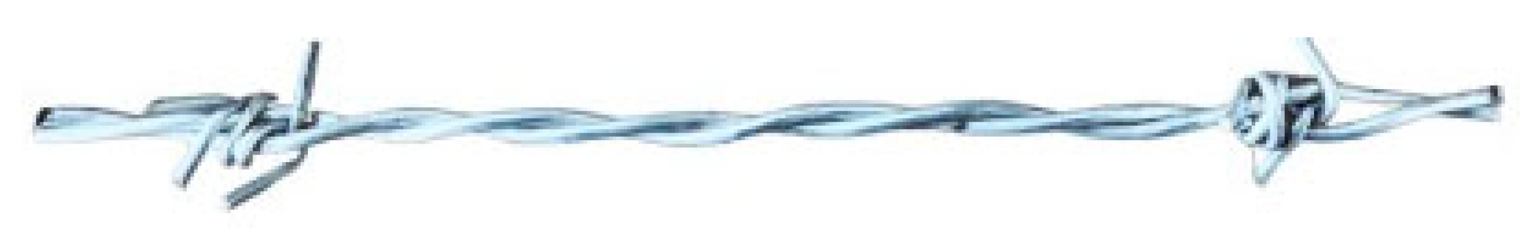
Hojati et al. [40] investigated the moment capacity of printed samples reinforced with barbed wires. Their proposed reinforcement type is presented in Figure 6. They tested the samples under three-point bending and concluded that the moment capacity of the reinforced samples increased by 400% to 1300% with the use of barbed wires.
Hau Bong et al. [46] investigated the formulation and properties of a 3D-printable strain-hardening alkali-activated composite (3DP-SHAAC or 3DP-SHGC) for use in additive construction. Their research involved first identifying an optimal binder matrix by testing different ratios of fly ash to slag for rheological properties and compressive strength. This optimized matrix was then reinforced with PVA fibers to create the 3DP-SHAAC/SHGC. The printability and rheological properties of this composite were evaluated. The study also examined how curing temperature affects the compressive, flexural, and tensile performance of printed samples, comparing them to conventionally cast samples. The key findings showed that the 3D-printed composite had better flexural performance and higher tensile strength than the cast specimens, with comparable tensile strain capacity. The curing temperature was found to significantly influence the mechanical properties of both printed and cast composites. The authors conclude that this “just-add-water” binder simplifies the process and enhances safety compared to traditional alkali-activated materials.
Current in-process reinforcement techniques in 3D concrete printing face several limitations that hinder their widespread use. Automation remains a significant challenge, particularly for long reinforcing bars which can bend or vibrate during printing, and for precise placement of vertical reinforcement. Bond strength between the reinforcement and the concrete matrix is another critical issue, with smooth cables and inserted elements often suffering from poor adhesion and potential void formation. Furthermore, geometric constraints imposed by the printer nozzle and the reinforcement’s physical dimensions limit the size and type of reinforcement that can be integrated. Material compatibility can also be problematic, with fibers potentially clogging the nozzle or altering the concrete’s flow properties. Finally, many existing methods struggle to provide effective reinforcement in multiple directions, especially across the weak interfaces between printed layers.
Our proposed zigzag wire reinforcement method has the potential to improve upon these limitations in several ways. The zigzag shape is expected to enhance mechanical interlocking and bond strength with the concrete due to the increased surface area and physical keying effect. The vertical segments of the zigzag pattern can also act as shear connectors, improving load transfer and bonding between printed layers, addressing the weakness at these interfaces. The inherent flexibility of wires suggests a higher potential for automated embedding, either through printhead modifications or auxiliary robotic systems. Moreover, the use of Nitinol SMA wires introduces advanced functionalities like self-healing and enhanced seismic resistance, which are not offered by traditional reinforcement methods.

3. Methodology

3.1. General Methodology

In this study, reinforcement in 3D concrete printing (3DCP) was investigated, and existing reinforcing techniques were reviewed. Enhancing ductility, alongside other mechanical parameters, was identified as the key objective of this investigation. A novel in-process reinforcement method for 3DCP using a smart material was proposed for the first time in this study. The mechanical behavior of the reinforced samples, including ductility, moment resistance in flexure, and energy dissipation, was analyzed through an analytical study.
Abaqus finite-element software was used to simulate the samples based on experimental studies reported in the literature. As a first step, existing similar reinforcement methods proposed and analyzed by other researchers were identified and discussed in detail. Next, relevant experimental studies were used to validate our software simulations and ensure that the simulated behavior closely matched real experimental results.
In the second step, material properties were extracted from the literature and used as input parameters in the software simulation. It should be noted that the validation process was presented in our previous publications [6,12,15,32,41].
In the next step, different samples with different reinforcing materials were analyzed under three-point bending tests and results were extracted and discussed.

3.2. Specific Methodology

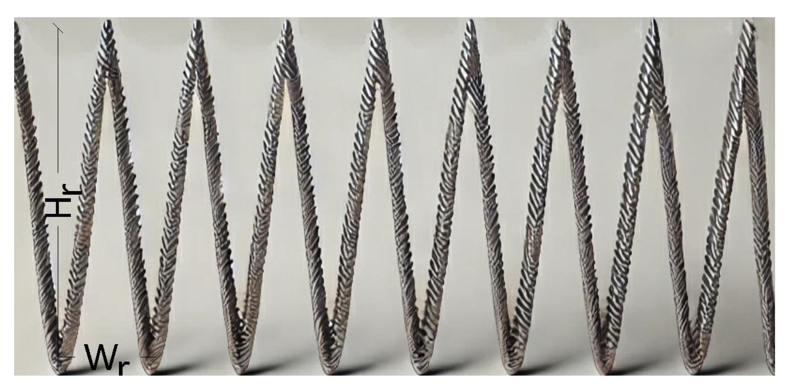
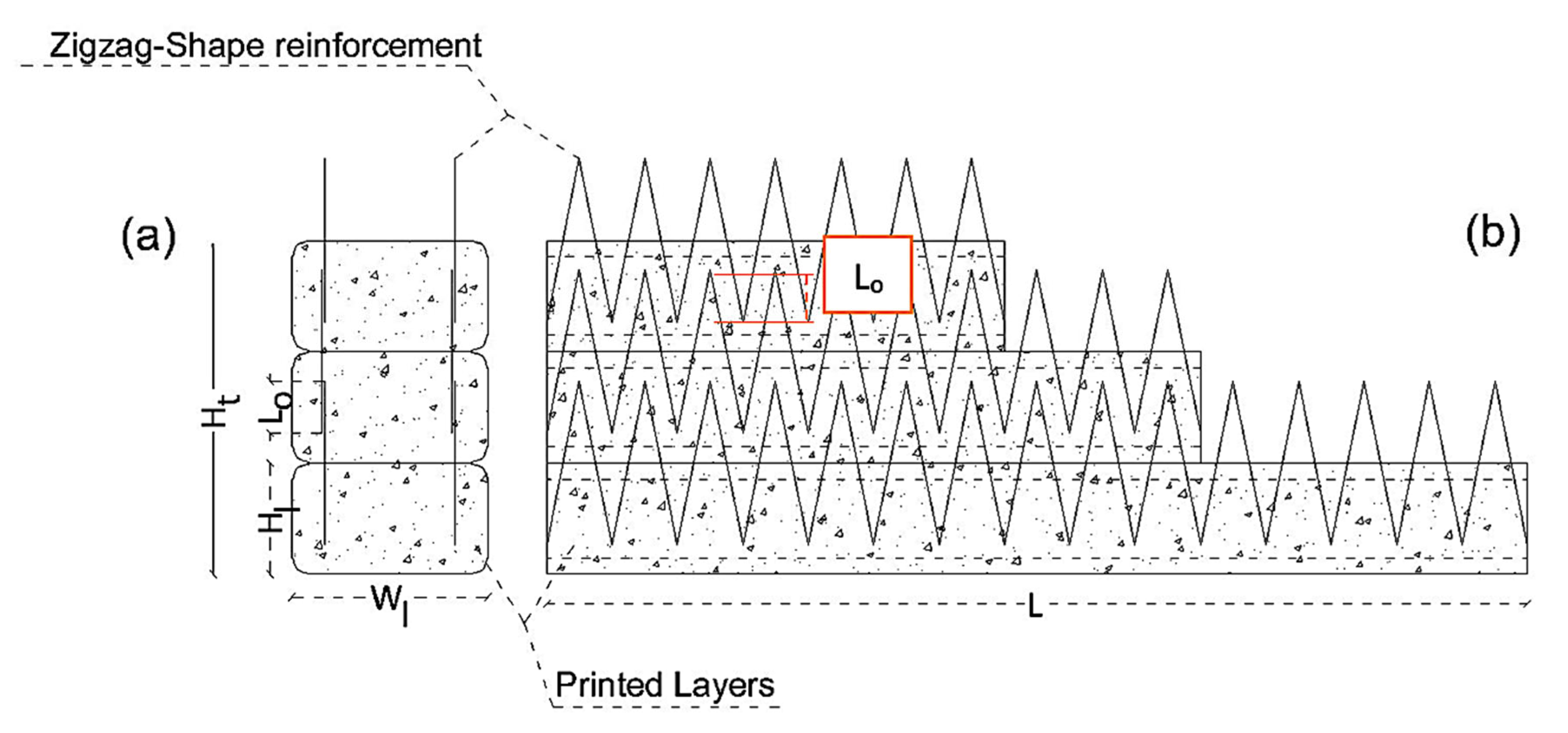
In this study, a new in-process reinforcing technique using a smart material for 3DCP was proposed. The proposed method is based on incorporating zigzag-shaped wires, which could be embedded in the printed layers during the printing process, providing interlayer reinforcement that connects successive layers in addition to the concrete adhesion. The zigzag-shaped reinforcement was selected based on several functional and practical criteria relevant to 3DCP. First, the geometry offers enhanced mechanical interlock across printed layers, which are known to be critical weak planes in layered fabrication. Unlike straight or vertically inserted reinforcements, the zigzag layout provides continuous anchorage along both horizontal and vertical directions, improving bonding with the surrounding concrete and resisting crack propagation. Second, this shape accommodates the layer-by-layer deposition process, allowing either manual or automated placement during printing without disrupting the nozzle path. Third, the angular bends in the zigzag wire introduce beneficial confinement and flexural resistance by inducing distributed stress transfer zones. Figure 7 and Figure 8 schematically show the shape of the unique reinforcement and the placement of the reinforcing material within the printed layers.
In Figure 7 and Figure 8, the parameters Wr, Hr, Wl, Lo, Hl, L, and Ht are defined as follows:
Wr: width of a single step in the zigzag reinforcement
Hr: height of the reinforcement material
Wl: width of a single printing layer
Hl: height of a single printing layer
Lo: length of the overlap of reinforcement between sequent layers
L: length of the printed layers
Ht: total height of printed layers
In this reinforcing method, the zigzag-shaped wires are placed on top of each printed layer and overlap with the upper and lower layers by a length of Lo to provide continuous reinforcement. To investigate the effectiveness of this reinforcing technique, an analytical study was conducted. Abaqus finite-element software was used to simulate both unreinforced and reinforced samples, which were analyzed under three-point bending tests. Results such as moment-deflection diagrams and failure mechanisms were extracted. In Figure 8, the overlap of the zigzag reinforcements can be observed. Figure 9 and Figure 10 show a 3D view of the proposed method with three concrete layers and the embedded reinforcing materials.

4. Software Simulation

To simulate and analyze the samples, Abaqus CAE version 2024 was used. In this software, the specimens are discretized into small finite elements, enabling detailed analysis. The strain and stress distributions within the elements can be examined, and the performance of the reinforcement under the applied loads can be observed.

4.1. Samples’ Geometric Properties

The first step in simulating the samples was to define the geometric properties of the specimens in the Part module. In this study, the width and height of each individual concrete printing layer were considered to be 30 mm and 17 mm, respectively, based on experimental studies in the literature [36,38,47]. Figure 11 shows the section view of a single printing layer.
Regarding the interlayer reinforcement in the proposed method, the samples were analyzed under a load applied parallel to the direction of the layers. In this case, it was necessary to consider the length of the successive printed layers. Based on the experimental study by Marchment et al. [38], nine concrete sequent layers with each single length of 45 mm were considered due to Figure 12, and finally a concrete beam with the dimensions of 45 mm × 30 mm × 153 mm was studied under the three-point bending test as it is shown in Figure 13.
To apply the load smoothly and reduce stress concentration in the support areas, circular rigid elements were defined. The free span of the specimens was set to 140 mm in the tests. The reinforcement used in this simulation had a height of 25 mm and a width of 10 mm in each of its steps. The selected height of the zigzag-shaped wires (Hr = 25 mm) corresponds to the thickness of the printed concrete layers and is designed to ensure vertical overlap (Lo) with the reinforcement in the subsequent layer, thereby achieving a continuous reinforcement network throughout the height of the printed element. Each horizontal step of the zigzag (Wr = 10 mm) was chosen to create a sufficiently sharp angle, which facilitates penetration into the fresh concrete with minimal disturbance to the layer interfaces. This geometry also enhances the mechanical interlock between the reinforcement and concrete matrix. Increasing Hr while maintaining a relatively small Wr effectively increases the bonded surface area, contributing to improved load transfer and crack-bridging capacity. However, the optimization of these geometric parameters, including pitch, amplitude, and angle, remains an open area for future investigation, particularly in terms of balancing mechanical performance with printability and process integration. Table 1 shows a summary of the geometric properties of the considered samples.

4.2. Material Mechanical Properties

The use of accurate material mechanical properties is one of the most important stages in software simulation of any engineering phenomenon, as it directly affects the results. Materials should be modeled using validated models and verified through experimental studies. In this research, concrete was used as the material for the host component, while steel and Nitinol shape memory alloys (Nitinol-SMA) were used as the reinforcing materials within the concrete object. All material properties used in this study were based on experimental studies in the literature and were verified in terms of mechanical behavior and failure modes.

4.2.1. Concrete

The general characteristics of concrete that can be used in 3DCP, such as its rheological properties and material composition, were explained in Section 1.2. It is known that concrete is an anisotropic material, and especially in 3DCP, the mechanical properties of printed samples in the direction parallel to the layers differ from those in the direction perpendicular to the layers. In this investigation, the load was applied to the considered beam in the direction parallel to the layers, and it was assumed that the beam did not experience any lateral displacement during the test. The mechanical properties of concrete were defined only in the direction parallel to the layer’s orientation. The properties of concrete defined in Abaqus are shown in Table 2.
The dilation angle represents the volumetric expansion due to plastic deformation of concrete. Essentially, the dilation angle represents the correlation between volumetric strain and shear strain, as indicated by Equation (1): Dilation angle [48,49,50,51].
Ψ = δ ε v δ v
where:
δ ε v is the shear strain, and
δ v is volumetric strain.
Larger Ψ leads to behavior resembling that of ductile material and smaller Ψ results in more brittle material behavior; it varies between 30° and 40° for concrete simulations [48].
Eccentricity controls the shape of the flow potential. The default flow potential eccentricity is 0.1, which implies that the material has almost the same dilation angle over a wide range of confining pressure stress values [48,52,53,54].
fb0/fc0 defines the relationship between biaxial and uniaxial compressive strengths [48].
K is the ratio of the second stress invariant on the tensile meridian to that on the compressive meridian at initial yield. It reflects the difference in behavior of concrete under tension and compression. This parameter is also typically obtained from experimental data [48,55].
The viscosity parameter is a value used to regularize the constitutive equations by introducing a small amount of viscous behavior. This helps improve numerical convergence during analysis, particularly when dealing with softening material behavior, such as cracking in concrete. Essentially, it acts as a stabilization factor to prevent excessive localized deformation in the damage zone [48,52,55].
Concrete compression and tension damage can be seen in Table 3 and Table 4.
To simulate the concrete element, it was assumed that the concrete behaves as a single, continuous material rather than as separate layers. The material properties were applied to the entire element, considering the minimum resistance of the concrete, which occurs in the connection areas between layers. This assumption was made to simplify the analysis process. Figure 14 shows the simulated concrete sample in Abaqus area.
It should be noted that the partition considered in the midspan area is due to the use of smaller mesh sizes to obtain more precise results, particularly in the midspan of the beam.

4.2.2. Steel

After defining concrete as the primary and host material in the simulation, the reinforcing materials were specified. Galvanized steel and Nitinol-SMA were used as the reinforcement in this study. The mechanical and plastic properties of steel, extracted from the experimental study by Marchment et al. [38], are presented in Table 5 and Table 6. Both the steel and Nitinol zigzag wires had a diameter of 0.5 mm.

4.2.3. Nitinol Shape Memory Alloy

Shape Memory Alloys (SMAs) are unique materials with the fascinating ability to recover apparent permanent deformation of up to 10% or more [56]. This remarkable property, along with other characteristics such as high strength, stiffness, corrosion resistance, and workability—similar to conventional metals—makes SMA a modern and programmable material used in various industries, including civil engineering, aerospace engineering, medicine, and robotics. Aortic stents and orthodontic wires are among the most well-known applications of SMAs, demonstrating their integration into everyday life. To introduce SMA simply, consider that when a shape memory alloy deforms under an external load, it can restore its original shape upon heating. For example, if an SMA is stretched at low temperatures, it can recover its original shape (a shorter length) when heated. This property provides SMAs with a significant advantage over conventional metals. Unlike typical metals, which remain in a passive state, SMAs can function as both sensors and actuators.
The two unique characteristics of SMAs are the Shape Memory Effect (SME) and Superelasticity (SE). SME enables the material to return to its original shape when heated after deformation, while SE allows the material to be bent or stretched significantly and still return to its original shape upon unloading. SME alloys can restore their original shape in a particular temperature; this is the reason why they can be used as actuators. Figure 15 shows forms of stress-strain curve for SME and SE.
Nitinol that is composed of nickel and titanium (Ni-Ti) is the most famous alloy in SMAs due to its best shape memory characteristics together with three other remarkable properties, like an excellent corrosion resistance, a very stable configuration, and fatigue behavior [56]. The mechanical and superelastic properties of Nitinol-SMA, which was used in this study as the reinforcing material, are presented in Table 7 and Table 8. These properties were adopted based on the experimental study conducted by Bykiv et al. [58].
Figure 16 indicates embedded reinforcements in the concrete element in the Abaqus area.

4.3. Other Analysis Parameters

After defining the material properties, the components such as concrete, reinforcements, supports, and load rigid elements were assembled, as shown in Figure 14 and Figure 16. It should be noted that the reinforcements had a cover of 5 mm, as can be seen in the section view of the reinforced sample in Figure 17. Interaction between the reinforcements and concrete was defined using the “embedded region” option in the Interaction module. Subsequently, the support conditions were defined. One of the supports was fixed by displacements in the X, Y, and Z directions, while the other support was fixed in the Y and Z directions, allowing the sample to experience free displacement in one direction due to the three-point bending test mechanism.
The load applied to the samples was a displacement-controlled load and was applied as a concentrated force at a reference point, which was defined in the load rigid element. Afterward, the sample was meshed with a 3 mm element size in the midspan region and a 5 mm element size in other areas. In total, four specimens were created and analyzed. Table 9 presents the characteristics of the specimens.
In Table 9, SRS represents the Steel-Reinforced Sample, SMARS-SE refers to the Nitinol-SMA-Reinforced Sample analyzed with the superelasticity behavior of SMAs, and SMARS-SME represents the Nitinol-SMA-Reinforced Sample analyzed with the shape memory effect (SME) behavior of SMAs. URS stands for the Unreinforced Sample, which contained no reinforcing material and served as a reference prototype to evaluate the effectiveness of the zigzag-reinforcement strategy.
It should be noted that in the analysis of the SMARS-SME specimen, the zigzag wires were subjected to a 560 N recovery force. This force was applied in the initial step of the analysis to simulate the shape recovery behavior of Nitinol.

5. Results and Discussion

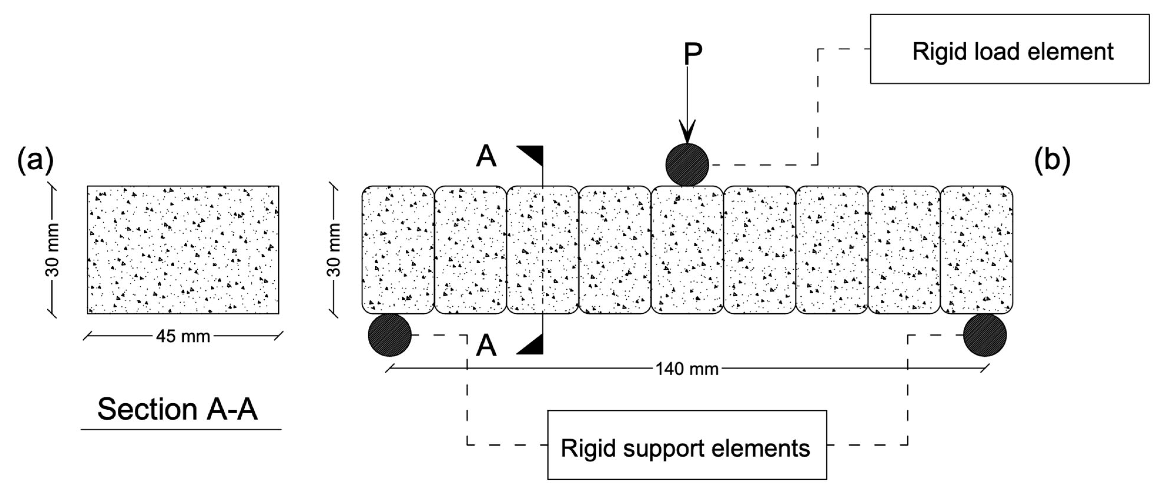
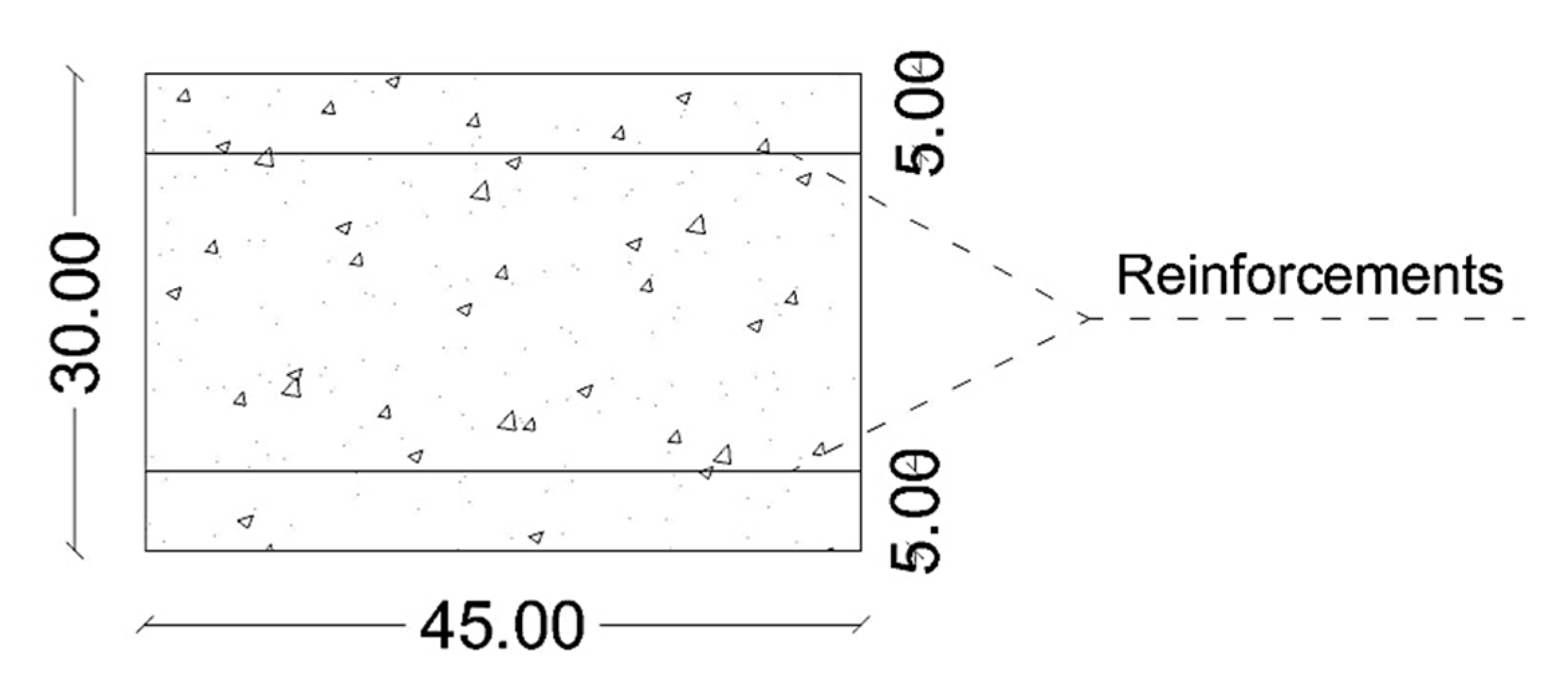
The proposed reinforcement strategy using zigzag-shaped steel and Nitinol wires was analytically evaluated under three-point bending tests in Abaqus. Four specimens were studied: an unreinforced sample (URS), a steel-reinforced sample (SRS), and two Nitinol-reinforced samples with distinct behaviors, superelasticity (SMARS-SE) and shape memory effect (SMARS-SME). The load was applied parallel to the printing layers, and reinforcements were placed between the printed layers (inter-layer reinforcement). The mechanical responses of each specimen are discussed below, with emphasis on cracking behavior, moment capacity, ductility, and failure mechanism. Figure 18 shows the moment-displacement diagram for the samples. It is important to note that throughout this study, deflection or displacement, whether referenced in the analysis or in the presented diagrams, specifically refers to the vertical displacement of the beam’s center point. This displacement was measured precisely at the reference point where the concentrated displacement load was applied.

5.1. Unreinforced Sample (URS)

The specimens were subjected to three-point bending tests, and the results were extracted from the analysis. Figure 19, Figure 20 and 
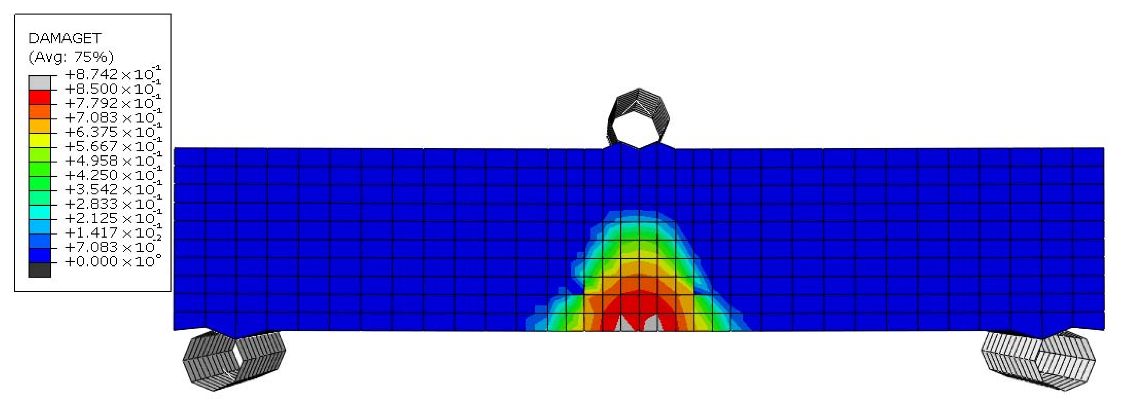
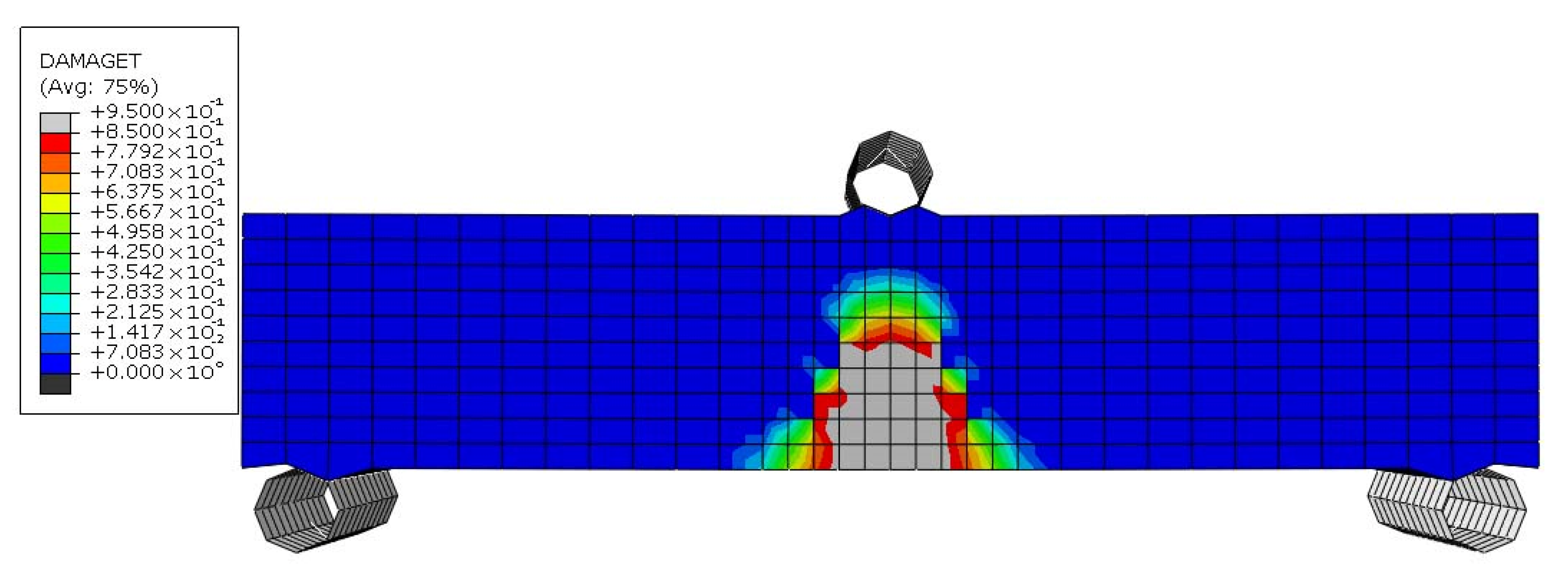
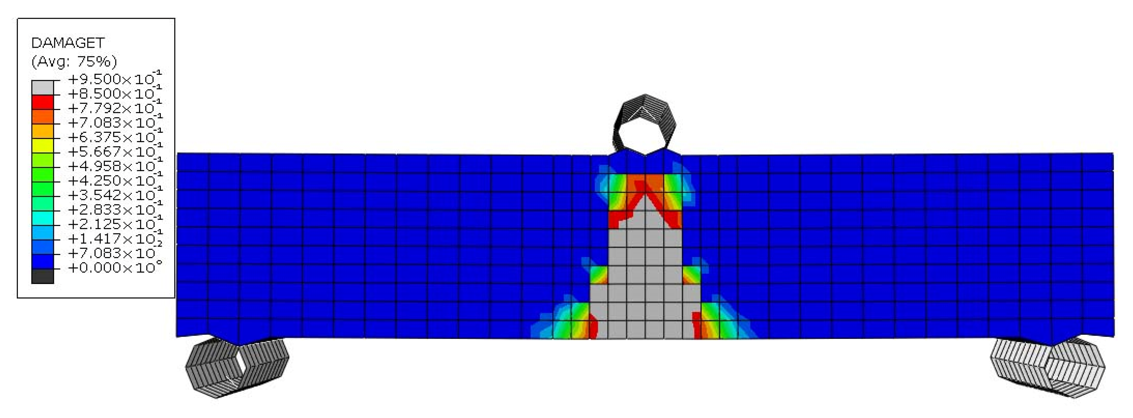
Figure 21 illustrate the failure mechanism of the URS sample. As observed in Figure 19, the URS specimen began cracking at a displacement of 0.04 mm, starting from the lowest level of the beam. With an increase in displacement load, the cracks propagated vertically, and their width increased. At a displacement of approximately 0.05 mm, more than half of the beam’s height had failed (Figure 20). Finally, at a displacement of 0.07 mm, the beam collapsed completely (Figure 21).
The URS sample exhibited a maximum moment resistance of 65.222 × 10³ N.mm at a midspan deflection of 0.038 mm. The URS sample showed classic brittle behavior due to the absence of reinforcement. Cracks initiated early under tensile stress, and no mechanism existed to bridge or delay their propagation. Concrete has very low tensile strength and no capacity for significant plastic deformation, leading to sudden and brittle collapse.

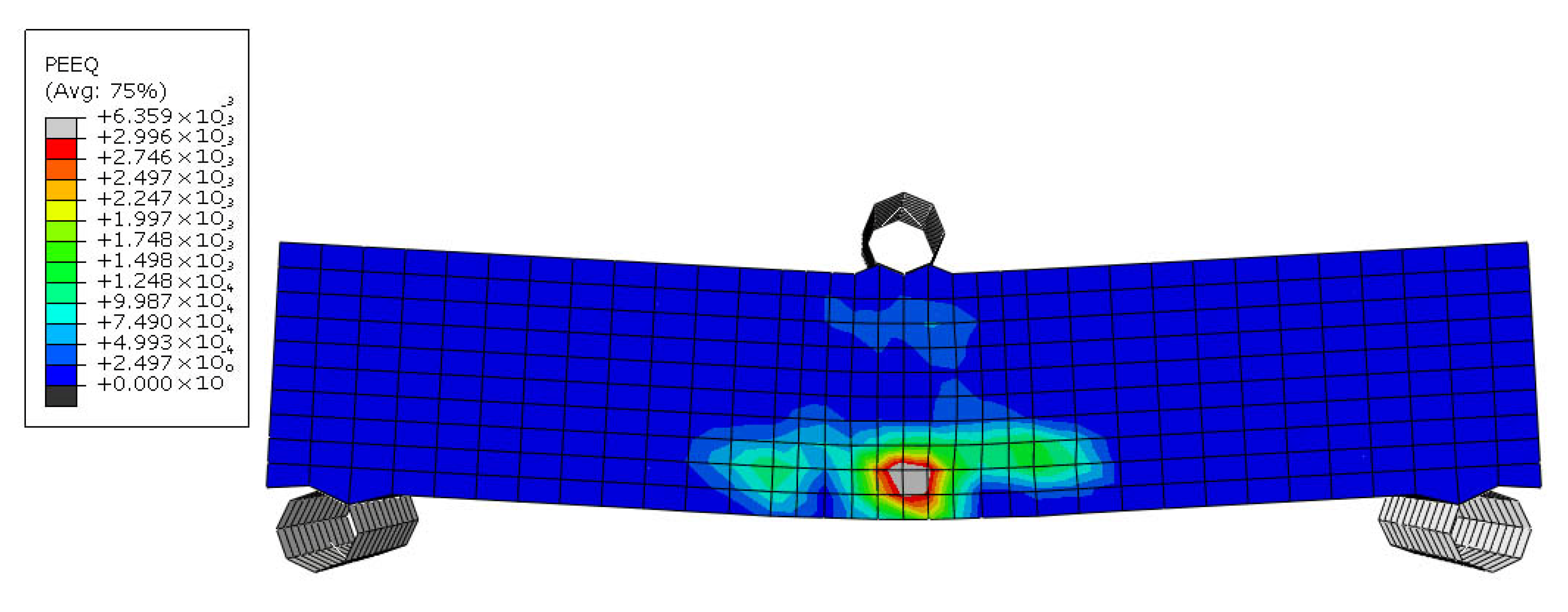
5.2. Steel Reinforced Sample (SRS)

Figure 22, Figure 23, Figure 24 and 
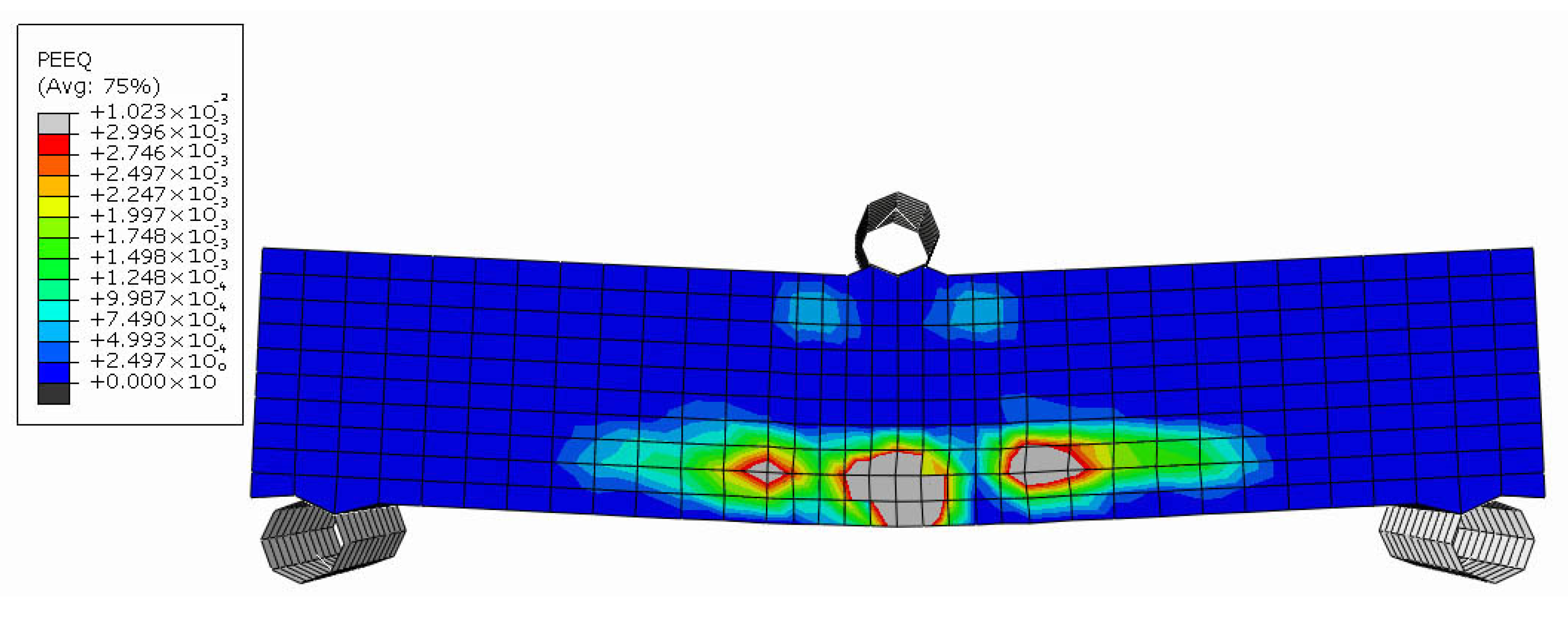
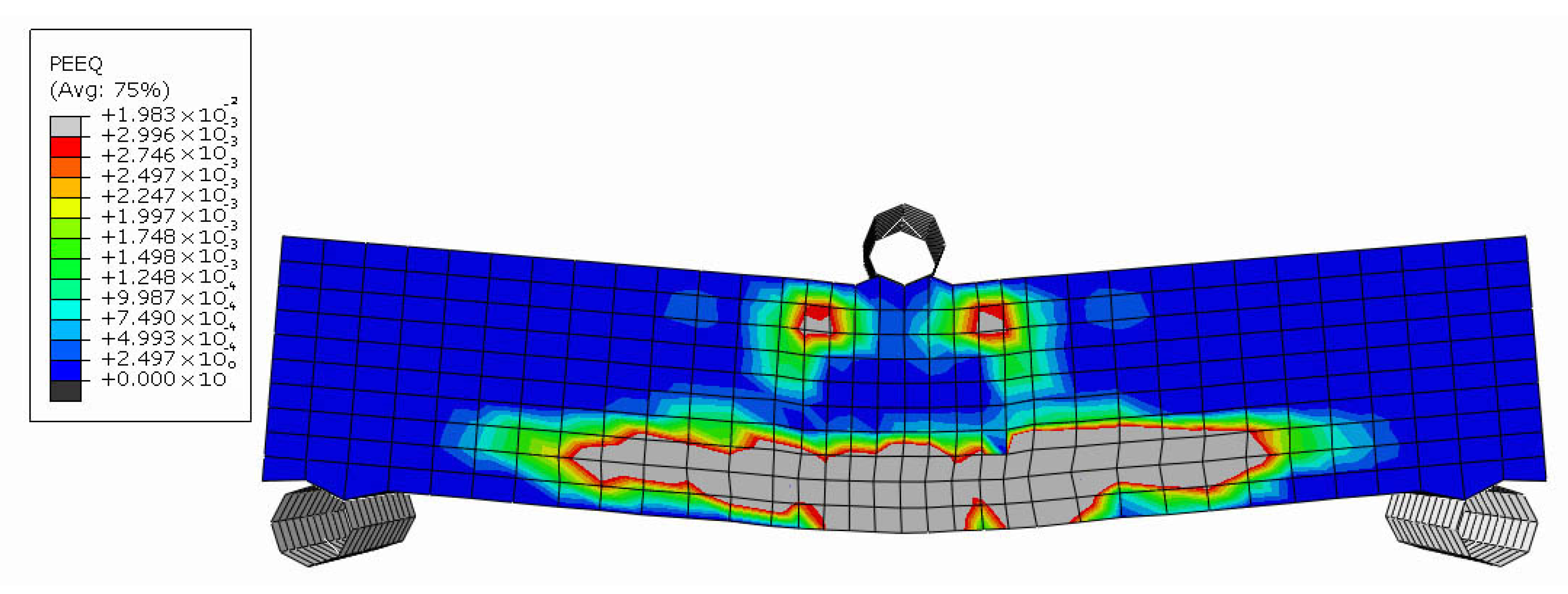
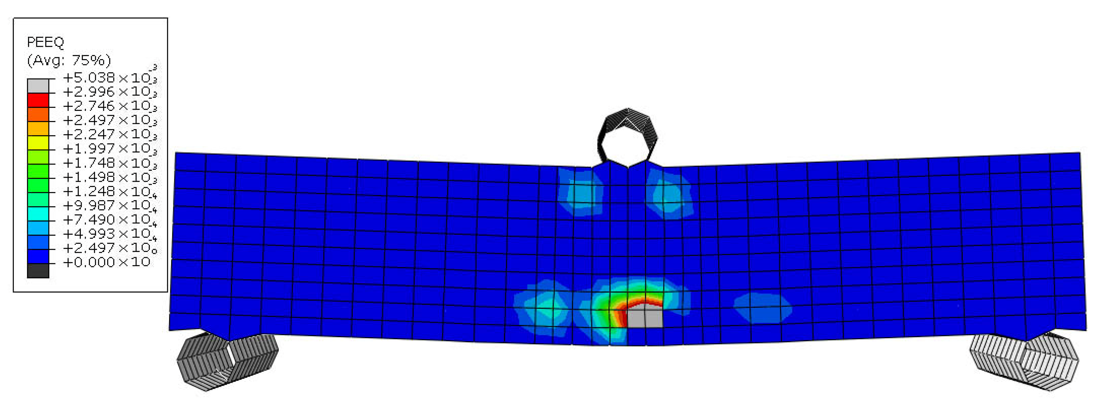
Figure 25 depict the failure mechanism of the SRS sample. In this specimen, the steel zigzag wires contributed to resisting the applied stresses and delayed the onset of cracking, with the first cracks occurring at a deflection of approximately 0.29 mm due to Figure 22. As the applied load increased, cracks propagated horizontally at the level of the bottom reinforcement. At this stage, the zigzag reinforcement effectively prevented the vertical growth of cracks (Figure 23).
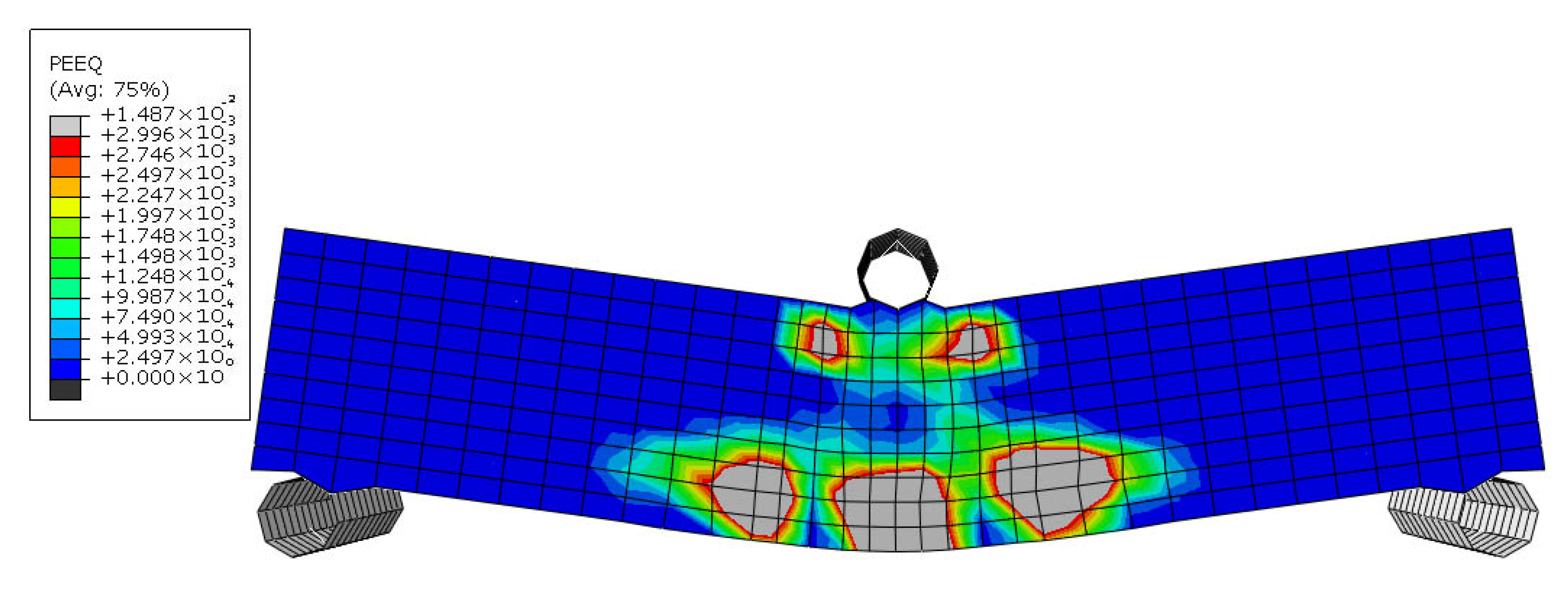
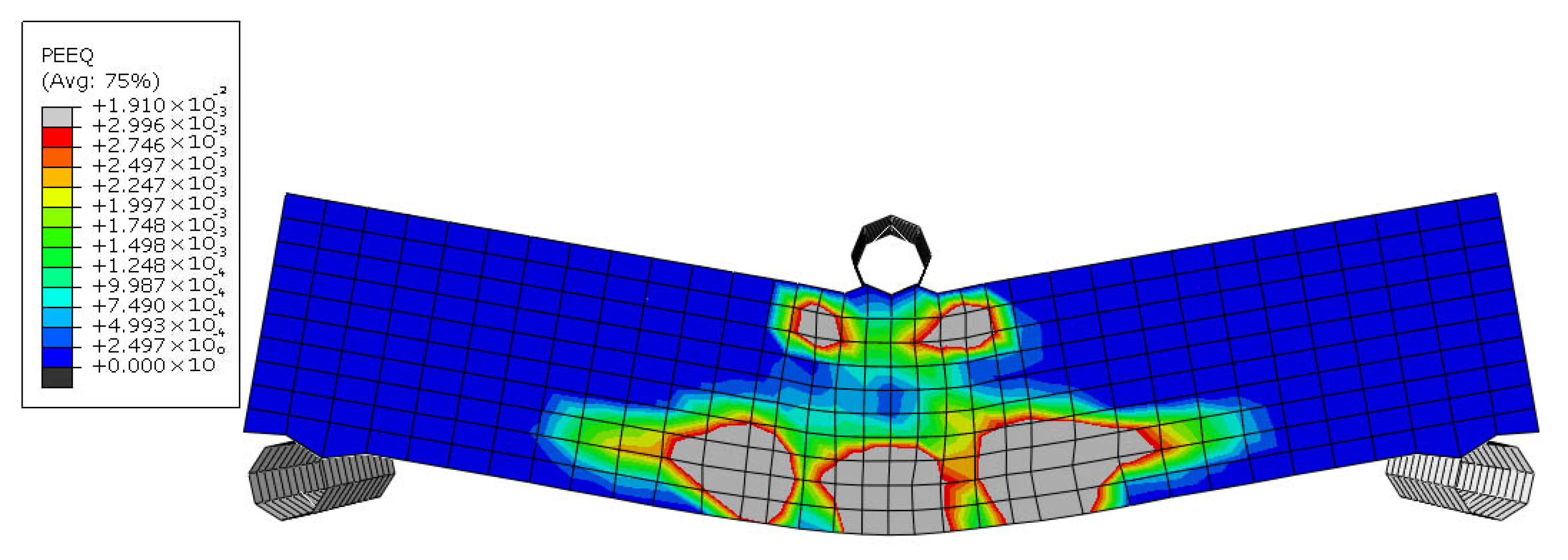
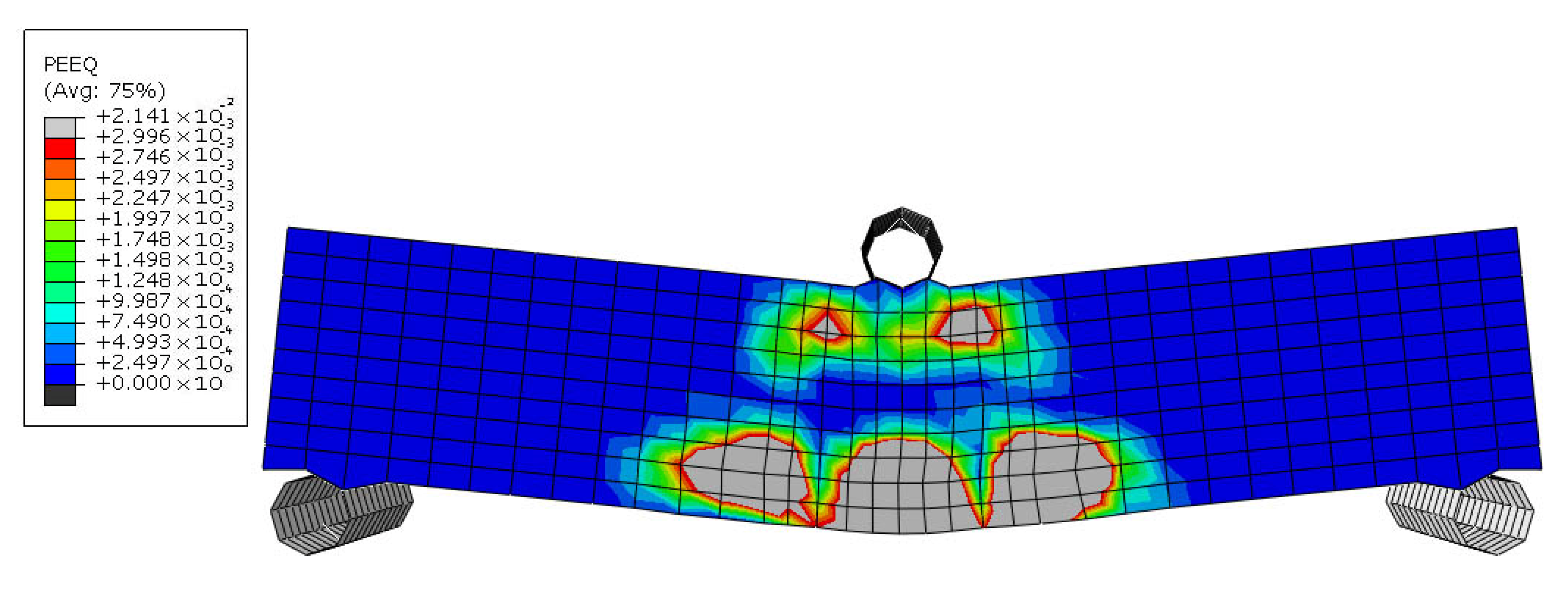
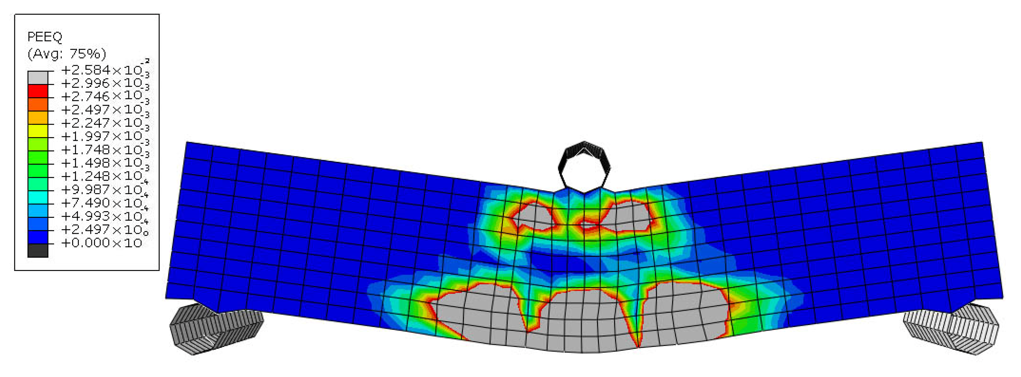
At a deflection of 1.15 mm, the tensile zone of the specimen’s section failed (Figure 24), causing the neutral axis to shift upward, above the bottom-level reinforcements. As the specimen approached its maximum moment capacity, at a deflection of approximately 2 mm (Figure 25), the maximum moment resistance recorded in flexure was 109.848 × 10³ N.mm. This represents a 68% increase in maximum moment resistance and a 286% improvement in flexibility compared to the URS sample, demonstrating a significant enhancement in structural performance.
Steel reinforcement provided excellent stress transfer due to its high modulus of elasticity (200 GPa). The zigzag geometry improved anchorage and distributed stress over a wider area. The delayed cracking and extended deflection to failure indicate significant energy absorption and plastic deformation after cracking. The high ratio of the maximum moment (109 × 103 N.mm) to the moment at which the first crack occurred (70.715 × 10³ N.mm), reflects the steel’s ability to carry increasing loads post-cracking, due to strain hardening and continuous stress redistribution.
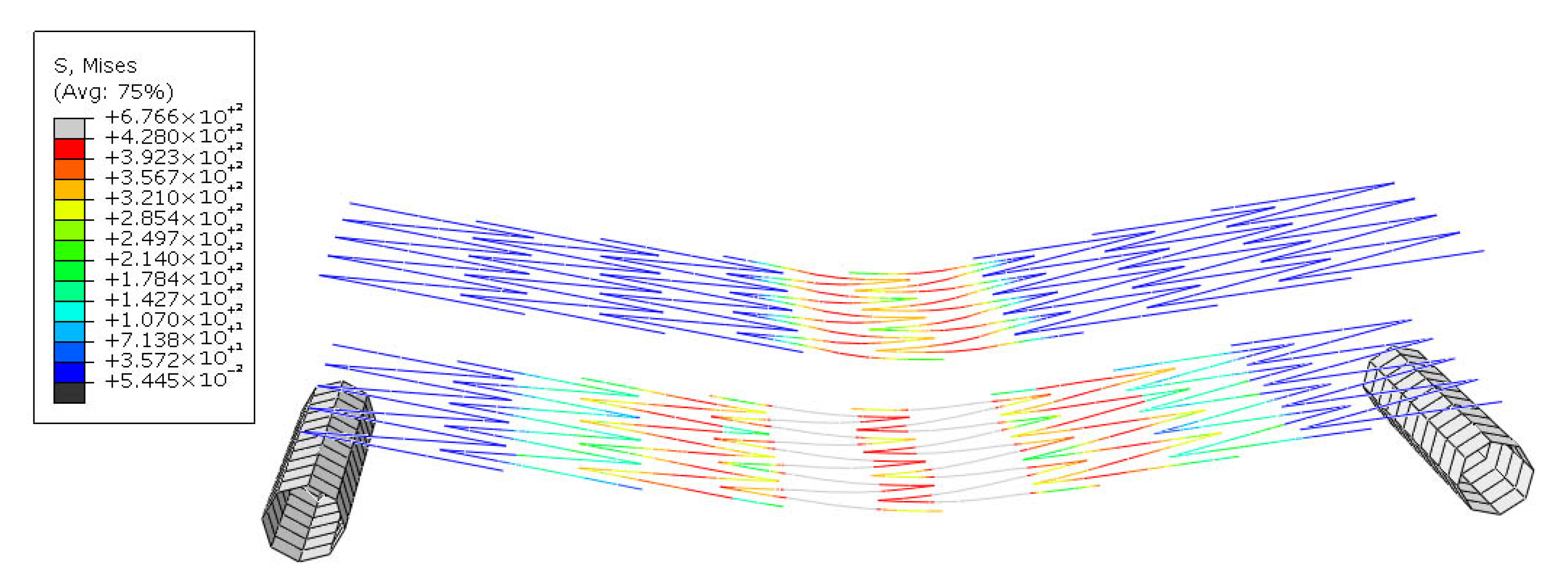
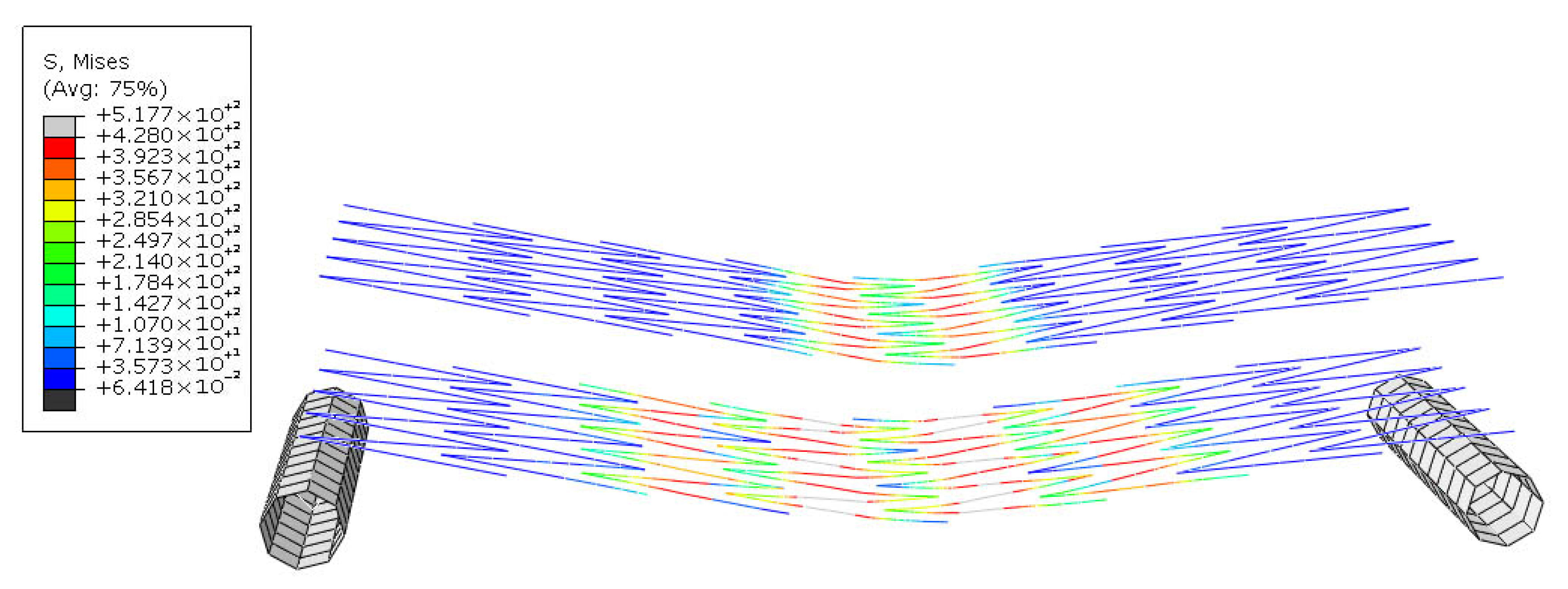
Figure 26 illustrates the distribution of Mises stress in the steel reinforcements of the SRS specimen at a deflection of 1.94 mm. At this displacement, the steel zigzag reinforcements reached their yield strength, marking the point at which the section collapses completely.

5.3. Shape Memory Alloy Reinforced Sample with Superelasticity Behavior (SMARS-SE)

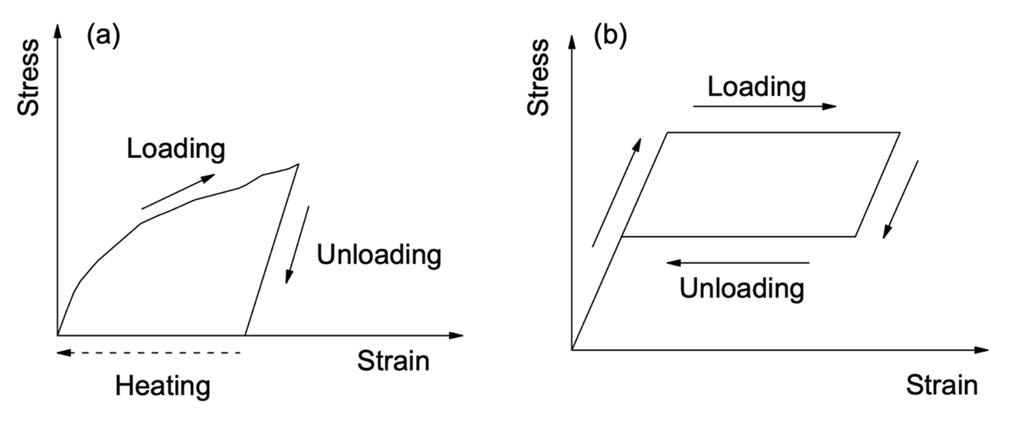
The SMARS-SE specimen represents the sample in which the superelastic behavior of Nitinol Shape Memory Alloy (SMA) was investigated as a zigzag-shaped reinforcement in 3DCP. As a brief review, superelasticity is a unique characteristic of SMAs, allowing the alloy to elastically deform up to approximately 6% of its initial length in the austenite phase (with Nitinol capable of deforming nearly 8%), whereas most conventional metals exhibit elastic deformation of less than 1% [59]. The SMARS-SE specimen exhibited initial cracking at a deflection of 0.81 mm, occurring in the interaction zone between the reinforcement material and concrete at the midspan, as shown in Figure 27. In comparison, the SRS specimen experienced its first crack at a deflection of 0.29 mm.
With the increase in applied load, the cracks propagated horizontally at the level of the embedded reinforcements, as shown in Figure 28. At a displacement of 2.1 mm, the section experienced cracking in the tension zone due to Figure 29, eventually leading to complete failure at a deflection of 2.67 mm, as illustrated in Figure 30. The SMARS-SE specimen exhibited a moment resistance of 67.680 × 10³ N.mm at a deflection of 2.68 mm.
Figure 31 shows the Nitinol reinforcements reaching their yield stress at the final point of the beam’s flexibility.
The superelastic behavior of Nitinol allows reversible deformation up to 8%, due to stress-induced martensitic transformation. This property delayed the onset of cracking by absorbing deformation energy without permanent strain. Despite high flexibility, the low elastic modulus (68.2 GPa) of Nitinol reduced its ability to resist high moments, explaining its lower maximum moment compared to steel. Nitinol’s function is more damping-oriented than strength-oriented; it efficiently dissipates energy via hysteresis but does not significantly stiffen the beam after cracking. The relatively lower λ compared to SRS indicates modest post-cracking strength improvement due to limited stress transfer across cracks.

5.4. Shape Memory Alloy Reinforced Sample with Shape Memory Effect Behavior (SMARS-SME)

The last specimen, SMARS-SME, was simulated to investigate the Shape Memory Effect (SME) behavior of Nitinol in the proposed reinforcing method. Initial cracks appeared at a deflection of 0.5 mm according to Figure 32. At 1.24 mm displacement, the tension zone in the midspan failed due to Figure 33. Simultaneously, cracks started forming in the compression zone. The beam completely collapsed when the displacement load reached 2 mm due to Figure 34. The ultimate moment resistance in flexure before failure was 102.508 × 10³ N.mm. Stress distribution in Nitinol reinforcements of the SMARS-SME sample is presented in Figure 35.
In this specimen, the recovery stress of the Nitinol zigzag reinforcements, which occurs due to thermal loading in practical cases (triggered by phase transformation temperature), was applied by defining a pre-defined field in the initial step of the simulation. This stress helped resist early cracking, which explains the highest cracking moment among all samples. However, the post-cracking moment gain was minimal, suggesting that the beam’s capacity to carry additional loads after the first crack was limited. This is due to the nature of the shape memory effect; once recovery stress is activated, additional loading does not lead to active resistance from the SMA. Instead, energy is primarily stored and released through phase transformation, not through added stiffness or plastic resistance.

5.5. Comparative Evaluation of Reinforced and Unreinforced Samples

In the presented stress and strain distribution diagrams, the Plastic Strain Equivalent parameter was used for reinforced samples due to their flexible failure mode and the interaction between reinforcements and concrete. For the unreinforced specimen, the DamageT (tension damage) parameter in Abaqus was used to capture its brittle failure behavior. It should be noted that all samples exhibited initial cracking at the lowest level of the section, similar to what is shown in Figure 19. However, in the reinforced samples, the cover below the bottom reinforcements was not considered in the analysis because it is entirely in the tension zone and does not contribute to load-bearing in tension.
Table 10 shows a summary of the results obtained from analysis.
μ = δ m a x δ c r a c k
A higher μ means the beam exhibits better ductility and post-cracking performance.
λ is the ratio of ultimate load to load at first cracking and can be calculated from Equation (3): Rate of ultimate load to the load at the first crack.
λ = M m a x M c r a c k
A higher λ signifies that a structure can deform significantly after the first crack appears, allowing for more energy absorption before failure.
Due to Table 10, SRS exhibited the highest ductility (μ = 6.9), followed by the Nitinol-reinforced samples with shape memory effect (SMARS-SME, μ = 4.00) and superelasticity behavior (SMARS-SE, μ = 3.30). The unreinforced sample (URS) showed the lowest ductility (demonstrating brittle failure behavior). Among the reinforced samples, the steel-reinforced beam (SRS) demonstrated the highest λ value of 1.55, signifying that it could withstand a substantial increase in load after the first crack. This behavior is expected, as steel reinforcement effectively bridges cracks and redistributes stresses, preventing sudden failure. The superelastic Nitinol-reinforced sample (SMARS-SE) exhibited a lower λ of 1.35, suggesting that while it provides some load-bearing capacity beyond cracking, its post-cracking strength enhancement is not as significant as steel. This can be attributed to Nitinol’s superelastic behavior, which allows it to recover strains but does not contribute significantly to post-cracking stiffness. The shape memory effect Nitinol-reinforced beam (SMARS-SME) had the lowest λ value of 1.04, indicating that after the first crack, it could sustain only a marginal increase in load before failure. This suggests that while the pre-stressed Nitinol reinforcement in SMARS-SME helped delay cracking (as evidenced by its high cracking moment Mcrack = 98.625 × 10³ N.mm [60]), it did not significantly enhance the beam’s ability to carry additional load beyond that point. This behavior is likely due to the nature of shape memory alloys (SMAs), where most of the energy is stored and released through phase transformation rather than direct strengthening of the cracked section.
Overall, the results indicate that while both Nitinol-reinforced samples provide advantages in terms of crack resistance and energy dissipation, their ability to sustain additional load post-cracking is lower than that of steel-reinforced concrete. The SRS beam remains the most effective in terms of post-cracking load-bearing capacity, making it the preferred choice for applications where maintaining strength beyond initial cracking is critical. However, the use of Nitinol, particularly in its superelastic form, may be beneficial in structures where self-healing or recovery properties are prioritized over post-cracking strength.

6. Conclusions

This study introduces and evaluates a zigzag-shaped in-process reinforcement strategy for Three-Dimensional Concrete Printing (3DCP), using both conventional steel and Nitinol Shape Memory Alloys (SMA) to address one of the key limitations in additive construction: the lack of efficient reinforcement integration during printing. Using nonlinear finite-element modeling, four beam configurations—unreinforced (URS), steel-reinforced (SRS), and two SMA-reinforced beams exhibiting superelastic (SMARS-SE) and shape memory effect (SMARS-SME) behavior—were assessed under three-point bending. The following conclusions are drawn:
  • The zigzag-shaped reinforcement improved mechanical interlock and post-cracking performance by bridging printed layers and delaying crack propagation. In particular, SRS specimens exhibited the highest flexural strength and ductility, validating the effectiveness of the proposed geometry in enhancing performance in 3D printed structures.
  • SMA-reinforced samples displayed distinctive advantages: SMARS-SE delayed crack initiation by nearly 200% compared to steel, while SMARS-SME exhibited the highest cracking moment, benefiting from prestressing effects. However, both showed reduced post-cracking load-bearing capacity compared to steel, due to limited stiffness recovery and non-activated SMA behavior in the simulation.
  • Ductility indices confirmed that while steel remains superior in overall deformation capacity, SMA reinforcements, especially in zigzag configurations, can improve energy dissipation and early-stage structural performance in printed elements.
  • Despite promising structural responses, the SMA-concrete bond behavior under cyclic, thermal, or long-term loading remains uncertain and was not fully captured in this simulation-based study.
This work establishes the potential of smart and non-linear reinforcement geometries, such as the proposed zigzag configuration, to improve the mechanical reliability of 3D printed concrete while remaining compatible with the layer-by-layer printing process. While traditional steel reinforcement still outperforms in strength and ductility, SMA offers functional advantages such as crack control, energy dissipation, and potential self-healing, making it promising for future intelligent infrastructure.
Further work is needed to experimentally validate the simulation results, especially focusing on:
  • the mechanical behavior of SMA-concrete interfaces under environmental and seismic loading.
  • thermal activation and recovery capabilities of SMA in printed elements.
  • optimization of insertion techniques for full automation in 3DCP.
  • comparative studies involving other reinforcement types and geometries.
Scaling the concept from small beams to complex structural forms, including curved or multiaxial elements, and integrating real-time activation or monitoring systems will further define the practical boundaries of this approach. Hardware development to embed reinforcements during deposition, such as robotic guides or integrated feeders, will also be crucial in transforming this method into a viable industrial process.

Author Contributions

Conceptualization, B.A.; methodology, B.A.; software, B.A.; validation, B.A. and M.V.L.; formal analysis, B.A.; investigation, B.A.; resources, B.A.; data curation, B.A.; writing—original draft preparation, B.A.; writing—review and editing, B.A. and M.V.L.; visualization, B.A.; supervision, M.V.L.; project administration, B.A.; funding acquisition, B.A. All authors have read and agreed to the published version of the manuscript.

Funding

This research received no external funding.

Data Availability Statement

The data presented in this study are available on request from the corresponding author due to the ongoing investigation project.

Conflicts of Interest

The authors declare no conflict of interest.

Abbreviation and Symbols

3DThree Dimensional
3DCPThree-Dimensional Concrete Printing
3DP-SHAAC3D-printable strain-hardening alkali-activated composite
ΨDilation Angle
δ ε v shear strain
δ v volumetric strain
δDeflection
μductility index
λthe ratio of ultimate load to load at first cracking
AR-glassAlkali-resistance glass
CAEComputer Aided Engineering
FEFinite-Element
fb0biaxial compressive strength
fc0uniaxial compressive strength
Hrheight of the reinforcement material
Hlheight of a single printing layer
Httotal height of printed layers
Kthe ratio of the second stress invariant on the tensile meridian
kgKilogram
Lolength of the overlap of reinforcement between sequent layers
Llength of the printed layers
MpaMega Pascal
MMoment
mmMillimeter
NNewton
NiNickel
Ni-TiNickel-Titanium
PApplied load to the samples
PVAPolyvinyl Alcohol
SMAShape Memory Alloy
SRSSteel-Reinforced Sample
SMARS-SEShape Memory Alloy Reinforced Sample—Superelasticity
SESuperelasticity
SMEShape Memory Effect
SMARS-SMEShape Memory Alloy Reinforced Sample—Shape Memory Effect
TiTitanium
UHPCUltra-High Performance Concrete
URSUnreinforced Sample
Wrwidth of a single step in the zigzag reinforcement
Wlwidth of a single printing layer

References

  1. Divyah, N.; Prakash, R.; Srividhya, S.; Avudaiappan, S.; Guindos, P.; Carsalade, N.M.; Arunachalam, K.P.; Noroozinejad Farsangi, E.; Roco-Videla, Á. Experimental and Numerical Investigations of Laced Built-Up Lightweight Concrete Encased Columns Subjected to Cyclic Axial Load. Buildings 2023, 13, 1444. [Google Scholar] [CrossRef]
  2. Prakash, R.; Thenmozhi, R.; Raman, S.N.; Subramanian, C. Characterization of eco-friendly steel fiber-reinforced concrete containing waste coconut shell as coarse aggregates and fly ash as partial cement replacement. Struct. Concr. 2020, 21, 437–447. [Google Scholar] [CrossRef]
  3. Abioye, S.O.; Oyedele, L.O.; Akanbi, L.; Ajayi, A.; Delgado, J.M.; Bilal, M.; Akinade, O.O.; Ahmed, A. Artificial intelligence in the construction industry: A review of present status, opportunities and future challenges. J. Build. Eng. 2021, 44, 103299. [Google Scholar] [CrossRef]
  4. Ahadi, B.; López, M.V. Development of demand divesrion model from conventional construction methods to 3D concrete printing (3DCP). In Proceedings of the International Technology, Education and Development, Valencia, Spain, 6–8 March 2023. [Google Scholar]
  5. Kloft, H.; Empelmann, M.; Hack, N.; Herrmann, E.; Lowke, D. Reinforcement strategies for 3D-concrete-printing. Civ. Eng. Des. 2020, 2, 131–139. [Google Scholar] [CrossRef]
  6. Ahadi, B.; López, M.V. Use of Nitinol-Shape Memory Alloy in the Reinforcement of 3D Concrete Printing Industry. In Proceedings of the 15th annual International Conference of Education, Research and Innovation (ICERI2022), Sevilla, Spain, 7–9 November 2022; IATED Digital Library: Valencia, Spain, 2022; pp. 7470–7479. [Google Scholar]
  7. Cai, J.; Sheng, Z.; Wang, X.; Fang, Y.; Pan, J. Effect of reinforcement configurations on the flexural behaviors of 3D printed fiber reinforced cementitious composite (FRCC) beams. J. Build. Eng. 2021, 46, 103773. [Google Scholar] [CrossRef]
  8. Souza, M.T.; Ferreira, I.M.; de Moraes, E.G.; Senff, L.; Novaes de Oliveira, A.P. 3D printed concrete for large-scale buildings: An overview of rheology, printing parameters, chemical admixtures, reinforcements, and economic and environmental prospects. J. Build. Eng. 2020, 32, 101833. [Google Scholar] [CrossRef]
  9. Sakin, M.; Kiroglu, Y.C. 3D Printing of Buildings: Construction of the Sustainable Houses of the Future by BIM. Sustain. Energy Build. 2017, 134, 702–711. [Google Scholar] [CrossRef]
  10. Buswell, R.A.; Leal de Silva, W.R.; Jones, S.Z.; Dirrenberger, J. 3D printing using concrete extrusion: A roadmap for research. Cem. Concr. Res. 2018, 112, 37–49. [Google Scholar] [CrossRef]
  11. Dai, S.; Zhu, H.; Zhai, M.; Wu, Q.; Yin, Z.; Qian, H.; Hua, S. Stability of steel slag as fine aggregate and its application in 3D printing materials. Constr. Build. Mater. 2021, 299, 123938. [Google Scholar] [CrossRef]
  12. Ahadi, B. Reinforcement of 3D Concrete Printing (3DCP) with Shape Memory Alloys; Universidad Politécnica de Madrid: Madrid, Spain, 2022. [Google Scholar]
  13. Ma, G.; Salman, N.M.; Wang, L.; Wang, F. A novel additive mortar leveraging internal curing for enhancing interlayer bonding of cementitious composite for 3D printing. Constr. Build. Mater. 2020, 244, 118305. [Google Scholar] [CrossRef]
  14. Wang, L.; Tian, Z.; Ma, G.; Zhang, M. Interlayer bonding improvement of 3D printed concrete with polymer modified mortar: Experiments and molecular dynamics studies. Cem. Concr. Compos. 2020, 110, 103571. [Google Scholar] [CrossRef]
  15. Ahadi, B.; Valiente, M. A new method for reinforce and design of 3D concrete printing (3DCP): Considering structural frames. In Proceedings of the 4th Building and Management International Conference, Madrid, Spain, 16–18 November 2022. [Google Scholar]
  16. Shahzad, Q.; Shen, J.; Naseem, R.; Yao, Y.; Waqar, S.; Liu, W. Influence of phase change material on concrete behavior for construction 3D printing. Constr. Build. Mater. 2021, 309, 125121. [Google Scholar] [CrossRef]
  17. Valente, M.; Sibai, A.; Sambucci, M. Extrusion-Based Additive Manufacturing of Concrete Products: Revolutionizing and Remodeling the Construction Industry. J. Compos. Sci. 2019, 3, 88. [Google Scholar] [CrossRef]
  18. Roussel, N. Rheological requirements for printable concretes. Cem. Concr. Res. 2018, 112, 76–85. [Google Scholar] [CrossRef]
  19. Kristombu Baduge, S.; Navaratnam, S.; Abu-Zidan, Y.; McCormack, T.; Nguyen, K.; Mendis, P.; Zhang, G.; Aye, L. Improving performance of additive manufactured (3D printed) concrete: A review on material mix design, processing, interlayer bonding, and reinforcing methods. Structures. Structures 2021, 29, 1597–1609. [Google Scholar] [CrossRef]
  20. Bechthold, M.; Weaver, J. Materials science and architecture. Nat. Rev. Mater. 2017, 2, 17082. [Google Scholar] [CrossRef]
  21. Afroughsabet, V.; Biolzi, L.; Ozbakkaloglu, T. High-performance fiber-reinforced concrete: A review. J. Mater. Sci. 2016, 51, 6517–6551. [Google Scholar] [CrossRef]
  22. Figura, L.O.; Teixeira, A.A. (Eds.) Rheological Properties. In Food Physics: Physical Properties—Measurement and Applications; Springer: Berlin/Heidelberg, Germany, 2007; pp. 117–206. [Google Scholar]
  23. BFT International. Chemical Admixtures For 3D Printing of Concrete. 2022. Available online: https://www.bft-international.com/en/artikel/bft_Chemical_Admixtures_For_3D_Printing_of_Concrete-3772184.html (accessed on 10 June 2022).
  24. Sukontasukkul, P.; Panklum, K.; Maho, B.; Banthia, N.; Jongvivatsakul, P.; Imjai, T.; Sata, V.; Limkatanyu, S.; Chindaprasirt, P. Effect of synthetic microfiber and viscosity modifier agent on layer deformation, viscosity, and open time of cement mortar for 3D printing application. Constr. Build. Mater. 2022, 319, 126111. [Google Scholar] [CrossRef]
  25. Chen, Y.; Chaves Figueiredo, S.; Yalçinkaya, Ç.; Çopuroğlu, O.; Veer, F.; Schlangen, E. The Effect of Viscosity-Modifying Admixture on the Extrudability of Limestone and Calcined Clay-Based Cementitious Material for Extrusion-Based 3D Concrete Printing. Materials 2019, 12, 1374. [Google Scholar] [CrossRef] [PubMed]
  26. Ramezani, A.; Modaresi, S.; Dashti, P.; GivKashi, M.R.; Moodi, F.; Ramezanianpour, A.A. Effects of Different Types of Fibers on Fresh and Hardened Properties of Cement and Geopolymer-Based 3D Printed Mixtures: A Review. Buildings 2023, 13, 945. [Google Scholar] [CrossRef]
  27. Sikora, P.; Chougan, M.; Cuevas, K.; Liebscher, M.; Mechtcherine, V.; Ghaffar, S.H.; Liard, M.; Lootens, D.; Krivenko, P.; Sanytsky, M.; et al. The effects of nano- and micro-sized additives on 3D printable cementitious and alkali-activated composites: A review. Appl. Nanosci. 2021, 12, 805–823. [Google Scholar] [CrossRef]
  28. Kaushik, S.; Sonebi, M.; Amato, G.; Perrot, A.; Das, U.K. Influence of nanoclay on the fresh and rheological behaviour of 3D printing mortar. Mater. Today Proc. 2022, 58, 1063–1068. [Google Scholar] [CrossRef]
  29. Dvorkin, L.; Konkol, J.; Marchuk, V.; Huts, A. Effectiveness of Polymer Additives in Concrete for 3D Concrete Printing Using Fly Ash. Polymers 2022, 14, 5467. [Google Scholar] [CrossRef]
  30. Chen, Y.; Zhang, Y.; Zhang, Y.; Pang, B.; Zhang, W.; Liu, C.; Liu, Z.; Wang, D.; Sun, G. Influence of gradation on extrusion-based 3D printing concrete with coarse aggregate. Constr. Build. Mater. 2023, 403, 133135. [Google Scholar] [CrossRef]
  31. Wang, H.; Belarbi, A. Ductility characteristics of fiber-reinforced-concrete beams reinforced with FRP rebars. Constr. Build. Mater. 2011, 25, 2391–2401. [Google Scholar] [CrossRef]
  32. Ahadi, B.; López, M.V. Development of an In-Process Reinforcement Method in 3D Concrete Printing with Nitinol Shape Memory Alloy. In Proceedings of the 8th International Conference on Technological Innovation in Building (CITE 2023), Madrid, Spain, 22–24 March 2023. [Google Scholar]
  33. Ahmed, G.H.; Askandar, N.H.; Jumaa, G.B. A review of largescale 3DCP: Material characteristics, mix design, printing process, and reinforcement strategies. Structures 2022, 43, 508–532. [Google Scholar] [CrossRef]
  34. Van Der Putten, J.; De Schutter, G.; Van Tittelboom, K. (Eds.) The Effect of Print Parameters on the (Micro)structure of 3D Printed Cementitious Materials. In First RILEM International Conference on Concrete and Digital Fabrication—Digital Concrete 2018; Springer International Publishing: Cham, Switzerland, 2019. [Google Scholar]
  35. Lim, S.; Buswell, R.A.; Le, T.T.; Austin, S.A.; Gibb, A.G.F.; Thorpe, T. Developments in construction-scale additive manufacturing processes. Autom. Constr. 2012, 21, 262–268. [Google Scholar] [CrossRef]
  36. Wang, L.; Ma, G.; Liu, T.; Buswell, R.; Li, Z. Interlayer reinforcement of 3D printed concrete by the in-process deposition of U-nails. Cem. Concr. Res. 2021, 148, 106535. [Google Scholar] [CrossRef]
  37. Marchment, T.; Sanjayan, J. Reinforcement method for 3D concrete printing using paste-coated bar penetrations. Autom. Constr. 2021, 127, 103694. [Google Scholar] [CrossRef]
  38. Marchment, T.; Sanjayan, J. Mesh reinforcing method for 3D Concrete Printing. Autom. Constr. 2020, 109, 102992. [Google Scholar] [CrossRef]
  39. Hambach, M.; Volkmer, D. Properties of 3D-printed fiber-reinforced Portland cement paste. Cem. Concr. Compos. 2017, 79, 62–70. [Google Scholar] [CrossRef]
  40. Hojati, M.; Memari, A.M.; Zahabi, M.; Wu, Z.; Li, Z.; Park, K.; Nazarian, S.; Duarte, J.P. Barbed-wire reinforcement for 3D concrete printing. Autom. Constr. 2022, 141, 104438. [Google Scholar] [CrossRef]
  41. Ahadi, B.; López, M.V. Use of Nitinol Fibers In the Reinforcement of 3D Concrete Printing. In Proceedings of the 5th Building and Management International Conference, Madrid, Spain, 21–23 November 2023. [Google Scholar]
  42. Gebhard, L.; Mata-Falcón, J.; Anton, A.; Burger, J.; Lloret-Fritschi, E.; Reiter, L.; Dillenburger, B.; Gramazio, F.; Kohler, M.; Flatt, R.; et al. (Eds.) Aligned Interlayer Fibre Reinforcement and Post-tensioning as a Reinforcement Strategy for Digital Fabrication. In Second RILEM International Conference on Concrete and Digital Fabrication 2020; Springer International Publishing: Cham, Switzerland, 2020. [Google Scholar]
  43. Arunothayan, A.R.; Nematollahi, B.; Ranade, R.; Bong, S.H.; Sanjayan, J.G.; Khayat, K.H. Fiber orientation effects on ultra-high performance concrete formed by 3D printing. Cem. Concr. Res. 2021, 143, 106384. [Google Scholar] [CrossRef]
  44. Ramesh, A.; Rajeev, P.; Sanjayan, J.; Mechtcherine, V. In-process textile reinforcement method for 3D concrete printing and its structural performance. Eng. Struct. 2024, 314, 118337. [Google Scholar] [CrossRef]
  45. Ramesh, A.; Rajeev, P.; Xu, S.; Sanjayan, J.; Lu, G. Impact response of textile-reinforced 3D printed concrete panels. Eng. Struct. 2024, 315, 118489. [Google Scholar] [CrossRef]
  46. Bong, S.H.; Nematollahi, B.; Nerella, V.N.; Mechtcherine, V. Method of formulating 3D-printable strain-hardening alkali-activated composites for additive construction. Cem. Concr. Compos. 2022, 134, 104780. [Google Scholar] [CrossRef]
  47. Marchment, T.; Sanjayan, J.G.; Nematollahi, B.; Xia, M. Chapter 12—Interlayer Strength of 3D Printed Concrete: Influencing Factors and Method of Enhancing. In 3D Concrete Printing Technology; Sanjayan, J.G., Nazari, A., Nematollahi, B., Eds.; Butterworth-Heinemann: Oxford, UK, 2019; pp. 241–264. [Google Scholar]
  48. Training Group. Concrete Damage Plasticity (CDP) in Abaqus. Available online: https://caeassistant.com/blog/concrete-damage-plasticity-cdp-abaqus-video/#:~:text=Studies%20indicate%20that%20for%20reinforced%20concrete%2C%20the,behavior%20in%20both%20compression%20and%20tension%20scenarios (accessed on 19 April 2025).
  49. Ghoraba, A. The Strut-and-Tie Method Versus Nonlinear Finite Element Analysis. 2017. Available online: https://www.researchgate.net/publication/342378141_The_Strut-andTie_Method_Versus_Nonlinear_Finite_Element_Analysis (accessed on 20 December 2024).
  50. Ferreira, M.; Ribeiro, M.; Marques, A. Analysis of hybrid beams of polymer concrete and composite materials. Int. J. Mech. Mater. Des. 2004, 1, 143–155. [Google Scholar] [CrossRef]
  51. Khatibinia, M.; Chiti, H.; Akbarpour, A.; Naseri, H. Shape optimization of concrete gravity dams considering dam–water–foundation interaction and nonlinear effects. Int. J. Optim. Civ. Eng. 2016, 6, 115–134. [Google Scholar]
  52. Simulia, D. Available online: https://classes.engineering.wustl.edu/2009/spring/mase5513/abaqus/docs/v6.6/books/key/default.htm?startat=ch04abk29.html (accessed on 19 April 2025).
  53. Turteltaub, S. Inelastic Analysis of Structures; Jirásek, M., Bažant, Z.P., Eds.; John Wiley & Sons: Hoboken, NJ, USA, 2002; p. 758. ISBN 0-471-98716-6. [Google Scholar]
  54. Grassl, P.; Jirásek, M. Damage-plastic model for concrete failure. Int. J. Solids Struct. 2006, 43, 7166–7196. [Google Scholar] [CrossRef]
  55. Manual, A.T. Damaged Plasticity Model for Concrete and Other Quasi-Brittle Materials. Available online: https://classes.engineering.wustl.edu/2009/spring/mase5513/abaqus/docs/v6.6/books/stm/default.htm?startat=ch04s05ath120.html (accessed on 15 January 2025).
  56. Concilio, A.; Antonucci, V.; Auricchio, F.; Lecce, L.; Sacco, E. (Eds.) Section 1—Introduction. In Shape Memory Alloy Engineering, 2nd ed.; Butterworth-Heinemann: Boston, MA, USA, 2021; p. 1. [Google Scholar]
  57. Tsuchiya, K. 1—Mechanisms and properties of shape memory effect and superelasticity in alloys and other materials: A practical guide. In Shape Memory and Superelastic Alloys; Yamauchi, K., Ohkata, I., Tsuchiya, K., Miyazaki, S., Eds.; Woodhead Publishing: Sawston, UK, 2011; pp. 3–14. [Google Scholar]
  58. Bykiv, N.; Yasniy, P.; Lapusta, Y.; Iasnii, V. Finite element analysis of reinforced-concrete beam with shape memory alloy under the bending. Procedia Struct. Integr. 2022, 36, 386–393. [Google Scholar] [CrossRef]
  59. Concilio, A.; Antonucci, V.; Auricchio, F.; Lecce, L.; Sacco, E. (Eds.) Section 7—Civil. In Shape Memory Alloy Engineering, 2nd ed.; Butterworth-Heinemann: Boston, MA, USA, 2021; p. 687. [Google Scholar]
  60. Alam, M.S.; Youssef, M.A.; Nehdi, M. Analytical prediction of the seismic behaviour of superelastic shape memory alloy reinforced concrete elements. Eng. Struct. 2008, 30, 3399–3411. [Google Scholar] [CrossRef]
Figure 1. Growth of additive manufacturing in construction applications since 1996 (Buswell et al. [10]).
Buildings 15 01721 g001
Figure 2. Mesh insertion and the custom-designed 3DCP nozzle (Marchment et al. [38]).
Buildings 15 01721 g002
Figure 3. (a) Shape and dimension of U-nails (b) printed sample with embedded U-nails (Wang et al. [36]).
Buildings 15 01721 g003
Figure 4. In-process fiber reinforcement in 3DCP; (a) fiber placer, (b) extruder nozzle, (c) printing direction (Gebhard et al. [42]).
Buildings 15 01721 g004
Figure 5. Use of textile reinforcement in 3DCP (Ramesh et al. [44]).
Buildings 15 01721 g005
Figure 6. Use of barbed-wires in the study of Hojati et al. [40].
Buildings 15 01721 g006
Figure 7. Shape of a single zigzag wire, schematically (authors).
Buildings 15 01721 g007
Figure 8. Schematically embedded zigzag wires in printed layers, (a) section view, (b) side view (authors).
Buildings 15 01721 g008
Figure 9. Longitudinal continuous reinforcement (authors).
Buildings 15 01721 g009
Figure 10. Internal view of reinforced layers, overlap and interlayer focus (authors).
Buildings 15 01721 g010
Figure 11. Section view of a printing layer (authors).
Buildings 15 01721 g011
Figure 12. Considered length of the layers (authors).
Buildings 15 01721 g012
Figure 13. Sample geometric properties (a) section view (b) side view (authors).
Buildings 15 01721 g013
Figure 14. Simulated concrete sample in Abaqus area (authors).
Buildings 15 01721 g014
Figure 15. Stress-Strain curves (a) Shape memory effect and (b) Superelasticity (Tsuchiya [57]).
Buildings 15 01721 g015
Figure 16. Embedded reinforcements in the concrete element in Abaqus area, ×RP is the reference point where the load was applied, (authors).
Buildings 15 01721 g016
Figure 17. Section of the reinforced samples (authors).
Buildings 15 01721 g017
Figure 18. Moment-displacement diagram of analyzed specimens (authors).
Buildings 15 01721 g018
Figure 19. Initial cracks in URS sample (authors).
Buildings 15 01721 g019
Figure 20. Failure of tension zone of the section in URS sample (authors).
Buildings 15 01721 g020
Figure 21. Complete failure of URS sample (authors).
Buildings 15 01721 g021
Figure 22. Initial cracks in SRS specimen (authors).
Buildings 15 01721 g022
Figure 23. Propagation of the cracks in tension zone of the SRS specimen (authors).
Buildings 15 01721 g023
Figure 24. Failure of the SRS sample in the tension zone (authors).
Buildings 15 01721 g024
Figure 25. Complete failure of the SRS sample (authors).
Buildings 15 01721 g025
Figure 26. Distribution of Mises stress in the reinforcements of SRS specimen (authors).
Buildings 15 01721 g026
Figure 27. Initial cracks in SMARS-SE specimen (authors).
Buildings 15 01721 g027
Figure 28. Propagation of cracks at the reinforcements level of SMARS-SE sample (authors).
Buildings 15 01721 g028
Figure 29. Failure of the tension zone of the SMARS-SE sample (authors).
Buildings 15 01721 g029
Figure 30. Complete failure of the SMARS-SE sample (authors).
Buildings 15 01721 g030
Figure 31. Stress distribution in the Nitinol reinforcements of the SMARS-SE sample (authors).
Buildings 15 01721 g031
Figure 32. Initial cracks in the SMARS-SME sample (authors).
Buildings 15 01721 g032
Figure 33. Failure of tension zone and happening of cracks in compression zone of the SMARS-SME sample (authors).
Buildings 15 01721 g033
Figure 34. Complete failure of the SMARS-SME beam (authors).
Buildings 15 01721 g034
Figure 35. Stress distribution in the reinforcements of the SMARS-SME specimen (authors).
Buildings 15 01721 g035
Table 1. Geometric properties of the considered samples (authors).
ParameterWrHrWlHlLoLHt
Dimension (mm)10253017845153
Table 2. Mechanical properties of concrete (authors).
Density (kg/mm3)2.4 × 10−6
Young’s modulus (MPa)24,810
Poisson’s ratio0.2
Dilation angle (Ψ)36.31
Eccentricity0.1
fb0/fc01.16
K0.6667
Viscosity parameter0.001
Table 3. Concrete compression damage (authors).
Yield Stress (N/mm2)Inelastic Strain
10.820
12.652.5 × 10−5
13.484.2 × 10−5
14.266.00 × 10−5
16.120.00012
17.590.000191
21.50.001133
17.790.002093
13.720.002497
11.670.00267
7.390.002996
Table 4. Concrete tension damage (authors).
Yield Stress (N/mm2)Cracking Behavior
2.7820855490
1.9474598845 × 10⁻⁵
0.83462566650.0002
0.020.001
Table 5. Mechanical properties of galvanized steel (authors).
Density (kg/mm3)7.6 × 10−6
Young’s modulus (MPa)200,000
Poisson’s ratio0.29
Table 6. Plastic properties of galvanized steel (authors).
Yield Stress (N/mm2)Plastic Strain
11800
11850.035
19660.2
Table 7. Mechanical properties of Nitinol (authors).
Density (kg/mm3)6.45 × 10−6
Young’s modulus (MPa)68,200
Poisson’s ratio0.36
Table 8. Superelasticity properties of Nitinol (authors).
Martensite’s Young’s modulus (N/mm2)68,200
Martensite’s Poisson’s ratio0.36
Transformation strain0.06
Start of transformation (loading) (N/mm2)407.5
End of transformation (loading) (N/mm2)428.3
Start of transformation (unloading) (N/mm2)127.2
End of transformation (unloading) (N/mm2)73.6
Start of transformation in compression (loading) (N/mm2)407.5
Reference temperature (°C)14.7
Loading0.6
Unloading0.6
Table 9. Sample’s names and reinforcement materials (authors).
Sample’s NameSRSSMARS-SESMARS-SMEURS
Reinforcement MaterialSteelNitinol SMANitinol SMA-
Table 10. Summary of the results obtained from analysis (authors).
Sample’s NameMcrack × 103 (N.mm)Mmax × 103 (N.mm) δ c r a c k (mm) δ m a x (mm)μλ
URS41.09765.2220.050.07--
SRS70.715109.8480.292.006.901.55
SMARS-SE50.73167.6800.812.673.301.35
SMARS-SME98.625102.5080.502.0041.04
Mcrack is the moment which the sample starts cracking, Mmax is the maximum moment that the sample shows before failure, δ c r a c k is the deflection at first cracking, δ m a x is the maximum deflection of the sample before failure, μ represents ductility index and can be evaluated from Equation (2): Ductility index.
Disclaimer/Publisher’s Note: The statements, opinions and data contained in all publications are solely those of the individual author(s) and contributor(s) and not of MDPI and/or the editor(s). MDPI and/or the editor(s) disclaim responsibility for any injury to people or property resulting from any ideas, methods, instructions or products referred to in the content.

