1. Introduction
In China, rice, corn, and other crops are widely grown in both northern and southern regions, especially in the cold regions in the north, where there are a lot of waste straw resources. Liu et al. [
1] analyzed the yield variation, regional distribution, and resource utilization of straw resources in China. From 2011 to 2022, crop straw production increased from 752,531,000 tons to 864,290,100 tons, with an average annual growth rate of 1.31%. Among them, the corn stalk yield is the highest. In 2022, the straw production was mainly concentrated in East China, Central China, and Northeast China, and the straw production in East China is the highest, reaching 194,392,200 tons, accounting for 22.49% of the total straw resources in the country. From the perspective of provincial distribution, the total output of straw in Heilongjiang Province in northeast China was the highest, which was 85,440,000 tons, accounting for 9.89% of the total output of straw in China [
1]. The burning of straw in winter and spring causes a wide range of environmental pollution such as haze. One way the construction industry can reduce its environmental impact is by using these agricultural by-products. Improving the utilization efficiency of straw in the construction field can reduce CO
2 emissions and conform to the concept of sustainable development [
2,
3]. The use of rice straw in construction can improve energy efficiency, reduce agricultural waste, and have great potential as an alternative, environmentally friendly, low-cost building material. However, these materials require proper processing and treatment to ensure structural integrity, fire resistance, and longevity for building applications [
4]. At the same time, the water absorption and corrosion of straw can be solved by the sealing of its surface concrete and other construction techniques [
5]. On the other hand, with the development of new rural housing construction and new urbanization, the requirements for reducing the unit cost of housing construction and housing energy conservation have gradually increased [
6]. The application of straw materials and residential envelope structures not only improves the environment but also reduces the construction cost and improves the energy-saving effect of residential walls and roofs [
7,
8].
At present, the common clay solid brick wall composite EPS board is widely used as the energy-saving enclosure structure of residential buildings in the rural areas of northern China [
9,
10]. Some single-story houses adopt new wall materials, such as light wood frames, steel frames, straw brick, recycled concrete slab, or other light blocks as the filling wall system [
11,
12,
13,
14]. Straw is favored for its low cost and sustainability, and mixing it with cement-based materials is a promising natural reinforcement [
15,
16]. Straw has the advantages of being light weight and having high strength and good toughness, which can delay the cracking of cement-based materials and improve their toughness [
17]. In recent years, there have been many studies on the application of straw to building envelope structures. Wang et al. [
18] studied the influence of straw on the machinability, mechanical properties, and electrical properties of concrete. The straw volume accounts for 1%~4.0% of the total volume of concrete. The results show that the addition of straw can improve the flexural strength, compressive strength, and flexural toughness of concrete, respectively. Wu et al. [
19] analyzed the effects of different mass fractions and expanded polystyrene particles on the compressive strength, flexural strength, splitting tensile strength and failure mode, load–displacement curve, and toughness of concrete. Bai et al. [
20] used wheat straw to prepare ecological lightweight concrete exterior walls suitable for hot summer and cold winter areas. The effects of wheat straw addition on physical and mechanical properties, thermal, and hygroscopic properties, non-air-conditioned thermal environment, and energy consumption of the building are discussed. The results show that the thermal conductivity of straw wall can be reduced by 13.70% by changing the straw content and particle size. During the summer design week, the straw facades achieved an average 4.37 percent improvement in meeting thermal environmental standards compared to regular facades. The annual energy saving of rural residential air conditioners using straw exterior walls is 3.12%. However, the results also show that the direct incorporation of straw has a negative effect on the mechanical properties of the wall.
In addition to mixing straw material with concrete as reinforcement, straw is also used as a core for floor or wall sandwich panels [
4]. In recent years, there have been many related research cases of concrete sandwich panel structures. Zhang et al. [
21] used software to analyze the influence of individual changes in structural parameters on the mechanical properties and thermal insulation properties of straw sandwich concrete panels to develop new environmentally friendly prefabricated building materials. It provides a new way for the development of new lightweight wallboards. Guerrero et al. [
22] proposed a numerical analysis method for concrete sandwich panels. At the same time, a method to determine the test damage and evolution of concrete sandwich panels was proposed. To verify the proposed method, a full-size panel was tested and its flexural performance analyzed. Chaoyang et al. [
23] used expanded polystyrene insulation material as the sandwich layer to prepare concrete sandwich panels. The results show that the cracking behavior of sandwich panel was similar to that of conventional solid concrete panel. The stiffness and deflection of the sandwich panel were not much different from that of the conventional solid concrete panel. This shows that the concrete sandwich panel can replace the conventional concrete solid panel to a certain extent. Peng et al. [
24] conducted a test on the flexural performance of laminated concrete panels with thermal insulation and sound insulation and studied the influence of different reinforcement ratios on the flexural performance of laminated concrete panels, as well as the variation rules of their failure mode, characteristic load, load–span deflection, load–reinforcement strain curve, and anti-sliding performance. The results show that the concrete sandwich laminated floor has typical flexural failure characteristics. Benayoune et al. [
25] studied the performance of precast concrete sandwich panels under flexural action. The results show that the failure mode and crack morphology of the panels are very similar to those of solid panels. Alein et al. [
26] compared the performance of steel mesh and basalt textile fiber mesh reinforced sandwich panels with conventional concrete and expanded perlite panels as core materials. The four-point flexural test was carried out on the sandwich panel. The steel structure sandwich panel and the basalt textile fiber mesh-reinforced sandwich panel have similar bearing capacities, but the deflection of the basalt textile fiber mesh reinforced sandwich panel is higher. Xiang et al. [
27] used a special fixture to conduct a three-point flexural test on the composite sandwich panel to study its flexural shear characteristics and failure behavior. The effects of core orientation on static strength, fatigue life, fatigue crack initiation, and propagation were compared.
The composite of straw and concrete materials has good mechanical properties, thermal insulation properties, and durability [
2,
28,
29]. One of the above-mentioned studies mainly uses straw and cementing material to prepare straw-fiber-reinforced concrete, and the other usually uses organic insulation materials to prepare cement sandwich panels. However, there are few studies on sandwich panel which is composed of steel-wire mesh (SWM), fine gravel concrete (FGC), and straw core. Focusing on the disadvantages of poor insulation performance and high cost of roof panel of rural residential buildings in cold areas, a simple supported roof panel was prepared by using straw resources. The panel is energy saving; offers environmental protection; is low cost, convenient, and practical; and is suitable for steel wire mesh-reinforced straw concrete sandwich panels (SCSP) of single-story residential buildings. The SCSP mainly compacts rice straw and other straw into straw flakes and compacts these dense straw flakes into straw sandwich layers. SWMs were arranged on both sides of the straw sandwich layer, and the FGC works with the horizontal SWM and the straw sandwich layer. The bearing capacity of SCSP was obtained by loading test. The results were compared with the calculation model of the bearing capacity of SCSP.
3. Preparation of SCSP
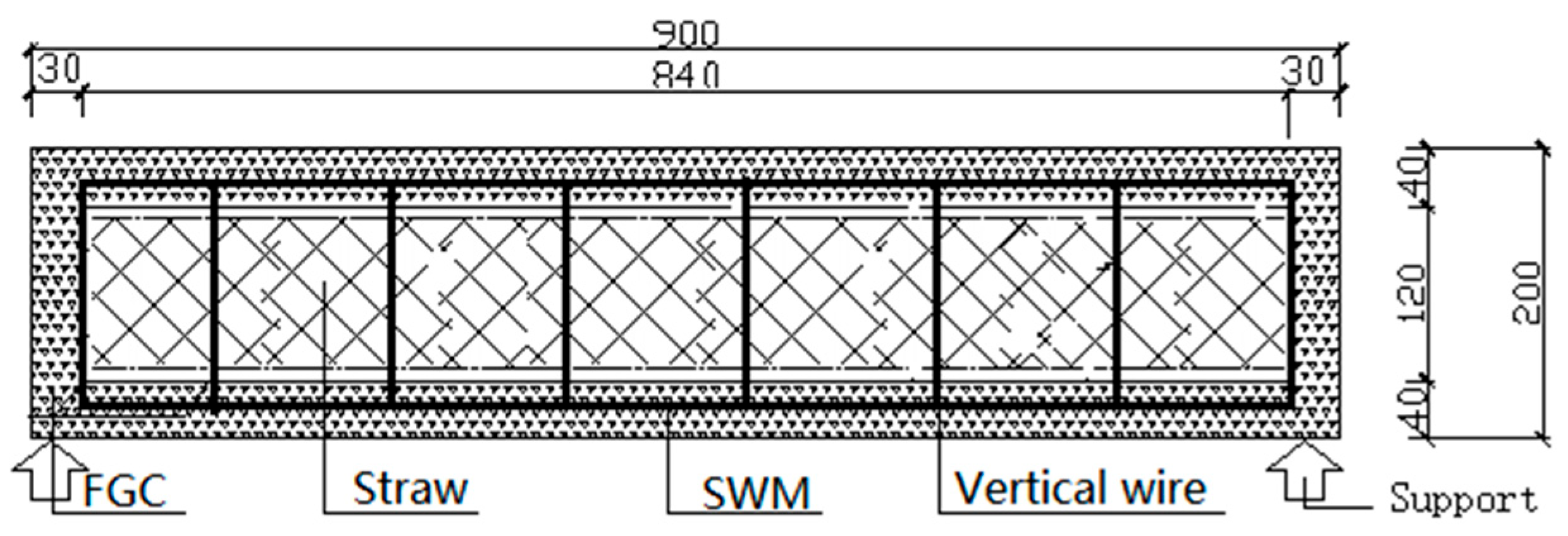
The composite SCSP comprised a straw sandwich layer and a SWM-reinforced FGC bearing layer. According to the previous research conducted by Gao et al. [
31], the sandwich plate was selected with the following specifications: The length of the SCSP was 900 mm, the width was 420 mm, and the thickness was 200 mm. Three SCSP specimens of the same size were made. The SCSP structure is shown in
Figure 2. The dimensions of each part of the SCSP are shown in
Table 3.
3.1. Prepare the Straw Sandwich Layer
First, the straw flakes were made. Using a freshly dried straw, a special fully automatic straw mat production equipment was used to press down on 840 mm long, 400 mm wide, and 30 mm thick straw flakes. These straw flakes were wet with water 24 h in advance to make them more uniform and dense when making sandwich panels. Four layers of the straw flakes were superimposed together, and the thickness of the straw layer was 100~120 mm. The edge of the straw mat was trimmed neatly, and the straw sandwich layer was compressed.
3.2. Erection of SWM
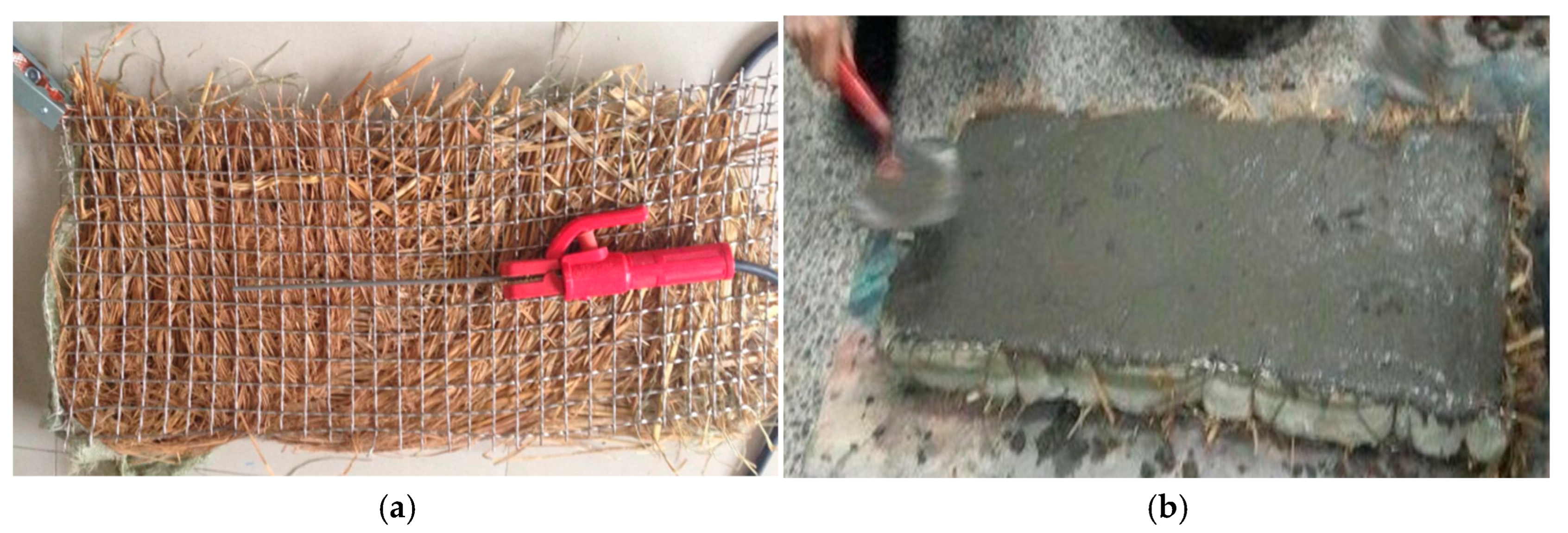
The SCSP was the same size as the straw sandwich layer. The straw sandwich layer was selected after production, and its surface was moistened with water, and the surface and edge were trimmed and smoothed. When the surface of the straw layer was slightly dry, 900 mm × 420 mm cold-drawn low-carbon SWM sheets were laid on both sides of the upper and lower sides, and vertical force bars were inserted between the upper and lower cold-drawn low-carbon SWM sheets for tying and fixing. After the upper and lower horizontal SWM was fixed, the side of the straw sandwich layer was closed by SWM welding.
3.3. Preparation of FGC
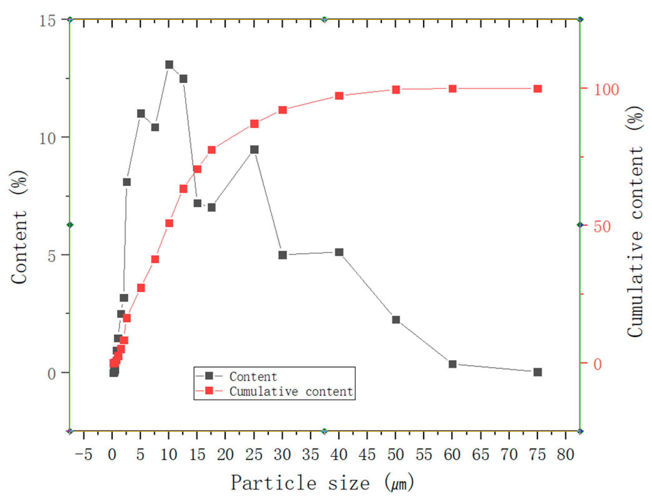
After the straw sandwich layer fixed to the SWMs was erected, the SCSP was prepared by spraying FGC. To ensure the workability of FGC, fly ash with 10% cement content was added. The particle grading curve of fly ash is shown in
Figure 3.
The water pressure and water consumption of FGC injection construction were adjusted before the construction started. The length and diameter of the FGC dry material conveying pipe were moderate, the water pressure in the jet tank was stable at about 0.5 MPa, and the appropriate spraying distance was maintained to minimize the amount of rebound aggregate of the SCSP. The FGC was sprayed uniformly from top to bottom along both sides of the SCSP, and the amount of FGC and the spraying time were adjusted at any time to ensure the surface of the SCSP was smooth and the FGC was dense and uniform.
The thickness of the panel FGC was 30 mm. The FGC of the panel surface layer was sprayed in two layers. The initial spray thickness was controlled at 15 mm. After the first layer of FGC was filled with density inside the SWM of the panel, the second layer of FGC was sprayed, also with a thickness of 15 mm. The upper side and two sides of the SCSP were coated with an iron trowel and pay attention to compaction and leveling. The spraying process parameters had a great influence on the bond strength between SWM and straw. Too high spraying pressure would cause concrete aggregate rebound and affect the interfacial bond strength between concrete and SWMs or straw. However, if the spraying pressure was too low, it affects the compactness of the FGC, thus reducing the strength of the concrete itself and the interfacial bond strength.
To ensure the quality of FGC in the process of spraying, the fluidity of FGC was controlled. The change in ambient temperature during the injection process was controlled. If the temperature was too high, the FGC would set quickly, and if the temperature was too low, the strength of the FGC would grow too slowly. This would have an adverse effect on the bond of FGC. At the initial stage of spraying, the bond between the straw layer and FGC was the main factor affecting the quality of spraying.
Before the initial setting of the FGC protective layer of shotcrete, the surface layer was compacted and brushed with a wooden shovel, and the maintenance was carried out after the initial setting. During the curing period, the indoor temperature was not less than 20 °C and was kept moist for 28 days. The preparation of the SCSP is shown in
Figure 4.
Three sets of 100 mm cube specimens were made by FGC. The specimens were cured under the same environmental conditions as the SCSP. The mechanical properties of the specimens were tested simultaneously with the SCSP test. The performance parameters of C30 concrete are shown in
Table 4.
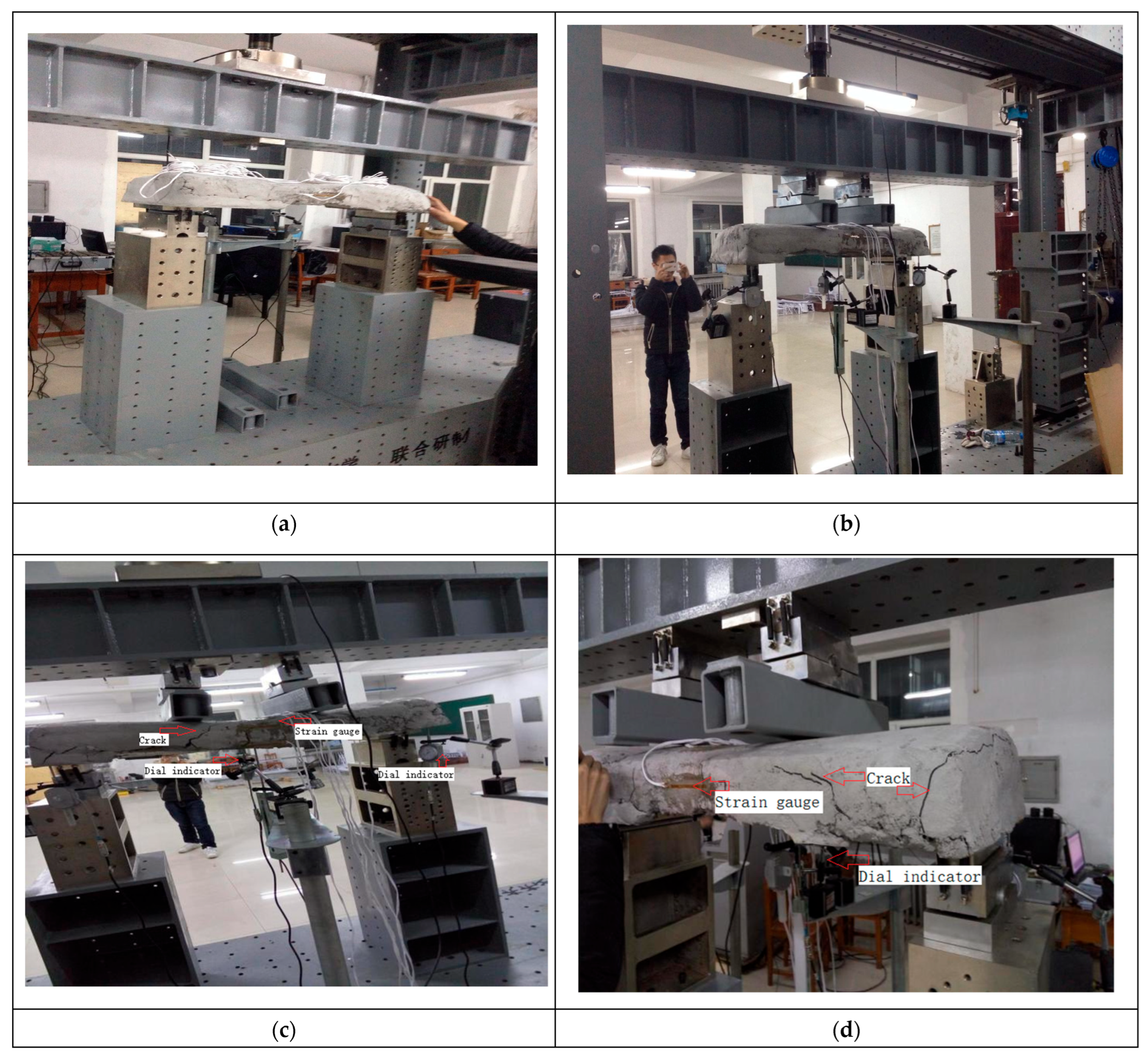
4. Loading Experiment
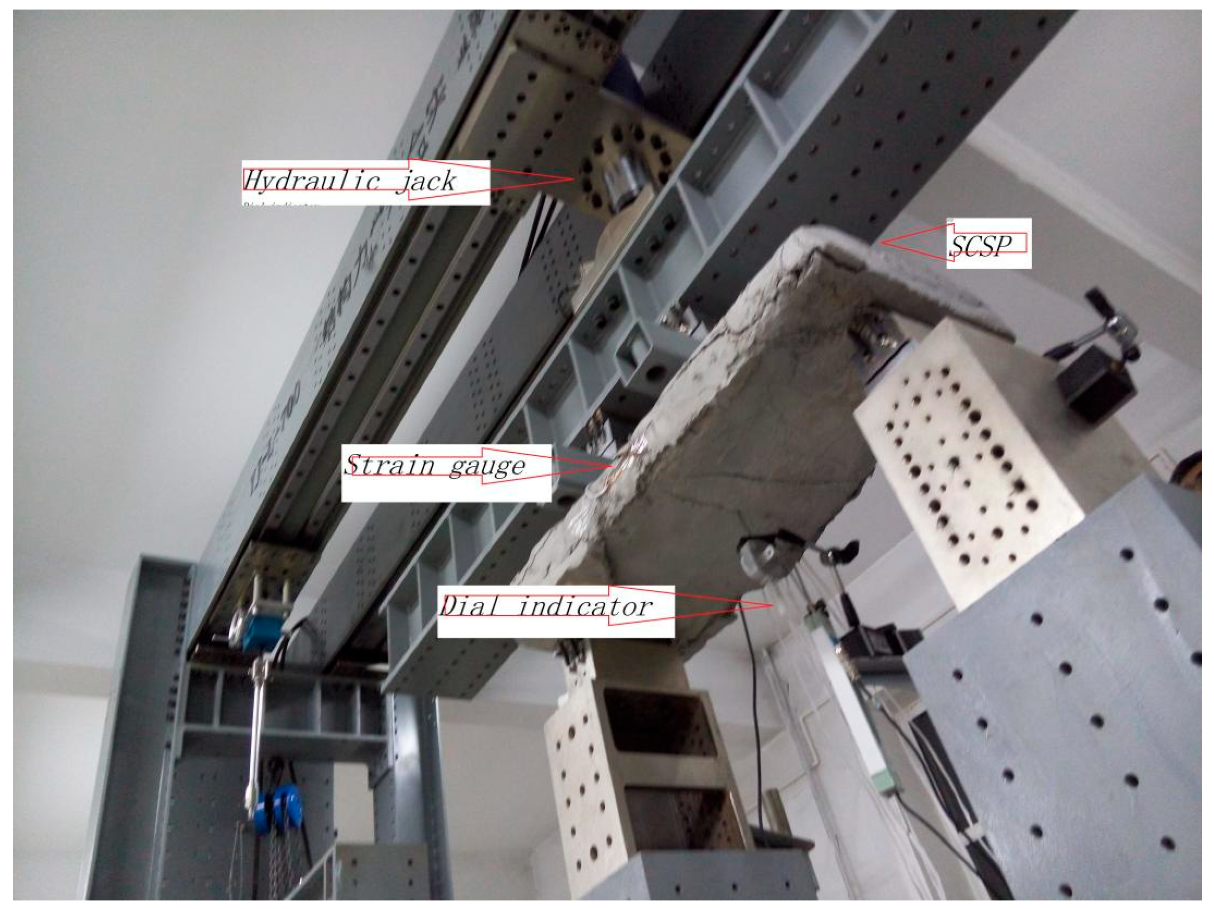
After the SCSP was prepared and cured for 28 days, the four-point flexural performance of the SCSP was tested. The actual deformation was measured by installing two deflection meters along the axial direction of the SCSP. The deflection of the SCSP supports and mid-span, the variation of strain at the top and middle of the panel, the width and distribution of cracks at the bottom, and the cracking load and ultimate load of the SCSP were tested. The main instruments used are as follows: YJ-L-700 structural mechanics combined experimental loading device, dial gauge (for measuring mid-span deflection), static resistance strain gauge, as shown in
Figure 5. J-L-700 is produced by Yantai XTD Test Technology Co., Ltd. (Yantai, China), which has a maximum test force of 700 kN. The mechanical dial meter produced by Shanghai Shangshen Co., Ltd. (Shanghai, China). has a measuring range of 0–5 mm, a division value of 0.001, and an accuracy of 0.0001. The static resistance strain gauge is ASMC5-8/16/32 produced by Jinan Sigma Co., Ltd. (Jinan, China).
After field measurement and weighing, the size of SCSPs conform to
Figure 2. The theoretical weight of the SCSP is 81.00 kg, and the actual weight is 80.36 kg. The actual weight of the SCSP corresponds to the theoretical weight. By calculation, the weight of a solid panel of the same size is 189.00 kg. The weight of a single panel is 57% less than that of a normal concrete panel of the same size. Four groups of concrete strain gauges were pasted in the middle span of the top surface of the SCSP, and they were numbered according to different positions of the concrete strain gauges, as shown in
Figure 6. The SCSP was installed on the test bench; the distribution beam, jack, and sensor were installed; and the concrete strain gauge and temperature compensation panel were connected with the static resistance strain gauge. According to the actual stress of the SCSP, the rolling hinge supports are adopted at both ends, and the loading pressure is carried out according to the simply supported panel. The distribution beam is equally divided on the longitudinal center line of the SCSP at 1/3 of the span, and the single concentrated load is divided into two equal concentrated loads. The loading condition of the specimen is shown in
Figure 5.
5. Calculation Model
According to the relevant provisions of concrete structure design code GB 50010-2010 [
32], a simplified calculation model of the ultimate bearing capacity of SCSPs is established. To simplify the calculation, the following basic assumptions were made for the SCSP. Because the straw core is located in the central axis of the SCSP and its elastic modulus is small, it has little influence on the flexural performance of the SCSP. The flexural resistance of the straw sandwich layer was not considered. The strain between the upper FGC layer and the lower tensile SWM complies with the assumption of the plain section. According to the test results, the stress level of concrete in the limit state of bearing capacity is very low, and it can be approximated that concrete is in an elastic state. The terms involved in the calculation are explained in
Table 5.
Based on the above assumptions, it can be seen from the analysis of the structure of the cross-section of the specimen that the bearing capacity of the SCSP is calculated by converting the original cross-section into a T-beam. The calculated cross-section after transformation is shown in
Figure 7. In the Figure b = b
1 + b
1 = 60 mm, b
f = 420 mm, h = 200 mm, h
f = t = 40.
According to the data in
Table 1 and
Table 3, the concrete strength is C30.
Only the lower part of the T-beam is considered, so the SWM protective layer is 40 mm.
And because
it belongs to the first category, and it is calculated directly according to the rectangular beam with width b
f and height h
f:
According to Formula (1), the following data can be obtained:
According to Equation (2), the following data can be obtained:
Due to the low reinforcement rate of the SWM, the neutral axis of the SCSP member has risen to the concrete layer of the compression area when it is damaged, and the anti-compression effect of the upper steel wire is ignored. The sign of failure of a member is that the tension wire is broken. The calculation and distribution diagram of the ultimate bearing capacity of SCSP is shown in
Figure 8.
Based on the simplified strain distribution diagram of the SCSP in
Figure 8, the relationship between the strain of the SCSP concrete and the strain of the steel wire is obtained, and Equation (3) is obtained.
Combined force Fc of concrete compressive stress in the compression zone of SCSP:
The resultant tensile stress of the wire is
According to the cross-section force balance F
c = F
s, x = 1.9564 can be solved. The ultimate flexural moment of the SCSP is:
According to the Equations (3)–(6), the following data can be obtained:
6. Results and Discussion
The SCSP loading test was sampled 256 times, once every 5 s. The loading rate was controlled by the displacement in the panel span and was set to 0.5 mm/min. The loading range was 0~73 kN, and correspondingly, the mid-span flexural moment of the SCSP was 0~11 kN·m. The experimental results and load–strain curves of the upper panel show that the loading process of the SCSP can be divided into three stages: elastic working state, cracking state, and failure state at 7.5 kN·m and 10.9 kN·m, as shown in
Figure 9a,b. The horizontal coordinate is the mid-span flexural moment value in kN·m, and the vertical coordinate is the measured deformation reading in μm/m. As can be seen from the Figure, the flexural moment depends on the elastic deformation of concrete at the initial stage of loading. Before the mid-span flexural moment to 7.5 kN ·m, the SCSP is in a fully elastic working state, at which time, the FGC and SWM are mainly jointly stressed. When the mid-span flexural moment of the SCSP was 7.5, the strain shown by the 1#, 2#, 3#, and 4# strain gauge was −308, −525, −488, and −559 μm/m, respectively. When the mid-span flexural moment is less than 10.0 kN·m, the deformation of the SCSP begins to accelerate, but it is not cracked, and the force of the SWM gradually increases. When the mid-span flexural moment exceeds 10.0 kN·m, cracks appear in the panel, and the SWM is fully stressed. The bearing capacity continues to increase, but the cracks increase, indicating that the SCSP is close to the failure state. It can be seen from the curve that the changes in different positions on the upper part of the SCSP are the same.
Figure 10 shows the mid-span load–deflection curve, whose variation rule is consistent with panel deformation.
From the experimental data and the curve drawn, it can be seen that the SCSP loading to failure is divided into three stages. The first stage is the elastic working state. At the beginning of loading, because the flexural moment is small, the strain of each fiber measured along the height of the panel is also small. Because the strain is very small, the concrete is basically in the elastic working stage, and the stress is proportional to the strain. At this time, the deflection of the panel is small, and the increase in deflection is approximately linear with the increase in load. The concrete is not cracking at this time. The second stage is the cracking state. After concrete cracking, the tensile steel-wire condition yields. At the section with the weakest tensile strength, when the tensile strain value of the edge fiber reaches the ultimate tensile strain of concrete, the first crack appears. The first crack generally appears in the middle of the span or where the concentrated load acts, and once the crack appears, it runs through the entire width of the panel and extends to the top of the lower concrete surface. After cracking, the growth rate of panel deflection increases obviously, and the corresponding load–deflection curve shows an obvious turning point. As shown in
Figure 10a,b. It can be inferred that at the crack section, as soon as the concrete cracks, most of the tension originally borne by it is transferred to the steel wire, and the tensile stress is almost entirely borne by the SWM. After cracking, as the next level of load continues to increase, new cracks appear, the first crack width has developed, and then, with the increase in load, the main crack extends to the upper concrete surface. The second stage is the stage of crack occurrence and development, in which the panel is working with cracks. The third stage is the destruction of the SCSP. When the mid-span flexural moment of the SCSP exceeds 10 kN·m, the wire reaches the yield strength and the SCSP enters the third stage. At this stage, the crack width increases significantly, and the compression zone height decreases further. When the ultimate flexural moment is reached, the strain of the steel wire increases, the mid-span deflection of the corresponding panel increases, and the test load decreases slightly. Finally, the crack width reaches 3~4 mm, the wire reaches the limit tensile strain, and the SCSP is destroyed.
To sum up, the panel has the following characteristics in terms of crack development and distribution, load–deflection curve, and strain variation trend in section concrete. About 70% of the general ultimate load, the specimen cracks, and cracks generally appear in the mid-span position or concentrated load action; cracks are typical normal section flexural vertical cracks. Due to the lower concrete surface, the layer is thin. As soon as cracks appear, they penetrate the lower surface layer, so that the concrete in the pull area completely exits the work, and the SWM plays a role in limiting the development of cracks. Crack width controls the normal use limit state. Before failure, cracks extend to the upper concrete surface. Bearing capacity limit state, each panel has about 3 to 5 cracks, evenly distributed in the span and concentrated load. The distribution diagram of panel cracks is shown in
Figure 11a–d.
In this study, the flexural strength and crack development of SCSP were tested and analyzed. This mainly depends on the SWM in the lower part of the SCSP to play a decisive role, and it depends on its good bond to the concrete. In fact, the shear resistance of the SCSP can be increased by the connection of vertical steel wires and the thickness of the concrete layer. Due to the good bond between SWM and concrete, the crack expansion on SCSP surface is limited, and the ability of the panel to resist bending moment and shear force is greatly improved.
Compared with similar panels [
4,
20,
21], the SCSP in this study adopts crop straw as the sandwich layer to make full use of agricultural waste, which is in line with the concept of sustainable development and circular economy. However, further research will be carried out on the fire resistance, thermal, and acoustic analysis of the material.
The SCSP can consume a large amount of straw waste. Through the collaborative stress of steel mesh and concrete layer, it will be very suitable for engineering applications of roof panels in rural residential buildings in cold areas in the future.
A calculation model is also provided for the SCSP. The purpose of this model is to verify the experiment and provide a theoretical calculation method for similar SCSPs. The comparison between the experimental results and the calculated results provides a useful validation for the model. The application of the SCSP is a key aspect of the research, as it affects its mechanical properties and its location. The study addresses the horizontal bending behavior, and the application of the SCSPs will position the roof panels as horizontally stressed.
The comparison between the ultimate flexural moment measured by the test (TM) and the ultimate flexural moment obtained by the two simplified calculation methods is shown in
Table 6. It can be seen from
Table 6 that the calculated ultimate flexural momentis similar to the test results. The average error is 2.99% and 9.41%, respectively, by comparing the experimental values with the two calculated values. The results obtained by using the two models are in good agreement with the experimental results. The ultimate bearing capacity obtained by the second method (CM
2) is slightly larger than that obtained by the first method (CM
1). It has a percentage error of 6.2%.
The main reasons for these errors include the following: the defects of concrete compactness, the deviation of component size, and the deviation of steel-wire mesh position; The deviation between the assumption of plane section of the model and the actual situation is calculated; The error caused by the difference in simplification between the two calculation models. It can be seen from the related equations of the above two calculation models that material properties have a great impact on the equations. For example, when the SWM diameter or yield strength spinning increases, the flexural moment resistance of the SCSP increases significantly. In addition, the thickness of the upper FGC layer of the SCSP also greatly affects its flexural strength. In contrast, the thickness of the lower FGC layer of the SCSP has little influence.
Table 6 shows the experimental and calculated ultimate bearing capacity of the SCSP.
In this study, the structural properties of the panels are discussed, with emphasis on the flexural properties. Other mechanical aspects, such as shear force, compression performance, thermal, acoustic, and fire performance have not been thoroughly analyzed, which is the limitation of this study, and will be further studied in the future.
7. Conclusions
The SCSP bears the load mainly through the upper and lower steel SWM and the vertical steel wire between the mesh, and the load is borne by the action of FGC. The flexural moment load is mainly borne by the FGC on the upper part of the SCSP and the SWM on the lower part.
The simplified calculation model is consistent with the experimental data. The average value of teaching documents measured by experiment is 11.37 kN·m. The ultimate bending moment value obtained by the first method is 11.71 kN·m. The ultimate bending moment value obtained by the second method is 12.44 kN·m. It shows that the two simplified calculation methods can reflect the actual flexural resistance of SCSP well.
The comparison of experimental results shows that the thickness of FGC and the number and direction of MSW are related to the bearing capacity of SCSP. The flexural resistance of SCSP has little relation with the straw of the sandwich layer.
The SCSP has characteristics of light weight, moderate bearing capacity, good cracking resistance, and low cost. The SCSP is light in weight compared to similarly sized concrete slabs. The weight of a SCSP is 57% less than that of a normal concrete panel of the same size. The calculation also shows that the bearing capacity of the SCSP is equivalent to that of similar size concrete slab. As the amount of concrete is reduced by 50%, the cost is reduced accordingly.
At the same time, due to the material characteristics of the straw, the thermal and acoustic properties of the SCSP are also beneficial. The SCSP makes full use of residues such as straw and fly ash, which conforms to the concept of circular economy and sustainable development.


