1. Introduction
As geospatial technology and infrastructure advance, and new types of spatial data such as three-dimensional (3D) models become available, traditional two-dimensional (2D) Geographic Information System (GIS) frameworks and applications have also gradually adapted to 3D environments in recent decades [
1,
2]. This advancement offers a viable platform for constructing a realistic environment to simulate and analyze sophisticated spatial problems in conjunction with information and communications technologies (ICT), especially for city modeling [
3,
4]. Virtual 3D city models can not only represent geo-referenced objects of a large urban area systematically [
5] but also enable various human–environment applications. For example, landscape management [
6], determining escape routes inside and outside of buildings [
7], and accessing environmental equity of sunlight [
8] can be implemented using these types of 3D-GIS platforms. In a 3D GIS or city model platform, the building model is one of the most important and attentive elements, as buildings are the most ubiquitous objects in a real-world city. The Open Geospatial Consortium (OGC) CityGML specification [
9] defines four levels of detail (LOD) to describe building models in different scales and accuracies depending on data sources and purposes. Viable methods have been developed to create building models at different LODs, i.e., LOD0-LOD3. For example, LOD1 and LOD2 building models can be produced using large-scale aerial photographs [
10], while Light Detection and Ranging (LIDAR) point clouds and close-range images can be used to generate LOD3 building models [
11]. Because LOD0-LOD3 models can have indoor and outdoor elements, the previous LOD-4 model is dropped and replaced with indoor variables [
9,
12].
In addition to the GIS or spatial perspective, Building Information Modeling (BIM) is another popular approach for describing buildings in the construction and civil engineering domain, with a focus on building model behaviors [
13]. A common objective of BIM is to facilitate effective management throughout the life cycle of building objects [
14]. BIM uses project-based approaches to construct building models instead of object-oriented building models commonly adopted in the GIS domain. For example, the LOD in BIM describes the level of “development” of a building during its life cycle, and the converting of the LOD between CityGML and BIM is essential [
15]. Therefore, BIM and GIS-based building modeling systems can be considered interoperable and applications integrating BIM and GIS will provide more comprehensive quantitative geospatial data and non-spatial building attributes for better simulations and analyses [
16,
17].
An emerging topic in related fields is how to effectively utilize geospatial data and systems to address public safety issues and support emergency services, especially in complex environments. In a real-world emergency situation, the challenge is to reach the most effective and timely decisions, especially when data and information are limited [
18]. Conventional two-dimensional (2D) floor maps, which simplify 3D environments, may not be able to provide adequate detailed semantic information. For example, Hamieh et al. [
19] projected specific elements extracted from the 3D environments onto 2D floor maps and incorporated their BIM-based information for indoor path planning. Therefore, it may be difficult for firefighters to carry out search-and-rescue missions using only 2D maps and spatial information. Similarly, evacuations and route planning in complex compounds and buildings may become a real challenge for both administrators and the public and can potentially cause serious public safety issues for residents and passengers. To address these issues, a few researchers have proposed and successfully demonstrated that 3D spatial information can be very useful for navigation and emergency response in indoor and outdoor environments [
9,
20,
21,
22], especially when combined with spatial analysis and decision support systems.
Moreover, Macatulad and Biljecki [
23] apply Big Data and geospatial artificial intelligence (GeoAI) solutions to large-scale 3D building models to provide a framework for disaster management. GeoAI-based approaches, however, require a large amount of training data such as hundreds of thousands of images to train a model beforehand. Acquiring adequate training data for indoor scenes and developing a desirable model remains challenging, and such procedures increase both time and monetary costs. Thus, GeoAI-related methods may not be applicable to a limited amount of spatial data.
Although advanced decision support systems for emergency management using GIS and ICT have been developed, additional information is still necessary, especially in 3D environments [
24]. For instance, integrating RFID, LIDAR, or images with the BIM/IFC framework for indoor navigation is highly beneficial for achieving precise localization [
24,
25,
26]. Real-time communication between a server and a client may also be required to guide the client in some emergency situations [
27]. With 3D building models and information-based attributes, the integration of GIS and optimization algorithms can enhance the effectiveness and efficiency of route determination in emergency services applications, such as evacuation or search-and-rescue decision support [
28,
29].
Digital city models and road networks have been successfully applied to solve best route problems in transportation within the spatial optimization domain [
30]. Several algorithms have been developed, including genetic algorithm (GA) [
31], particle swarm optimization (PSO) [
32], and artificial bee colony (ABC) algorithm [
33,
34,
35], to address global issues by using 2D maps, such as land-use allocation and texture classification. Maboudi et al. [
36] compare the capacity of several route-planning algorithms, and ant colony optimization (ACO) [
37,
38] is considered having a great potential for solving routing problems in complex environments [
39]. ACO simulates the food-searching behavior of ants and determines the optimal route from one node to another. This heuristic algorithm is versatile, robust, and population-orientated, making it adaptable to variant conditions and features. It has been customarily adopted and modified for path planning applications, such as solving the Traveling Salesman Problem [
40,
41,
42,
43], or for mobile robot path-finding [
44]. In addition to globally solving optimal route problems, ACO can further explore the path-finding procedure of each ant, enabling local searches and suboptimal investigations.
ACO has also been successfully applied to various routing-related problems, such as multi-depot vehicle routing [
45] and improving UAV paths when searching for lost or trapped people in mountainous areas [
46]. In a dynamic environment, ACO, when integrated with local search operators, can achieve excellent performance [
43]. For emergency service decision support, Liu et al. [
47] demonstrate the capability of combining GIS and ACO on safety and emergency responses, and Tashakkori et al. [
48] investigate the issues of using ACO for 3D indoor search-and-rescue operations.
Because ACO uses pheromones as a medium for communication among ants, this study further personifies ACO with human behavior when searching for the best route in complex indoor environments. These environments are represented using OGC CityGML interior building models with spatial and non-spatial attributes for emergency services. The suboptimal investigation, which shows the entire route-searching procedure of each ant, is also considered analogous to the behavior of a single person in a 3D environment. In addition to the geometric distance between two nodes, a cost distance concept is proposed to consider the non-geometric or non-spatial attributes in the developed route-searching system. Simulations of passenger evacuation in a complex underground train station are performed as test cases to validate the effectiveness of the developed algorithms for indoor routing strategy support. The experimental results demonstrate the potential and feasibility of integrating spatial geometry and information-based attributes in realistic spatial analysis in 3D environments.
This study aims to perform spatial analysis with detailed indoor building models and attributes for emergency evacuation decision support. Unlike conventional spatial applications that primarily rely on geometric information, this research further incorporates non-geometric attributes as environmental factors into the spatial application system. As a result, spatial applications and analysis can be assessed by considering more real-world elements. With such a virtual system, spatial simulations can be conducted before practical implementations, providing an overview of the entire scenario and reducing unnecessary costs. This research highlights three key aspects: (1) integrating spatial information and non-geometric attributes into a single virtual 3D platform for easier visualization and access, (2) enabling a more comprehensive understanding of the environment compared to traditional 2D maps, and (3) simulating emergency evacuation by modeling and personifying ant behaviors and digitizes environmental factors to mimic human’s reactions for optimal route selection.
The rest of this paper is organized as follows.
Section 2 describes the 3D modeling of indoor environments.
Section 3 presents the modified ACO algorithm and procedures.
Section 4 shows the experimental results and discussions. Finally, conclusions are drawn in
Section 5.
2. Three-Dimensional Modeling for Complex Indoor Environments
In recent years, BIM has become popular in architecture and construction for modeling buildings and their elements. The most commonly used data format in BIM is the Industry Foundation Classes (IFC 23) standard [
49] developed by buildingSMART. On the other hand, OGC CityGML is a popular schema for digital city modeling and can be easily ingested into most 3D GIS systems. Both IFC and CityGML describe 3D building models in object-oriented manners, but they have different class/object definitions due to their different target users and usages [
50]. In addition, different LODs in IFC and CityGML may also consist of dissimilar contents and object types. Therefore, it may be useful to generate a lookup table of common IFC and CityGML entities (as listed in
Table 1) for converting from one to the other.
The relationship between CityGML and IFC entities is not necessarily one-to-one. For example, a gml::BuildingInstallation may come from IfcBeam, IfcColumn, or other IFC entities. Therefore, the converted CityGML entity should store the source IFC entity as a text annotation to retain the information as completely as possible. Similarly, when an IFC entity can be mapped to multiple CityGML entities, the correct mapping should be determined using geometric and other IFC attributes. For example, an IfcSlab can be a floor or ceiling, but a converter may use the direction of the normal vector obtained from IfcBuildingStorey to determine whether a slab should be converted to a ceiling or a floor surface in CityGML.
In addition to entity conversion, another inter-operability issue between IFC and CityGML is the coordinate system and model geometric representation transformation. A BIM/IFC model is in a local coordinate system, whereas an OGC/CityGML model is usually defined in the world coordinate system. To transform an IFC model to the world coordinate system used in CityGML, an affine transformation consisting of a scale factor, a rotation matrix and a displacement vector should be adequate. The transformation from a IFC coordinate,
, to a CityGML coordinate,
, can be represented as Equations (
1) and (
2), where
S is the scale factor;
R is the rotation matrix with a rotation angle of
and
is the displacement vector.
In CityGML, boundary representation (B-rep) is commonly used to describe 3D models, so a solid body is represented by faces, edges, and vertices. Models represented using B-rep can store detailed geometric and topological information about the objects. However, most parametric IFC model objects are defined using swept solids and constructive solid geometry (CSG) boolean operations. Converting an IFC model to CityGML requires transforming swept solids to B-rep-based models. The process can be summarized in five steps [
51]: (1) extracting geometric information (local origin, swept area, depth, direction etc.) from IFC objects; (2) calculating local coordinates of vertices; (3) transformation from local to world coordinate system; (4) generating the GML object model; and (5) generating geometric tables of vertices, edges, faces, and bodies. The nodes of objects can be extracted from corresponding IFC entries (such as origin coordinates, sweeping path and directional vector) and converted to the transformed coordinate system using Equation (
3),
where
D is the sweeping path distance and
is the directional vector of sweeping. Detailed explanations of the mentioned transformation steps can be found in the references and are not repeated here.
Depending on the LOD, a BIM/IFC model can be very complex, comprising many objects, which may result in a large CityGML model. It is often practically necessary to simplify the converted CityGML model in order to improve the efficiency in subsequent analyses.
Figure 1 displays an indoor model and its simplified version. The original indoor model consists of many minor structures that are not particularly crucial (at least not for navigation or emergency services) but may reduce the computational efficiency of subsequent analyses substantially. After simplification, the model is more concise but still preserves essential geometric properties and attributes that are adequate for spatial analysis.
For indoor navigation and emergency services, it is also useful to convert BIM/IFC models into OGC/IndoorGML [
52], as demonstrated in [
21]. IndoorGML is a data model based on GML 3.2.1 for indoor spatial information and is specifically designed for indoor navigation applications. An IndoorGML model is composed of Core and Extension modules. The Core module stores the model’s geometry and topology as a Node-Relation Graph (NRG) based on the structure space model framework, while different thematic data and information are kept in Extension modules, such as the Navigation Module for indoor network, routing, navigation, guidance, and related purposes [
52,
53].
There are three primary steps in converting a BIM/IFC model to OGC/IndoorGML. The first step is the coordinate system transformation, which is identical to the transformation procedure described above for IFC to CityGML conversion. The second step is the topology transformation, i.e., identifying and connecting the nodes of the indoor network. The nodes are identified from relevant IFC entities, such as
IfcSpace,
IfcOpenElement and
IfcCorridor. Then, the nodes are connected by searching the adjacent space of opening objects (e.g., doors) and the topological relationships, which can be extracted from corresponding
IfcRelSpaceBoundary entities. Finally, the indoor network nodes and connections (edges) are exported using the IndoorGML schema to form a complete IndoorGML model.
Table 2 summarizes the relationships between common IFC and IndoorGML entities of relevant element types. One thing to note is that after the conversion, it may be necessary to further manually remove or edit faulty or unreasonable network nodes and connections in the generated IndoorGML model to minimize biases and errors in subsequent analyses.
3. Ant Colony Optimization and Spatial Analysis
Ant colony optimization (ACO) in route searching imitates the behavior of natural ants searching for food. In natural ant communication, pheromones play an important role and artificial ant systems were proposed [
37,
54] to simulate ants’ behaviors. In general, in an ACO system, artificial ants are considered to have memory in a time-discrete environment. Take the case illustrated in
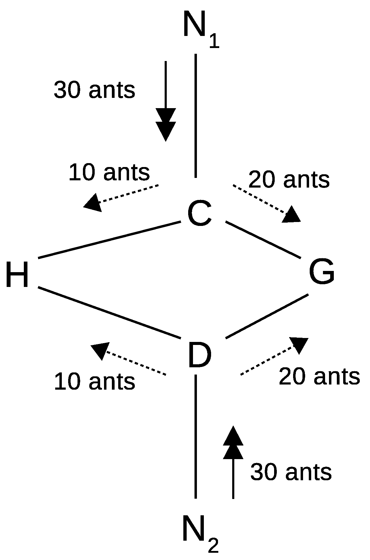
Figure 2 as an example: at the beginning of a “best-route” (shortest route) determination problem, when reaching an intersection (Node C or D), an ant may randomly select either the left or right route. However, as time passes, more ants may move toward the roads with shorter distances (CG and DG, which result in higher “pheromone” density), thereby forming the shortest route network N
1→C→G→N
2, and vice versa.
Because the pheromone trail intensity varies over time, two elements should be considered in the route-searching system: the pheromone evaporation rate,
, and the distance between two nodes. Taking a segment (CH) as an example, the trail intensity a single ant leaves can be expressed by Equation (
4) using a constant
Q and the tour length of the
k-th ant,
, if the ant takes that segment. When other ants select the same segment, the pheromone density accumulates as Equation (
5) based on the number of ants (
k = 1, …,
m). As a result, the pheromone intensity update function can be interpreted by the accumulated pheromone with the evaporation rate as Equation (
6) during a period of time (from
t to
t +
n).
According to the trail update strategy [
39], the pheromone concentration is developed into a probability function for route selection, as described in Equation (
7). In this equation, a collection of nodes,
, contains the candidate locations for an ant to move from one node to another. The nodes that have been already used should be excluded from the list as a node can be selected only once. A group of visibility factors,
, can then be generated based on the distances from the current location to the next reachable candidates [
38]. The parameters
and
represent the relative importance of trail intensity and visibility in the probability determination [
45,
47,
55]. For the parameters, this study empirically sets the pheromone evaporation rate (
) to 0.5, and the two hyperparameters
and
to 1 and 5, respectively.
Most ACO-based emergency evacuation applications might focus only on random swap and random insertion methods without incorporating the 3D models and attributes [
34]. To better account for the complexity of the real-world indoor environment, this research proposes an additional 3D environmental impact parameter,
, based on quantitative 3D information. The parameter is used to quantify the relative impact of spatial complexity in the route selection process. For instance, a personified ant cannot penetrate a wall, but it can open a door or a window to move from one node to another in a 3D indoor environment. Accordingly, the environmental impact parameter of a door can be set relatively higher than a wall when calculating the probability function for route selection.
Figure 3 and
Table 3 illustrate an example of different information-based attributes that distinguish different interior objects by the proposed
in a CityGML indoor building model. As displayed and noted in the figure, the room is surrounded by brick walls with a door and an air-tight window. The door is the easiest entrance and exit point of the room so it has the highest
of 1. The wall is usually difficult to break; therefore, the
of the wall is relatively low (0.3), while the
of the window is somewhat in between (0.5). The values of the environmental impact parameters are empirical and should be adapted according to different circumstances.
Distance is an important factor when determining the pheromone density and the probability of route selection in ACO. Instead of using the Euclidean distance between nodes, this study utilizes the cost distance that takes information-based attributes into account. The cost distance,
between two nodes is determined from its Euclidean distance,
, with two attribute-dependent factors,
and
, as stated in Equation (
8). The attribute-dependent weighting factor,
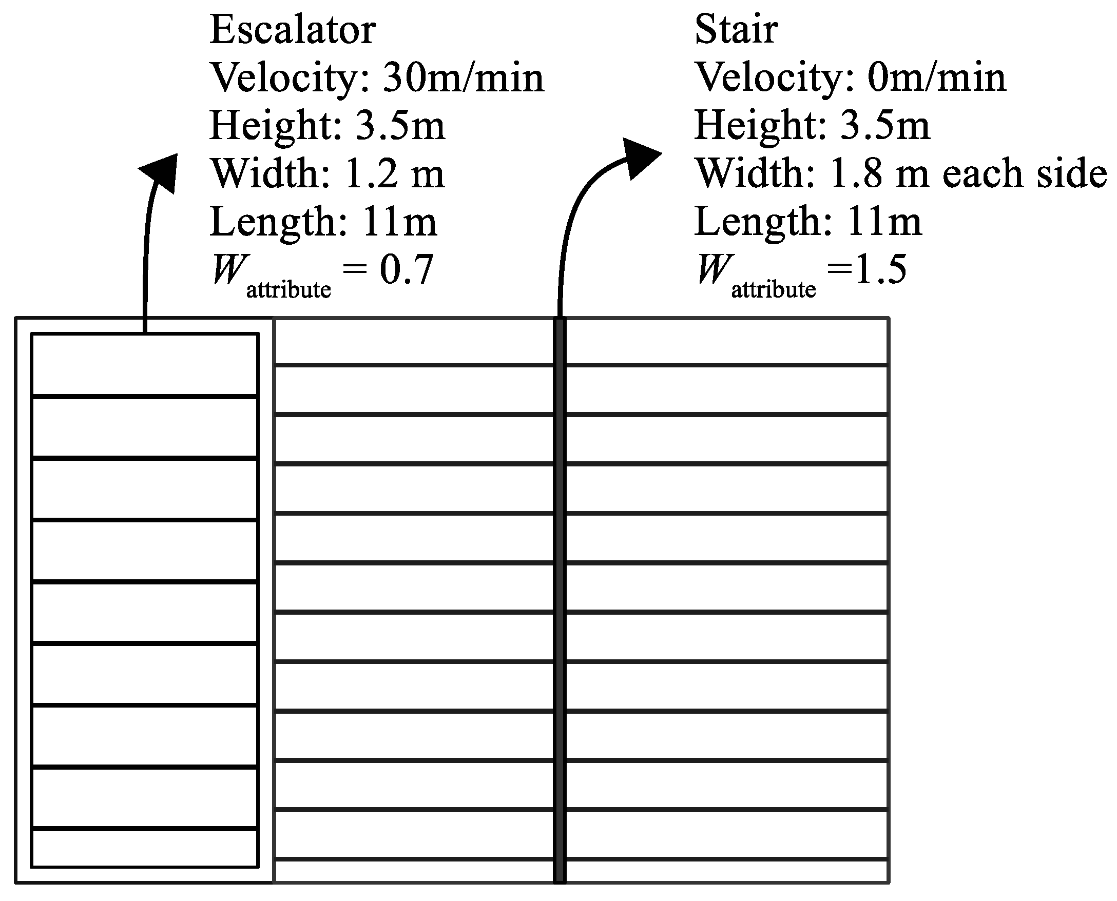
, accounts for the relative effort required for movement by different means. For example, in a subway station, an escalator may be built alongside a stairway, as shown in
Figure 4. The physical effort of taking the escalator or climbing the stairway may be different for a passenger to move from one floor to another. In this scenario, the effect of such non-spatial attributes (escalator or stairway) can be realized using the weighting factor; however, if the escalator is turned off (not moving), the weighting should be adjusted to be approximately identical to that of the stairway. Similarly, if an event or obstruction (e.g., a locked door) blocks or hinders the traffic between two nodes, a constant factor,
, is added to increase the cost of the distance.
Based on ACO and the proposed cost distance, a dynamic system is designed to optimize the route selection. The system uses the traffic flow concept similar to [
56,
57] to describe the effect of accumulated pheromone trails on the cost distance. This mechanism controls the in-and-out volume [
56] of each candidate route with full cost limitation (
) and low-cost permission (
).
Figure 5 illustrates the dynamic cost accumulation and the route selections in the time-discrete system. This example displays an escalator (
and
) as well as a stairway (
and
) for N-ants to decide the direction. At the beginning (t = 0), the cost distance to select the escalator is smaller than the stairway, i.e.,
. The first ant goes through the escalator and adds additional costs to the cost distance as Equation (
9).
The dynamic cost used in this study consists of four elements to control the best-route selection strategy. The number of ants (
n) indicates the continuous entry into either the escalator or the stairs. Normalizing
with the maximum allowed number of ant (
T) prevents the dynamic cost from increasing too rapidly and exceeding the upper limit too soon. The cost distance from the previous ant represented by
leads to the accumulation when an ant selects its path. For the first ant, this variation can be set as Equation (
8) to start the cumulative cost in
Figure 5a. As more ants go through the escalator, its accumulated cost increases, as displayed in
Figure 5b. The
is the cumulative cost when the number of ants (
n) equals the maximum allowed number of ants (
T) and can be calculated by Equation (
10). When the accumulated cost of the escalator reaches
, the next ant turns to the stairway and adds its cost to this route, as illustrated in
Figure 5c. Simultaneously, the cost of the escalator starts to decrease by the same amount added to the stairway,
, as described in Equation (
11). In this mechanism, a damping factor
g (where
) is used to reduce the accumulated cost of the escalator. When the accumulated cost of the stairway route reaches its upper limit (
), a similar process begins, as shown in
Figure 5d. Therefore, load-balancing [
39] both routes can control the costs and optimize the dynamic route selection system as well as the in-and-out flow.
4. Experimental Results Analysis and Discussions
The described indoor modeling, ACO, and spatial analysis algorithms were implemented and applied to a test case of dynamic emergency evacuation simulation in a complex train and subway station (Taipei Main Station). The station is one of the largest in Taiwan, with four rail systems converging here, including Taiwan Railways, Taiwan High-Speed Rail, and two Taipei Metro subway lines. The main building of the station is seven stories above ground and four stories underground. There are also several underground tunnels and walkways connecting the station to nearby shopping complexes. The station serves at least hundreds of thousands of passengers every day. Therefore, it is critical to have an effective and efficient evacuation strategy during an emergency. The experiment carried out in this study simulated directing passengers to move from an underground platform floor to ground exits when there are multiple options, e.g., stairs and escalators, during an emergency evacuation. In this example, 3D indoor building models, spatial and non-spatial attributes, relative impacts of interior facilitates and environment, etc., were all taken into account in the cost distance determination to distinguish the spatial complexities in the route selection operation.
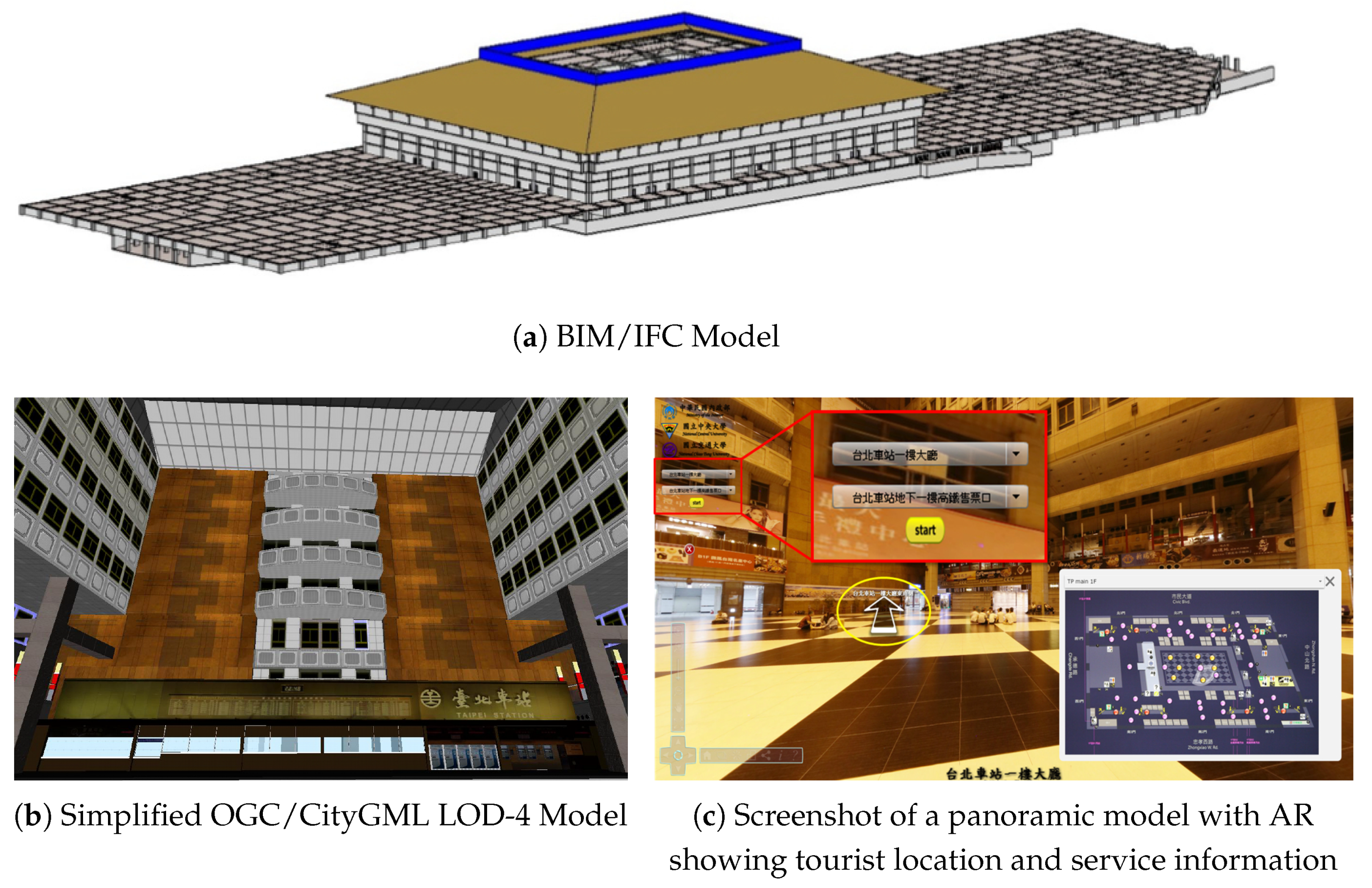
As shown in
Figure 6a, the original building model of the study site was created in BIM/IFC format and was converted to OGC/CityGML models with multiple levels of detail, including a simplified indoor model as displayed in
Figure 6b, and all necessary attributes. In addition, an app with Augmented Reality (AR) functionality on the panoramic model of the station, as illustrated in
Figure 6c, was also created to be used on passengers’ mobile devices for visualization, indoor navigation and evacuation guidance based on the model and ACO analyses in case of an emergency.
The creation of the OGC/CityGML model successfully demonstrates that the proposed methodology is capable of handling real-world projects. Since the primary pathways in Taipei Main Station are stairways and escalators, this study designs two simple test scenarios shown in
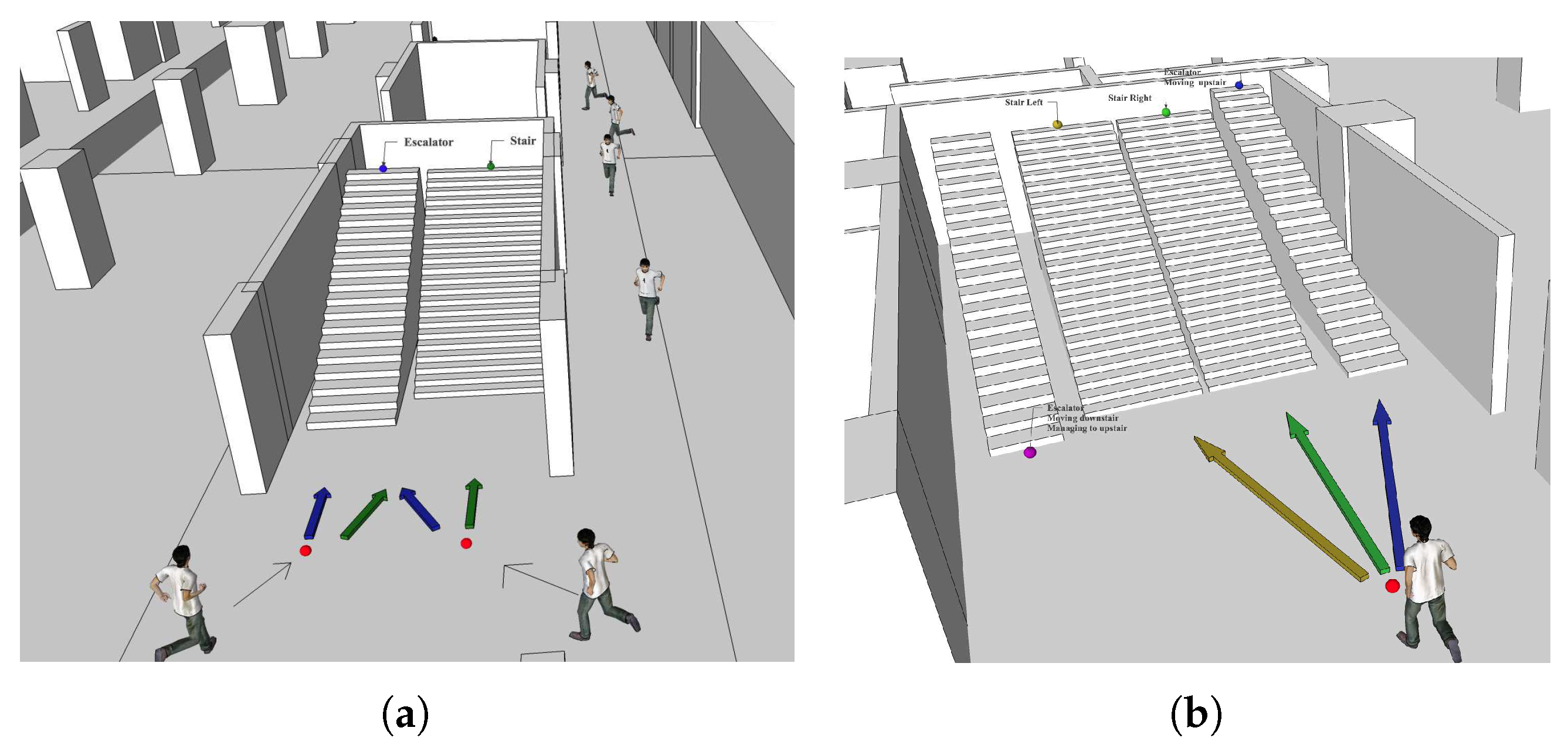
Figure 7 using only escalators and stairways to illustrate the dynamic routing model for emergency evacuation and to validate the proposed approach. The parameter settings of all EIs can be referred to
Figure 4. The route-searching behavior of an individual passenger can thus be simulated and investigated through the personified ACO system. More sophisticated experiments could be built upon the work presented here if necessary.
In the test case shown in
Figure 7a, it is assumed that there are 200 ants (passengers) to be evacuated (i.e., the number of ants is 200). At one of the IndoorGML nodes connecting the underground level to the floor above, the passengers can choose to either go through an escalator or a stairway next to it. Dynamic route selection in this experiment is based on the cumulative cost of the escalator and the stairway. The environmental impact factors included in the probability function as described previously are used to showcase the passengers’ interactions in the cost accumulation mechanism.
Table 4 lists the initial attribute-related weights and other parameters used for computing the cost distance, including the
,
, and the number of allowed passengers. The constant
in Equation (
8) can be set to any value smaller than
. In this test case, this study sets the constant to one-tenth of
to simplify the computation. The exiting ratio controlling factor (g) of both paths is set as 0.6 to implement the cost-depending evacuation.
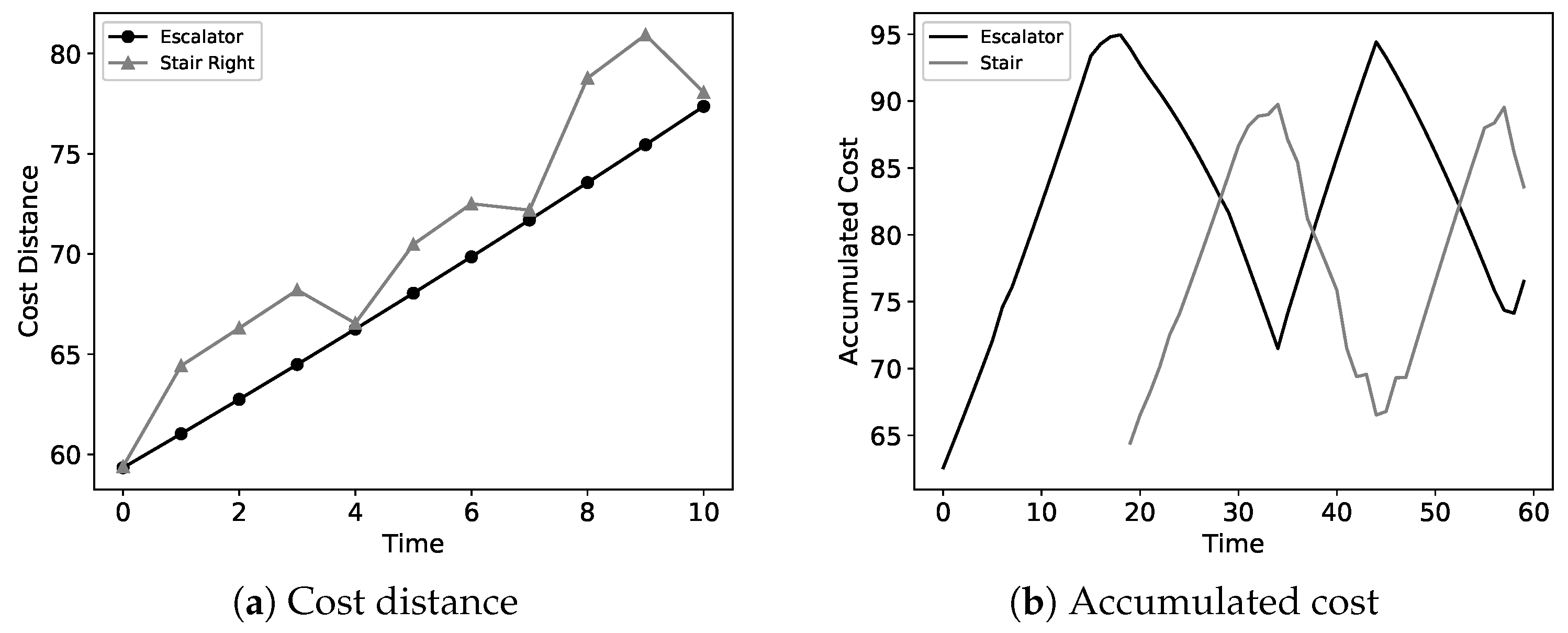
Figure 8 illustrates the evacuation scenario described above, the cost distances, and the accumulated costs of both routes with thresholds to control the in-and-out-flows. At each time point, an ant (passenger) compares the costs of all available routes and selects the one with the lowest cost. As shown in the figure, the initial cost distance of the escalator route is lower than that of the stairway, so an ant goes upstairs by the escalator. As more ants move into the escalator, the accumulated cost increases until a later ant turns to the stairway route. At this point, the accumulated cost of the stairway starts growing and giving a cost reduction to the escalator according to the proposed mechanism. When the accumulated cost reaches the
, the dynamic system prohibits entering this path, and the next ant can only take the other route. Subsequently, the cost reduction mechanism is applied to that path in the following time period until its accumulated costs are returned to the
.
Figure 8b shows the accumulated costs of the two routes over a period of time, displaying regular growth-and-decline cycles as time progresses. An example of dynamic cost addition and reduction from time 19 to 23 in the case of
Figure 8b is listed in
Table 5. Based on Equation (
11),
Table 4 and
Table 5, the cost reduction is set between 57% and 64% of the additional cost. In this simulation, the cost reduction-and-addition rate is between 46% and 73% due to the random errors in the ACO system. Through the dynamic cost adjustment proposed in this study, an ant (passenger) could minimize the cost of moving from one node to another, enabling the evacuation mission to be carried out more smoothly.
The test scenario is further complicated by adding more options to the route selection process, as displayed in
Figure 7b. Assume there are two escalators and two stairs at the connecting node, but the left escalator is going downstairs, so a passenger has three options.
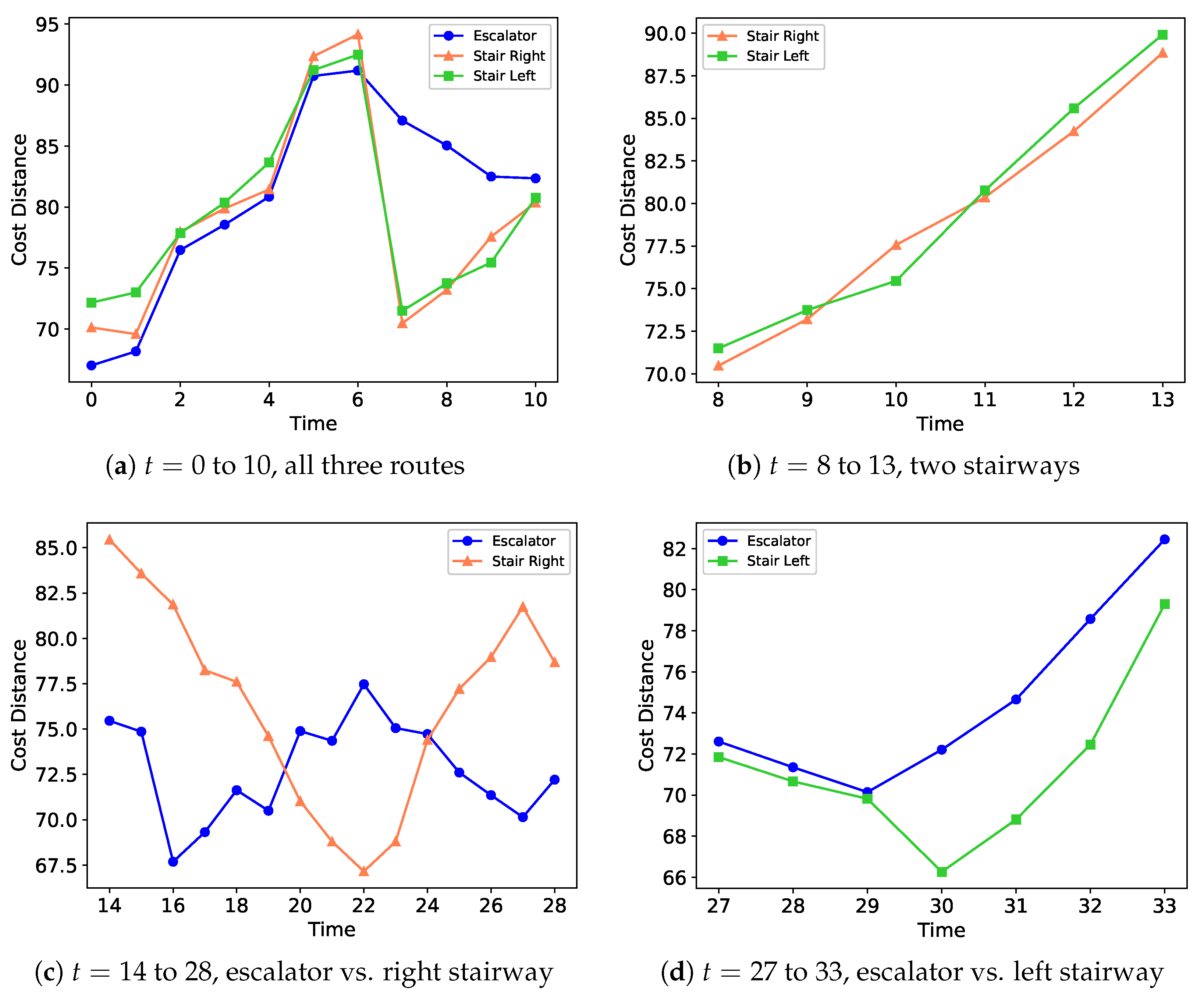
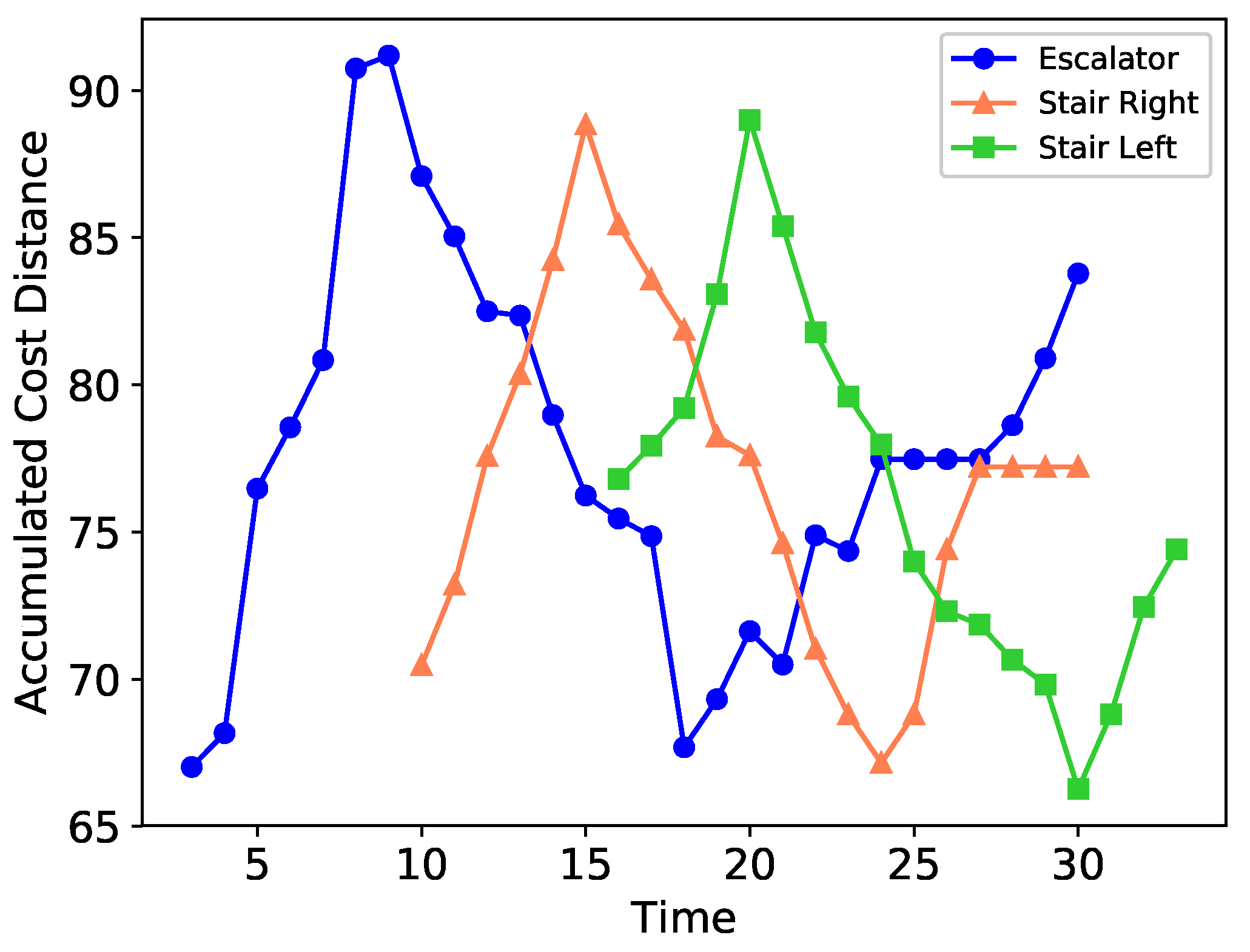
Figure 9 shows the cost comparison of available routes at different timestamps, and the cumulative costs of all three routes during the simulation are presented in
Figure 10. Similar to the previous example, when the first ant (at
) reaches the node, all three routes are available, but it selects the one with the lowest cost and enters the escalator. As the cost distance of the escalator route increases and reaches its
(at
), the system directs the following ants to select the two stairs until the accumulated cost of the escalator decreases back to its
. The cost comparison of the two stair routes (at
to 13) is shown in
Figure 9b, which the system uses to select which stair to go when the escalator was “closed” for passengers to enter during that period.
Similarly, the comparison between the escalator and the right stair as well as between the escalator and the left stair at different timestamps are displayed in
Figure 9c,d, respectively. The recorded accumulated costs shown in
Figure 10 suggest that after the escalator is full, the ants are directed to take the right stair route, as this stairway gives the least cost-distance. The accumulated cost of the right stair reaches its first
at
and is closed for passenger entry; meanwhile, its accumulated cost begins to decrease until the value drops to its
(at
). As the accumulated cost of the escalator does not decrease to its LCP, the left stairway starts to take traffic at
and reaches its
at
. The accumulated cost continues to decrease until it reaches its
at
. Additionally, the figure also indicates that the accumulated cost of the escalator is reduced to its
at
and allows the route to be “open” to access again. Although the passenger is allowed to select the escalator from this timestamp, the developed ACO system makes the accumulated cost of the left stair reach its
at
to 20 to yield the maximum use of the
.
It is also noticed that the accumulated costs of the escalator and the right stair converge at
. The system then directs the traffic to the escalator (as it had a lower cost) until
, after which the left stair starts to take the traffic again beginning at
. Compared to
Figure 8b,
Figure 10 suggests that increasing the number of route selections results in a more complex growth-and-decline pattern in terms of the accumulated costs. However, the developed ACO system can guide an ant in selecting the most appropriate route by considering both the cost distance and the accumulated cost at specific timestamps, ensuring the effective use of available
to operate the system properly.
Although the proposed ACO system dynamically adjusts the
and
to guide an ant, the time complexity mainly depends on the number of ants (
m) and the number of paths (
p). Take
Figure 2 for instance, the number of ants is 30 and the number of paths is 6. The time complexity to initialize the system is
O(
m+
p) because the fist ant does not have to track the pheromone density for route selection. During the subsequent search for the best route, the time complexity may reach
O(
mp) at worst when there are
p paths having certain amount of accumulated pheromone (running time =
O(
p)), so an ant spends more time determining the optimal path. However, this worst case can be mitigated after the accumulated pheromone on specific paths increases. Therefore, the time complexity of the proposed system falls between
O(
m+
p) and
O(
mp). One solution to reduce the time complexity is using several machines for parallel processing. For example, the time complexity can be reduced by a factor of 1/
m when exploiting
m machines, i.e., each ant is processed individually on a separate machine.
In the proposed ACO system, the cost of determining the best route varies dynamically according to the attributes and environmental impact factors of the site. The cost distance and accumulated cost play the role of controlling the in-and-out flow for the real-time solutions. The scenarios imitate the ants’ behavior in the real world by introducing a random cost into each candidate route, and suboptimal investigations are utilized to represent the consecutive routing procedures for the passengers. As a result, this simulated best route searching mechanism offers various aspects to determine routes according to time and cost variations. The examples presented above demonstrate that the proposed systematic framework enables flexible strategies and effective solutions to deal with emergency evacuation services in a complex environment.

