Article

Thermal Performance and Building Energy Simulation of Precast Insulation Walls in Two Climate Zones

1
College of Civil Engineering, Central South University, Changsha 410075, China
2
Engineering Technology Research Center for Prefabricated Construction Industrialization of Hunan Province, Changsha 410075, China
3
Audit Division, Central South University, Changsha 410083, China
*
Author to whom correspondence should be addressed.
Buildings 2024, 14(9), 2612; https://doi.org/10.3390/buildings14092612
Submission received: 30 July 2024 / Revised: 19 August 2024 / Accepted: 22 August 2024 / Published: 23 August 2024
(This article belongs to the Section Building Energy, Physics, Environment, and Systems)

Abstract

Traditional concrete buildings exhibit low energy consumption and high heat loss, which results in a larger environmental problem. Precast insulation walls are proposed for strengthening thermal insulation efficiency and mitigating heat loss. Numerous studies have investigated the thermal performance of insulation walls over the past decades. However, gaps remain in practical engineering applications. This study aims to bridge these gaps by providing practical design recommendations based on experimental research. Nine different types of precast insulation walls were tested to examine the thermal performance, and the parameters of the insulation material, insulation form, insulation layer thickness, and concrete rib width were investigated. Then, numerical models of these walls were developed for simulating the thermal performance of the tested specimens. Finally, a six-story student apartment model using designed walls was developed to assess energy consumption in two distinct climate zones: the hot summer and cold winter zone of Changsha City, and the cold zone of Harbin City. The results indicate that the precast insulation wall with external insulation form shows better thermal performance than the sandwich insulation form. It is recommended to use precast insulation walls with 50 mm extruded polystyrene (XPS) external thermal insulation form in Changsha City and 80 mm XPS external thermal insulation form in Harbin City. Furthermore, buildings using precast insulation walls can significantly reduce energy consumption by 49.25% in Changsha and 49.38% in Harbin compared to traditional concrete wall buildings. Based on these findings, suitable design suggestions for this precast concrete wall panel building composed of insulation walls are given.

1. Introduction

With the intensification of the global energy crisis and environmental issues, the importance of energy conservation, emission reduction, and sustainable development has become increasingly prominent [1,2,3,4,5]. Building energy consumption accounts for nearly 40% of global energy use, making it a key focus area for energy conservation efforts [6,7,8,9,10]. According to the “China Building Energy Consumption and Carbon Emissions Annual Report 2023 [11]”, building operational energy consumption continuously increased from 2010 to 2021, with an average annual growth rate of 5.3%. Residential buildings, being the largest type of building, require further attention to reduce their energy consumption. The core of residential building energy conservation lies in the renovation of building envelope and building heating systems [12,13,14]. The building envelope, as the primary area of energy consumption in buildings, will become the breakthrough point for solving the technical problems of building insulation and energy conservation [15]. According to relevant technical statistics, heat loss through wall structures makes up the majority of heat dissipation in various parts of the building envelope [14,16]. Therefore, improving the performance of residential building walls is of paramount importance for promoting sustainable development and reducing building energy consumption.
To improve the thermal performance of building walls and ensure structural safety. many scholars have embarked on research into the thermal and mechanical performance of precast insulation walls [17,18,19]. On the mechanical side, beyond the experimental investigation of the mechanical properties of connectors in sandwich walls [20,21,22,23], new wall types are proposed. These include the use of Steel Fiber Reinforced Self-Compacting Concrete [24], high-performance recycled aggregate concrete [25], Deflection Hardening Cement Composite (DHCC) materials, and GFRP skin [26] in wall panels. Experiments have been conducted to assess their bending and seismic performance. On the thermal side, current research primarily focuses on the materials and thermal performance of precast insulation walls [27,28]. Yu et al. [29] proposed an equivalent heat transfer coefficient model for precast concrete sandwich walls verified through experimental and numerical studies that proved suitable for walls with stainless steel connectors. Kim et al. [30] examined three types of mechanical connectors, finding that W-shape connectors had the lowest heat transfer rate. Zhai et al. [31] improved thermal performance by wrapping connectors with nylon, reducing material conductivities, increasing connector spacing and insulation thickness, and reducing rebar diameter. Bida et al. [32] designed staggered shear connectors to avoid thermal bridges, improving thermal resistance. O’Hegarty et al. [33] demonstrated that using vacuum insulation with non-metallic connectors results in superior thermal performance, although reduced panel thickness increases the impact of thermal bridging. While extensive experimental research has been conducted by the aforementioned scholars, current thermal studies primarily address connector aspects. Further exploration is needed in the areas of green building materials and lightweight components.
The impact of a building envelope on energy consumption has been examined by scholars through various energy consumption simulations. Sheng et al. [34] used DeST software to model a five-star hotel, analyzing its energy use across three climate zones and suggesting energy-saving renovations. Zhou et al. [35] employed TRNSYS software to quantify energy consumption for buildings with expanded polystyrene (EPS) exterior walls in five climate zones, optimizing insulation thickness. Liu et al. [36] utilized Design Builder software to rank the sensitivity of thermal design parameters for six building envelope structures, proposing recommended values. Ma et al. [37] used eQUEST software to study the impact of a building envelope on energy consumption in three types of public buildings in North China, offering energy-saving recommendations. Zhou et al. [38] analyzed four office buildings in different cities using DeST software, concluding that optimal building envelope structures should be based on actual usage and occupants. Nyme Uddin et al. [39] conducted simulations incorporating resident behavior to select sustainable building envelope materials suitable for the local context. Altun and Akan [40,41] used TRNSYS 18 and MATLAB R2019a software to study the influence of climate conditions on optimal building envelope parameters in various Turkish cities, considering both energy efficiency and economic viability. Atmaca et al. [42] employed Open Studio and Energy Plus programs to model and improve building envelope characteristics for mosques, focusing on thermal comfort and energy consumption.
Despite advances in understanding insulation walls’ thermal performance and building envelope design’s impact on energy use, gaps remain in practical engineering applications. Studies often isolate the thermal properties of specimens from overall energy performance. This paper integrates experimental research on insulation walls with broader energy consumption analysis, aiming to develop practical design recommendations that enhance wall structures’ thermal performance and reduce building energy use.
In response to the challenges mentioned above, Luo et al. [43] previously introduced a novel precast concrete composite wall connected by tooth groove and grouted sleeve. The feasibility and reliability of this novel connection method were verified, and the seismic behavior was explored through the low-cyclic reversed loading tests of two full-scale specimens. During test loading, the insulation layer of the precast insulation wall maintained excellent bonding performance with the concrete structure layer, demonstrating superior cooperative working performance. As a precast insulation wall integrating lightweight, load-bearing, and thermal insulation, it not only has good mechanical properties but also needs excellent thermal performance. This paper aims to further explore the thermal performance of such walls, determine the optimal design configurations for precast insulation walls, and apply these findings to practical engineering projects.
The behavior of thermal performance of precast insulation walls was explored through experimental and numerical analyses. Previous studies indicate that the insulation form, insulation material, and insulation layer thickness significantly influence thermal performance [17,31], with the concrete rib’s width also impacting thermal bridging and, consequently, the thermal performance of walls. This paper analyzes the effects of these factors on insulation walls and selects the most suitable design configurations for precast insulation walls for Changsha and Harbin City. Thermal performance is usually expressed in the building sector as thermal resistance or thermal transmittance [44,45,46]. To accurately characterize the thermal performance of precast insulation walls and apply it in energy consumption analysis models, thermal transmittance is used to represent the thermal performance of these walls. In addition, a six-story student apartment model was proposed using DeST-h 2.0 software to evaluate the building’s energy-saving effect by comparing the differences in building energy consumption between precast insulation wall buildings and precast concrete wall buildings. Finally, suitable design suggestions for this building composed of precast insulation walls were provided. It is hoped that the research results of this paper will encourage the widespread adoption and application of such buildings. The flowchart of this study is shown in Figure 1.

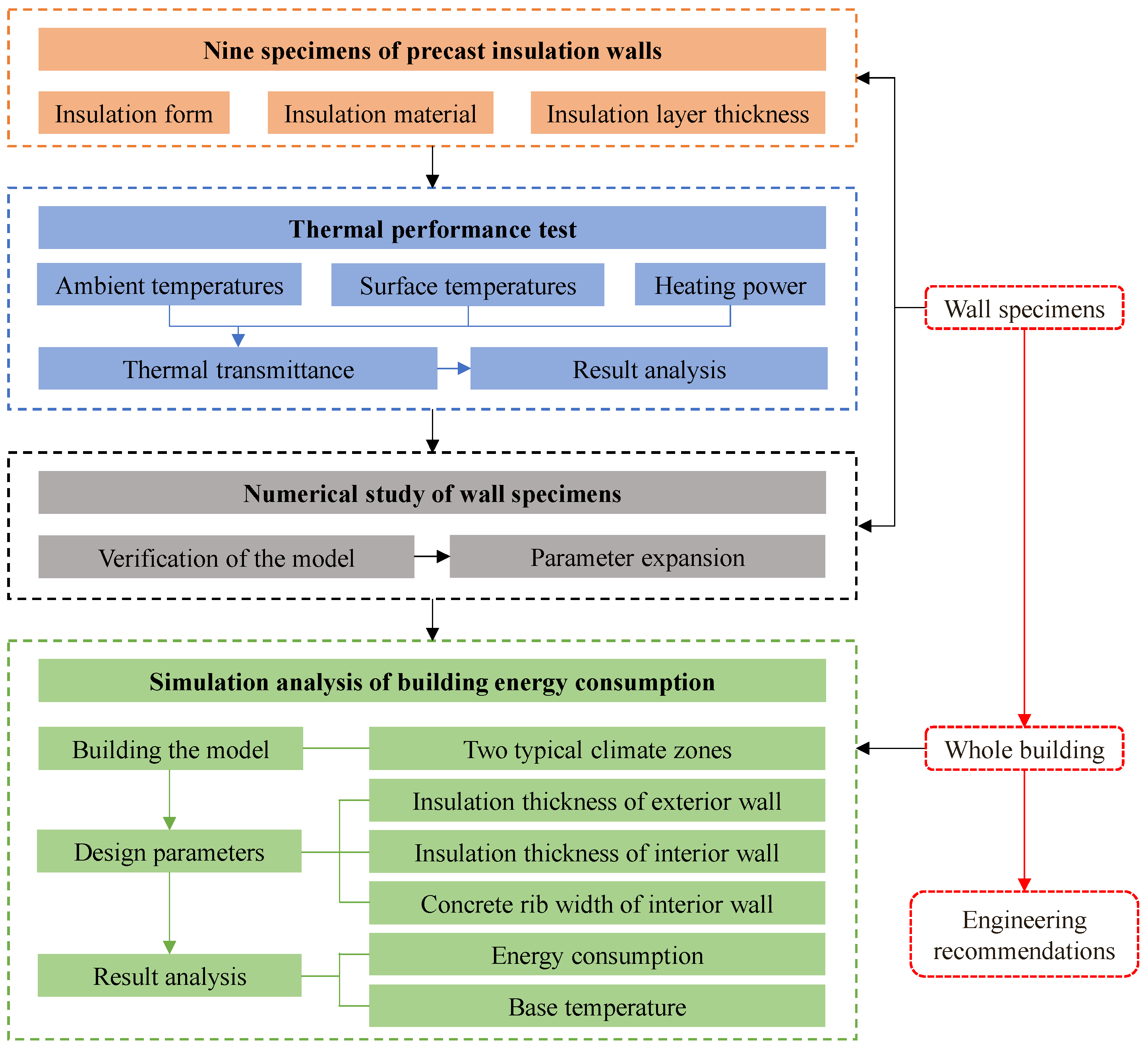
2. Experimental Investigation

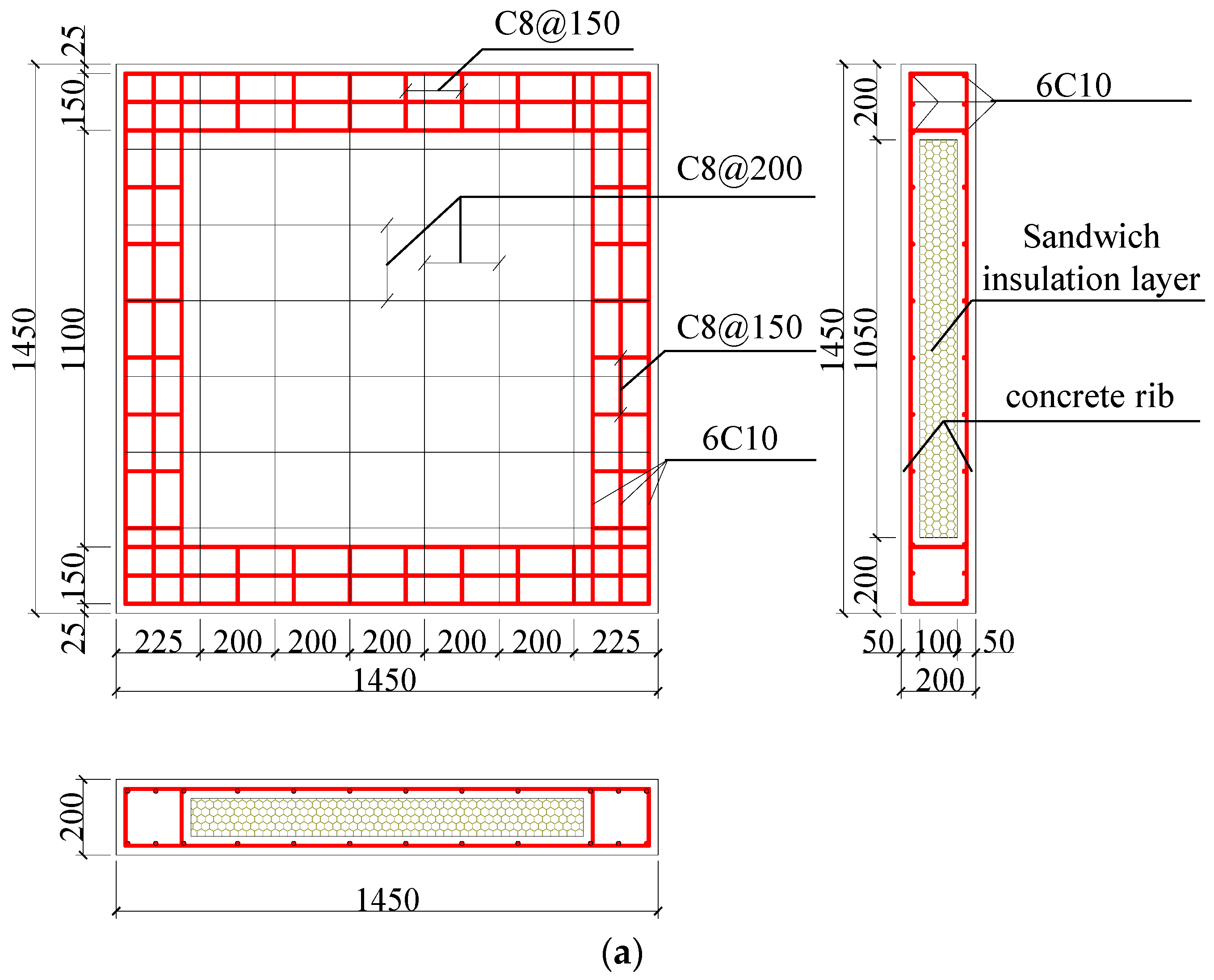
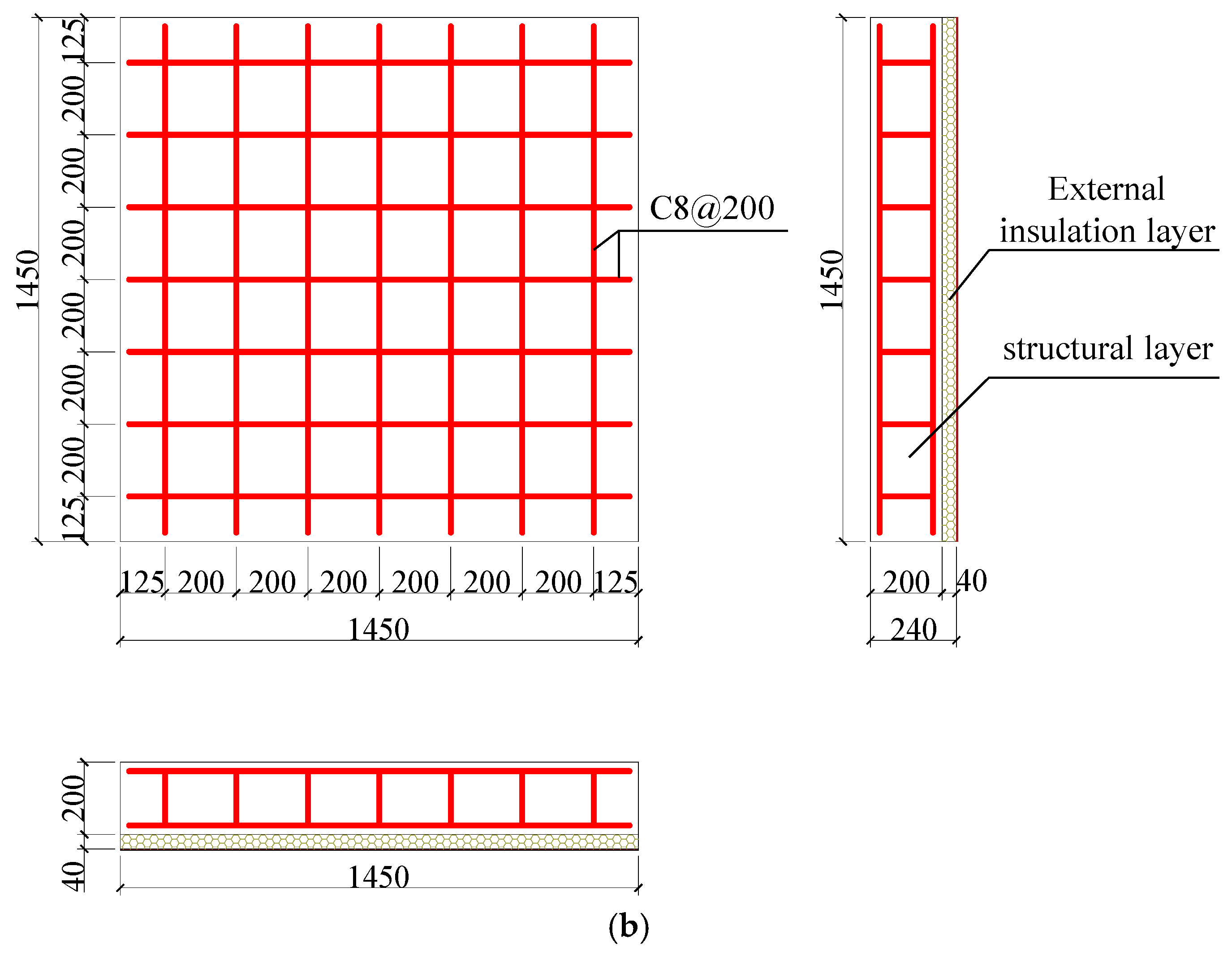
2.1. Specimen Design

Due to limitations in the test site conditions, the dimensions of the specimens are 1450 mm × 1450 mm, with their thickness determined by the insulation layer. The parameters of wall specimens are listed in Table 1. Three commonly used insulation materials were adopted for the insulation layer: extruded polystyrene (XPS), perlite foam concrete, and foamed concrete. Based on the different positions of the insulation layer, the insulation form can be divided into two types: external insulation and sandwich insulation. The specimens with external insulation consisted of concrete walls with insulation layers pasted on, with thicknesses of 40 mm and 80 mm, respectively. The reinforcement details of the external insulation wall specimens are shown in Figure 2a. The specimens with sandwich insulation featured a 100 mm insulation layer inside, which could be used as a template to form concealed columns and beams. The reinforcement details of the sandwich insulation wall specimens are shown in Figure 2b.

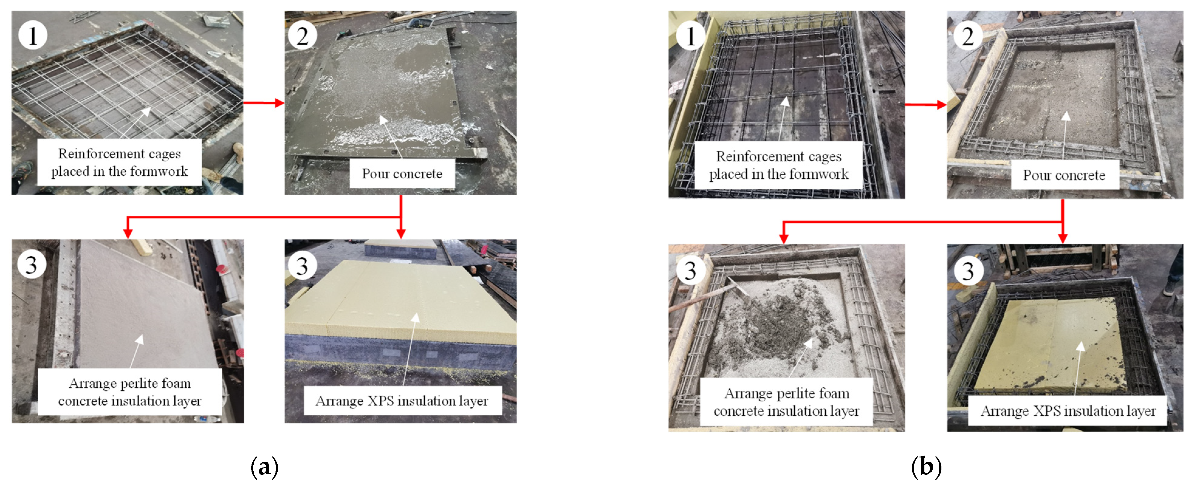
2.2. Construction Process

The precast insulation walls for testing were prefabricated in a factory setting. Firstly, the molds were assembled according to the design dimensions on a mold platform, ensuring all internal debris was cleared, and a release agent was sprayed. Secondly, the reinforcement cage for the structural layer was tied inside the mold, and once it was secured, concrete was poured and thoroughly vibrated to ensure proper compaction. After the concrete pouring and vibrating were completed, the insulation layer for insulation walls with foam concrete insulation and perlite foam concrete insulation was applied using physical foaming and perlite mortar pouring on the outer surface once the concrete had initially been set. For XPS insulation walls, the XPS boards were laid on the surface after the concrete for the structural layer had been poured and initially smoothed. The construction process of specimens is shown in Figure 3.

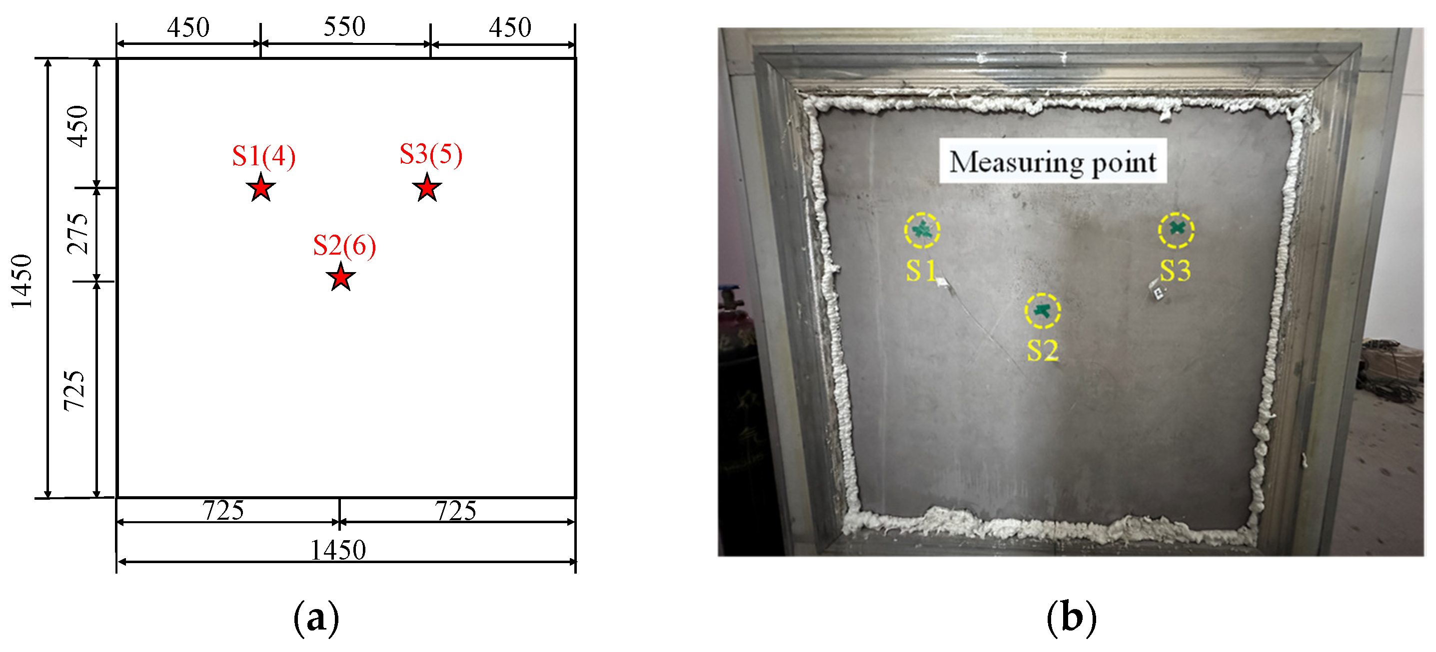
2.3. Experimental Setup

The calibrated hot box [47,48] was used to evaluate the thermal performance of each specimen, as illustrated in Figure 4. The hot side of the hot box was set to 20 °C and designated as the inner wall, while the cold side was set to −20 °C and designated as the outer wall. This configuration aimed to simulate the indoor and outdoor environments after winter heating. Due to compressor refrigeration issues, the cold box temperature for specimens TP-5, TP-6, TP-7, and TP-9 was adjusted to −15 °C, while the ambient temperature for other specimens remained unchanged. Each specimen was equipped with a total of three measurement points, with a temperature sensor (Type T thermocouple) placed on both the inner and outer sides at each point. The positive electrode of the type T thermocouple is made of pure copper, while the negative electrode is made of copper-nickel alloy. This type of thermocouple has high thermal electromotive force, good stability and uniformity, and high sensitivity, rendering it suitable for measuring low temperatures. The locations of thermocouples are depicted in Figure 5. Before the surface temperature reached stability, real-time monitoring and data recording were conducted, with data collected approximately every half hour on average. Prior to the experiment, it was necessary to seal the gaps between the specimen and the equipment using polyurethane foam adhesive to ensure proper filling and sealing. The hot box heater was adjusted to ensure that both sides of the test piece maintained stable air velocity, air temperature, and thermal radiation conditions during the test, while the ambient temperatures in the cold and hot boxes were kept constant using the thermal performance testing device. The experiment was concluded when the surface temperatures of the specimen reached near-steady-state conditions, the deviations of the measured surface temperatures and the calculated thermal resistance and thermal transmittance values on both sides of the specimen were less than 1% for at least 3 h, and the surface temperatures did not exhibit unidirectional changes each hour.

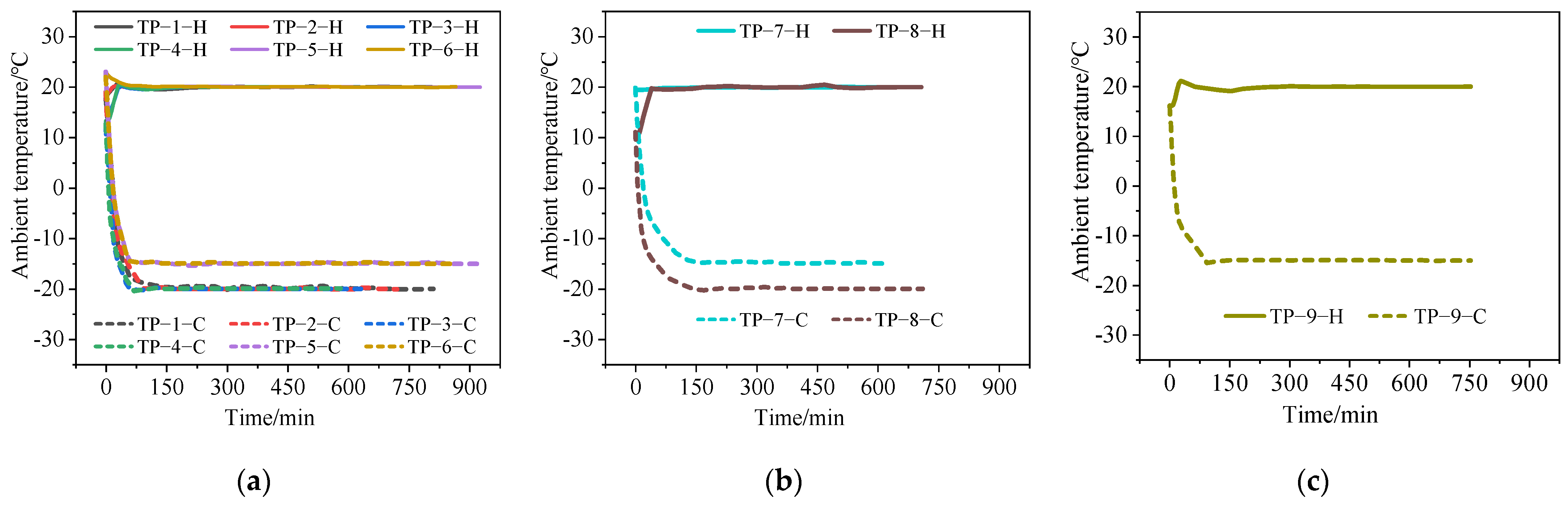
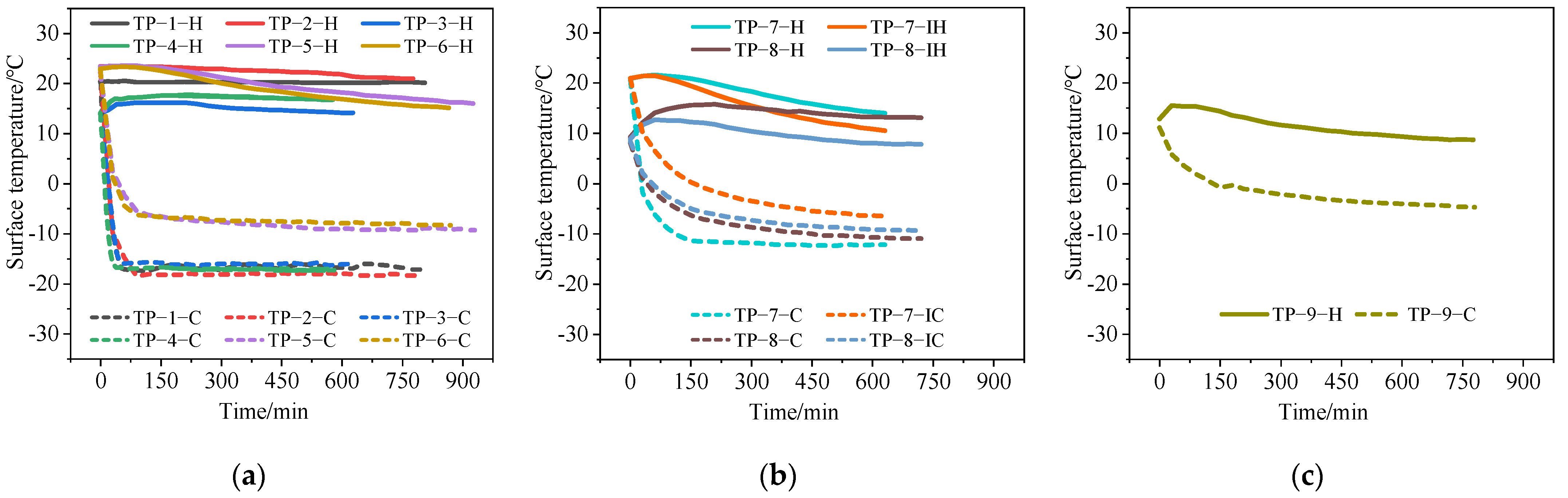
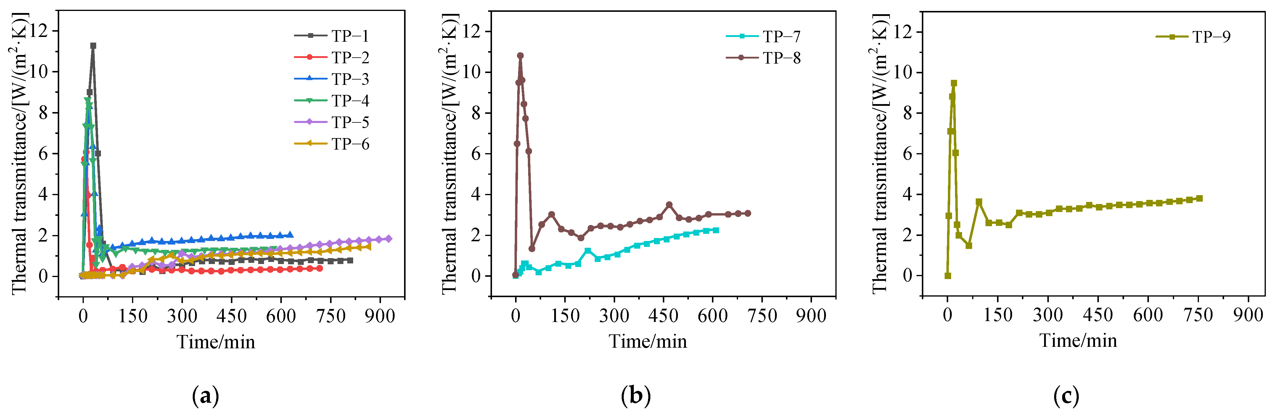
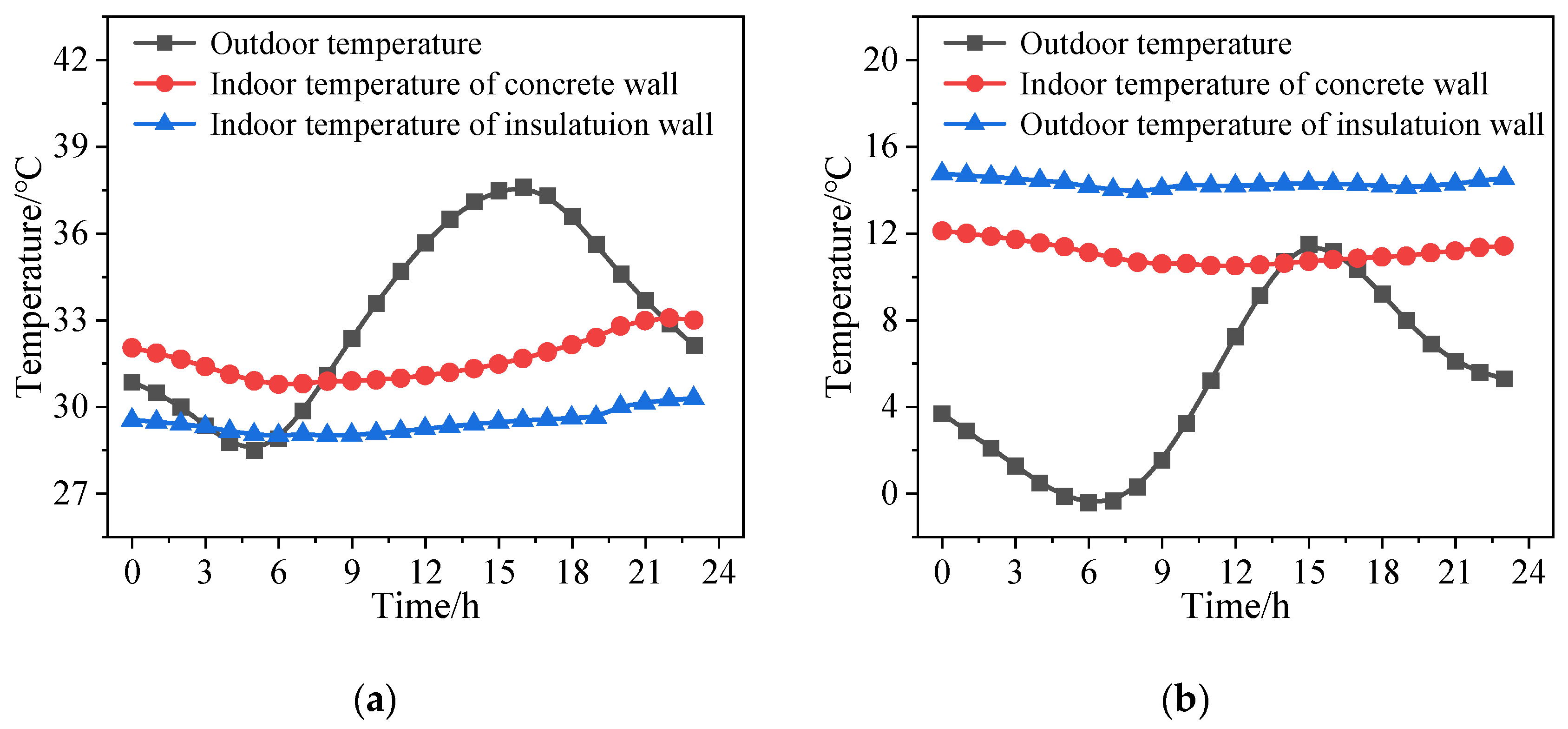
2.4. Experimental Results

Nine precast insulation walls were tested in this experiment. The ambient temperatures of hot and cold boxes, the average inner and outer surface temperatures, and the heater power were recorded, allowing for the calculation of the thermal transmittance of each specimen. The ambient temperature curves of hot and cold boxes and the average inner and outer surface temperature curves are shown in Figure 6 and Figure 7, where H represents the hot box or hot side, C represents the cold box or cold side, IH represents the hot side of the insulation layer, and IC represents the cold side of the insulation layer.
As noted in Figure 6, during the initial test stage, the ambient temperatures of the hot and cold boxes exhibited a monotonous increase and decrease, respectively, due to the heat transfer not yet reaching a steady state. Similarly, the surface temperature changes on the hot and cold sides exhibited the same pattern during the initial test stage, as shown in Figure 7. From Figure 8, it is seen that since the initial temperatures of specimens TP-1, TP-2, TP-3, TP-4, TP-8, and TP-9 were below 20 °C; the heater needed to start at a high heating power to raise the temperature in the hot box. In contrast, the initial temperatures of specimens TP-5, TP-6, and TP-7 were above 20 °C, so the heater did not require a high heating power at the beginning. Heat transfer reached a steady state after approximately 150 min, with ambient temperatures, surface temperatures, and heating power subsequently stabilizing. To ensure accuracy, over three hours of data were recorded after the heat transfer had stabilized before concluding the thermal performance test.
The thermal transmittance K of the specimen is calculated from the power consumed by the heater in the hot box. The calculation formula is as follows:
K = Q M 1 Δ θ 1 M 2 Δ θ 2 A Δ t
where Q represents the electrical power consumed by the heater; M1 represents the heat flux coefficient of the outer wall of the hot box and can be determined as 3.11 W/K; M2 represents the heat flux coefficient of the specimen frame and can be determined as 0.32 W/K; Δθ1 represents the temperature difference of the inner and outer surfaces of the hot box outer wall; Δθ2 represents the temperature difference of the cold and hot sides of the specimen frame; A represents area of the wall specimen; and Δt represents the difference between the average temperatures of the cold and hot box air.
As depicted in Figure 9, after obtaining the thermal parameters of specimens TP-1 to TP-9 at steady state, the values were substituted into Equation (1) to calculate their thermal transmittances, and experimental results are provided in Table 2.
As shown in Table 2, it was observed that both the external insulation and the sandwich insulation forms of the precast insulation walls reduced the thermal transmittance of the wall compared to specimen TP-9. However, for the sandwich wall, the presence of concrete ribs led to a significant thermal bridge effect, resulting in a notable difference in thermal performance compared to the external insulation wall. Among the external insulation walls, those using externally attached XPS boards demonstrated the relatively best thermal performance, while those using externally attached foamed concrete exhibited the poorest thermal performance. Additionally, the insulation layer thickness had a significant impact on the insulation effect of the wall. The specimens having an insulation layer thickness of 80 mm showed a much greater improvement in thermal performance compared to those with a thickness of 40 mm.
The external attachment of XPS boards demonstrated the best insulation performance among the precast insulation walls tested. However, the board is prone to detachment, potentially impacting the building use functions and life span. Conversely, the external attachment of perlite foam concrete exhibited poorer insulation performance, but it synergizes better with concrete, providing certain strength and ensuring a longer service life for the building. Meanwhile, the sandwich insulation walls showed lower thermal performance compared to the external insulation walls; nevertheless, the insulation material inside can significantly reduce the weight of the wall, enabling lightweight construction. Therefore, the choice of insulation material and form should be made based on specific requirements and considerations.

3. Numerical Simulation

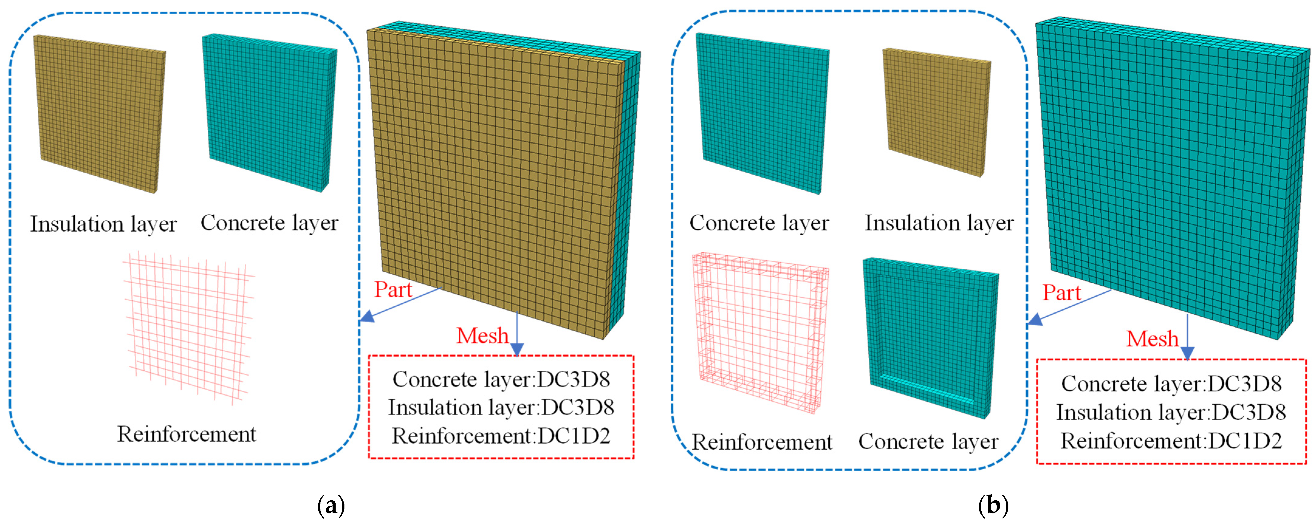
3.1. Tested Wall Model

In this section, the finite element (FE) software ABAQUS 2022 was utilized to perform the heat transfer analysis on precast insulation walls. Numerical models of nine precast insulation walls were established and validated against experimental results. Following this, the FE model was employed for parameter analysis.

3.1.1. Basic Principles of Heat Transfer in Building Envelope

Under the influence of temperature differences between the interior and exterior of buildings, heat is transferred through wall materials via conduction [49], convection [50], and radiation [51,52], thereby affecting the energy efficiency and indoor comfort of buildings [53]. The effects of thermal radiation and convection are collectively reflected in the surface coefficient of heat transfer provided in the GB 50176-2016 [54]. It is necessary to take into account the combined effects of thermal radiation and convection when designing thermal insulation for buildings.

3.1.2. Interactions and Boundary Conditions

Due to the neglect of thermal contact resistance in the analysis process and the close contact between concrete and reinforcement bars, tie connections were applied between concrete and insulation materials, as well as between concrete and reinforcement bars, to ensure that the temperatures at corresponding points on these interfaces remained consistent. Two physical constants required for heat transfer analysis were set in the model properties: absolute zero temperature was set to −273.15 °C, and the Stefan-Boltzmann constant was set to 5.76 × 10⁻⁸ W/(m2·K4). According to the GB 50176-2016 [54], the thermal transmittances for the inner and outer surfaces in the FE model were set to 8.7 W/(m2 °C) and 23 W/(m2 °C), respectively. The indoor and outdoor temperatures were consistent with the experimental settings, with the indoor temperature set to 20 °C and the outdoor temperature set to −20 °C or −15 °C. The comprehensive radiation coefficient between the surface of the specimen and the surrounding air temperature was set at 0.7. The initial temperature of the precast insulation walls was set at 10 °C. The FE modeling process is indicated in Figure 10.

3.1.3. Basic Assumptions

To simplify the heat transfer analysis, several assumptions were made in the FE model, as follows:
(1)
Neglecting the thermal contact resistance caused by interface gaps during construction in the simulation analysis. It is assumed that the temperature and heat flux on both sides of the contact surface are continuous.
(2)
Simplification to a steady-state heat transfer problem. In practical engineering applications, the indoor temperature of the insulated wall remains relatively constant, while the outdoor temperature fluctuates significantly due to environmental influences. In the simulation process, the temperature on both sides of the wall is maintained under the most unfavorable conditions, ensuring the maximum constant temperature difference. Under these conditions, heat always flows from indoors to outdoors.
(3)
All materials are considered isotropic, with unchanged thermal properties. Their values are given in Table 3.

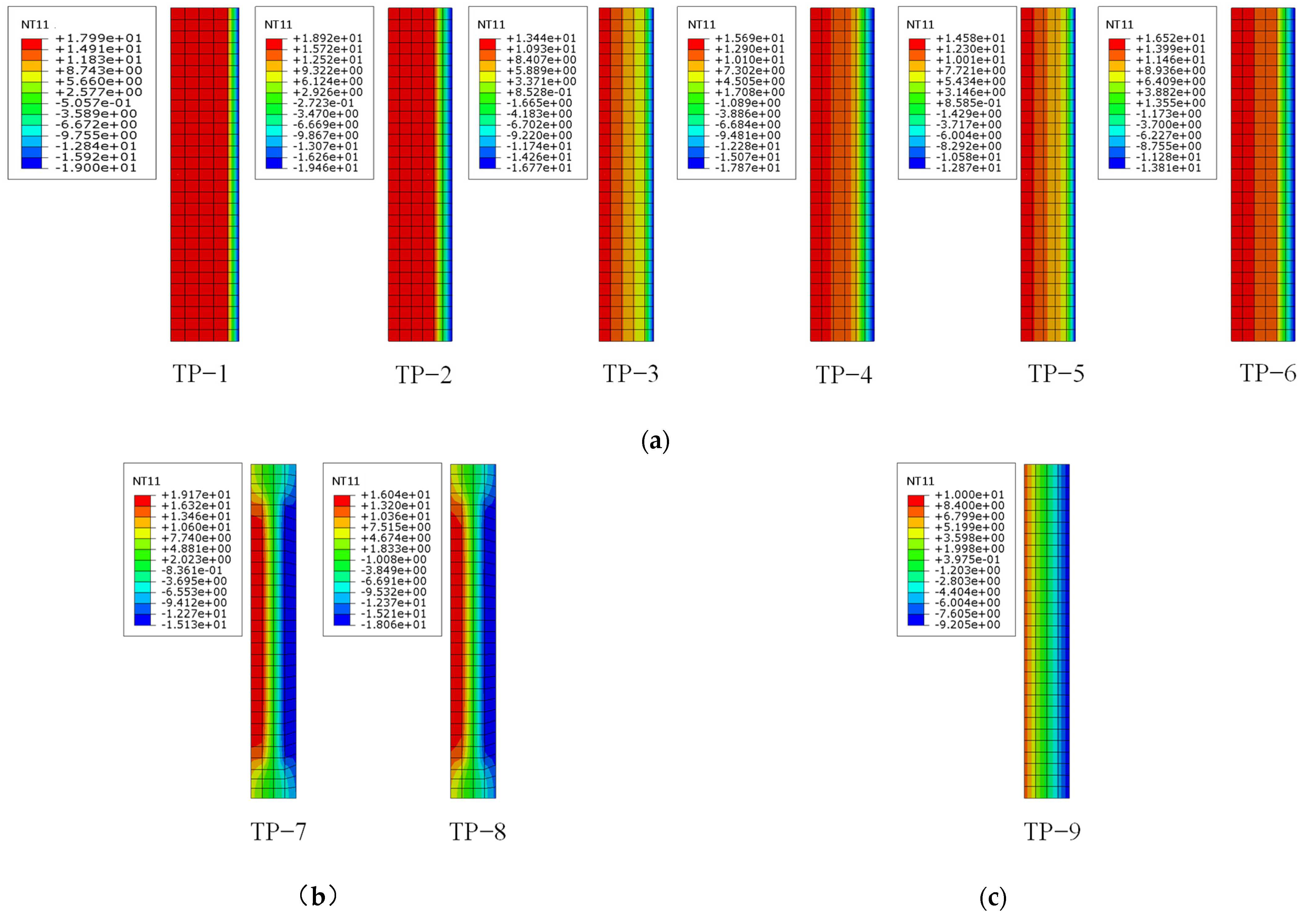
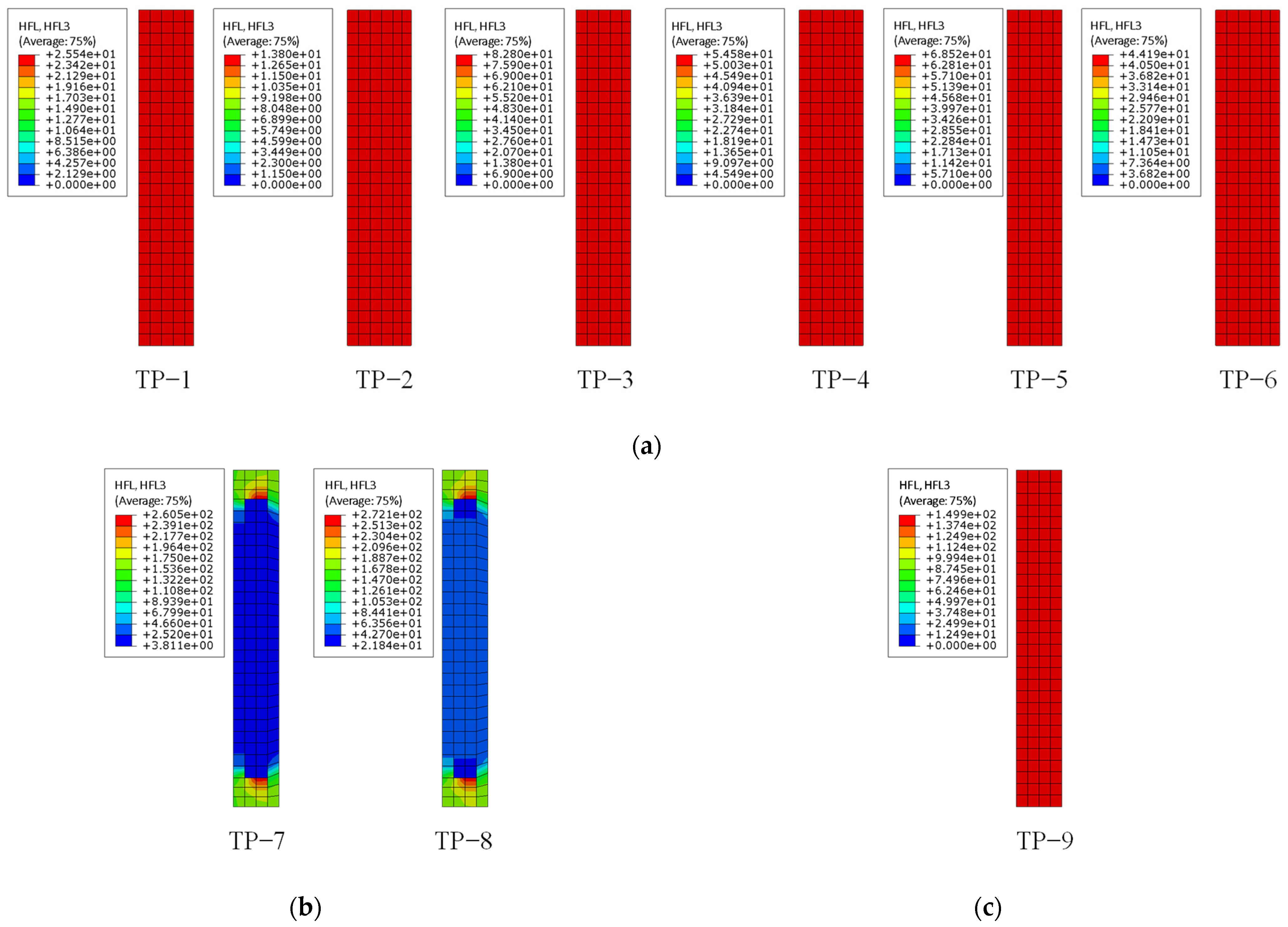
3.2. Validation of the Tested Wall Model

Thermal performance simulations for specimens TP-1 to TP-9 were conducted using ABAQUS 2022. Upon reaching steady-state conditions, temperature distributions of the specimens were obtained, as shown in Figure 11. Visualization results from the FE analysis allowed the extraction of heat flux density distributions in three directions. However, since the calibration hot box method employed in this study is based on the basic assumption of “one-dimensional heat transfer”, only the heat flux density contour plot (HFL3) along the thickness direction of the inner surface of the specimen was investigated, as depicted in Figure 12. Comparison of the numerical temperature and heat flux distributions of specimens TP-1 to TP-6 reveals patterns consistent with the experimental results mentioned above. The thermal performance of the exterior insulation walls using externally attached XPS boards is superior to those using externally attached perlite foam concrete or foamed concrete. Additionally, the thickness of the insulation layer significantly affects the thermal performance of the wall. From the numerical temperature and heat flux distributions of specimens TP-7 and TP-8, it was observed that there is still a relatively significant thermal bridge effect in the sandwich insulation specimen. The surface temperature distribution of the specimen is uneven, with faster heat transfer speeds and denser heat flux in the concrete rib area, while the sandwich insulation area with internal XPS board filling exhibits relatively slower heat transfer speeds. Overall, the thermal performance of the exterior insulation specimens is significantly higher than that of the sandwich insulation specimens.
Based on the research by Lee et al. [55], the FE numerical results can be used to calculate the thermal transmittance according to Equation (2):
K = q T a h T a c
where q represents heat flux, which is calculated by averaging the heat fluxes of all the elements on the surface of the inner wall, Tah represents air temperatures with the inner wall side, and Tac represents air temperatures with the outer wall side.
The numerical values are compared with the experimental values, and uncertainty metrics are calculated, including Mean Bias Error (MBE), Normalized Mean Bias Error (NMBE), Coefficient of Variation of the Root Mean Square Error (CV(RMSE)), and coefficient of determination (R2) [56]. As shown in Table 4 and Table 5, the thermal transmittance results from FE analyses closely align with the experimental data for the nine walls. MBE, NMBE, CV(RMSE), and R2 all fall within the allowable error range, indicating minimal deviation and high model accuracy. The negative values of MBE and NMBE suggest a slight overestimation of the predictions. Therefore, the FE models are validated as reasonable through these comparisons and can be utilized for parametric analysis in the following sections.

3.3. Parametric Analysis

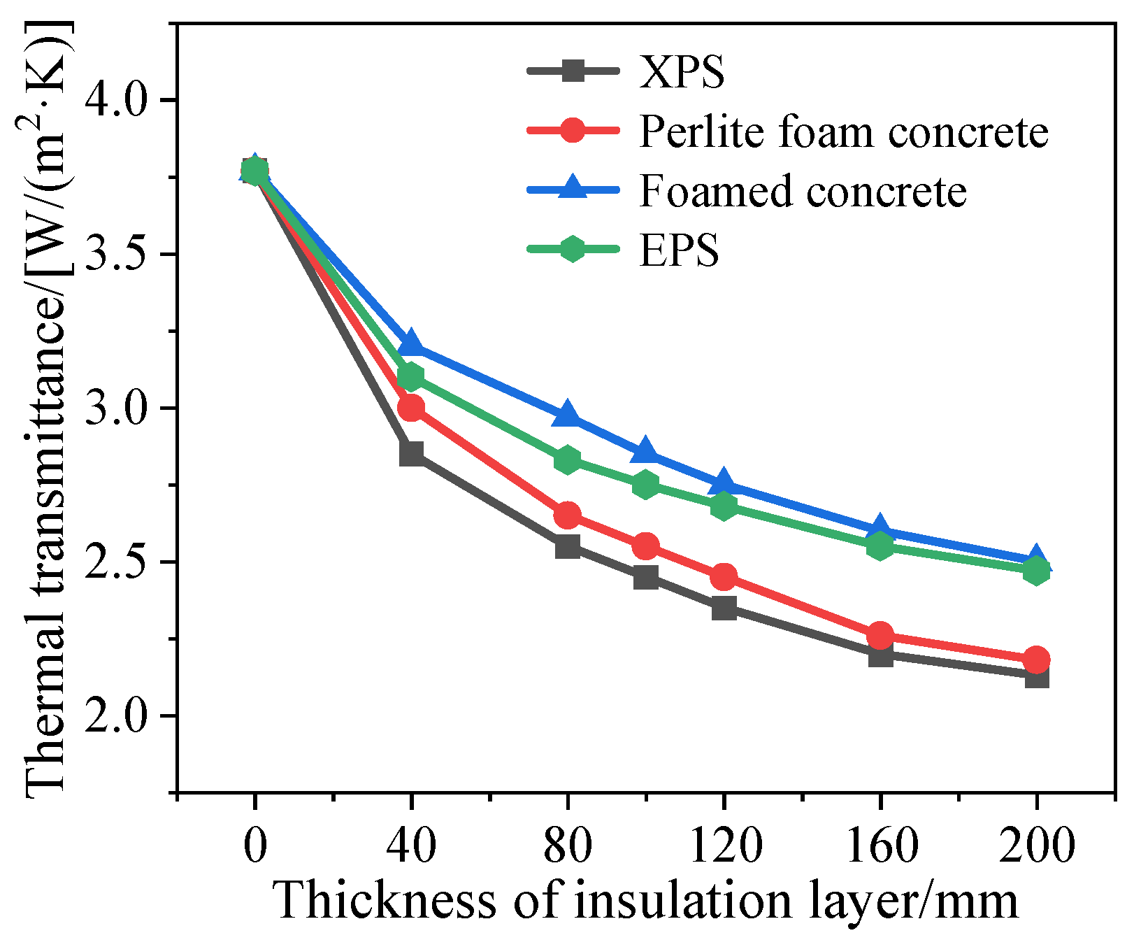
3.3.1. Insulation Layer Thickness and Material

Based on the experimental results, it is clear that the insulation layer thickness significantly influences the thermal performance of the wall. For external insulation form, the insulation thicknesses tested ranged from 0 to 100 mm, in 20 mm increments. The thermal transmittances of the four kinds of insulation materials are compared in Figure 13. It can be observed that as the insulation layer thickness increases, the thermal transmittance gradually decreases. Furthermore, with the increase in the insulation layer thickness, the reduction in the thermal transfer coefficient of the wall gradually diminishes. Moreover, variations in thermal transmittance exist depending on the type of insulation material. Under the same insulation layer thickness, the order of performance of the four insulation materials is as follows: XPS > EPS > foamed concrete > perlite foam concrete.
For sandwich insulation form, keeping the width of the concrete ribs at 150 mm, the thermal transmittances of the walls with four types of insulation materials at varying insulation layer thicknesses are compared and analyzed in Figure 14. Combined with Figure 13 and Figure 14, it is observed that as the insulation layer thickness increases, the thermal transmittance of the wall gradually decreases. However, the thermal performance of sandwich insulation walls is relatively weaker compared to external insulation. The internal filling insulation layer cannot significantly reduce the thermal bridge effect of reinforced concrete. It is commonly used for reducing the load of load-bearing walls and for inside wall insulation. Further research is needed for the application and promotion of sandwich insulation walls in building exterior walls.

3.3.2. Concrete Rib Width

Reinforced concrete has a relatively high thermal conductivity, which easily leads to thermal bridge effects, thereby diminishing the thermal performance of sandwich walls. In order to meet the load-bearing capacity of the wall while maintaining a certain level of thermal performance, the thermal transmittance of sandwich walls filled with 100 mm XPS board was compared under different widths of concrete rib width in Figure 15. It is observed that as the dimensions of the concealed columns increase, the thermal transmittance of the wall proportionally rises, following a roughly linear trend. This trend is attributed to the augmented volume of concrete, leading to a more pronounced disparity in surface temperature distribution across the wall. Consequently, this exacerbates thermal bridge effects, thereby impacting the overall thermal performance of the wall.

4. Building Energy Analysis

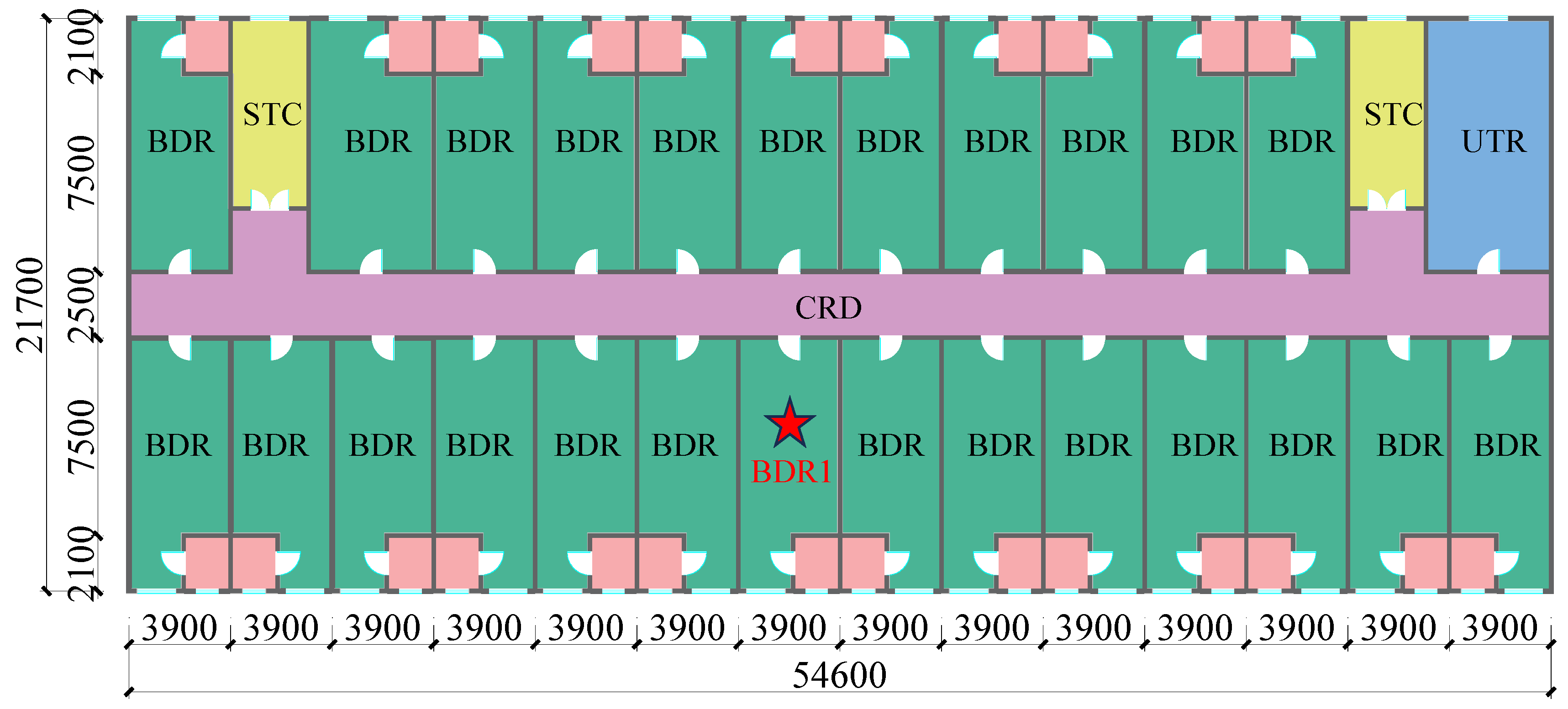
4.1. Prototype Model Overview

The software DeST-h 2.0 [57,58] was utilized to analyze the building energy consumption of a typical six-story apartment building featuring precast insulation walls. The annual energy consumption of the residential building was calculated under varying interior and exterior wall conditions. The layout plane of the building is depicted in Figure 16. The key structural parameters are as follows: the floor heights are 3 m, the length is 54.6 m, and the width is 21.7 m. No-energy-consuming space encompasses the bathroom (BTR), utility room (UTR), staircase (STC), and corridor (CRD), while energy-consuming space is attributed to the bedrooms (BDR).
The thermal disturbances within buildings can be broadly categorized into three types: occupant heat, lighting heat, and equipment heat. The thermal disturbance parameters for each room vary based on the actual usage of the building, and these parameters are detailed in Table 6. For the Changsha and Harbin areas, heating, cooling, and ventilation parameters were set according to their respective regional energy efficiency standards. In Changsha, the parameters followed the specification requirements of JGJ 134-2010 [59] and DBJ43/T025-2022 [60]. In Harbin, they conformed to the JGJ 26-2018 [61] and DB23/1270-2019 [62]. For both areas, a constant internal design temperature of 18 °C in winter and 26 °C in summer was maintained. The heating period in Changsha spans from 1 December to 28 February, with the cooling period extending from 15 June to 31 August. Additionally, in Harbin, heating spans from 10 October to 28 April, with cooling occurring between 1 July and 31 July. The rated energy efficiency ratio is 1.9 for heating and 2.3 for cooling in both areas. The air change rate was set at 1.0 time per hour for Changsha and 0.5 time per hour for Harbin during both heating and cooling periods.
The thermal conductivity, density, and specific heat capacity were defined for materials, and the main envelope constructions used in the building project are shown in Table 7. Based on experimental results and numerical parameter analysis, it is evident that XPS exhibits excellent thermal performance. Consequently, XPS boards were used as the insulation layer material for both interior and exterior walls in the energy consumption analysis. Exterior walls were constructed using external insulation, while interior walls were constructed using sandwich insulation. Except for exterior and interior walls, the materials for the remaining building envelope were set using default parameters in the program.

4.2. Result Analysis

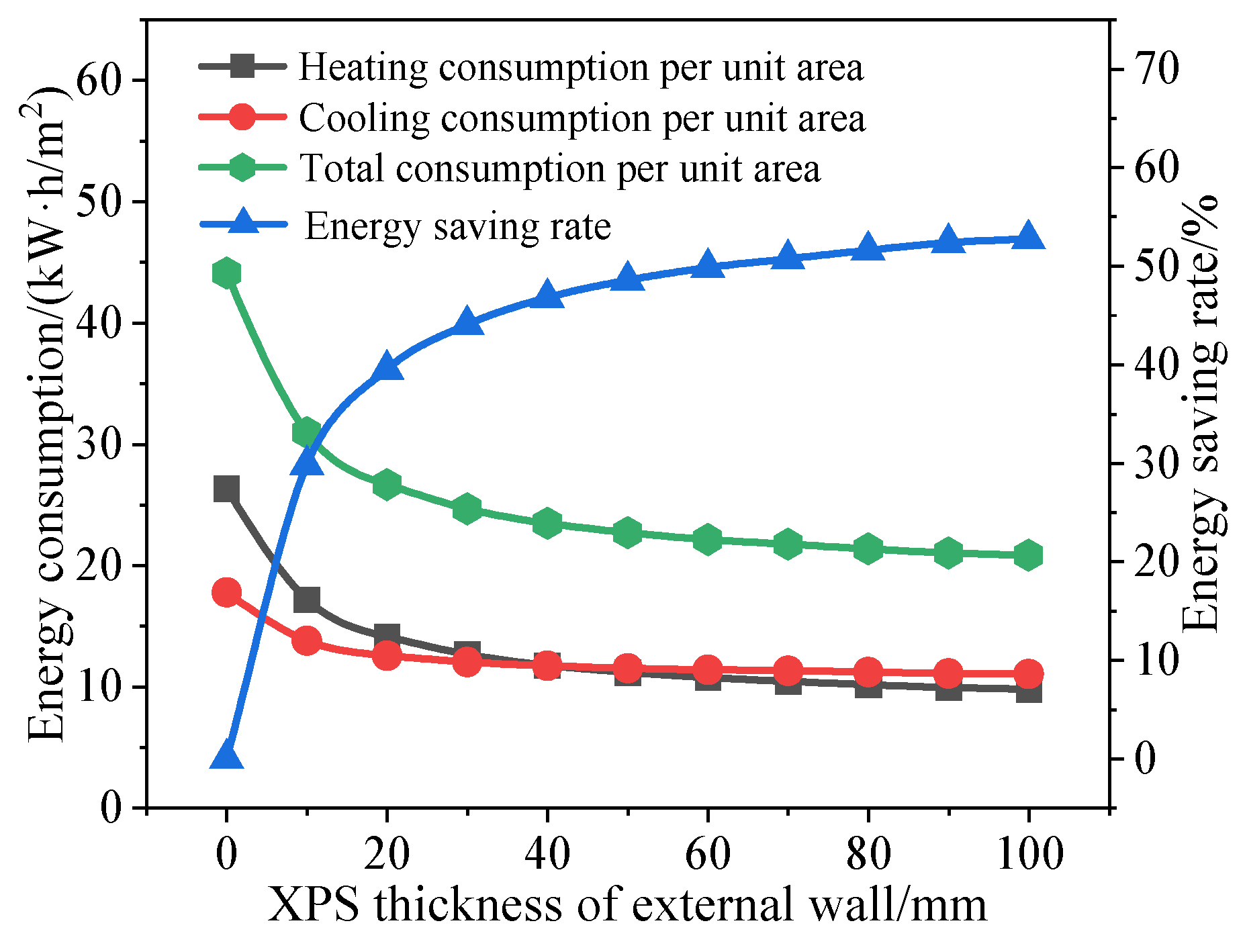
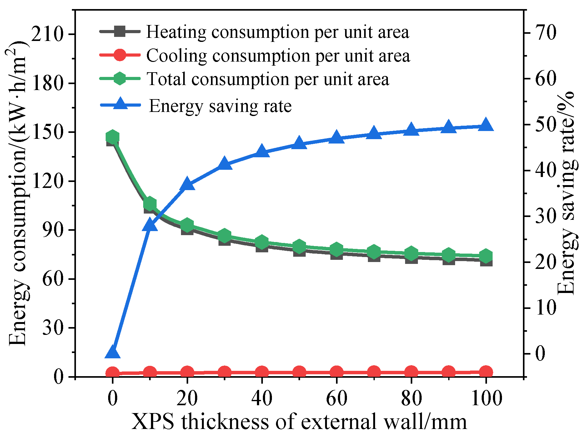
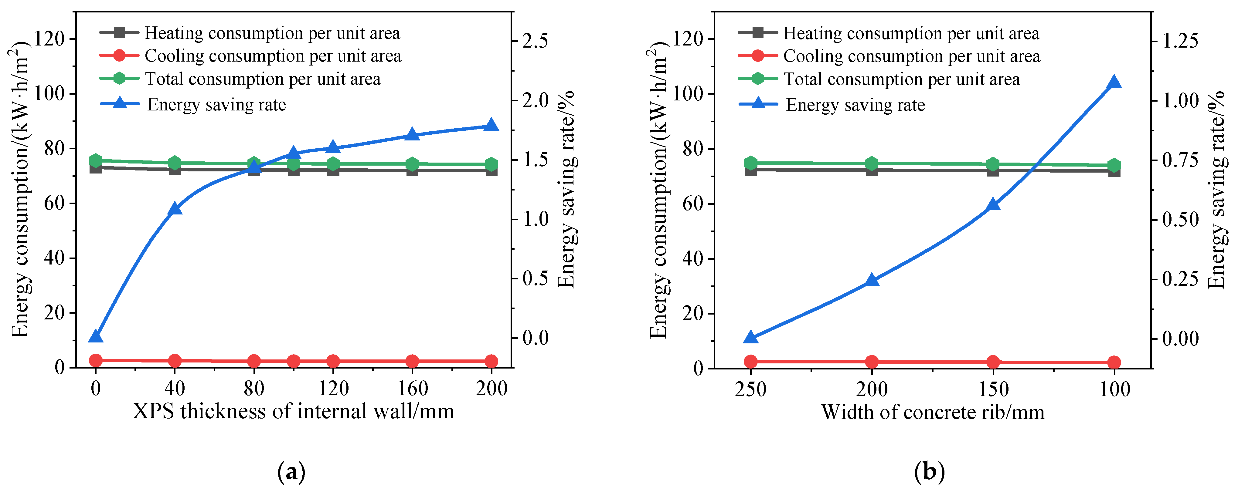
4.2.1. Energy Consumption

In the Changsha analysis, depicted in Figure 17, the increase in insulation layer thickness correlates with a gradual decrease in both heating and cooling consumption per unit area. The reduction in heating consumption per unit area is significantly greater than that in cooling consumption per unit area. During the building energy consumption simulation, varying the thickness of the XPS insulation layer from 0 mm to 100 mm yields a 52.76% decrease in total building energy consumption per unit area. Therefore, the increase in thickness of the XPS insulation layer on the exterior wall significantly reduces the building energy consumption. However, as insulation layer thickness increases, the reduction diminishes gradually. Hence, it is not advisable to set the XPS layer too thick. Notably, at a 50 mm insulation layer thickness, total building consumption per unit area diminishes by 48.55%. Balancing economic and energy-saving factors, the exterior walls of the student apartment are ideally outfitted with a 50 mm thick XPS insulation layer.
Figure 18a reveals a mere 2.11% decrease in total building consumption per unit area when varying the thickness of the interior wall XPS layer from 0 mm to 200 mm. Likewise, Figure 18b indicates that altering the width of the interior wall ribs from 250 mm to 100 mm only reduces total consumption per unit area by 1.91%. Therefore, for this apartment, changes in the interior wall XPS insulation layer thickness and the rib width have a minimal impact on the overall building energy consumption. The primary purpose of using sandwich insulation for interior walls is weight reduction. Considering structural weight reduction, mechanical performance of the walls, and economic indicators, the interior wall XPS insulation layer thickness should ideally be 100 mm, with a rib width of 150 mm for this apartment.
An analysis was conducted for Harbin, which, unlike Changsha, has a climate where the building consumption is primarily heating consumption, with cooling consumption being almost negligible. As shown in Figure 19, in the energy consumption simulation, the total consumption per unit area of the building decreases by 49.63% as the XPS insulation thickness varies from 0 mm to 100 mm. When the insulation thickness is 80 mm, the total consumption per unit area decreases by 48.59%. Considering both economic and energy-saving factors, it is recommended that the exterior walls of this student apartment be insulated with an 80 mm thick XPS layer.
Varying the thickness of the XPS insulation layer on the interior walls from 0 mm to 200 mm yields a modest 1.79% decrease in total consumption per unit area, as depicted in Figure 20a. Similarly, adjusting the width of the interior wall edge ribs from 250 mm to 100 mm, as illustrated in Figure 20b, results in a marginal 1.07% decrease in total consumption per unit area. Based on considerations of structural weight reduction, wall mechanical performance, and economic factors, it is recommended to set the thickness of the XPS insulation layer on interior walls at 100 mm and the width of the edge ribs at 150 mm for this apartment building.
In the Changsha area, when the exterior walls are constructed using external insulation with a 50 mm thick XPS layer and the interior walls are constructed using sandwich insulation with a 100 mm thick XPS layer, with a rib width of 150 mm, compared to both exterior and interior walls being of traditional concrete walls, the total building energy consumption decreases by 49.25%. Similarly, in the Harbin area, using 80 mm thick XPS external insulation for exterior walls and 100 mm thick XPS sandwich insulation for interior walls with a rib width of 150 mm reduces total building energy consumption by 49.38% compared to traditional concrete walls. This indicates that precast insulation wall construction, due to the external insulation layer, minimizes heat exchange between indoor and outdoor air, resulting in a significant reduction in residential building energy consumption. It exhibits superior thermal performance compared to traditional concrete wall construction.

4.2.2. Base Temperature

The base temperature represents the ambient temperature within a room, influenced by diverse meteorological factors, in the absence of heating or cooling systems. To precisely evaluate the insulation efficacy post-implementation of insulation walls, we scrutinized the fluctuation in base temperature within the first-floor BDR1 of the structure. A comparison of the winter and summer design day temperatures was conducted.
15 January was chosen to simulate the winter design day, while 1 August was chosen for the summer design day simulation. The indoor and outdoor temperature distributions of BDR1 on the first floor of this student apartment building under natural conditions during winter and summer design days are illustrated in Figure 21 and Figure 22. It is evident that during the summer design day in Changsha, the base temperature in the BDR1 with insulation wall construction is 2 °C to 4 °C lower than that with traditional wall construction. Conversely, during the winter design day, the base temperature in the BDR1 with insulation wall construction increases by approximately 3 °C compared to that with traditional wall construction. In Harbin, the base temperature in the BDR1 with insulation wall is 0.4 °C to 2 °C lower than that with concrete walls during summer design day. During winter design day, the base temperature in the BDR1 with insulation wall is approximately 10 °C higher compared to that with concrete walls. The temperature curves throughout the day for both insulation wall and traditional wall constructions indicate that the base temperature in the insulation wall construction remains relatively stable, significantly enhancing the room’s comfort level. Thus, the thermal performance of insulation wall construction markedly surpasses that of traditional wall construction.

5. Conclusions

In this paper, a precast insulation wall integrating lightweight, load-bearing, and thermal insulation was proposed for two typical climate zones. The thermal performance and energy consumption of these buildings were explored by experiment research and FE analysis. The conclusions are as follows:
  • The specimen with external insulation form can prevent the thermal bridge effect caused by reinforced concrete, thereby achieving superior thermal performance, making them suitable for building exterior walls. On the other hand, the sandwich insulation wall filled with insulation materials inside the specimen can achieve the building goal of lightweight components, which can be used for the building interior walls to reduce weight.
  • For the same thickness of the insulation layer, the thermal performance of the four insulation materials ranks as follows: XPS > EPS > foam concrete > perlite foam concrete. With the increase of the thickness of the insulation layer, the thermal performance of the precast insulation wall is gradually improved. However, the reduction in the thermal transfer coefficient of the wall gradually diminishes.
  • From the perspective of building energy consumption, increasing the thickness of the insulation layer on the exterior walls significantly reduces the building energy consumption. In contrast, changing the insulation layer thickness and the concrete rib width of the interior walls has minimal impact on energy consumption. Considering the climatic characteristics of different cities, it is recommended to use 50 mm thick XPS external insulation walls in Changsha and 80 mm thick XPS external insulation walls in Harbin. For interior walls, a 100 mm thick XPS insulation layer with 150 mm wide concrete ribs is recommended.
  • Compared with traditional concrete wall buildings, precast insulation wall buildings can significantly reduce building energy consumption by 49.25% in Changsha and 49.38% in Harbin. This indicates that insulation wall construction significantly improves the thermal performance of residential buildings.
  • The conclusions of this study not only provide a foundational basis for the engineering applications of such buildings but also offer a methodological reference for research on other types of insulation walls. However, this study has limitations; it only examines two climate zones in energy consumption simulations and does not consider the impact of occupant behavior and other relevant parameters on optimal wall design. Future research should expand the scope to include more working conditions.

Author Contributions

Conceptualization, X.L.; methodology, Y.H.; software, D.X.; validation, Q.C. and Y.B.; formal analysis, D.X. and Y.H.; investigation, Y.B.; resources, X.L. and Y.B.; data curation, D.X.; writing—original draft preparation, D.X. and Y.H.; writing—review and editing, Q.C. and D.X.; visualization, D.X.; supervision, X.L.; project administration, X.L.; funding acquisition, X.L. and Y.B. All authors have read and agreed to the published version of the manuscript.

Funding

The research was funded by the National Natural Science Foundation of China (Grant No. 52178179), the Hunan Science and Technology Plan Project (Grant No. 2023SK2014), and the Fundamental Research Funds for the Central Universities of Central South University (Grant No. 2023ZZTS0372).

Data Availability Statement

Data are contained within the article.

Conflicts of Interest

The authors declare no conflicts of interest.

References

  1. Wang, S.; Luo, Y.; Liu, Z.; Lu, B. Analysis on Energy Conservation and Emission Reduction Efficiency and Influencing Factors for Ports around Bohai in China under the Low Carbon Target. Sustainability 2022, 14, 14765. [Google Scholar] [CrossRef]
  2. Rathore, P.K.S.; Gupta, N.K.; Yadav, D.; Shukla, S.K.; Kaul, S. Thermal performance of the building envelope integrated with phase change material for thermal energy storage: An updated review. Sustain. Cities Soc. 2022, 79, 103690. [Google Scholar] [CrossRef]
  3. Lee, C.T.; Hashim, H.; Ho, C.S.; Fan, Y.V.; Klemeš, J.J. Sustaining the low-carbon emission development in Asia and beyond: Sustainable energy, water, transportation and low-carbon emission technology. J. Clean. Prod. 2017, 146, 1–13. [Google Scholar] [CrossRef]
  4. Kotov, E.V.; Nemova, D.; Sergeev, V.; Dontsova, A.; Koriakovtseva, T.; Andreeva, D. Thermal Performance Assessment of Aerogel Application in Additive Construction of Energy-Efficient Buildings. Sustainability 2024, 16, 2398. [Google Scholar] [CrossRef]
  5. Han, S.; Yao, R.; Li, N. The development of energy conservation policy of buildings in China: A comprehensive review and analysis. J. Build. Eng. 2021, 38, 102229. [Google Scholar] [CrossRef]
  6. de Rubeis, T.; Ciccozzi, A.; Giusti, L.; Ambrosini, D. The 3D Printing Potential for Heat Flow Optimization: Influence of Block Geometries on Heat Transfer Processes. Sustainability 2022, 14, 15830. [Google Scholar] [CrossRef]
  7. Hou, Q.; Xu, W.; Zhang, Z.; Wang, Y.; Zhang, H.; Tao, J. Research on the Optimisation of Dual-Heat-Source Heating Systems in Nearly Zero-Energy Buildings. Sustainability 2024, 16, 4516. [Google Scholar] [CrossRef]
  8. Huang, H.; Wang, H.; Hu, Y.-J.; Li, C.; Wang, X. The development trends of existing building energy conservation and emission reduction—A comprehensive review. Energy Rep. 2022, 8, 13170–13188. [Google Scholar] [CrossRef]
  9. Kang, Y.; Xu, W.; Wu, J.; Li, H.; Liu, R.; Lu, S.; Rong, X.; Xu, X.; Pang, F. Study on comprehensive whole life carbon emission reduction potential and economic feasibility impact based on progressive energy-saving targets: A typical renovated ultra-low energy office. J. Build. Eng. 2022, 58, 105029. [Google Scholar] [CrossRef]
  10. Zhong, Z.; Zhang, X.; Yang, X. Benefit evaluation of energy-saving and emission reduction in construction industry based on rough set theory. Ecol. Chem. Eng. S 2021, 28, 61–73. [Google Scholar] [CrossRef]
  11. Efficiency, C.A.o.B.E. China Building Energy Consumption and Carbon Emissions Annual Report 2023. Constr. Archit. 2024, 2, 46–59. [Google Scholar]
  12. Cao, X.; Dai, X.; Liu, J. Building energy-consumption status worldwide and the state-of-the-art technologies for zero-energy buildings during the past decade. Energy Build. 2016, 128, 198–213. [Google Scholar] [CrossRef]
  13. Jelle, B.P. Traditional, state-of-the-art and future thermal building insulation materials and solutions—Properties, requirements and possibilities. Energy Build. 2011, 43, 2549–2563. [Google Scholar] [CrossRef]
  14. Sadineni, S.B.; Madala, S.; Boehm, R.F. Passive building energy savings: A review of building envelope components. Renew. Sustain. Energ. Rev. 2011, 15, 3617–3631. [Google Scholar] [CrossRef]
  15. Kumar, D.; Alam, M.; Memon, R.A.; Bhayo, B.A. A critical review for formulation and conceptualization of an ideal building envelope and novel sustainability framework for building applications. Clean. Eng. Technol. 2022, 11, 100555. [Google Scholar] [CrossRef]
  16. Nardi, I.; Lucchi, E.; de Rubeis, T.; Ambrosini, D. Quantification of heat energy losses through the building envelope: A state-of-the-art analysis with critical and comprehensive review on infrared thermography. Build. Environ. 2018, 146, 190–205. [Google Scholar] [CrossRef]
  17. Tawil, H.; Tan, C.G.; Sulong, N.H.R.; Nazri, F.M.; Sherif, M.M.; El-Shafie, A. Mechanical and Thermal Properties of Composite Precast Concrete Sandwich Panels: A Review. Buildings 2022, 12, 1429. [Google Scholar] [CrossRef]
  18. Mugahed Amran, Y.H.; El-Zeadani, M.; Huei Lee, Y.; Yong Lee, Y.; Murali, G.; Feduik, R. Design innovation, efficiency and applications of structural insulated panels: A review. Structures 2020, 27, 1358–1379. [Google Scholar] [CrossRef]
  19. Kermani, A. Performance of structural insulated panels. Proc. Inst. Civ. Eng. Struct. Build. 2006, 159, 13–19. [Google Scholar] [CrossRef]
  20. Xue, W.; Fu, K.; Li, X. Accelerated aging tests for evaluation of shear behavior of FRP connectors in precast sandwich insulation wall panels. Build. Struct. 2012, 42, 106–108+118. [Google Scholar]
  21. Xue, W.; Fu, K.; Qin, H. Accelerated aging tests of tensile strength of FRP connectors in precast concrete sandwich wall panels. J. Build. Mater. 2014, 17, 420–424. [Google Scholar]
  22. Xue, W.; Yang, J.; Wang, J. Pull-out tests for evaluations of anti-pulling behavior of FRP connectors in precast sandwich insulation wall panels. Fiber Reinf. Plast. Compos. 2012, 4, 55–59. [Google Scholar]
  23. Yang, J.; Xue, W.; Li, X. Mechanical properties test of FRP connectors in precast sandwich insulation wall panels. J. Jiangsu Univ. (Nat. Sci. Ed.) 2013, 34, 723–729. [Google Scholar]
  24. Lameiras, R.; Barros, J.A.O.; Valente, I.B.; Poletti, E.; Azevedo, M.; Azenha, M. Seismic behaviour of precast sandwich wall panels of steel fibre reinforced concrete layers and fibre reinforced polymer connectors. Eng. Struct. 2021, 237, 112149. [Google Scholar] [CrossRef]
  25. Lipczynska, J.; West, R.P.; Grimes, M.; Niall, D.; Kinnane, O.; O’Hegarty, R. Composite behaviour of wide sandwich panels with thin high performance recycled aggregate concrete wythes with fibre reinforced polymer shear connectors. J. Struct. Integr. Maint. 2021, 6, 187–196. [Google Scholar] [CrossRef]
  26. Mastali, M.; Valente, I.B.; Barros, J.A. Flexural performance of innovative hybrid sandwich panels with special focus on the shear connection behavior. Compos. Struct. 2017, 160, 100–117. [Google Scholar] [CrossRef]
  27. Aditya, L.; Mahlia, T.M.I.; Rismanchi, B.; Ng, H.M.; Hasan, M.H.; Metselaar, H.S.C.; Muraza, O.; Aditiya, H.B. A review on insulation materials for energy conservation in buildings. Renew. Sustain. Energ. Rev. 2017, 73, 1352–1365. [Google Scholar] [CrossRef]
  28. Dong, X.; Lu, Y.; Xiao, H.; Liao, J. Effects of various connectors on the whole-life-cycle energy consumption of sandwich wall panels in five thermal zones of China. Energy Build. 2023, 280, 112733. [Google Scholar] [CrossRef]
  29. Yu, S.; Liu, Y.; Wang, D.; Ma, C.; Liu, J. Theoretical, experimental and numerical study on the influence of connectors on the thermal performance of precast concrete sandwich walls. J. Build. Eng. 2022, 57, 104886. [Google Scholar] [CrossRef]
  30. Kim, Y.J.; Allard, A. Thermal response of precast concrete sandwich walls with various steel connectors for architectural buildings in cold regions. Energy Build. 2014, 80, 137–148. [Google Scholar] [CrossRef]
  31. Zhai, X.; Wang, Y.; Wang, X. Thermal performance of precast concrete sandwich walls with a novel hybrid connector. Energy Build. 2018, 166, 109–121. [Google Scholar] [CrossRef]
  32. Bida, S.M.; Abdul Aziz, F.N.A.; Jaafar, M.S.; Hejazi, F.; Abu Bakar, N. Thermal Resistance of Insulated Precast Concrete Sandwich Panels. Int. J. Concr. Struct. Mater. 2021, 15, 41. [Google Scholar] [CrossRef]
  33. O’Hegarty, R.; Reilly, A.; West, R.; Kinnane, O. Thermal investigation of thin precast concrete sandwich panels. J. Build. Eng. 2020, 27, 100937. [Google Scholar] [CrossRef]
  34. Sheng, Y.; Miao, Z.; Zhang, J.; Lin, X.; Ma, H. Energy consumption model and energy benchmarks of five-star hotels in China. Energy Build. 2018, 165, 286–292. [Google Scholar] [CrossRef]
  35. Zhou, S.; Zhao, J. Optimum combinations of building envelop energy-saving technologies for office buildings in different climatic regions of China. Energy Build. 2013, 57, 103–109. [Google Scholar] [CrossRef]
  36. Liu, Y.; Zou, S.; Chen, H.; Wu, X.; Chen, W. Simulation Analysis and Scheme Optimization of Energy Consumption in Public Buildings. Adv. Civ. Eng. 2019, 2019, 6326138. [Google Scholar] [CrossRef]
  37. Ma, H.; Du, N.; Yu, S.; Lu, W.; Zhang, Z.; Deng, N.; Li, C. Analysis of typical public building energy consumption in northern China. Energy Build. 2017, 136, 139–150. [Google Scholar] [CrossRef]
  38. Zhou, X.; Yan, D.; An, J.; Hong, T.; Shi, X.; Jin, X. Comparative study of air-conditioning energy use of four office buildings in China and USA. Energy Build. 2018, 169, 344–352. [Google Scholar] [CrossRef]
  39. Nyme Uddin, M.; Jahan Ruva, I.; Abu Syed, M.; Hossain, D.; Akter, R.; Tamanna, N.; Rahman, A.; Saka, A. Occupant centric energy renovation strategy for hospital and restaurant building envelop using distinct modellingtools: A case study from low-income cultural context. Energy Build. 2022, 272, 112338. [Google Scholar] [CrossRef]
  40. Akan, A.E. Determination and Modeling of Optimum Insulation Thickness for Thermal Insulation of Buildings in All City Centers of Turkey. Int. J. Thermophys. 2021, 42, 49. [Google Scholar] [CrossRef]
  41. Altun, A.F. Determination of Optimum Building Envelope Parameters of a Room concerning Window-to-Wall Ratio, Orientation, Insulation Thickness and Window Type. Buildings 2022, 12, 383. [Google Scholar] [CrossRef]
  42. Atmaca, A.B.; Zorer Gedik, G.; Wagner, A. Determination of Optimum Envelope of Religious Buildings in Terms of Thermal Comfort and Energy Consumption: Mosque Cases. Energies 2021, 14, 6597. [Google Scholar] [CrossRef]
  43. Luo, X.; Chen, Q.; Deng, C.; Luo, W.; He, Y. Low-Cyclic Reversed Loading Tests on Full-Scale Precast Concrete Composite Wall Connected by Tooth Groove and Grouted Sleeve. Materials 2024, 17, 476. [Google Scholar] [CrossRef] [PubMed]
  44. Evangelisti, L.; Scorza, A.; De Lieto Vollaro, R.; Sciuto, S.A. Comparison between Heat Flow Meter (HFM) and Thermometric (THM) Method for Building Wall Thermal Characterization: Latest Advances and Critical Review. Sustainability 2022, 14, 693. [Google Scholar]
  45. Evangelisti, L.; Barbaro, L.; De Cristo, E.; Guattari, C.; D’Orazio, T. Towards an improved thermometric method: Convective and radiative heat transfer for heat flux measurement through an indirect approach. Therm. Sci. Eng. Prog. 2024, 49, 102479. [Google Scholar]
  46. Bienvenido-Huertas, D. Assessing the Environmental Impact of Thermal Transmittance Tests Performed in Façades of Existing Buildings: The Case of Spain. Sustainability 2020, 12, 6247. [Google Scholar] [CrossRef]
  47. Asdrubali, F.; Baldinelli, G. Thermal transmittance measurements with the hot box method: Calibration, experimental procedures, and uncertainty analyses of three different approaches. Energy Build. 2011, 43, 1618–1626. [Google Scholar]
  48. Shen, Z.; Brooks, A.L.; He, Y.; Shrestha, S.S.; Zhou, H. Evaluating dynamic thermal performance of building envelope components using small-scale calibrated hot box tests. Energy Build. 2021, 251, 111342. [Google Scholar]
  49. Wang, Y.; Wu, X.; Yang, X.; Owens, G.; Xu, H. Reversing heat conduction loss: Extracting energy from bulk water to enhance solar steam generation. Nano Energy 2020, 78, 105269. [Google Scholar] [CrossRef]
  50. Fang, R.; He, Y.; Li, Z.; Lu, H.; Zhao, Y. Analysis on heat flux delay effect of track slab temperature model in high temperature season. J. East China Jiaotong Univ. 2022, 39, 31–36. [Google Scholar]
  51. Hao, H.; Li, J.; Zhang, T.; Ruan, W. Design of ka-band linear tapered slot antennas based on substrate integrated waveguide feed. J. Electron. Inf. Technol. 2020, 42, 582–588. [Google Scholar]
  52. Zhang, S.; Zhu, N.; Lv, S. Human response and productivity in hot environments with directed thermal radiation. Build. Environ. 2021, 187, 107408. [Google Scholar] [CrossRef]
  53. Ellzey, J.L.; Belmont, E.L.; Smith, C.H. Heat recirculating reactors: Fundamental research and applications. Prog. Energy Combust. Sci. 2019, 72, 32–58. [Google Scholar] [CrossRef]
  54. GB 50176-2016; Code for Thermal Design of Civil Building. China Architecture & Building Press: Beijing, China, 2016.
  55. Lee, B.-J.; Pessiki, S. Thermal behavior of precast prestressed concrete three-wythe sandwich wall panels. In Building Integration Solutions; ASCE Press: Reston, VA, USA, 2006; pp. 1–15. [Google Scholar]
  56. Ruiz, G.; Bandera, C. Validation of Calibrated Energy Models: Common Errors. Energies 2017, 10, 1587. [Google Scholar] [CrossRef]
  57. Sun, H.; Leng, M. Analysis on building energy performance of Tibetan traditional dwelling in cold rural area of Gannan. Energy Build. 2015, 96, 251–260. [Google Scholar] [CrossRef]
  58. Yan, D.; Xia, J.; Tang, W.; Song, F.; Zhang, X.; Jiang, Y. DeST—An integrated building simulation toolkit Part I: Fundamentals. Build. Simul. 2008, 1, 95–110. [Google Scholar] [CrossRef]
  59. JGJ 134-2010; Design Standard for Energy Efficiency of Residential Buildings in Hot Summer and Cold Winter Zone. Ministry of Housing and Urban-Rural Development of the People’s Republic of China: Beijing, China, 2010.
  60. DBJ43/T025-2022; Design Standard for Energy Efficiency of Residential Buildings in Hunan Province. Department of Housing and Urban-Rural Development of Hunan Province: Changsha, China, 2022.
  61. JGJ 26-2018; Design Standard for Energy Efficiency of Residential Buildings in Severe Cold and Cold Zones. Ministry of Housing and Urban-Rural Development of the People’s Republic of China: Beijing, China, 2018.
  62. DB23/1270-2019; Design Standard for Energy Efficiency of Residential Buildings in Heilongjiang Province. Department of Housing and Urban-Rural Development of Heilongjiang: Harbin, China, 2019.
Figure 1. Flowchart of the study.
Buildings 14 02612 g001
Figure 2. The reinforcement details of the specimens (unit: mm): (a) Specimen with sandwich insulation; (b) Specimen with external insulation.
Buildings 14 02612 g002aBuildings 14 02612 g002b
Figure 3. Construction process of specimens: (a) External insulation walls; (b) Sandwich insulation walls.
Buildings 14 02612 g003
Figure 4. Schematic diagram of calibrated hot box. Note: Φp represents total input power of the electric heater; Φ1 represents heat flow through the specimen; Φ3 represents heat flow through the walls of the metering box; Φ4 represents heat flow bypassing the sides of the specimen.
Buildings 14 02612 g004
Figure 5. Location of measuring points:(a) Schematic diagram; (b) Experimental diagram.
Buildings 14 02612 g005
Figure 6. Measured ambient temperatures: (a) External insulation walls; (b) Sandwich insulation walls; (c) No insulation wall.
Buildings 14 02612 g006
Figure 7. Measured surface temperatures: (a) External insulation walls; (b) Sandwich insulation walls; (c) No insulation wall.
Buildings 14 02612 g007
Figure 8. Heating power: (a) External insulation walls; (b) Sandwich insulation walls; (c) No insulation wall.
Buildings 14 02612 g008
Figure 9. Thermal transmittance of specimens: (a) External insulation walls; (b) Sandwich insulation walls; (c) No insulation wall.
Buildings 14 02612 g009
Figure 10. FE modeling process: (a) External insulation walls; (b) Sandwich insulation walls.
Buildings 14 02612 g010
Figure 11. Numerical temperature distributions: (a) External insulation walls; (b) Sandwich insulation walls; (c) No insulation wall.
Buildings 14 02612 g011
Figure 12. Numerical heat flux distributions: (a) External insulation walls; (b) Sandwich insulation walls; (c) No insulation wall.
Buildings 14 02612 g012
Figure 13. Thermal transmittance versus insulation layer thickness curves (external insulation).
Buildings 14 02612 g013
Figure 14. Thermal transmittance versus insulation layer thickness curves (Sandwich Insulation).
Buildings 14 02612 g014
Figure 15. Thermal transmittance versus concrete rib width.
Buildings 14 02612 g015
Figure 16. Layout plane of the building.
Buildings 14 02612 g016
Figure 17. Relationship of exterior wall parameters and building energy consumption and saving rate in Changsha area.
Buildings 14 02612 g017
Figure 18. Relationship of interior wall parameters and building energy consumption and saving rate in Changsha area: (a) XPS thickness of interior wall; (b) Width of concrete rib.
Buildings 14 02612 g018
Figure 19. Relationship of exterior wall parameters and building energy consumption and saving rate in Harbin area.
Buildings 14 02612 g019
Figure 20. Relationship of interior wall parameters and building energy consumption and saving rate in Harbin area: (a) XPS thickness of interior wall; (b) Width of concrete rib.
Buildings 14 02612 g020
Figure 21. Comparison of base temperature in BDR1 of Changsha area: (a) Summer design day; (b) Winter design day.
Buildings 14 02612 g021
Figure 22. Comparison of base temperature in BDR1 of Harbin area: (a) Summer design day; (b) Winter design day.
Buildings 14 02612 g022
Table 1. Parameters of precast insulation wall specimens.
SpecimenInsulation FormInsulation MaterialInsulation Layer Thickness/mm
TP-1External insulationXPS40
TP-2XPS80
TP-3Perlite foam concrete40
TP-4Perlite foam concrete80
TP-5Foamed concrete40
TP-6Foamed concrete80
TP-7Sandwich insulationXPS100
TP-8Perlite foam concrete100
TP-9No insulation--
Table 2. Comparison of thermal transmittance between experimental and theoretical values.
SpecimenInsulation FormExperimental Value/[W/(m2·K)]
TP-1External insulation0.67
TP-20.35
TP-31.96
TP-41.34
TP-51.73
TP-61.31
TP-7Sandwich insulation2.45
TP-83.01
TP-9No insulation3.81
Table 3. Material properties for analysis.
MaterialDensity/(kg/m3)Thermal Conductivity/(W/(m⋅K))Specific Heat Capacity/(kJ/(kg⋅K))
Concrete25001.740.92
Rebar785058.20.48
XPS350.0301.38
Perlite particle foam4000.161.17
Foamed concrete5000.141.05
EPS200.0391.38
Table 4. Comparison of numerical values with experimental values.
SpecimenInsulation FormExperimental Value/[W/(m2·K)]Numerical Value/[W/(m2·K)]Error
TP-1External insulation0.670.644.47%
TP-20.350.342.85%
TP-31.962.075.61%
TP-41.341.361.49%
TP-51.731.9512.7%
TP-61.311.263.82%
TP-7Sandwich insulation2.452.382.86%
TP-83.012.913.32%
TP-9No insulation3.813.751.57%
Table 5. Simulated goodness-of-fit metrics.
IndexFormulaParameter ValueCalculated Value
MBE (Mean Bias Error) M B E = i = 1 n m i s i n n = 9−0.003
NMBE (Normalized Mean Bias Error) N M B E = 1 m ¯ i = 1 n m i s i n p n = 9, p = 0−0.18%
CV(RMSE) (Coefficient of Variation of the Root Mean Square Error) C V R M S E = 1 m ¯ i = 1 n m i s i 2 n p × 100 % n = 9, p = 15.6%
R 2 (coefficient of determination) R 2 = n i = 1 n m i s i i = 1 n m i i = 1 n s i n i = 1 n m i 2 i = 1 n m i 2 n i = 1 n s i 2 i = 1 n s i 2 2 n = 90.99
Note: mi represents the experimental value, si represents the numerical value, n represents the number of data, and p represents the number of adjustable model parameters.
Table 6. Thermal disturbances of rooms.
Room TypeMetabolic Heat Generation per Person/WIllumination Power/(W/m2)Equipment Power/(W/m2)Number of Personnel
Bedroom5353.84
Bathroom605100
Staircase5353.81
Utility room535121
Table 7. Simulated conditions for energy consumption analysis.
ConditionsCityThickness of Exterior Wall Insulation Layer (XPS)/mmThickness of Interior Wall Sandwich Insulation Layer (XPS)/mmWidth of Interior Wall Ribs/mmThe Rest of the Envelope
1–11Changsha0–1000-Program default setting
12–18Changsha500–200150Program default setting
19–21Changsha50100100–250Program default setting
22–32Harbin0–1000-Program default setting
33–39Harbin800–200150Program default setting
40–42Harbin80100100–250Program default setting
Disclaimer/Publisher’s Note: The statements, opinions and data contained in all publications are solely those of the individual author(s) and contributor(s) and not of MDPI and/or the editor(s). MDPI and/or the editor(s) disclaim responsibility for any injury to people or property resulting from any ideas, methods, instructions or products referred to in the content.

