Article

Analysis of the Bearing Capacity of Concrete-Filled Thin-Walled Square Steel Tubes with Helical Stiffening Based on Local Buckling

by
Penggang Tian
1,2,*,
Zhenshan Wang
3,
Kai Wang
1,2,
Jianhui Niu
1,2,
Zhixun Xie
1,2 and
Kangning Liu
1,2
1
SCEGC City of Future Scientific and Technological Innovation Co., Ltd., Xi’an 710000, China
2
SCEGC-XJTU Joint Research Center for Future City Construction and Management Innovation, Xi’an Jiaotong University, Xi’an 710000, China
3
School of Civil Engineering and Architecture, Xi’an University of Technology, Xi’an 710048, China
*
Author to whom correspondence should be addressed.
Buildings 2024, 14(7), 2122; https://doi.org/10.3390/buildings14072122
Submission received: 17 June 2024 / Revised: 4 July 2024 / Accepted: 9 July 2024 / Published: 11 July 2024
(This article belongs to the Section Building Structures)

Abstract

To address the issue of local buckling in thin-walled steel tube concrete columns, a form of helical stiffening ribs was proposed. Axial compression tests were conducted on five sections of square steel tube concrete column specimens. The research revealed that, compared to ordinary steel tube concrete columns, the axial compression bearing capacity and deformation capacity of steel tube concrete columns with helical rib constraints increased by 18.5% and 7.7%, respectively. The helical ribs effectively enhanced the buckling resistance of the thin-walled steel tube concrete components. The failure pattern of this new type of component was characterized by diagonal cracks in the encased concrete aligning with the direction of the helical ribs, and the buckling of the steel tube walls was concentrated between the helical stiffening ribs. Based on the experiments, an analysis of the buckling performance of thin-walled steel tubes with helical rib constraints was conducted, and this was incorporated into the bearing capacity calculation. The test, simulation, and theoretical calculations showed that the bearing capacity error of the composite columns for each specimen was within 10%. Ultimately, a formula for the critical buckling bearing capacity of the helical rib steel tubes was proposed. The research findings provide a foundation for the engineering application of this new type of component.

1. Introduction

With the development of industrialization and urbanization, the use of thin-walled steel tubes in concrete-filled steel tube columns has become important in the design of low-rise buildings [1]. These columns are lightweight, require less welding, and are cost-effective. However, their bearing capacity is relatively low, and local buckling often occurs in the thin-walled steel tubes. Currently, appropriate confinement methods to delay local buckling in thin-walled steel tubes are a key technology proposed for enhancing structural bearing capacity.
Regarding the local buckling issue of square concrete-filled steel tubes, numerous researchers have proposed various structural measures to enhance the local buckling resistance of thin-walled steel tubes while also improving the confining effect on the concrete. Lee [2] and Wang [3] investigated the impact of vertical stiffeners on the local stability performance of thin-walled square concrete-filled steel tubular columns. They found that the local buckling of specimens with vertical stiffeners was delayed. As the stiffness of the stiffeners increased, the development of local buckling slowed down even further. Xu [4] conducted a comparative analysis between ordinary ribs and longitudinal stiffeners (perforated bridge link ribs) on the confining effects of square concrete-filled steel tubular columns. The study revealed that the ordinary ribs significantly affected the ultimate strength of the components, while PBL ribs notably enhanced the deformation capacity. Zubaidi [5] and Sulaiman [6] conducted experiments by filling steel tubes with different types of lightweight aggregate concrete. Under axial compression, they found that the load-bearing capacity decreased with an increase in column height, while it increased with a larger cross-section and greater steel thickness. The concrete filling delayed the local buckling of the steel tubes, and the addition of steel plates enhanced the axial load-bearing capacity of the plain concrete columns, changing their failure mode from brittle to ductile. Additionally, numerous researchers have proposed the use of tie rod constraints [7,8,9]. Experimental studies on the axial and eccentric compression performance of concrete-filled steel tubular columns indicated that the tie rods’ restraining effect effectively reduces the lateral deformation of the components, thereby delaying their local buckling.
The inclusion of stirrups within reinforced concrete columns can also mitigate local buckling of steel tubes, enhancing both the plastic deformation capacity and the ultimate bearing capacity of the components [10]. Tan [11] conducted eccentric compression tests on square concrete-filled steel tubular columns with spiral reinforcement and ordinary square concrete-filled steel tubular columns. The results indicated that after the components entered the elastoplastic stage, the spiral reinforcement improved both the load-bearing capacity and deformation ability by constraining lateral deformation. Consequently, both the load-bearing capacity and ductility of the square concrete-filled steel tubular columns were enhanced. Moreover, incorporating high-strength spiral stirrups into concrete-filled steel tubular columns provides a stronger confining effect on the core concrete, addressing the issue of uneven constraint distribution in square concrete-filled steel tubular columns [12]. Through finite element simulation, Ding [13] analyzed the mechanical performance of short concrete-filled steel tubular columns with internal stirrups. The study found that when the overall reinforcement ratio remained constant, the effect of increasing steel pipe wall thickness on concrete restraint was lower than that of setting stirrup.
In various geometric configurations, rectangular concrete-filled steel tubes are more prone to local buckling compared to circular ones, thereby affecting the load-bearing capacity and ductility of the components. When the stress on the steel tube exceeds its elastic limit, it enters the elastoplastic range and subsequently undergoes elastoplastic buckling [14]. To address the buckling issues of thin-walled steel tubes, Liu [15] used the Fourier series method and the superposition principle to obtain exact solutions for the buckling of thin plates under complex boundary conditions. Through an improved Fourier series method, Batista [16] derived solutions for the bending problem of thin plates with four corner supports under uniformly distributed loads. Xu [17] applied the separation of variables method to the vibration problem of rectangular thin plates on an elastic foundation and obtained exact solutions for the natural frequencies under various boundary conditions. Li [18,19] proposed the symplectic superposition method to derive analytical solutions for the bending, buckling, and vibration problems of thin plates under various complex boundary conditions. Ullah [20] used the finite integral transform method and obtained exact solutions for the buckling problem of rectangular moderately thick plates with all edges clamped. Based on the generalized finite difference method, Tang [21] derived solutions for the bending deformation of parallelogram thin plates under four-edge fixed boundary conditions. Mijušković [22] and Nazarimofrad [23] utilized the Ritz method to determine the critical buckling loads of plates under different boundary conditions and edge loads.
To delay the local buckling of thin-walled square concrete-filled steel tubular columns, this paper proposes a novel constraint form—spiral stiffening ribs. Five different cross-sectional specimens of square concrete-filled steel tubular columns were designed for comparison and analysis of the load-bearing capacity and failure modes, thereby elucidating the constraint mechanism of the spiral ribs. Combining analytical and numerical methods, a critical buckling stress formula for the spiral rib steel tube was proposed. This formula was used to verify the load-bearing capacity of different composite column components, demonstrating the potential application value of spiral stiffening ribs in thin-walled concrete-filled steel tubes.

2. Axial Compression Test

2.1. Specimen Design and Loading Device

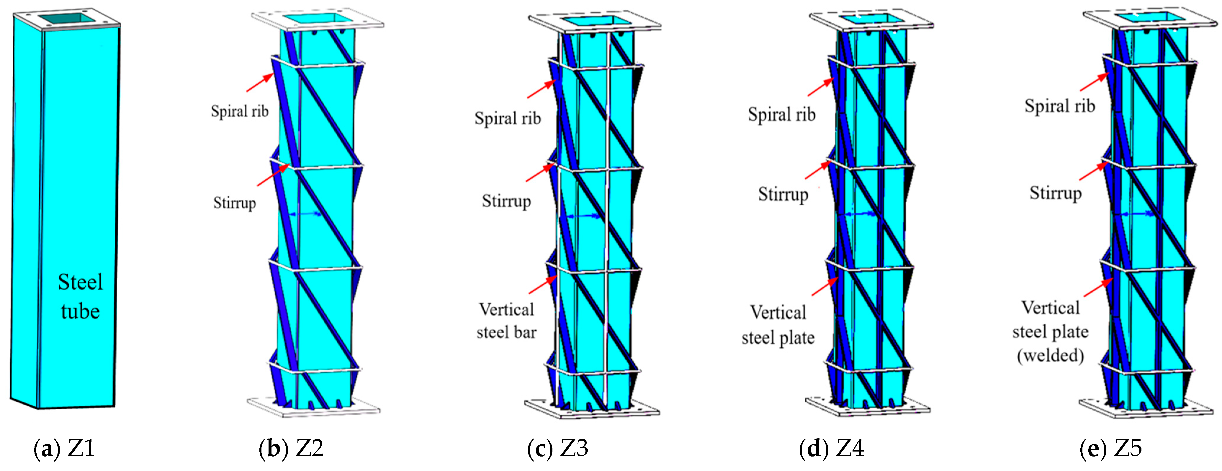
To investigate the confinement effect of helical stiffening ribs on concrete columns under axial compression, five different cross-sectional concrete-filled square steel tube specimens were designed. These specimens were constructed using square steel tubes (Q235B), helical ribs (Q235B), vertical steel plates (Q235B), vertical rebars (HRB400E), and concrete (C30). Specific parameters are detailed in Figure 1 and Figure 2, and Table 1. The mechanical properties of the various materials, determined through material tests, are listed in Table 2 and Table 3 [24,25].
A hydraulic servo-controlled long-column compression testing machine was selected to conduct axial compression tests on the specimens, with a total of five displacement gauges positioned to measure specimen deformations under axial loading. The loading device is shown in Figure 3. To ensure the proper operation of the loading device, a pre-load of 20 kN was applied to the specimens. The specimens were initially loaded up to the yield load under load control at a rate of 50 kN/min. After yielding, the loading was switched to displacement control at a rate of 0.1 mm/min. The test was terminated when the load decreased to 85% of the peak load.

2.2. Damage Phenomenon

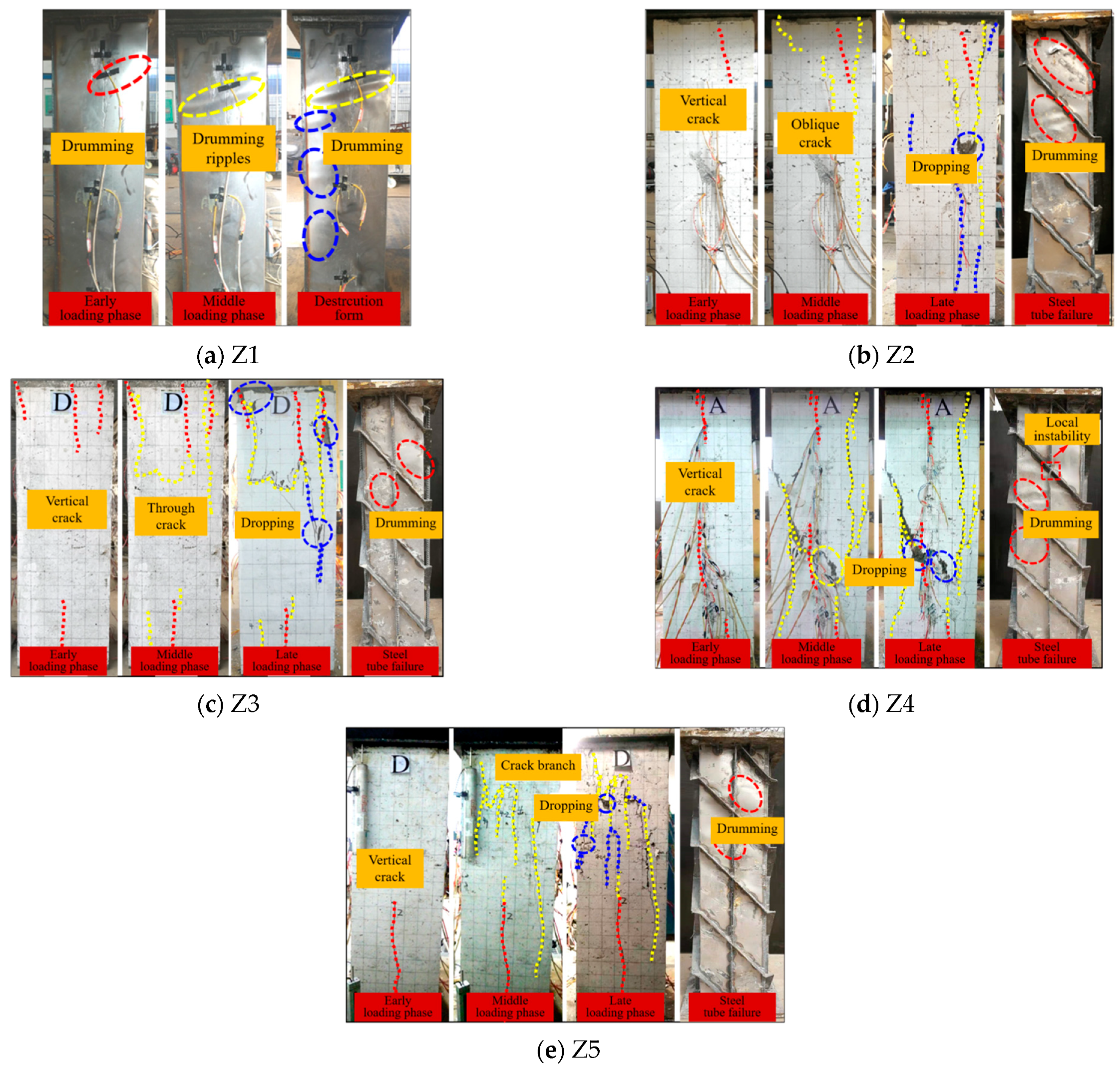
From the failure processes of each specimen (Figure 4), the following observations were made: for specimen Z1, initial buckling of the upper steel tube occurred, forming inclined buckling ripples as the load increased. At peak load, the internal concrete was crushed and connected buckling ripples formed at the bottom of the structure. Specimen Z2 exhibited vertical cracks first at the outer concrete layer 150 mm below the top plate, gradually extending towards the centre. Upon reaching the ultimate load, the main concrete crack spiralled along the helical ribs, accompanied by surface concrete spalling. At an axial compression of 1130 kN for specimen Z3, vertical cracks appeared in both the top and bottom outer concrete layers. With increasing stress, the cracks extended towards the middle of the specimen and concrete spalling occurred at the corners of the top plate. Specimen Z4 developed a 200 mm crack at the top when loaded to 975 kN. After reaching peak load, the crack began to peel and exhibited slight spalling, with the width increasing as the load capacity decreased. Ultimately, the intersection of cracks led to concrete delamination and failure. Specimen Z5 showed minor cracks in the bottom outer concrete after loading to 930 kN. Continued loading caused these cracks to propagate upwards, forming multiple branching cracks. After the peak load, the load-bearing capacity continued to decrease, widening surface cracks and leading to concrete spalling and crushing.
After completing the test loading and removing the external concrete casing, observations of the buckling patterns of the internal steel tubes revealed the following: the thin-walled steel tube of specimen Z2 buckled between two stiffening ribs, with no apparent deformation observed in the spiral stiffening ribs. Compared to specimen Z1, there was an improvement in localized buckling. The number of localized buckles in the steel tube wall of specimen Z3 had significantly reduced, with no noticeable deformation observed in the spiral ribs or vertical steel bars. In specimen Z4, localized buckling occurred in the middle and upper parts of the steel tube, with buckling appearing after the instability of the vertical steel plates. The surface of the steel tube in specimen Z5 exhibited slight buckling, which was minor in severity, and there was no noticeable buckling of the vertical plates.

2.3. Load–Displacement Curve

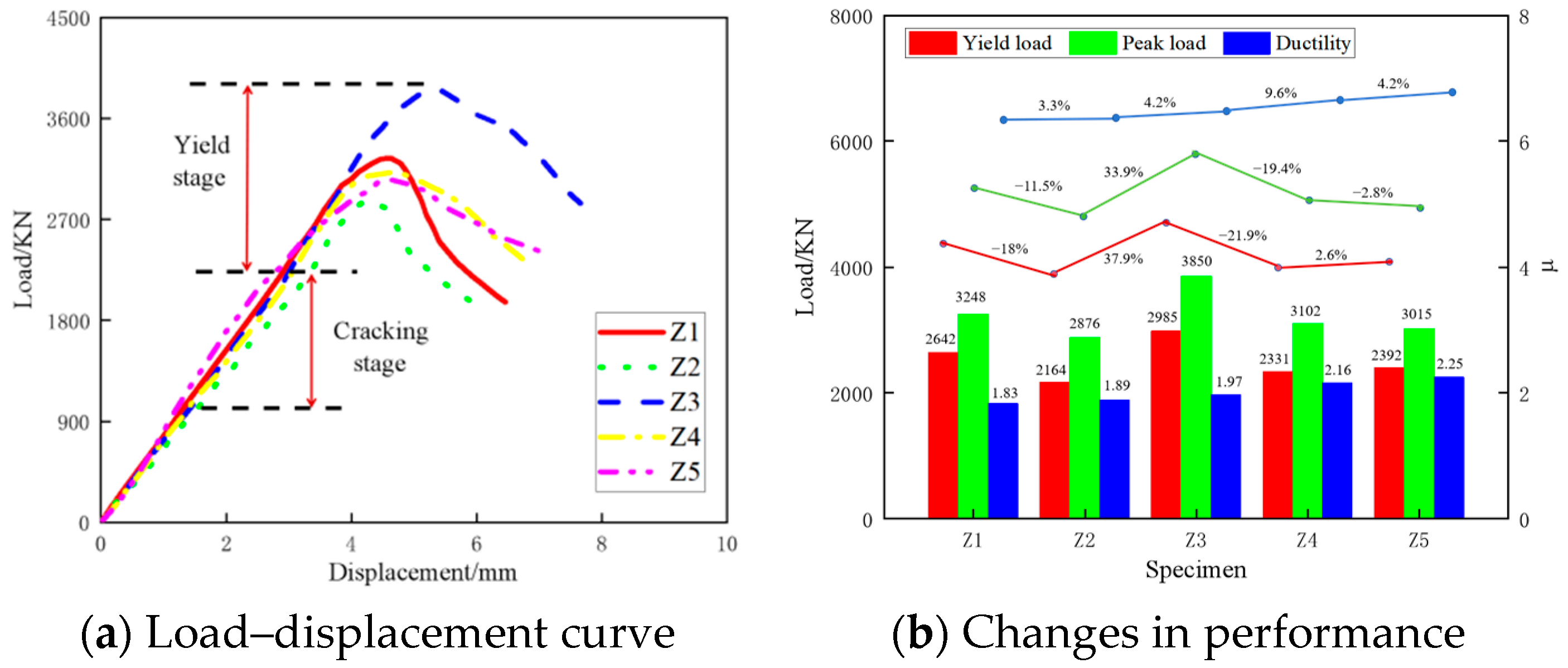
The load–displacement curves for each specimen are depicted in Figure 5a, showing three distinct phases: elastic, elastoplastic, and failure. During the loading phase, the curves exhibit similar slopes, indicating consistent initial stiffness of the components. Upon reaching peak load, the curves enter the descending phase. Compared to specimen Z1, the curves for specimens Z3, Z4, and Z5 exhibit a more gradual descent, indicating the significantly enhanced ductile behaviour of the components.
Comparing the performance variations of each specimen (Figure 5b), it was found that the ordinary concrete-filled steel tube specimen (Z1) had a buckling load of 2642 kN and a peak load of 3248 kN, with a ductility coefficient (µ) of 1.83. Compared to specimen Z1, the ordinary spiral stiffener-reinforced specimen (Z2) showed a 3.3% increase in ductility coefficient, while the yield load and peak load decreased by 18% and 11.5%, respectively. This reduction was attributed to the severe damage to the encased concrete, which weakened the specimen’s load-bearing performance. In contrast, the spiral rib-vertical reinforcement specimen (Z3) exhibited a significant improvement over Z2, with the yield and peak loads increasing by 37.9% and 33.9%, respectively, and an increase in ductility coefficient of 4.2%. This indicates a notable enhancement in the overall load-bearing performance of the specimen. Specimens Z4 and Z5, which incorporate spiral ribs and vertical plates, showed improved deformation capacity compared to Z3. However, both the yield load and peak load decreased by approximately 20%.

2.4. Mechanism of Spiral Rib Confinement

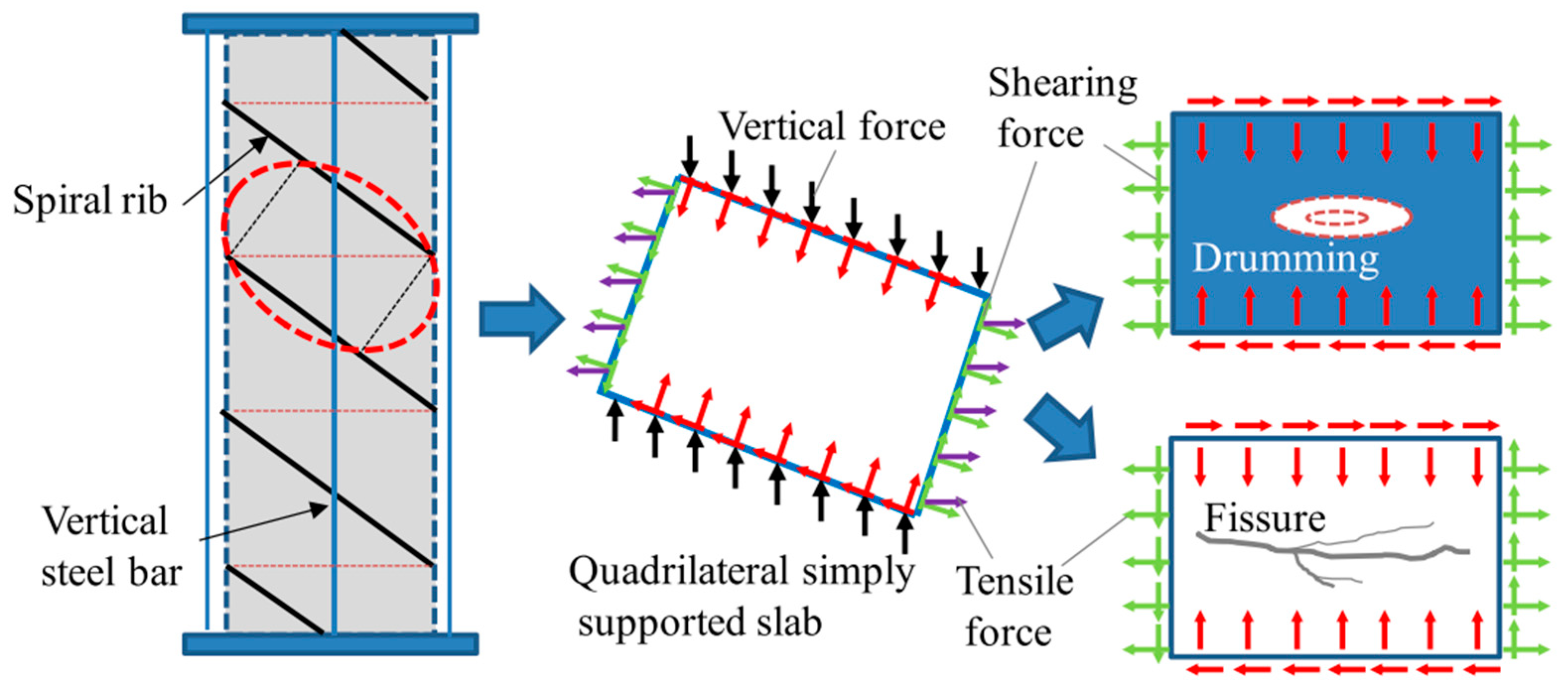
Comparison of the experimental phenomena, failure modes, buckling states of the steel tubes, and load–displacement relationships of various specimens under an axial compressive load revealed that the spiral rib-reinforced concrete-filled steel tube composite column (Z3) exhibits the best overall mechanical performance. The analysis of its working mechanism is as follows: the composite column is equipped with spirally distributed stiffening ribs on the exterior of the steel tube, dividing the concrete and steel tube into several helical belt-like structures. Under vertical loads, the spiral ribs, arranged at an angle, transform the vertical force into shear forces along the direction of the spiral ribs and vertical compressive forces. The concrete, subjected to this combined compressive-shear action, experiences diagonal cracking. The thin-walled steel tube under the constraint of the spiral ribs behaves similarly, undergoing buckling under the combined compressive-shear action. Additionally, the steel tube is subjected to circumferential compression and tensile forces from the internal concrete. The horizontal tensile forces are also decomposed along the angle of the spiral ribs, transforming them into tensile and shear stresses. The stress distribution and load-bearing mechanism are illustrated in Figure 6.

3. Spiral Rib Steel Tube Buckling Analysis

3.1. Theoretical Analysis Method

3.1.1. Mechanical Model

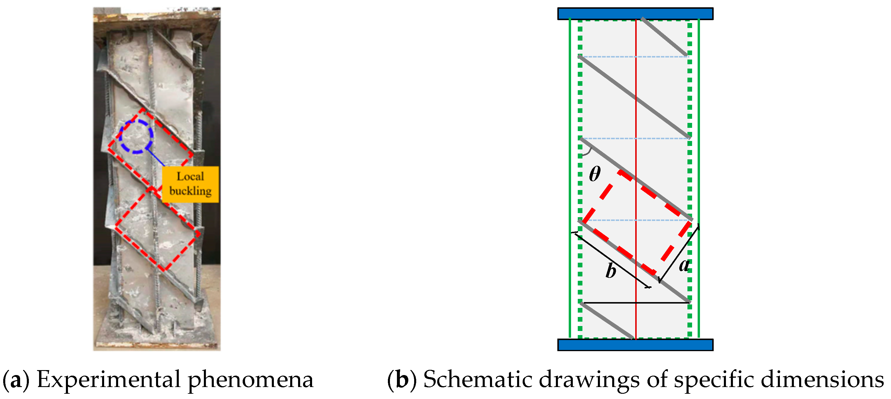
Currently, common methods for analyzing structural stability involve using analytical approximate techniques [28]. Based on the axial compression failure mode and the confinement mechanism of the spiral rib-reinforced components, local buckling of the steel tube in specimen Z3 primarily occured within the parallelogram-shaped regions formed by the spiral ribs, as illustrated in Figure 7a. To analyze the local buckling performance of the thin-walled steel tube, the most deformed rectangular thin steel plate region was selected for study, as shown in Figure 7b.
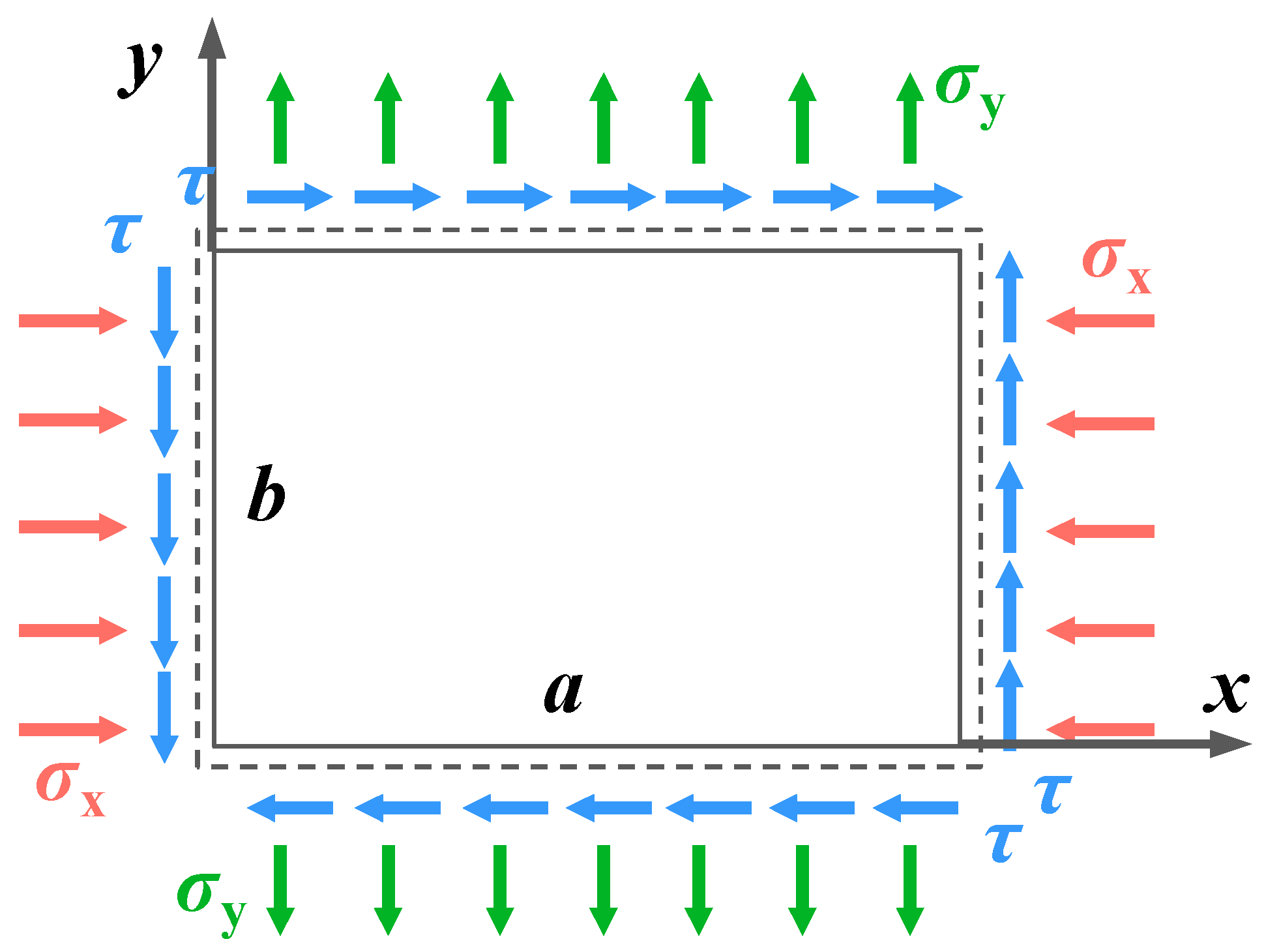
Consider a rectangular thin steel plate with length (a), width (b), and thickness (t) as the analysis unit. The boundary conditions and loading characteristics of this rectangular unit are determined based on the loading conditions of the specimen. The dimensions of this rectangular calculation unit are related to the geometric dimensions of the specimen as follows:
{ a = d s sin θ tan θ b = d s tan θ cos θ d s cos θ tan θ
where ds is the width of the steel tube, θ is the angle between the spiral stiffening rib and the longitudinal axis of the steel tube’s outer wall.
In the buckling analysis of the thin plate model, consider the combined effects of the compressive load (σx), tensile load (σy), and shear load (τ). The axial load ratio is given by β = σy/σx = −0.2. The mechanical calculation unit and the coordinate system used are shown in Figure 8. For different aspect ratios (γ), 0.8, 1.2, 1.5, 2.0, 3.0, 4.0, and stress ratios (S = σx/τxy), 1.28, 1.52, 1.79, 2.13, a total of 24 thin plates were analyzed. The Ritz method was employed to calculate the critical buckling load coefficients for each plate.

3.1.2. Assumptions of Thin Plate Stability Theory

To analyze a thin plate, we established a coordinate system with the xoy plane as the plane within the plate and the z-axis represents the thickness direction of the plate, as illustrated in Figure 9.
Due to the small deflection bending issues in thin plates, the following computational assumptions are introduced:
(1)
The linear strain of the mid-surface normal direction is not taken into consideration, which results in εz = 0:
w = w ( x , y )
(2)
The minor stress components τzx, τzy, and σz are significantly smaller compared to the other stress components. Therefore, the shear strains (γzx, γzy) and normal strain (εz) induced by these components are neglected. This simplification transforms the problem of small deflection bending of the thin plate into a plane stress problem, governed by the following physical equations:
{ ε x = 1 E ( σ x μ σ y ) ε y = 1 E ( σ y μ σ x ) γ xy = 2 ( 1 + μ ) E τ xy
(3)
In the context of small deflection bending of a thin plate, longitudinal displacements along the mid-surface of the plate are neglected. When the mid-surface of the plate undergoes bending deformation, its projected shape, including its line segments and area, remains unchanged on the xoy plane:
( ε x , ε y , γ xy ) z = 0 = 0

3.1.3. Thin Plate Bending Equation

To calculate the buckling load of a plate using the energy method, we constructed the total potential energy function for the plate under the assumptions of small deflection theory. We neglected the internal forces caused by deviations from the mid-plane of the plate:
= U V
U = D 2 0 b 0 a [ ( 2 w x 2 + 2 w y 2 ) 2 2 ( 1 μ ) ( 2 w x 2 2 w y 2 ) ( 2 w x y ) 2 ] d x d y
D = E t 3 12 ( 1 μ 2 )
where ∏ is the total potential energy, U is the strain energy, V is the external potential energy (Formula (8)), D is the bending stiffness of the plate, E is the modulus of elasticity of the material, μ is Poisson’s ratio; m and n are the half-wavelengths in the X and Y directions, respectively, after the buckling of the thin plate; Amn is coefficients, and ω is the deflection surface function that satisfies the boundary conditions of the plate (Equation (9)).
V = t 2 0 b 0 a [ σ x ( w x ) 2 + σ y ( w y ) 2 2 τ xy ( w x w y ) ] d x d y
w ( x , y ) = m = 1 n = 1 A mn sin m π x b sin n π y a
Substituting Equations (6), (8) and (9) into Equation (5) and applying the principle of stationary potential energy establishes a system of linear algebraic equations. When this system has several sets of solutions, the smallest value among them represents the buckling load.
{ A 11 = 0 A 12 = 0 A mn = 0

3.1.4. Critical Buckling Stress

For a simply supported thin plate subjected to compressive, tensile, and shear loads, the total strain energy can be expressed as follows when calculating the critical elastic buckling stress using theoretical methods:
U = π 4 a b D 8 m = 1 n = 1 A mn 2 ( m 2 a 2 + n 2 b 2 ) 2
The total work done by the external loads acting on the thin plate includes three components; axial forces in the x and y directions, and the work done by shear stresses in the xy direction.
V = t σ x 2 0 a 0 b ( w x ) 2 d x d y + t σ y 2 0 a 0 b ( w y ) 2 d x d y t τ xy 0 a 0 b ( w x w y ) d x d y = a b t π 2 8 m = 1 n = 1 A mn 2 ( σ x m 2 a 2 + σ y n 2 b 2 ) 4 t τ xy m = 1 n = 1 p = 1 q = 1 A mn A pq m n p q ( m 2 p 2 ) ( n 2 q 2 )
In the Formula, m, n, p, and q are all integers that must satisfy the condition that they are odd. Assuming the aspect ratio of the plate is γ = a/b, and letting k1 = σxb2t/2, k2 = σyb2t/2, k3 = τxyb2t/2, simplifying Equation (12) and substituting it into Equation (5) gives
= m = 1 M n = 1 N A mn 2 [ ( m 2 + γ 2 n 2 ) 2 k 1 γ 2 m 2 k 2 γ 4 n 2 ] 32 k 3 γ 3 π 2 m = 1 n = 1 p = 1 q = 1 A mn A pq m n p q ( m 2 p 2 ) ( n 2 q 2 )
M and N represent the minimum values required for the convergence of the results. When the derivative of Amn equals zero, we obtain a homogeneous linear system of equations. The solution to this system gives the critical buckling stress of the thin plate.
A mn [ ( m 2 + γ 2 n 2 ) 2 k 1 γ 2 m 2 k 2 γ 4 n 2 ] 32 k 3 γ 3 π 2 p = 1 q = 1 A pq m n p q ( m 2 p 2 ) ( n 2 q 2 ) = 0
[ C ] L × L { A } L × 1 = 0
The equation [C]L×L is an L-order matrix where L = M × N; {A}L×1 represents a column vector of M × N unknown coefficients Amn; by solving |[C]L×L| = 0, we obtain the critical buckling coefficients. However, solving the determinant of the M × N order matrix is complex. Therefore, for the thin plates subjected to biaxial loads and shear loads, the corresponding critical stress relationships are proposed.
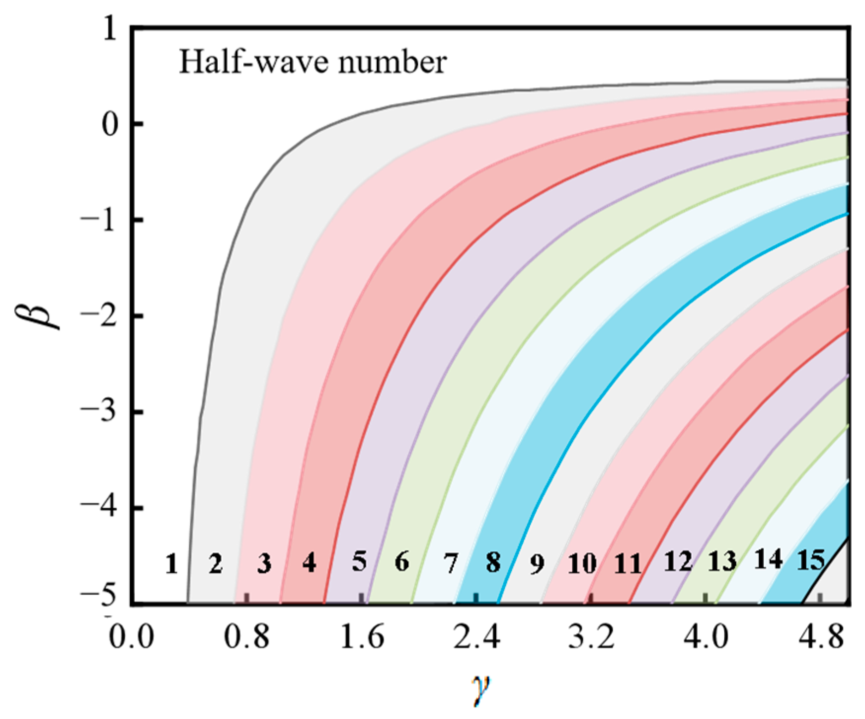
{ k 1 k 1 c r + k 2 k 2 c r + ( k 3 k 3 c r ) 2 = 1 k 1 k 1 c r + k 2 k 2 c r + ( k 3 k 3 c r ) 2 = e β γ 20 ( τ x y τ c r ) 2 ( τ xy τ c r ) < 0.25   or   γ 1.6 ( τ xy τ c r ) 0.25   and   γ > 1.6
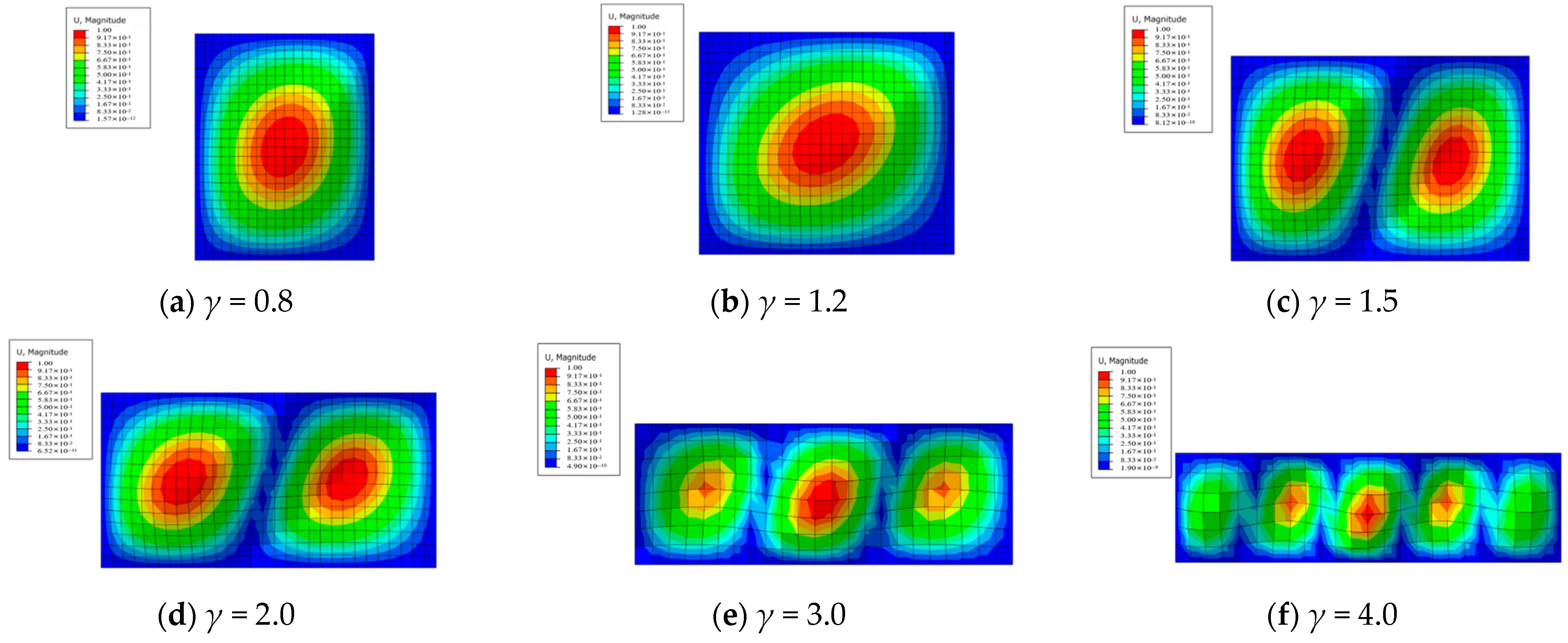
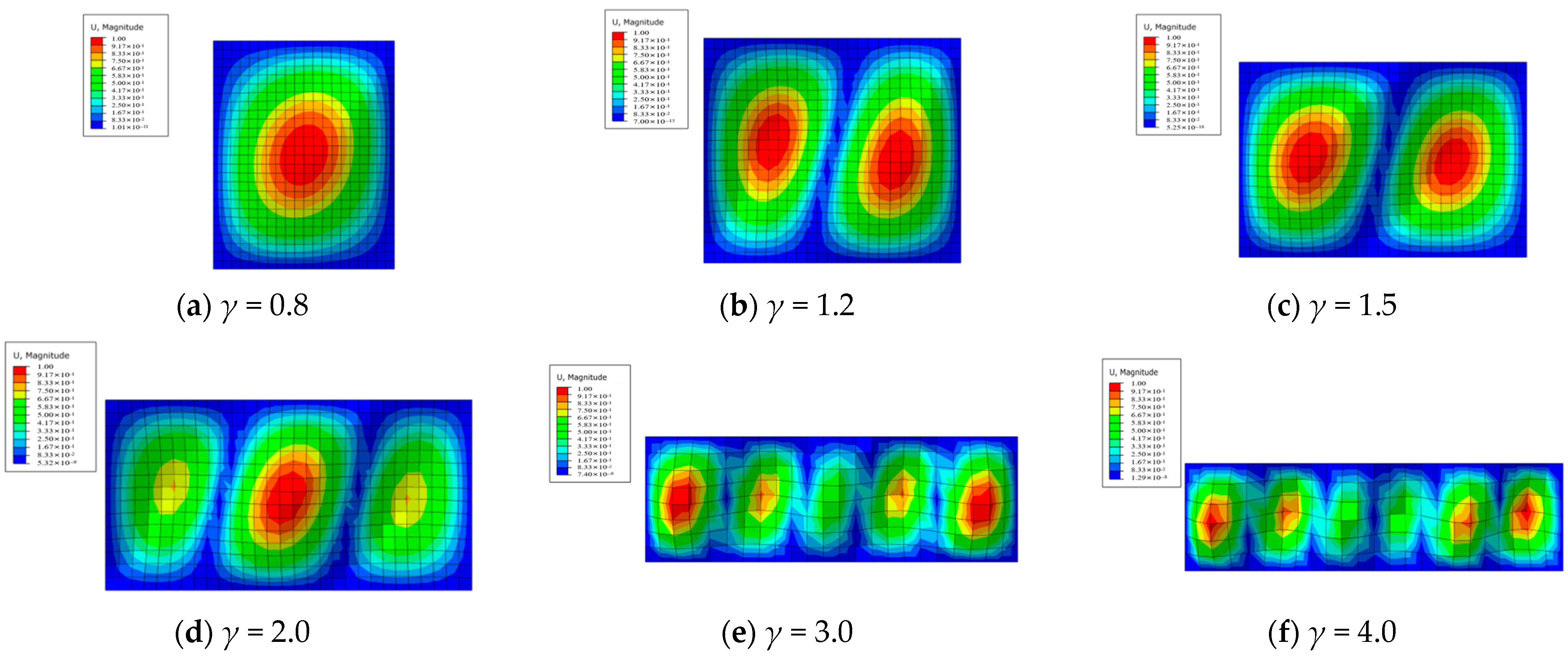
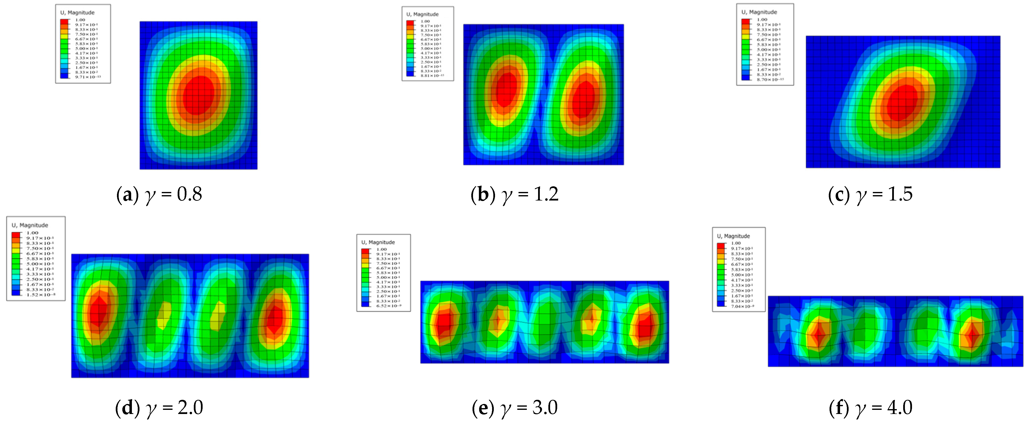
In the equation, β represents the ratio of axial loads, and the half-wavelengths in the x and y directions are determined according to Figure 10. The critical buckling solutions for the plate under 24 different loading combinations are computed and summarized in Table 4.

3.2. Numerical Analysis

We performed numerical analysis on the buckling of thin plates under complex combined loading conditions, then compared and validated the results with formulaic calculations.

3.2.1. Linear Buckling Model

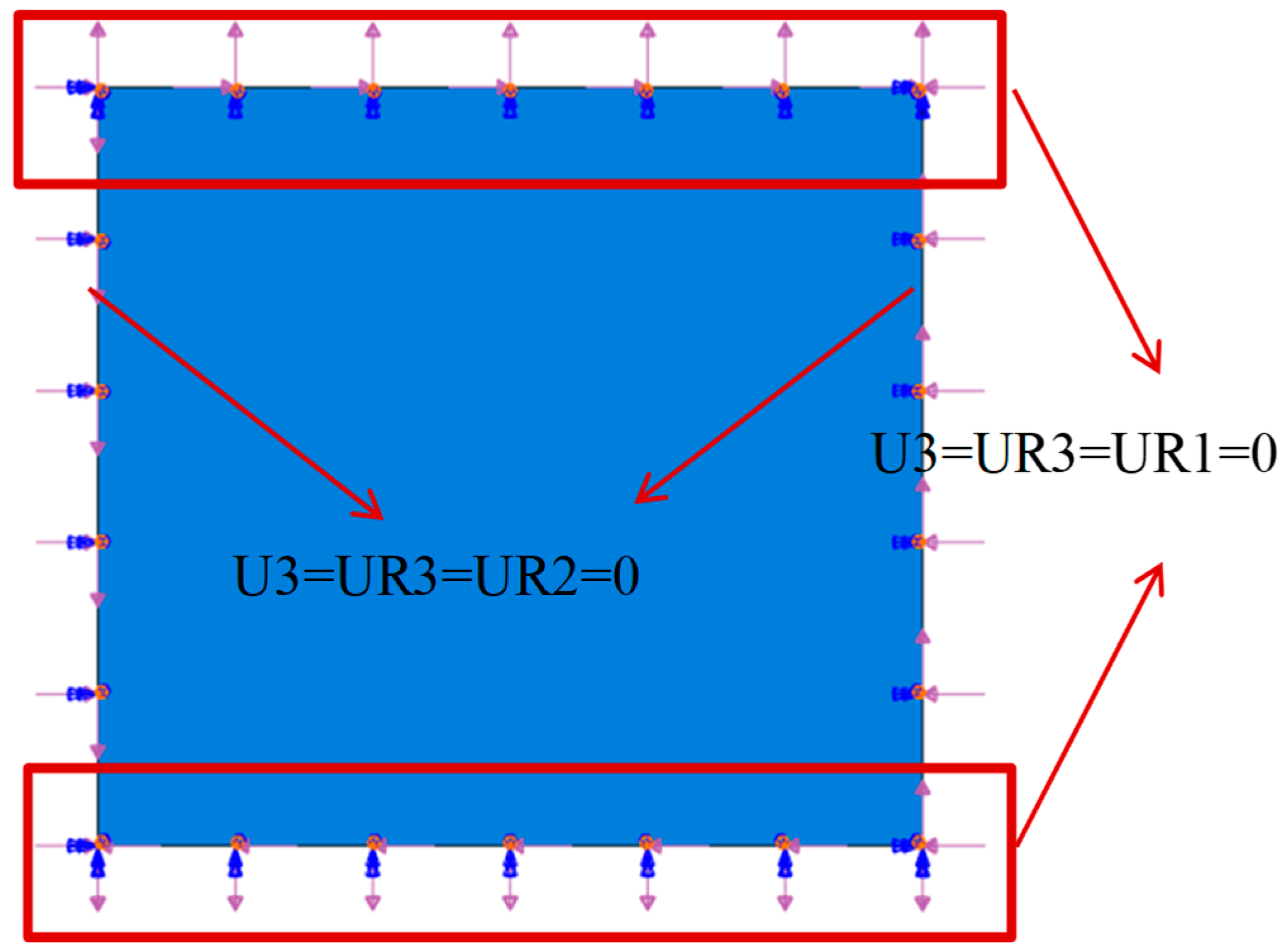
Using the eigenvalue method, a model was established with ABAQUS 6.14 software to analyze the buckling behaviour of a thin plate. The plate was analyzed using 3D shell elements. Compressive (tensile) loads were applied through edge loads on the shell—normal edge traction, while shear forces were applied through edge loads on the shell—shear edge traction. Figure 11 illustrates the finite element model of the thin plate (using a plate with an aspect ratio of γ = 1.2 as an example for buckling analysis). Each geometric edge was subjected to 1 N/mm edge loads, with the boundary conditions set as simply supported on all four sides. The dimensions of the rectangular thin plate were 495.5 × 436 × 4 mm, with an elastic modulus of E = 205 GPa and a Poisson’s ratio of μ = 0.3.

3.2.2. Buckling Mode Calculation

By performing eigenvalue buckling analysis, the first four buckling modes and the corresponding critical buckling load factors of the thin plate were obtained, as shown in Figure 12. As the number of modes increases, the eigenvalues (critical loads) also increase accordingly. The critical buckling loads of the thin plate model were determined from the buckling eigenvalues shown in the figure and are summarized in Table 5.
Simulations were conducted separately for 24 combinations of loading (γ = 0.8, 1.2, 1.5, 2, 3, 4; S = 1.28, 1.52, 1.79, 2.13) to analyze the buckling of the thin plate.
(1)
Under loading conditions with S = 1.28 and β = −0.2, the buckling modes are shown in Figure 13. The critical buckling stress values were computed based on the eigenvalues extracted from the output file, as summarized in Table 6.
(2)
Under loading conditions with S = 1.52 and β = −0.2, the buckling modes of the thin plate are shown in Figure 14. The corresponding critical buckling stresses are listed in Table 7.
(3)
Under loading conditions with S = 1.79 and β = −0.2, the buckling modes of the thin plate are shown in Figure 15. The corresponding critical buckling stresses are listed in Table 8.
(4)
Under loading conditions with S = 2.13 and β = −0.2, the buckling modes of the thin plate are shown in Figure 16. The corresponding critical buckling stresses are listed in Table 9.

3.3. Critical Buckling Capacity

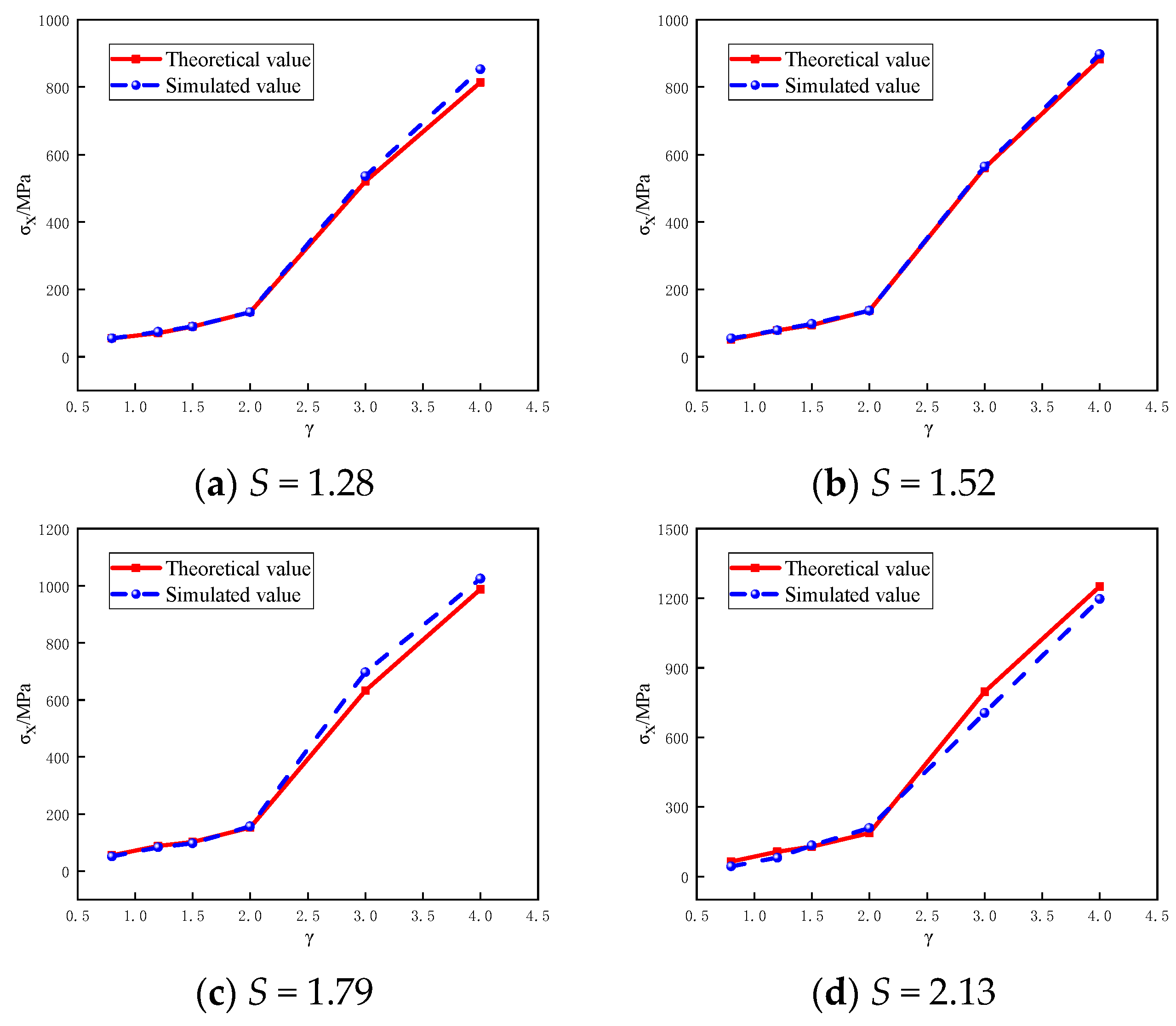
Based on the theoretical formulation and finite element eigenvalue analysis, the critical buckling stresses of a simply supported rectangular thin plate under combined compressive–tensile–shear loads were compared. The corresponding curves of elastic buckling stress are shown in Figure 17.
From Figure 17, it can be observed that the error between theoretical values and simulated values is less than 15%. Formula (16) can compute the elastic buckling load of a simply supported rectangular plate under biaxial and shear loads. Building upon this geometric relationship transformation, we can derive the critical buckling stress (σcr) formula for the steel pipes constrained by spiral ribs, as well as the formula for calculating the elastic buckling capacity (Ns,y) of spiral rib steel pipes.
σ cr = k 1 π 2 E 12 ( 1 μ 2 ) ( t s 2 tan 2 θ cos 2 θ d s 2 sin 5 θ )
N s , y = f y 1 × A sr + σ cr × A st
where k1 is the critical buckling coefficient of a four-sided simply supported rectangular thin plate under compression–tension–shear load; ts and ds are steel pipe width and steel pipe thickness, θ is the vertical angle between the spiral stiffener and the outer wall of the steel pipe, fy1 is the yield strength of spiral rib, Asr is the cross-sectional area of the spiral rib, and Ast is the cross-sectional area of the steel pipe.

4. Bearing Capacity

4.1. Impact Parameters

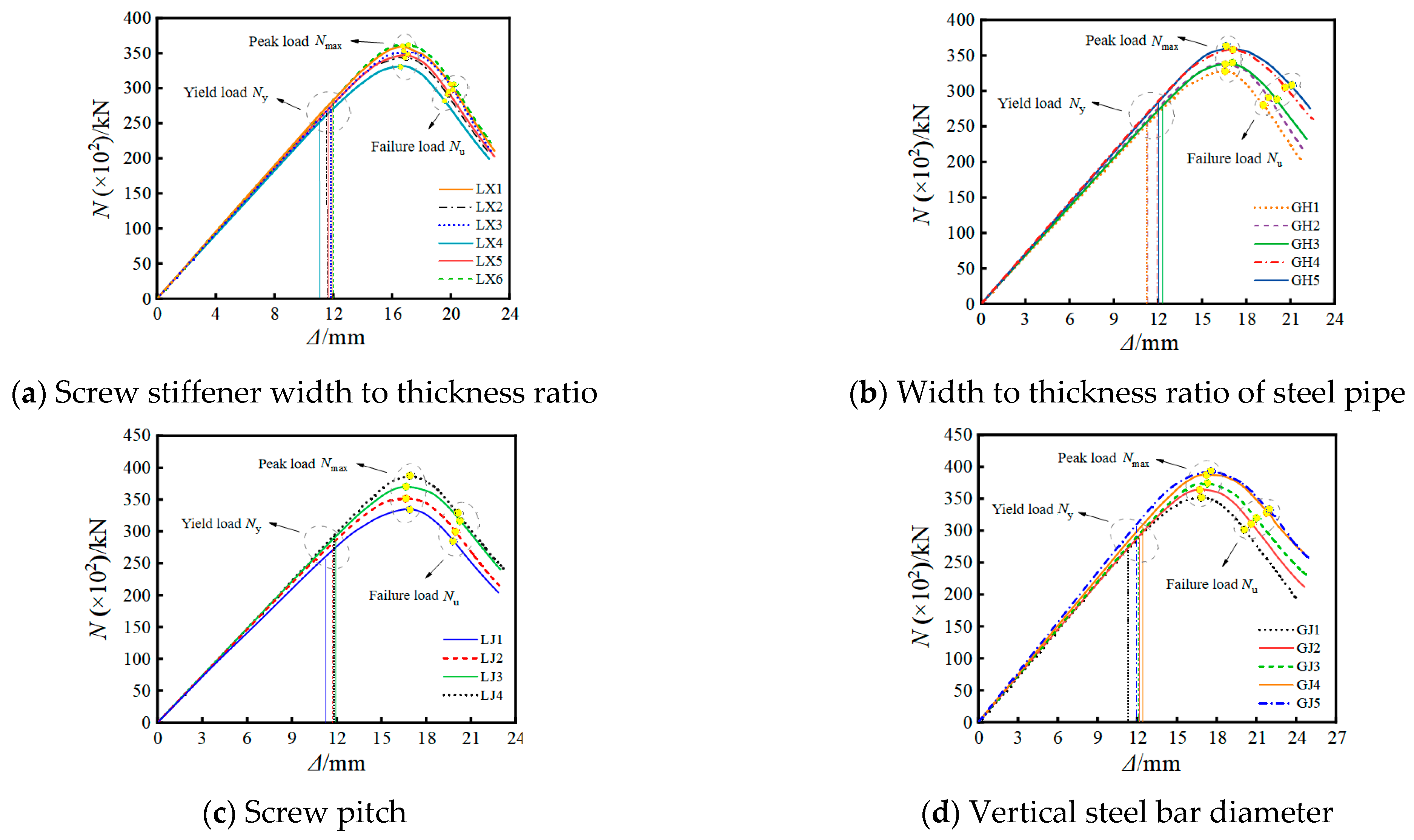
The axial compressive capacity of spiral rib-reinforced steel tube concrete columns is influenced by the combined effects of the concrete, steel tube, spiral ribs, and steel reinforcement. Considering the impacts of spiral ribs, steel tubes, and steel reinforcement, the influence of parameters such as the rib width-to-thickness ratio (LX), steel tube width-to-thickness ratio (GH), pitch (LJ), and the vertical steel bar diameter (GJ) on the axial performance of composite columns is analyzed. Numerical analyses provided load–displacement curves for spiral rib-reinforced steel tube concrete columns under different parameter conditions [26,27], as illustrated in Figure 18.

4.2. Bearing Capacity of Outsourced Concrete

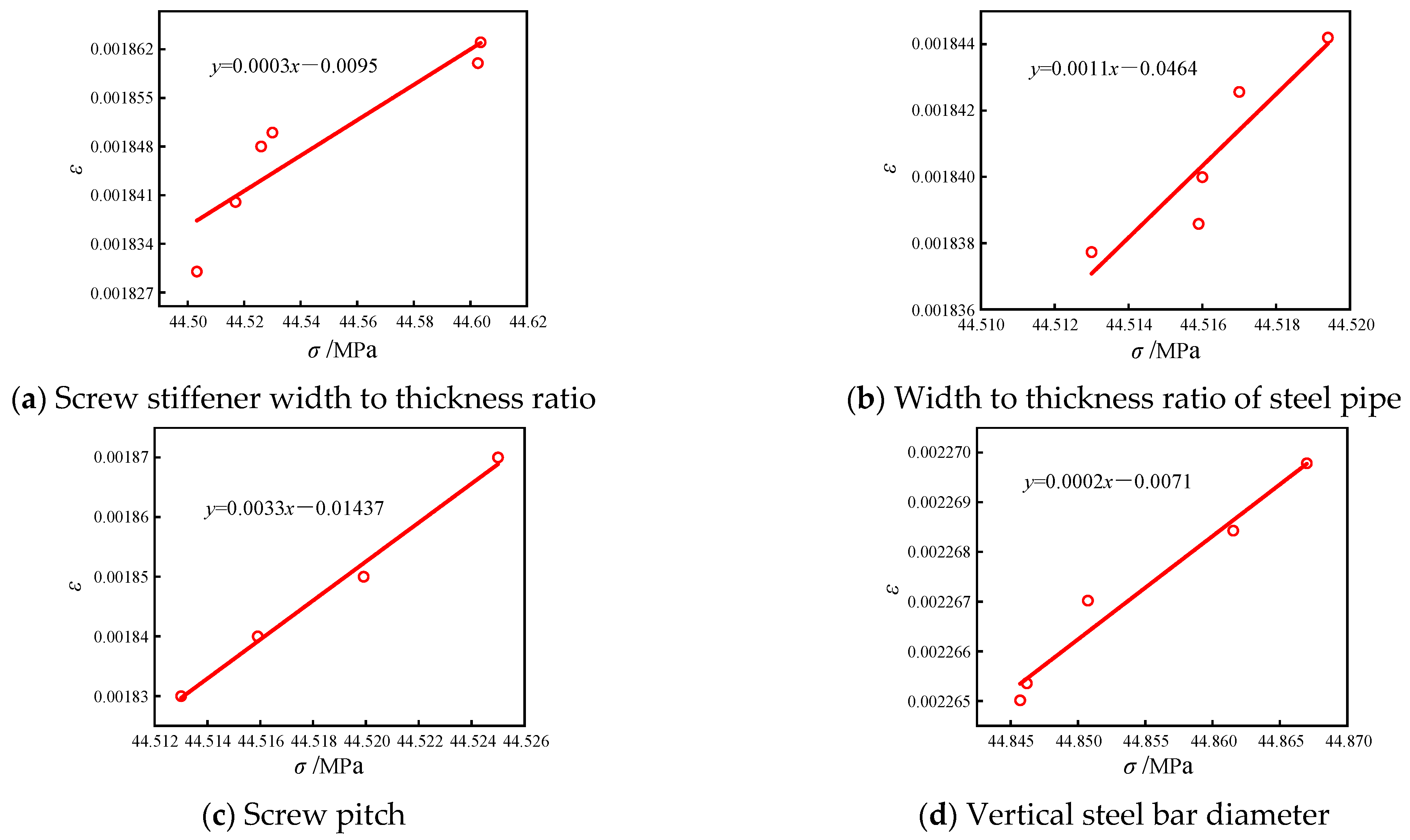
We can fit the correlation between influencing parameters and the stress in external concrete (Figure 19) and introduce a reduction factor for concrete strength to reflect the loss of load-bearing capacity due to the cracking and spalling of the concrete (Formulas (19) and (20)). We can then calculate the external concrete bearing capacity of spiral rib-reinforced steel tube concrete columns using Formula (21).
α 1 = 0.0003 b r / t r + 0.0011 d s / t s + 0.0033 p + 0.0002 n s
α = α 0 + α 1 = 0.61 + ( 0.0003 b r / t r + 0.0011 d s / t s + 0.0033 p + 0.0002 n s )
N oc = α × A oc × f c
where α is the reduction coefficient of external concrete strength, α1 is the offset value produced by increasing the contact surface, and α0 is the strength loss caused by the spalling of concrete. br/tr is the ratio of helical rib width to thickness, ds/ts is the width and thickness ratio of steel pipe, p is the ratio of pitch to column height, ns is the vertical bar diameter, Noc is the clad concrete bearing capacity, Aoc is the external concrete cross-section area, and fc is the design value of the compressive strength of the concrete axis.

4.3. Core Concrete Bearing Capacity

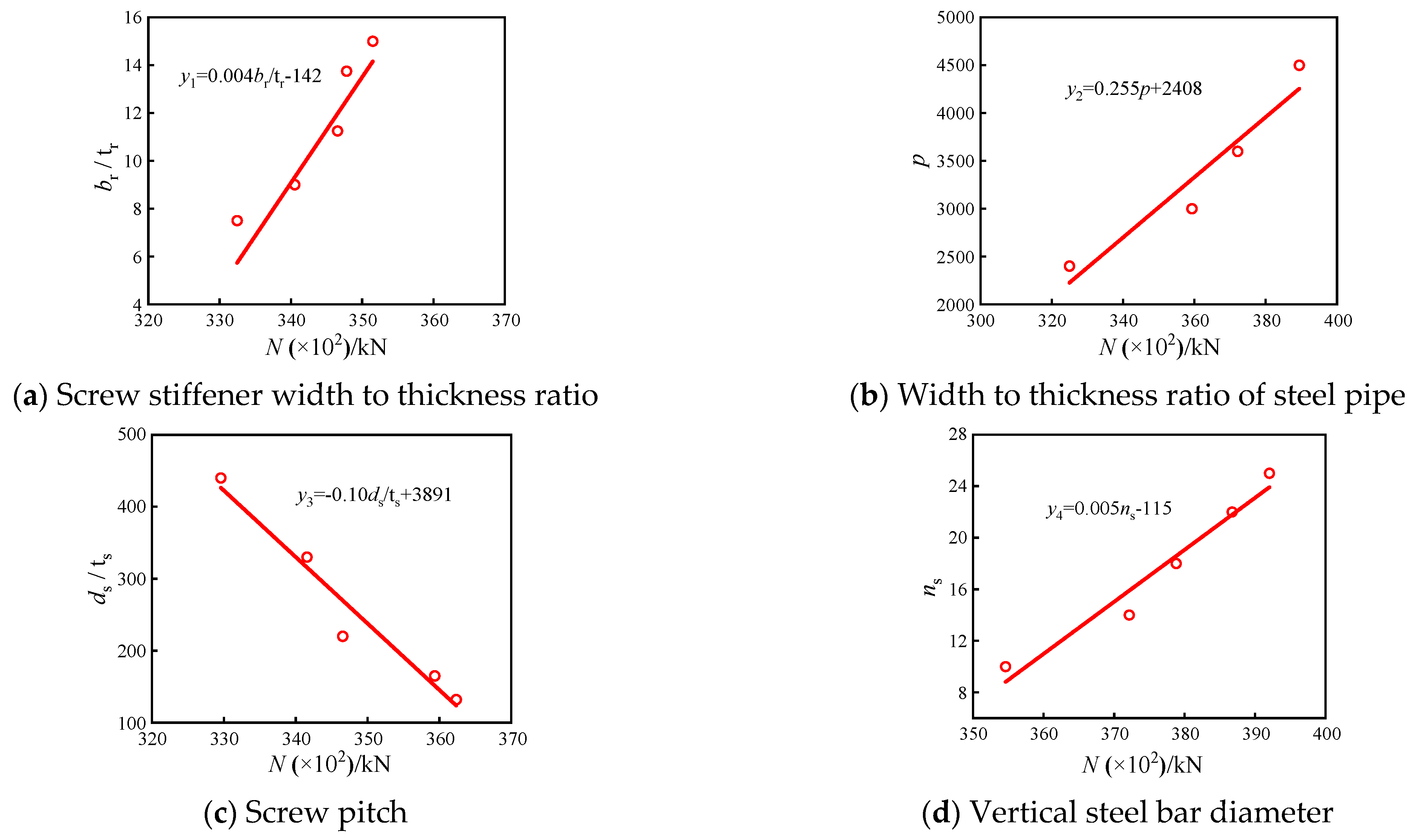
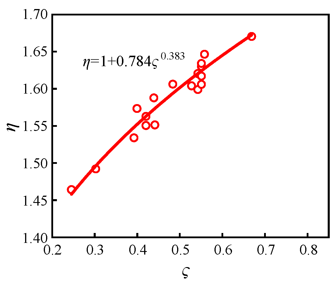
We used the spiral rib steel tube confinement factor to measure the steel confinement effect on the core concrete of steel tube concrete sections (Formulas (22) and (23)), and fitted the curves as shown in Figure 20. We introduced the enhancement factor of core concrete under hoop confinement (Formula (24)) to assess the reinforcing effect of spiral rib steel tube confinement on core concrete materials, as depicted in Figure 21. We calculated the core concrete bearing capacity using Formula (25):
ς = ( A s 1 f y 1 + A s 2 f y 2 ) × ( 1 + χ ) A c 2 f c
χ = 0.004 b r / t r + 0.255 p 0.10 d s / t s + 0.005 n s
η = 1 + 0.784 ς 0.383
N cc = η × A cc × f c
where ς is the spiral rib steel pipe restraint coefficient, χ is the comprehensive influence coefficient of steel pipe strength, η is the core concrete strengthening coefficient, Ncc is the core concrete bearing capacity, Acc is the core concrete cross-section area, and fc is the design value of compressive strength of concrete axis.

4.4. Axial Compressive Capacity of Composite Column

Through the principle of superposition, the axial compressive capacity of the spiral rib-reinforced steel tube concrete composite columns is determined by the combined contributions of spiral rib steel tubes, external concrete, core concrete, and vertical steel reinforcement:
N y = N s , y + N oc + N cc + N b
N y = ( f y 1 × A sr + σ c r × A s t ) + α x ( A o c × f c ) + η x ( A c c × f c ) + A s b × f y 2
where Ny is the axial compressive capacity of the composite column, Ns,y is the buckling capacity of spiral ribbed steel pipe, Noc is the external concrete bearing capacity, Ncc is the core concrete bearing capacity, and Nb is the bearing capacity of the vertical reinforcement.
The buckling capacity of specimen Z3 was calculated to be 2560 kN, with an error of 5.2% compared to the experimental value of 2700 kN. Furthermore, the axial buckling capacities under compressive loads for various composite columns obtained through finite element parametric analysis are summarized in Table 10. The errors between the formula calculated values and the simulated values are within 10%, indicating that the formula is suitable for estimating the elastic buckling capacity of composite structures constrained by spiral rib reinforcement under axial compression loads.

5. Conclusions

To investigate the confinement effect of spiral ribs on concrete columns, axial compression tests were conducted to observe the failure modes of square steel tube concrete columns with different cross-sections. The confinement mechanism provided by spiral ribs was analyzed. By integrating theoretical and numerical methods, a formula for calculating the critical buckling capacity of spiral rib-reinforced thin-walled structures was derived. The axial load-bearing capacities of each specimen were validated accordingly. The specific conclusions are as follows:
(1)
The failure mode of steel tube concrete columns under axial compression typically involves the crushing of the core concrete and the outward buckling of the steel tube. In the case of spiral rib-reinforced composite columns, the external concrete casing tends to crack diagonally along the direction of the spiral ribs. The buckling of the steel tube wall occurs predominantly between the spiral ribs. Spiral ribs significantly enhance the ability of thin-walled steel tube concrete components to resist local buckling;
(2)
In comparison to ordinary steel tube concrete columns, using a single spiral rib restraint enhances the ductility of the structure but can reduce its load-bearing capacity. However, when spiral ribs are combined with steel bars (welded), the load-bearing capacity and ductility of the structure increase by 18.5% and 7.7%, respectively. Spiral ribs effectively delay the buckling of thin-walled steel tubes, thereby enhancing both the load-bearing capacity and deformation capability of the structure to a certain extent;
(3)
The mechanism of spiral rib confinement works as follows: spiral ribs on the outer wall of the steel tube divide the concrete and the steel tube into several spiral band-like structures. Under an axial compressive load, the vertical force is converted into shear force along the direction of the spiral ribs and vertical pressure. The component undergoes a combined compression–shear stress pattern, thereby restricting the buckling of the steel tube and lateral deformation;
(4)
The axial compressive load capacity of spiral rib-reinforced steel tube concrete composite columns is influenced by the spiral ribbed steel tube, external concrete, core concrete, and vertical steel bars. Based on the eigenvalue buckling mode method, a formula for the critical buckling stress of spiral rib-reinforced steel tubes is proposed. By applying the superposition principle, the experimental and numerical simulations and the theoretical calculations show that the load-bearing capacities of the composite columns are generally consistent.

Author Contributions

Conceptualization, P.T., K.W., J.N. and Z.X.; methodology, P.T., K.W. and Z.X.; software, K.W., J.N. and K.L.; validation, Z.X. and K.L.; formal analysis, P.T.; investigation, K.W., J.N. and K.L.; resources, Z.W.; data curation, Z.W.; writing—original draft preparation, P.T.; writing—review and editing, Z.W.; visualization, P.T.; supervision, J.N., Z.X. and K.L.; project administration, J.N. and K.L.; funding acquisition, Z.W. All authors have read and agreed to the published version of the manuscript.

Funding

The authors would like to thank the financial support from the Future City Construction and Management Innovation Joint Research Center Leadership Funded Project (2024WHZ0220) and the General Project of the Shaanxi Provincial Natural Science Basic Research Program (2024JC-YBMS-383).

Data Availability Statement

The original contributions presented in the study are included in the article, further inquiries can be directed to the corresponding author.

Conflicts of Interest

Authors Penggang Tian, Kai Wang, Jianhui Niu, Zhixun Xie and Kangning Liu were employed by the company SCEGC City of Future Scientific and Technological Innovation Co., Ltd. The remaining authors declare that the research was conducted in the absence of any commercial or financial relationships that could be construed as a potential conflict of interest.

References

  1. Ding, J.; Wu, H.; Zhao, X. Current situation and discussion of structural design for super high-rise buildings above 250 m in China. J. Build. Struct. 2014, 35, 1–7. [Google Scholar] [CrossRef]
  2. Lee, H.J.; Choi, I.R.; Park, H.G. Eccentric Compression Strength of Rectangular Concrete-Filled Tubular Columns Using High-Strength Steel Thin Plates. J. Struct. Eng. 2016, 143, 04016228. [Google Scholar] [CrossRef]
  3. Wang, Z.-B.; Tao, Z.; Yu, Q. Axial compressive behaviour of concrete-filled double-tube stub columns with stiffeners. Thin Walled Struct. 2017, 120, 91–104. [Google Scholar] [CrossRef]
  4. Xu, B.; Wu, F.; Xu, G.; Kong, H.; Gu, G.; Yu, X. Experimental study on the axial compressive performance of CFST short columns with different stiffeners. Sichuan Build. Sci. 2018, 44, 43–46. [Google Scholar] [CrossRef]
  5. Al-Zubaidi, I.; Abdel-Jaber, M.; Hunaiti, Y.; El-Nimri, R. Behavior of light-gauge steel short columns filled with normal and lightweight aggregate concrete under cincentrte under concentric axial loading. J. Appl. Eng. Sci. 2022, 20, 1040–1052. [Google Scholar] [CrossRef]
  6. Sulaiman, A.; Hunaiti, Y.; Abdel-Jaber, M.; Abdel-Jaber, M. Compressive behavior of light-gauge steel tubes filled with concrete containing recycled aggregates. Int. Rev. Appl. Sci. Eng. 2022, 13, 185–196. [Google Scholar] [CrossRef]
  7. Zuo, Z.L.; Liu, D.X.; Cai, J.; Yang, C.; Chen, Q.J. Experiment on T-Shaped CFT Stub Columns with Binding Bars Subjected to Axial Compression. Adv. Mater. Res. 2013, 838–841, 439–443. [Google Scholar] [CrossRef]
  8. Zuo, Z.-L.; Cai, J.; Chen, Q.-J.; Liu, X.-P.; Yang, C.; Mo, T.-W. Performance of T-shaped CFST stub columns with binding bars under axial compression. Thin Walled Struct. 2018, 129, 183–196. [Google Scholar] [CrossRef]
  9. Ge, Q.; Yang, F.; Dong, W.; Bian, Z. Unified solutions on axial bearing capacity of T-shaped concrete-filled steel tube short columns with binding bars. IOP Conf. Ser. Earth Environ. Sci. 2021, 636, 012024. [Google Scholar] [CrossRef]
  10. Ding, F.-X.; Luo, L.; Wang, L.; Cheng, S.; Yu, Z.-W. Pseudo-static tests of terminal stirrup-confined concrete-filled rectangular steel tubular columns. J. Constr. Steel Res. 2018, 144, 135–152. [Google Scholar] [CrossRef]
  11. Tan, Q.; Chen, Z.; Jing, C. Experimental investigation on mechanical performance and bearing capacity calculation of spiral stirrup-reinforced concrete-filled square steel tubular columns under eccentric compression. J. Build. Struct. 2020, 41, 102–109. [Google Scholar] [CrossRef]
  12. Teng, J.; Wang, J.; Lin, G.; Zhang, J.; Feng, P. Compressive behavior of concrete-filled steel tubular columns with internal high-strength steel spiral confinement. Adv. Struct. Eng. 2021, 24, 1687–1708. [Google Scholar] [CrossRef]
  13. Ding, F.-X.; Lu, D.-R.; Bai, Y.; Zhou, Q.-S.; Ni, M.; Yu, Z.-W.; Jiang, G.-S. Comparative study of square stirrup-confined concrete-filled steel tubular stub columns under axial loading. Thin Walled Struct. 2016, 98, 443–453. [Google Scholar] [CrossRef]
  14. Long, Y.; Zeng, L.; Wang, Y.; Cai, J. Elastic-plastic local buckling model of rectangular CFT columns under axial compression. Sci. Sin. Technol. 2019, 49, 35–43. [Google Scholar] [CrossRef]
  15. Liu, J.; Wang, K. Bending of anisotropic rectangle plates with four free edges on elastic foundation. Chin. J. Appl. Mech. 2003, 20, 103–106. [Google Scholar]
  16. Batista, M. New analytical solution for bending problem of uniformly loaded rectangular plate supported on corner points. IES J. Part A Civ. Struct. Eng. 2010, 3, 75–84. [Google Scholar] [CrossRef]
  17. Xu, T.; Xing, Y. Exact solutions for free vibrations of rectangular thin plates on the winkler foundation. Eng. Mech. 2014, 31, 43–48. [Google Scholar]
  18. Li, R.; Zheng, X.; Wang, H.; Xiong, S.; Yan, K.; Li, P. New analytic buckling solutions of rectangular thin plates with all edges free. Int. J. Mech. Sci. 2018, 144, 67–73. [Google Scholar] [CrossRef]
  19. Li, R.; Wang, B.; Lv, Y.; Zhang, Q.; Wang, H.; Jin, F.; Teng, F.; Wang, B. New analytic solutions for static problems of rectangular thin plates point-supported at three corners. Meccanica 2017, 52, 1593–1600. [Google Scholar] [CrossRef]
  20. Ullah, S.; Wang, H.; Zheng, X.; Zhang, J.; Zhong, Y.; Li, R. New analytic buckling solutions of moderately thick clamped rectangular plates by a straightforward finite integral transform method. Arch. Appl. Mech. 2019, 89, 1885–1897. [Google Scholar] [CrossRef]
  21. Tang, Z.; Fu, Z.; Fan, C. Generalized finite difference method for solving kirchhoff plate and winkler plate bending problems. Chin. J. Solid Mech. 2018, 39, 419–428. [Google Scholar] [CrossRef]
  22. Mijušković, O.; Ćorić, B.; Šćepanović, B. Accurate buckling loads of plates with different boundary conditions under arbitrary edge compression. Int. J. Mech. Sci. 2015, 101–102, 309–323. [Google Scholar] [CrossRef]
  23. Nazarimofrad, E.; Zahrai, S.M.; Kholerdi, S.E.S. Effect of rotationally restrained and Pasternak foundation on buckling of an orthotropic rectangular Mindlin plate. Mech. Adv. Mater. Struct. 2018, 25, 592–599. [Google Scholar] [CrossRef]
  24. GB 50010-2010; Code for Design of Concrete Structures. China Architecture Industry Press: Beijing, China, 2015.
  25. GB 50017-2017; Standard for Design of Steel Structures. China Architecture Industry Press: Beijing, China, 2017.
  26. Wang, Z.-S.; Han, J.-Y.; Wei, J.; Lu, J.-L.; Li, J.-L. The axial compression mechanical properties and factors influencing spiral-ribbed thin-walled square concrete-filled steel tube composite members. Case Stud. Constr. Mater. 2022, 17, e01510. [Google Scholar] [CrossRef]
  27. Wang, Z.; Su, Y.; Wei, J.; Lu, J.; Li, X. The Eccentric Compression Performance of Spirally Stiffened Thin-Walled Square Concrete-Filled Steel Tubular Laminated Composite Members. Buildings 2022, 12, 1151. [Google Scholar] [CrossRef]
  28. Coskun, S.B.; Ozturk, B. Elastic Stability Analysis of Euler Columns Using Analytical Approximate Techniques. Adv. Comput. Stab. Anal. 2012, 6, 115–132. [Google Scholar] [CrossRef]
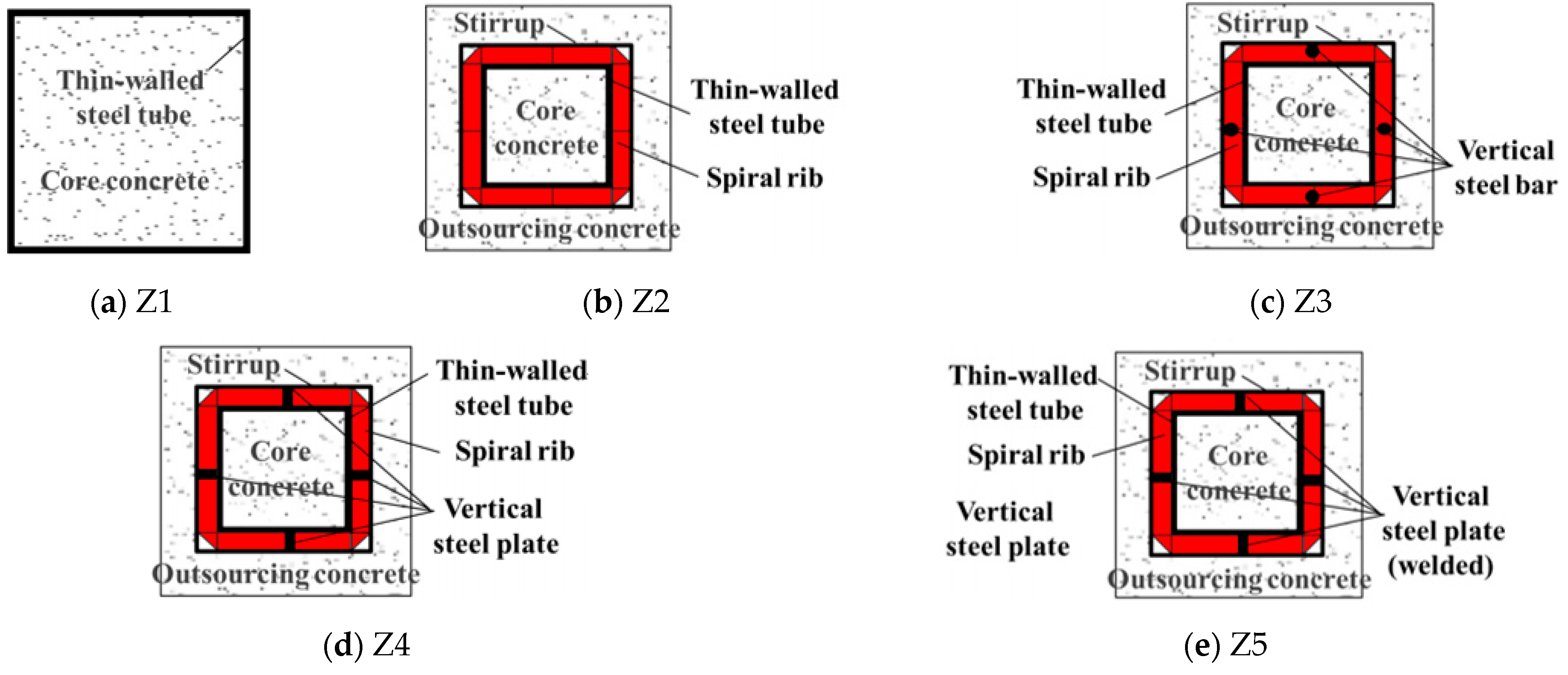
Figure 1. Schematic of concrete-filled tubular steel columns [26,27].
Buildings 14 02122 g001
Figure 2. Sections of concrete-filled steel tubular columns with different constraint forms [26,27].
Buildings 14 02122 g002
Figure 3. Test loading device [26,27].
Buildings 14 02122 g003
Figure 4. Failure form of specimen [26,27].
Buildings 14 02122 g004
Figure 5. Comparison of experimental curves [26,27].
Buildings 14 02122 g005
Figure 6. The stress model diagram of the specimen [26,27].
Buildings 14 02122 g006
Figure 7. Local buckling region of steel tube in composite column.
Buildings 14 02122 g007
Figure 8. Mechanical model of thin plate under compression, tension and shear.
Buildings 14 02122 g008
Figure 9. Rectangular thin plate coordinate system.
Buildings 14 02122 g009
Figure 10. The boundary curves between consecutive buckling modes for the biaxial loaded plate.
Buildings 14 02122 g010
Figure 11. Thin plate finite element model diagram.
Buildings 14 02122 g011
Figure 12. Each order buckling mode.
Buildings 14 02122 g012
Figure 13. Buckling mode of thin plate with S = 1.28 and β = −0.2.
Buildings 14 02122 g013
Figure 14. Buckling mode of thin plate with S = 1.52, β = −0.2.
Buildings 14 02122 g014
Figure 15. Buckling mode of thin plate with S = 1.79, β = −0.2.
Buildings 14 02122 g015
Figure 16. Buckling mode of thin plate with S = 2.13, β = −0.2.
Buildings 14 02122 g016
Figure 17. σx-γ curves under different load conditions.
Buildings 14 02122 g017
Figure 18. Load–displacement curve of the composite column under each parameter [26,27].
Buildings 14 02122 g018
Figure 19. Influence rule of each parameter on reinforcement coefficient of cladding concrete.
Buildings 14 02122 g019
Figure 20. Influence law of each parameter on strengthening coefficient of core concrete.
Buildings 14 02122 g020
Figure 21. ς and η relationship fitting curve.
Buildings 14 02122 g021
Table 1. Parameters of the specimen (unit: mm) [26,27].
Specimen NumberColumn
(H × Bt)
Steel Tube
(ds × ts)
Spiral Rib
(br × tr)
Steel Plate
(bp × tp)
Steel Bar
(ns)
Constraint Measures
Z11000 × 340340 × 1---None
Z21000 × 340220 × 130 × 3--Spiral rib
Z31000 × 340220 × 130 × 3-14Spiral-ribbed steel bar
Z41000 × 340220 × 130 × 330 × 5-Spiral-ribbed steel plate
Z51000 × 340220 × 130 × 330 × 5-Spiral-ribbed steel plate (weided)
Note: H is specimen height; Bt is specimen width; ds is steel tube width; ts is steel thickness; br is spiral rib width; tr is thickness of spiral rib; bp is vertical steel plate width; tp is vertical steel plate thickness; ns is diameter of vertical steel bar.
Table 2. Steel mechanical property index [26,27].
CategoryYield Strength/MPaUltimate Strength/MPaYield RatioElongation/%
Steel tube278.70388.930.7227.3%
Spiral rib256.94363.790.7125.7%
Steel plate252.65359.260.7022.7%
Steel bar462.95625.300.7424.6%
Table 3. Performance of concrete materials [26,27].
Strength GradeSpecimen Labelfcu,k/MPafck/MPaFc/MPaEc/GPa
C30134.623.127.324.7
233.822.626.724.4
333.522.426.524.3
Average34.022.726.824.5
Note: fcu,k is standard value of compressive strength of concrete cubes; fck is standard value of axial compressive strength of concrete; fc is design value of axial compressive strength of concrete; Ec is modulus of elasticity for concrete.
Table 4. Formula calculation results.
γSRk3k1σx/MPa
0.81.28−0.2563.454.44 49.30
1.21.28−0.2563.844.97 77.96
1.51.28−0.2563.134.08 87.15
2.01.28−0.2563.003.95 125.85
3.01.28−0.2562.913.91 517.47
4.01.28−0.2562.873.93 812.63
0.81.52−0.3042.974.61 51.21
1.21.52−0.3043.124.88 77.91
1.51.52−0.3042.774.36 93.05
2.01.52−0.3042.674.24 135.11
3.01.52−0.3042.624.24 561.83
4.01.52−0.3042.594.27 884.10
0.81.79−0.3582.575.02 55.80
1.21.79−0.3582.745.39 84.48
1.51.79−0.3582.444.83 103.12
2.01.79−0.3582.374.73 150.80
3.01.79−0.3582.344.76 630.12
4.01.79−0.3582.314.78 989.05
0.82.13−0.4262.196.16 68.43
1.22.13−0.4262.386.73 105.49
1.52.13−0.4262.126.02 128.68
2.02.13−0.4262.075.92 188.90
3.02.13−0.4262.055.96 789.15
4.02.13−0.4262.046.02 1245.01
Table 5. The first four order critical loads.
ModeEigenvalueCritical Buckling Load (MPa)
First mode296.9874.25
Second mode329.8882.47
Third mode542.30135.58
Fourth mode812.71203.18
Table 6. S = 1.28, β = −0.2 thin plate buckling stress.
γEigenvalueCritical Buckling Load (MPa)
0.8198.6849.67
1.2283.6870.92
1.5362.0590.51
2.0509.43127.36
3.02130.20532.55
4.03405.20851.30
Table 7. S = 1.52, β = −0.2 thin plate buckling stress.
γEigenvalueCritical Buckling Load (MPa)
0.8202.8350.71
1.2296.9874.25
1.5376.2694.07
2.0535.24133.81
3.02249.50562.38
4.03586.30896.58
Table 8. S = 1.79, β = −0.2 thin plate buckling stress.
γEigenvalueCritical Buckling Load (MPa)
0.8205.9851.50
1.2338.5684.64
1.5387.6296.91
2.0616.82154.21
3.02776.40694.10
4.04094.601023.65
Table 9. S = 2.13, β = −0.2 thin plate buckling stress.
γEigenvalueCritical Buckling Load (MPa)
0.8208.5052.13
1.2345.7386.43
1.5529.73132.43
2.0840.45210.11
3.02847.21423.6
4.04792.61198.15
Table 10. Comparison of simulated values (test values) and formula calculation results.
Specimen NumberBuckling Capacity/kNError Value/%
Test or SimulationFormula Calculation
Z32700.02560.0−5.2%
LX127,992.028,831.83.0%
LX226,302.027,406.74.2%
LX327,117.627,470.11.3%
LX424,889.723,645.2−5.0%
LX526,739.125,589.3−4.3%
LX627,736.028,679.13.4%
GH124,933.126,628.66.8%
GH225,798.925,102.3−2.7%
GH327,992.030,007.57.2%
GH428,033.728,314.11.0%
GH528,391.427,454.5−3.3%
LJ125,831.223,764.7−8.0%
LJ228,033.728,314.01.0%
LJ328,936.829,891.73.3%
LJ429,324.328,503.2−2.8%
GJ126,833.627,423.92.2%
GJ228,936.827,750.4−4.1%
GJ329,172.528,880.7−1.0%
GJ430,748.331,763.03.3%
GJ530,944.232,429.64.8%
Disclaimer/Publisher’s Note: The statements, opinions and data contained in all publications are solely those of the individual author(s) and contributor(s) and not of MDPI and/or the editor(s). MDPI and/or the editor(s) disclaim responsibility for any injury to people or property resulting from any ideas, methods, instructions or products referred to in the content.