Abstract
In this study, the corrosion properties of plasma-sprayed Al2O3 coating (APSS) with a topcoat of zirconium-based conversion coating (ZrCC) and organofunctional silane coating (3-glycidyloxypropyltrimethoxysilane; GPTMS) on carbon steel are investigated in detail. Additionally, the bond strength of plain steel bars coated with this system in normal strength concrete are newly tested. The APSS coating exhibits significant porosity, with unfavourable open pores limiting the barrier protection effect. In contrast, the surface roughness (Ra) significantly increases, improving the bond strength between steel bars and concrete. Such increase in carbon steel roughness improves bond strength in concrete. The synergic application of ZrCC and GPTMS topcoats significantly enhances the corrosion resistance of the base coat (inhibition effect). The character of the GPTMS coating increases the wettability of the APSS coating, which further positively contributes to bond strength between plain bars and concrete. It is demonstrated that when the ZrCC topcoat is applied without GPTMS, the corrosion resistance increases insignificantly and the surface wettability decreases, negatively affecting bond strength in comparison with carbon steel coated using an APSS base coat only.
1. Introduction
At present, the corrosion of concrete reinforcement is the most important issue limiting the service life of reinforced concrete structures [1,2]. Although the surface of conventional carbon steel reinforcement is protected by the natural alkalinity of the concrete pore solution, significant corrosion may develop mainly due to the carbonation of the concrete cover layer (the reduction of the pore solution pH by CO2 and NOx from the ambient atmosphere) and/or the ingress of chloride anions (the application of de-icing salts and seawater) [3,4,5,6,7]. The resulting voluminous corrosion products cause cracks in the cover layer, increasing the ingress of corrosion stimulants and significantly reducing the reinforcement bond strength in concrete [8,9]—see Figure 1.
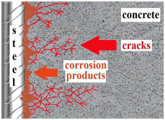
Figure 1.
Graphic model of surface corrosion of conventional concrete steel reinforcement with the formation of voluminous corrosion products and cracks in the concrete cover (reprinted from [2]).
The durability of reinforced concrete structures can be improved by increasing the density of the concrete cover layer (through a low w/c of the mix, the use of admixtures with pozzolanic effect, increasing a concrete class, etc.) [9,10], by the use of additives increasing the binding of chloride ions (nano-Al2O3 and carbon-based nanomaterials) [11], or through measures directly related to the corrosion protection of the reinforcement, e.g., the application of cathodic protection [12], corrosion inhibitors [13,14], or protective coatings [12]. Driven by economic reasons and based on long-term experience, epoxy and hot-dip galvanized coatings are preferred in the current construction practice. Non-porous epoxy coatings can significantly extend the service life of reinforced concrete structures (especially against chloride anions) [12,15,16]. However, it has been experimentally verified that the coating is not UV stable and reduces the bond strength of the reinforcement in concrete [17,18,19]. Also, the hot-dip galvanized coating can provide an extension of the service life of reinforced concrete structures [20,21,22]. However, in fresh concrete, the coating corrodes under hydrogen evolution, which reduces bond strength [23,24]. According to some studies, corrosion products based on CHZ (calcium hydroxyzincate dihydrate—Ca[Zn(OH)3]2·2H2O) may also adversely affect the bond strength of the reinforcement in concrete (pushing off the cement paste) [25]—see Figure 2. However, other studies suggested that these corrosion products significantly increased surface roughness and thus, in turn, could increase bond strength [26].
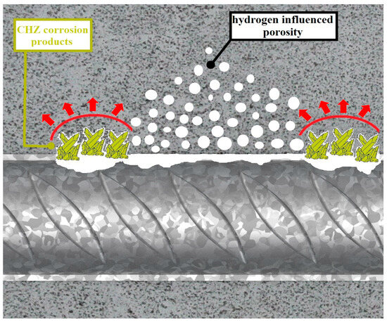
Figure 2.
Scheme of changes in ITZ due to the corrosion of the hot-dip galvanized coating in concrete (generation of hydrogen bubbles and precipitation of CHZ corrosion products—the figure takes into account the conclusions of article [25]).
The bond strength of reinforcement in concrete is an essential factor ensuring the load-bearing capacity of reinforced concrete structures [27,28,29]. The use of Al2O3-based coatings is associated with an increase in the hardness of the steel surface, its mechanical strength (resistance to abrasive wear), and also an increase in surface roughness. The use of plasma-sprayed Al2O3 coatings on the surface of conventional steel reinforcement may significantly improve the bond strength of reinforcement in concrete. However, the resulting coatings contain naturally open pores [30,31], and the sealing of these pores is crucial for corrosion protection. Organofunctional silanes may ensure perfect sealing and, at the same time, increase the bond strength of reinforced steel in concrete. This coating is used in the industry as an adhesive bridge between concrete and coating systems—usually epoxy-based [32,33]. The advantage for the application of organofunctional silanes to the Al2O3 (alumina) surface is primarily the more significant reactivity compared to the steel substrate, as is demonstrated in Figure 3 [34,35].
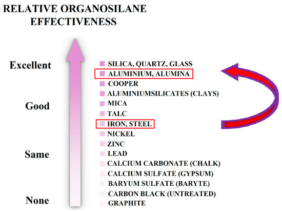
Figure 3.
Showing the difference in reactivity with organofunctional silane between steel and aluminium oxide (alumina—Al2O3)—reprinted from [35].
The application of a single layer of mono-silanes increases the corrosion resistance of the underlying metal [36,37]. However, higher resistances have been achieved when using multiple layers [38]. In this context, bis-silanes characterized by two alkoxysilane groups (at both ends of the molecule) have been successfully and most widely applied. Bis-silanes form a more homogeneous coating with higher thickness. Coatings are mainly based on:
- amino-silane (bis-[3-(triethoxysilyl)propyl]amine), increasing the hydrophilicity of the surface;
- tetrasulfide-silane (bis-[3-(triethoxysilyl)propyl]tetrasulfide), acting hydrophobically [39,40].
See a representation of the molecules of both silanes in Figure 4.
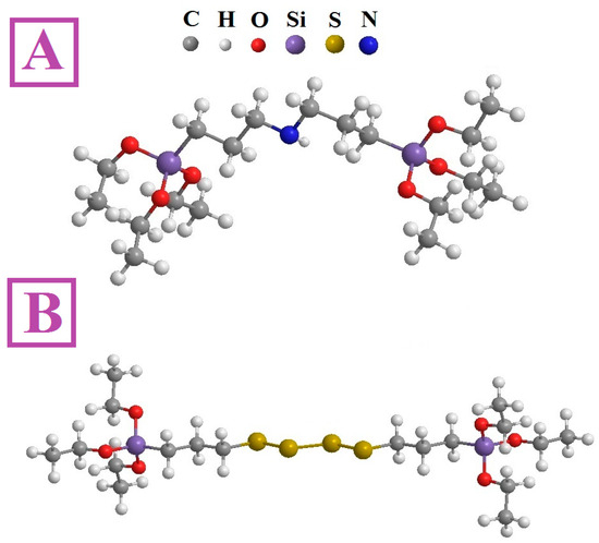
Figure 4.
Representation of the two most commonly tested bis-silanes in metal surface treatment: (A) bis-aminosilane and (B) bis-tetrasulfidesilane; reprinted from [40].
The application of organofunctional silanes in the form of coatings is based on the hydrolysis of alkoxy groups in order to form the corresponding silanols, and the subsequent adsorption to the surface via hydrogen bridges with free OH groups on the surface. Usually, the application of organofunctional silanes on the surface is associated with the final step of drying at elevated temperatures. During this step, a crosslinking reaction of individual molecules occurs—this is called condensation and polymerization of the organofunctional silane coating [36,41,42,43]. The general mechanism of organofunctional coating formation is shown in Figure 5.
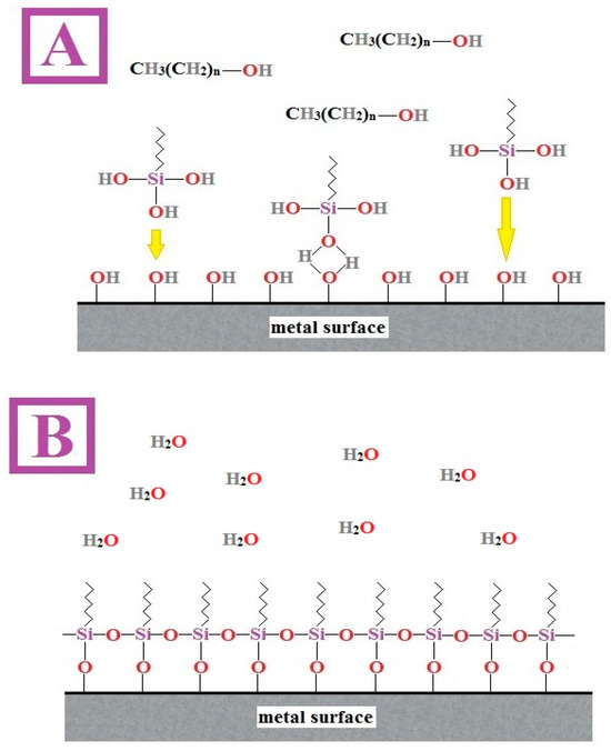
Figure 5.
Illustration of the mechanism of adsorption of organofunctional silane molecules onto a metal surface to form hydrogen bridges (A), and subsequent condensation with polymerization (B) to form a continuous coating—reprinted from [36].
The first goal of this study is to assess the effectiveness of the application of mono-silane (organofunctional silane) 3-glycidyloxypropyltrimethoxysilane (GPTMS—see Figure 6) in sealing open pores in plasma-sprayed Al2O3 coating on steel reinforcement surfaces. Although organofunctional silanes have been marginally tested before in sealing pores in ceramic coatings, the commercially available organofunctional silane GPTMS has never been tested. The application advantage for the coatings industry in using this organofunctional silane is based on the availability of the formulation in a pre-hydrolysed and oligomerized form. This formulation is also significantly more affordable than more expansive bis-silanes. However, the effect of organofunctional silanes on reinforcement bond strength has not been investigated either. Considering that the theoretical basis suggests (see Figure 3—higher reactivity with silica phase) a favourable effect of organofunctional silanes on bond strength, the second goal of this study is to verify this hypothesis by means of an experimental campaign.
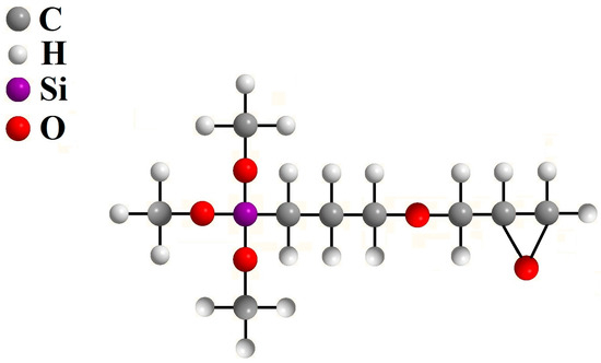
Figure 6.
Structural formula of applied organofunctional silane (GPTMS) in oligomerized form and pre-hydrolysed for direct application to the steel surface with a plasma-sprayed coating of Al2O3—reprinted from [35].
2. Materials and Methods
The plasma-sprayed Al2O3 (APSS) coating was applied to each steel sample before the application of further coatings, such as the zirconium-based conversion coating (ZrCC) and the organofunctional silane coating (GPTMS). Flat carbon steel samples (100 mm × 20 mm × 2 mm) were used to identify the corrosion properties of individual coatings. The carbon steel sample composition is detailed in Table 1. Plain carbon steel bars (l = 1000 mm, d = 10 mm) were used to quantify the bond strength of coated steel in concrete. The sample composition of the plain steel bars is detailed in Table 2.

Table 1.
Composition of flat steel samples (GD-OES).

Table 2.
Composition of plain bar steel 10216 (GD-OES).
For bond strength tests, a test cube (a = 150 mm) was made, with plain bars positioned into the centre of concrete samples using an internal wooden rhomboid at the bottom of the mould and an external clamp (made from polyacrylate using 3D printing—Prusa 3D printer i3MK3S+ (Prusa Research, Prague, Czech Republic)) at the top of the form—see Figure 7. In total, 28 cube moulds were prepared including 4 duplicates of 7 plain steel bar samples. Further, 5 cube moulds were prepared without plain steel bars for the concrete strength test (Figure 8). Portland cement CEM I 42.5 R (Českomoravský cement, a.s., Mokrá—Horákov, Czech Republic) was used to produce the cube moulds, and its composition is shown in Table 3. The normal-strength concrete (NSC) was prepared according to the protocol in Table 4. The concrete batch was homogenized for 10 min with the concrete mixer GIFOS MB80 at a speed rotation of 30 rotations per minute. The cube mould filling was performed step-wise in 3 layers, with each layer being compacted for 5 min with a hand-vibrating device (Eibenstock EBR 125.1, Elektrowerkzeuge GmbH Eibenstock, Eibentsock, Germany). All samples were cured in medium humidity (65% RH, 21 ± 1 °C) for 24 h. After the curing period, they were fully submerged in distilled water (20.5 ± 1 °C) for 27 days.
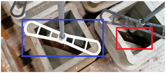
Figure 7.
Images of plain steel bars centred at the centre of cube forms. The red annotation shows the bottom wooden insert. The blue annotation shows the top 3D-printed polyacrylate clamps.
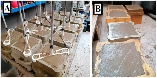
Figure 8.
Image (A) shows 28 cube forms with plain steel bars for the bond strength test. Image (B) shows 5 samples without plain steel bars for the concrete compressive cubic strength test.

Table 3.
Cement composition guaranteed by the producer (CEM I 42.5 R).

Table 4.
Content by m3 of concrete for cubic samples used for pull-out test.
A total of 21 plain steel bars and 12 flat steel samples were plasma-sprayed with Al2O3 coatings (APSS), as shown in Figure 9. Medium-purity (95.5 wt.%) alumina oxide powder AH 240 was applied (due to the relatively low price of the powder) using a hybrid water-stabilized plasma torch WSP-H 500 (The Czech Academy of Sciences—Institute of Plasma Physics). Before the alumina oxide application, the steel sample surface was sandblasted with corundum abrasive. The final surface roughness was 5.5 µm (Ra). The plasma torch output was 150 kW, generated by a direct current of 500 A. The resulting electric arch between the tungsten cathode and the inner cooled rotational anode had an outlet temperature of 25 000 K, and the flow speed was 7000 m·s−1. The plasma enthalpy was approximately 300 MJ·kg−1. The Al2O3 powder was fed to the plasma jet at a feeding distance of 75 mm, and the spray distance was 450 mm. The chosen distances promote the formation of a harsh coating with higher porosity, reducing the required amount of Al2O3. The coating application was performed in two layers, resulting in a total thickness of 220 µm. Between layer depositions, the steel surface was cooled with pressurized air to reach a temperature of 110 °C.
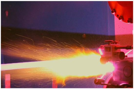
Figure 9.
Application of plasma-sprayed Al2O3 coating on the surface of a plain steel bar with a WSP-H 500 torch.
Furthermore, some samples were coated with a zirconium-based conversion coating (ZrCC) as a topcoat. In total, 7 plain steel bars and 4 flat steel samples were coated with ZrCC only, and the other 7 plain steel bars and 4 flat steel samples were coated with a combination of ZrCC and organofunctional silane coatings (3-glycidyloxypropyltrimethoxysilane, GPTMS). The coating was deposited by dipping the samples in commercially available reagents. The ZrCC bath contained (NH4)2ZrF6 a (NH4)3PO4 diluted in distilled water, while the GPTMS bath was based on a pre-hydrolysed and oligomerized form of 3-glycidyloxypropyltrimethoxysilane diluted in distilled water. The ZrCC-coated samples were extensively washed. The ZrCC- and GPTMS-coated samples were cured under the conditions described in Table 5. The key abbreviations are explained in Table 6.

Table 5.
Coating conditions of different treatments.

Table 6.
Abbreviation table.
The steel samples with Al2O3 coating were cut transversally and polished with an automatic polishing machine (Struers LaboPol 5, Struers GmbH, Willich, Germany), polishing paper with a grit size of P60—P2400, and diamond polishing paste. Sample cooling and washing were performed with ethanol (98 wt.%). The plasma-sprayed Al2O3-coated steel transversally cut samples were imaged with an electron microscope JEOL JSM IT-200 (JEOL Ltd., Tokyo, Japan).
The composition of flat steel APSS sample coating was analysed using X-ray diffraction (Malvern Panalytical, Malvern Panalytical V. B., Almelo, The Netherlands) with CuKα radiation over the angular range of 5–90°. The porosity of samples was analysed using a mercury porosimeter AutoPore IV—Micromeritics. In total, 5 samples were measured, and the total measured area was 0.5 cm2.
Electrochemical tests included corrosion potential measurement (Ecorr) and polarisation resistance (Rp) measurements for 162 h. The tests were carried out on 4 samples and measured every hour. A silver/silver chloride electrode (SSCE) served as the reference electrode. The test was performed in a simulated concrete pore solution (SCPS see Table 6) with the addition of chloride anions (3.5 wt.% NaCl). The SCPS was prepared by mixing CaO (p.a.) and NaCl (p.a.) in distilled water for 3 h (21.0 ± 1 °C) until a saturated solution was achieved. The final pH was buffered to 13.0 with KOH (p.a.). After the assembly of the setup and the filling of cells with simulated concrete pore solution, the start of measurement was delayed for 15 min before starting the sequential measurement of Ecorr and RP (the so-called Rp/Ecorr trend). The total exposed area of the samples was 4.5 cm2. The polarization resistance value was evaluated as the linear coefficient of current density and potential in the vicinity of Ecorr (polarization range: −20 to +20 mV; scan rate: 0.1 mV·s−1). The electrochemical impedance spectra were measured in the frequency range from 10 kHz to 10 mHz, with 10 mV/Ecorr AC amplitude within a 14 h period. The measurement was performed in a three-electrode setup in a PTFE press-on cell of cylindrical shape (the total area of the sample was always 4.5 cm2). Glassy carbon rods were used as counter electrodes placed on the axis of the capillary outlet. Electrochemical measurements were performed using the Electrochemical Multiplexer ECM 8 (which allows the measurement of 4 parallel samples), with the Reference 600 potentiostat (Gamry Instruments, Warminster, PA, USA).
The roughness of plain uncoated steel (US) bars, APSS, and GPTMS samples was measured before the bond strength test. Each of the 5 randomly selected samples was measured in 3 lengthwise tracks with the Mitutoyo SJ-400 device (Mitutoyo, Kawasaki, Japan). The wettability of flat- coated steel samples (APSS, ZrCC, and GPTMS) was measured with the SEE System (ADVEX Instruments, Brno, Czech Republic) goniometer, using the sessile drop technique with distilled water. The measurements were carried out on a total of 4 parallel samples (each sample was measured at 3 different locations).
The pull-out test, as described by RILEM RC6 [44] and ASTM C234-91a [45], was performed to assess bond strength. The bond strength of coated steel bars with concrete compared to uncoated plain steel bars was assessed by means of a bond stress slip. The slip was measured using an LVDT sensor (Micro-Epsilon Messtechnik GmbH, Ortenburg, Germany) located at the opposite end of the loaded steel bar sample. The anchorage length was given by the concrete cube sample and plastic tube separation, as shown in Figure 10. The pull-out test was performed using the 100 kN TIRA test machine (Figure 11). The displacement of the unloaded end of the plain bar controlled the test. A constant loading rate of 0.005 mm·s−1 was applied. The test was terminated after reaching a slip of 2.0 mm.
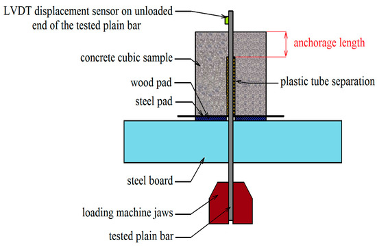
Figure 10.
Experimental setup of pull-out bond strength test between a plain bar and normal strength concrete—anchorage length is in red.
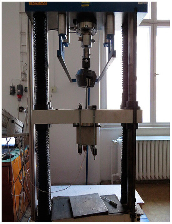
Figure 11.
A real pull-out test implemented on a load machine.
3. Results and Discussion
For easier orientation in the text of this paper, the Results and Discussion section is divided into three subsections.
In Section 3.1, the APSS coating is described (without ZrCC and GPTMS coatings) for the average thickness on the surfaces of steel and plain bar samples, and the porosity is visually evaluated by means of SEM and also mercury porosimetry. This subsection discusses the results of the roughness of the APSS coating on the surface of the plain bars, and the phase composition of the coating using XRD is discussed. In Section 3.2, the corrosion resistance of flat steel specimens with the APSS coating and with the ZrCC and GPTMS topcoats is evaluated. Corrosion resistance testing was performed on flat steel samples in simulated concrete pore solution (SCPS) via the Ecorr/Rp trend and EIS characteristics. Finally, in Section 3.3, the bond strength of plain bars with and without APSS coating (and also the effect of coating ZrCC and GPTMS) in normal-strength concrete was evaluated using the pull-out test. In this subsection, the surface contact angle of flat steel specimens with APSS coatings is also evaluated, as is the influence of the presence of ZrCC and GPTMS.
3.1. Analysis of the APSS Coating
Figure 12 shows the SEM image of the outer surface of the plasma-sprayed Al2O3 coating (APSS) on the surface of a flat steel sample. The APSS coating has a typical splat structure with spherical grains with a most common diameter of 30–50 µm [46,47]. Cracks and smaller pores are visible between the outer splats. However, more significant pores are seen at the splat boundaries between the individual spherical splats. The cross-section of the APSS coating (Figure 13) reveals the presence of typical semi-molten and unmolten particles with a typical porosity of 2–5 µm. However, this figure also shows continuous porosity greater than 5 µm with cavern formation in the coating [48,49]. Through capillary phenomena, the filling of these caverns with outer electrolyte can occur. However, Figure 13 also shows the typical presence of semi-molten and over-molten particles of oxide impurities in the used AH 240 powder [49,50]. Considering the expected presence mainly of α-Al2O3 in the APSS coating on steel, an open porosity of approximately 4.4% can be expected [51]. However, porosity measurements using mercury porosimetry (see Figure 14) on flat samples showed the very frequent presence of pores of 5 µm pore diameter, but also pores with a diameter significantly larger than 10 µm. The total porosity of the flat samples was determined to be around 0.15% on average.
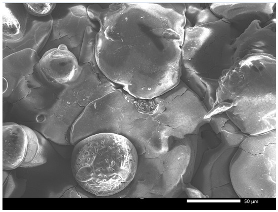
Figure 12.
Surface splat structure of plasma-sprayed Al2O3 coating on flat steel samples—detail vision.
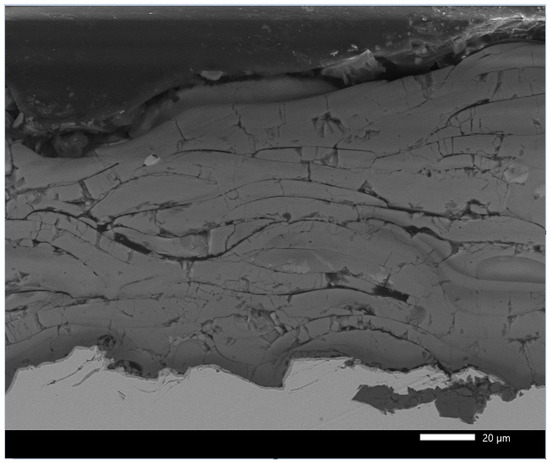
Figure 13.
Detailed demonstration of the natural open porosity of the plasma-sprayed Al2O3 coating on flat steel samples.
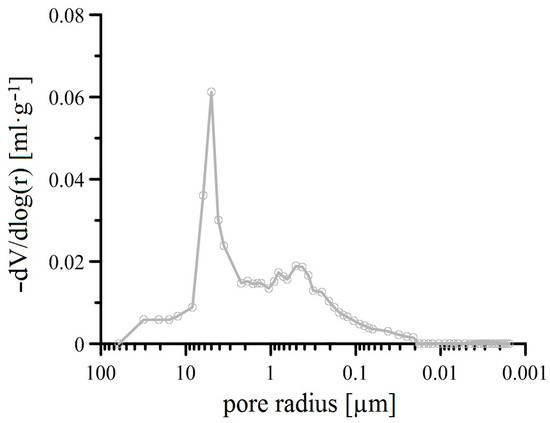
Figure 14.
Pore size distribution of plasma-sprayed Al2O3 (APSS) coating on flat steel samples (overview; curves—mean values).
Coating thickness measurements were performed using cross-sectional SEM images (30 measurements from each sample type, i.e., flat steel samples and plain bars). On the flat samples, the average coating thickness was 217 ± 14 µm. On the circular surface of the plain bars (probably due to the more complex surface geometry), a lower coating thickness of 208 ± 11 µm was found.
Figure 15 shows the results of the measurement of APSS coating phase composition using X-ray diffraction (the thickness of the coating prevents the detection of the underlying steel). From the results, it is clear that the coating is formed only through the modification of Al2O3. The impurity content of the powder used is only influenced by the presence of the different Al2O3 modifications. The α-Al2O3 phase is only represented by approximately 22 wt.%, the γ/δ-phase is the most represented (approximately 70 wt.%), and the δ-phase is the least represented (approximately 8 wt.%). A similar APSS coating composition on carbon steel was previously achieved using torch WSP-H 500 [52]. The obscuration of these phases and the relatively higher impurity content condition the observed porosity of the APSS coating.
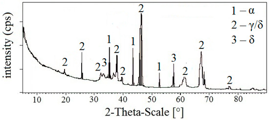
Figure 15.
X-ray analysis of plasma-sprayed Al2O3 coating on steel (detection of the modification of Al2O3 phases only).
A comparison of the roughness of plain steel bar samples without coating (US), with APSS coating only, and finally APSS with GPTMS (topcoat) is shown in Figure 16. It is evident that the application of plasma-sprayed Al2O3 coatings increases the surface roughness (Ra) of the plain steel bars by approximately a factor of 10, and it is also evident that the thickness of the GPTMS coating does not significantly reduce the natural porosity of the APSS coating.
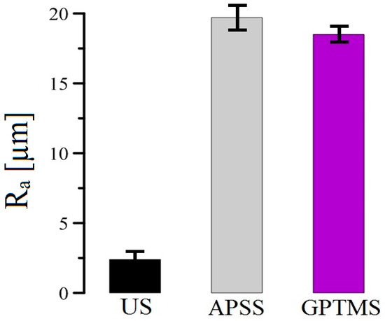
Figure 16.
Bar chart of coating roughness results for plain steel bars.
3.2. Corrosion Properties of Coated Flat Steel Samples in SCPS
The hydrolysis of organofunctional silanes in aqueous solutions (or in aqueous solutions with base alcohols) leads to the formation of the corresponding silanols (the hydrolysis is shown by the system of subsequent equilibrium reactions in Equation (1)). Through free OH groups, these silanols can adsorb to the metal surface, and by means of subsequent condensation and polymerization (usually at elevated temperatures), they can form a network (cross-linking) of Si-O-Si bonds (see Equations (2) and (3)) and create a continuous coating [41,53,54,55].
However, adsorption on the carbon steel surface is quite difficult for silanols, and the number of free OH groups on the metal surface plays an important role (see Figure 5). Neither the clean metal surface nor the conventional steel corrosion products (polymorphs of FeO(OH)) are suitable surfaces for the application of organofunctional silanes [56,57]. For this reason, it is very often recommended to expose the steel to an alkaline environment (pH ideally close to the isoelectric point, i.e., 9.5) [57] or to pickle the surface in sulfuric acid [58,59]. Sufficient amounts of OH groups for good adhesion to organofunctional silane can provide conversion coatings; in this respect, CeIII-based coatings [60,61,62], phosphate coatings [63], and zirconium-based coatings [64,65], among others, have been successfully tested. The additions of Zr(NO3)4 directly to silane baths enhance the barrier protective effects of the resulting coating [66]. In engineering practice, zirconium (ZrCC)- and titanium (TiCC)-based conversion coatings are very often used in painted steel technology (often in combination) as a modern phosphate-free and chromate-free (CrVI)) process [67]. Based on these facts, the application of ZrCC was preferred over other conversion coatings in this work. It is assumed that during the coating of APSS with ZrCC, the precipitation of ZrO2·2H2O and Zr(HPO4)2 (the phosphate formed is ultimately minor) occurs according to reactions (4)–(6) in the open pores of APSS on the steel surface. The conversion coating thus formed on the steel surface significantly improves the adhesion properties of organofunctional silane (GPTMS). It is further established that GPTMS adsorbs very readily to the APSS surface (even to the inner surface of open pores in the APSS coating) to form a continuous coating. These assumptions are shown in Figure 17.
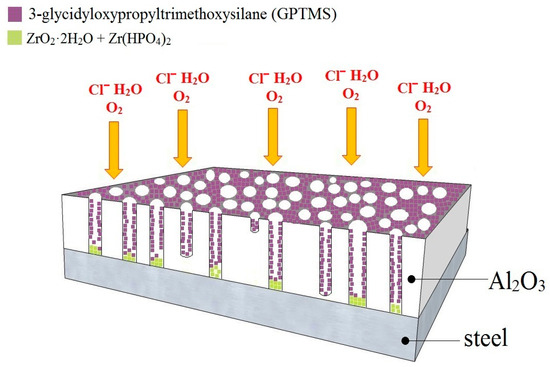
Figure 17.
Schematic of the surface occupation of steel sample with plasma-sprayed Al2O3 coating by ZrCC and GPTMS (displaying also the expected surface occupation of open pores in APSS).
Figure 18 shows the Ecorr and Rp (Ecorr/Rp) trend for the samples of the plasma-sprayed Al2O3 coating without additional surface treatment (APSS), then the APSS coating with the zirconium conversion coating (ZrCC), and finally with the application of hydrolysed GPTMS solution. From the measurement results, it is clear that APSS does not provide significant protection to the underlying steel due to its open porosity (the existence of pores larger than 10 µm in diameter; see Figure 14). The usual passive layer on the steel surface (the effect of the alkaline environment) does not form because of the presence of Cl− in SCPS. Since the Rp value for the APSS samples is around 1.0 Ω·m2 throughout the exposure time, SCPS reaches the underlying steel through open porosity very quickly. The resulting corrosion products of the steel would subsequently very easily break down the integrity of the APSS coating if applied to the surface of the reinforcement in concrete. From this point of view, this coating cannot be considered suitable for application to the surface of concrete reinforcement. The results of the Ecorr/Rp trend measurements further show that the protective effect of only the ZrCC conversion coating surface treatment (precipitation on the steel surface in open pores; see Figure 17) is quite negligible (the usual thickness of this surface treatment is only about 300 nm [68,69]). In this case, the measured Rp values do not differ throughout the exposure time from those measured for the APSS samples. It is possible to consider that chloride anions very quickly disrupt the continuity of the conversion coating, or with the ZrCC bath coating process. The coating fails to form on the steel surface in the open pores (for this type of samples, a short exposure time may be involved). A significant difference in the time dependence of Ecorr and Rp was measured for the APSS samples with the ZrCC and the GPTMS coating. It is evident, that in contrast to the application of ZrCC alone, organofunctional silane significantly affects the corrosion behaviour of APSS samples. Although the barrier protective effect of the coating is insignificant (low Rp values at the beginning of the exposure, only two times higher than in samples without GPTMS), the Rp values already increase sharply after about 15 h. This trend is steady, and apparently (although significantly slower than at the beginning of exposure) would exceed the period of the test. In this case, the Rp values at the end of the exposure are approximately six times higher than those for the APSS and ZrCC samples. It can be expected that the dissolution of the organofunctional silane coating and the sealing of the pores in the plasma-sprayed Al2O3 coatings occur in SCPS during exposure. It can also be expected that the precipitation of insoluble silicon compounds occurs directly on the steel surface (exposed steel surface in open pores).
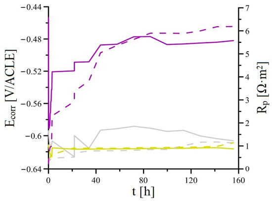
Figure 18.
Time dependency of Ecorr and Rp for four parallel samples in simulated concrete pore solutions (overview; curves—mean values).
The measured impedance spectra (Bode plot: log Zmod vs. log frequency and phase angle vs. log frequency) with equivalent circuits used for its fitting are shown in Figure 19 (APSS coating only), Figure 20 (APSS coating with ZrCC), and finally Figure 21 (APSS coating with ZrCC and GPTMS). In the equivalent circuits (ECs), Rel is solution resistance, and R1 and CPE1 represent pore solution resistance and Al2O3 layer capacity, respectively. R2 and CPE2 represent phase boundary steel-pore solution. R3 and CPE3 are associated with the high-frequency region and represent the influence of GPTMS. The used ECs are in the good agreement with the proposed ZrCC and GPTMS mechanism stated in Figure 17. The results of the specific resistances (R1 to R3) after 12 h, 72 h, and finally 168 h of exposure are plotted in Figure 22. The charge transfer resistance (R2) for all three types of samples is the key to the evaluation of the corrosion process. There was a gradual increase during the exposure for the APSS samples, indicating a slight stabilization of the passive layer due to the alkaline environment (the protective effect of OH− anions in SCPS is more significant than the stimulating effect of Cl−). In the case of samples with ZrCC addition, the situation was similar; there was only a slight increase in the charge transfer resistance (R2), probably caused by the inhibition effect. There was a significant increase in R2 in the case of GPTMS samples. This again indicates the inhibition of corrosion damage to steel by molecules released from the organofunctional silane coating (adsorption inhibition mechanism). The resistance R1 (pore resistance) in the case of APSS decreased slightly during the exposure; this could be due to the increasing concentration of ions in the pores. In the case of the ZrCC samples, there was a slight increase in R1 compared to APSS, indicating lower conductivity. For the GPTMS samples, an equivalent circuit with one extra R-C element (R3, CPE3) was used. This element represents the top layer of the organosilane, which can form molecules large enough to partially block open pores up to 10 μm in size. Both R1 and R3 increased slightly during exposure, which may indicate the formation of larger molecules that subsequently increased surface and pore blockage.
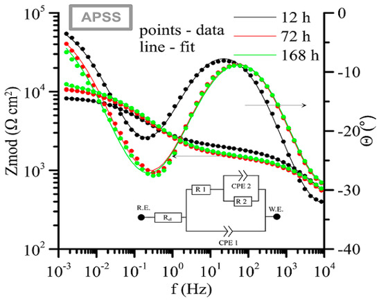
Figure 19.
Time-dependent impedance spectra for APSS only coating (Bode plot: log Zmod vs. log frequency and phase angle vs. log frequency).
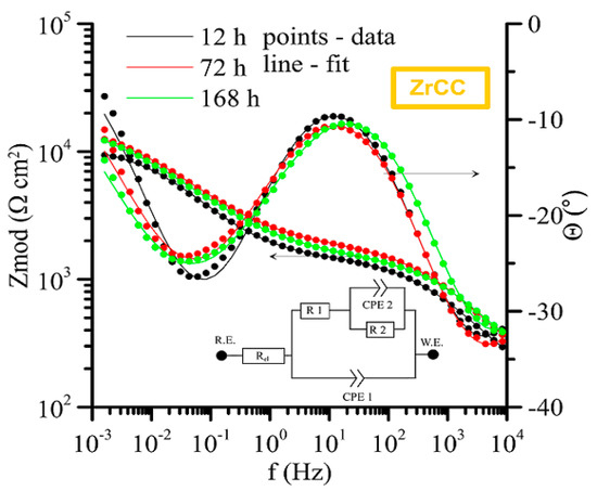
Figure 20.
Time-dependent impedance spectra for APSS and ZrCC coating (Bode plot: log Zmod vs. log frequency and phase angle vs. log frequency).
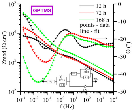
Figure 21.
Time-dependent impedance spectra for APSS + ZrCC and GPTMS coating (Bode plot: log Zmod vs. log frequency and phase angle vs. log frequency).
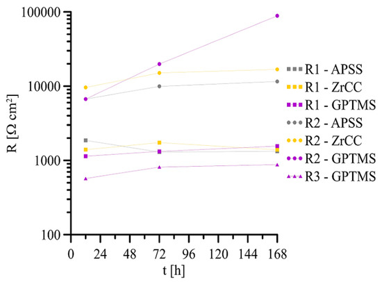
Figure 22.
Point evaluation of R1–R3 (t) EIS spectra for all coated samples in SCPS.
Based on the above, a model of the predicted protective effect of GPTMS against the corrosion of the underlying steel coated with plasma-sprayed Al2O3 coating can be proposed; see Figure 23. It is clear from the literature that in the case of exposure to the silane coating in a strongly alkaline environment, the dissolution of the silanes occurs to form finely dispersed SiO2 particles (and the formation of H2O or the corresponding simple alcohols) [36,37,70,71,72]. The SiO2 particles can converge to SiO32− due to the strongly alkaline environment, as seen in reaction (7). This anion can diffuse and/or migrate (due to the presence of Fe2+/Fe3+ formed by the anodic corrosion process at the steel surface) to the steel surface in open pores and block the charge exchange reaction during the corrosion process (formation of a continuous layer of CaSiO3 and/or FeSiO3).
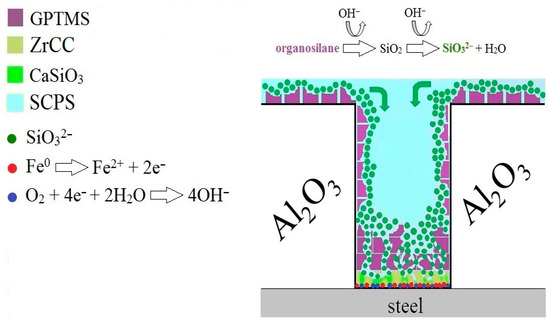
Figure 23.
Proposed mechanism of protection of the steel surface in the case of the application of organofunctional silane coating (GPTMS) on the surface of plasma-sprayed Al2O3 coating (APSS).
Already amorphous SiO2 particles may be able to effectively block the access of the electrolyte to the steel substrate in pores with smaller pore diameters. Regarding the inhibition of the corrosion process, it is necessary to discuss the mobility of Cl− versus SiO32− anions. Although there are very few relevant data on the mobility of SiO32− ions (low stability and high reactivity), it can be concluded that the mobility of chloride anions will be higher (higher diffusion coefficient and lower ion radius) than that of SiO32− anions [73,74,75]. However, the higher concentration of SiO32− ions in the Al2O3 coating pores in the early stages of exposure may play an essential role in rapidly inhibiting the corrosion process. From this point of view, the degree of occupation of the steel surface in the open pores by the applied organofunctional silane may also be substantial.
3.3. Bond Strength of Coated Plain Bar Steel Samples in Concrete
In the case of coated concrete reinforcement, it is necessary to verify the effect of the coating (its mechanical properties, surface roughness, surface contact angle, and possible corrosion in the concrete) on bond strength in concrete [24,25,76]. The bond strength of the reinforcement in concrete fundamentally influences the load-bearing capacity of the structure; a gradual decrease in the bond strength of the reinforcement in the concrete due to the corrosion damage of the steel surface can lead to collapse [28,29,77].
The roughness of the APSS coating is significantly higher than that of uncoated plain bars (see Section 3.1 and Figure 16) and is not significantly affected by the GPTMS coating. Thus, it is very likely that the increased roughness of APSS specimens will provide a significant increase in the bond strength of plain bars in concrete [25,76]. The surface contact angle is also important for the bond strength of the coated reinforcement in concrete. A good surface wettability of the coated concrete reinforcement ensures the perfect coverage of the surface with cement paste (the occupation of the surface by portlandite—Ca(OH)2 crystals), which results in a higher bond strength [25,78,79]. The low surface wettability (high surface contact angle) of epoxy coatings results in a lower bond strength of the coated reinforcement in concrete [17,80,81]. For these reasons, the effect of the different surface treatments (APSS without topcoat, ZrCC, and GPTMS) on the steel surface contact angle was verified, and the results are shown in Figure 24 and subsequently in the bar chart in Figure 25. From the results, it is clear that the contact angle for the APSS sample surface (without topcoat) is approximately 36°, and the subsequent surface treatment via ZrCC increases the wetting angle (increases the surface hydrophobicity) to a wetting angle value of approximately 61° (the reason for this may be the formation of specific ZrF62−-rich Al-rich jagged structures, giving the surface a lotus flower effect [82]). If the topcoat is composed of ZrCC and GPTMS, the surface hydrophilicity increases very significantly (the wetting angle is 0°). It is evident that GPTMS can significantly cover the surface of the plasma-sprayed Al2O3 coating and avoid the influence of ZrCC on the intrinsic wettability of the surface. A prior application of ZrCC is not strictly necessary to apply GPTMS to the APSS effectively. The reason for the increase in the wettability of the Al2O3 surface is the presence of OH groups from the open oxirane ring of 3-glycidyloxypropyltrimethoxysilane [83,84]. The surface Al2O3 plays a significant role in the hydrophilic properties of GPTMS—hence the considerable level of compatibility of the two solids.
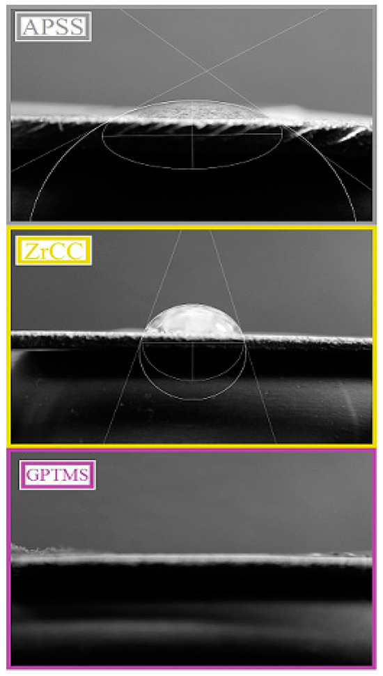
Figure 24.
The surface contact angle for each type of coating.
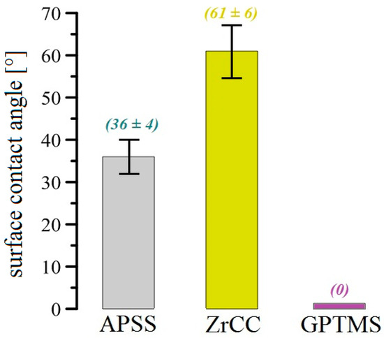
Figure 25.
Bar chart showing the surface contact angle measurements for all coatings (see Figure 24).
Figure 26 and Figure 27 show the results of the bond strength tests of plain steel bars in concrete of the C30/37 strength class (the average cube strength of the concrete was 47.7 ± 2.2 MPa). Figure 26 shows the curves (mean values) of bond stress versus slip, and Figure 27 shows a bar chart reflecting the statistically evaluated ultimate bond strength and slip results for each coated plain bar specimen.
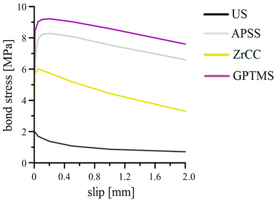
Figure 26.
Results of pull-out tests (overview; curves—mean values).
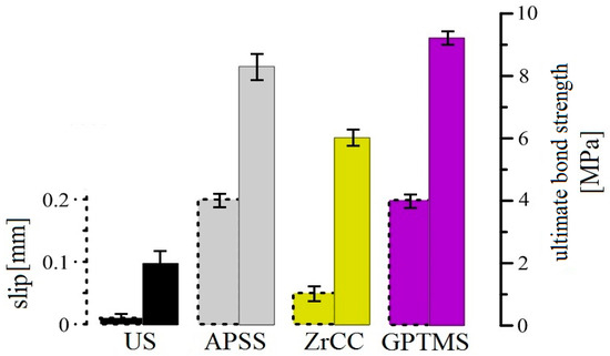
Figure 27.
Summary bar chart of bond strength and load–displacement results from Figure 26.
If the bond strength is tested on plain bars, then the overall bond force (Tc,i—see Equation (8)) cannot be influenced by the force of the mechanical resistance of the specific concrete cover layer (fσ). These facts are described by Equations (9) and (10), and the individual variables of these equations are summarized in Table 7. The contact area of the test plain bars with the concrete is determined only by the total area of the bar body (Ab) and is not affected by the total area of the bar ribs (Ar) [24,25,76,85,86].

Table 7.
Description of individual variables from Equation (8).
Although plain bar steel is rarely used as a concrete reinforcement (rather, for prefabricated parts, mostly ribbed steel reinforcement is used—for example, B500B), bond strength testing (pull-out test or beam test) using plain bars can very sensitively take into account the influence of the coating used on bond strength in concrete (the test factors are the complete adhesion of cement paste force fad and friction force ff). If the bond strength of the B500B reinforcement with concrete is tested, then the results of Tc,i are influenced by the mechanical properties of the concrete at the reinforcement/concrete phase interface.
The results of the APSS bond strength tests (with and without topcoat) indicate that the increase in the roughness of the plain bar in the case of the application of plasma-sprayed Al2O3 coating by a factor of approximately 10 results in an increase of the ultimate bond strength in concrete by a factor of more than 4 (increase in the effect of the ff factor). However, the influence of wettability on the ultimate bond strength is also evident (surface wettability is influenced by the fad factor). When only ZrCC was applied to the plasma-sprayed Al2O3 coating, the surface hydrophobicity increased and the surface contact angle increased by approximately 70%, resulting in a decrease in ultimate bond strength of approximately 30%compared to APSS (without topcoat). On the contrary, the increase in surface wettability when GPTMS was applied not only eliminated the negative effect of the ZrCC coating, but it also increased the ultimate bond strength of the plasma-sprayed Al2O3 coating by approximately 10%. Through the bond strength tests, it was verified that the applying of any coating (APSS or APSS with topcoats) prolongs the slip of plain bars. The gradual destruction of the top layer of plasma-sprayed Al2O3 coatings occurs in the case of APSS (cohesion breaking in the coating), which has a lower adhesion to the core of the APSS coating (the adhesion of the top layer of plasma-sprayed coating may be lower due to the increasing thermal insulation properties of the surface). The application of ZrCC can disrupt the non-cohesive top layer of Al2O3 through the presence of free F− anions in the coating (Equation (4)), which can be removed during the formation of the concrete cube samples prior to bond strength testing using the pull-out test. Therefore, the slip for ZrCC specimens may be lower than that for APSS specimens without a topcoat. However, the reduction in bond strength can also be caused by partial displacement between the two layers of the APSS coating. Increasing the wettability of the topcoat through the application of GPTMS increases the ultimate bond strength and the slip value. In this case, the disturbance of the topcoat layer of organofunctional silane due to the formed alkaline concrete pore solution of concrete during the preparation of specimens for bond strength testing can be discussed.
In general, it can be summarized that applying an APSS coating significantly increases the ultimate bond strength (the effect of increase in surface roughness), and the subsequent application of organofunctional silane in the form of GPTMS provides a further increase in ultimate bond strength. The effective necessity of applying ZrCC before applying GPTMS is not evident from the bond strength testing results. The sufficient adhesion and compatibility of organofunctional silane with Al2O3 have been previously demonstrated [34,35,87,88,89]. However, coating the concrete steel reinforcement of concrete with APSS and subsequently with, e.g., GPTMS increases the slip in the bond strength testing, i.e., even small shear forces can slightly displace the reinforcement and stimulate crack formation in the structure, which may reduce its overall load-bearing capacity. Structures containing such coated reinforcement may exhibit a higher sensitivity to, for example, cyclic loads.
4. Conclusions
This paper describes the effect of the plasma-sprayed Al2O3 coating (APSS—core coating) on the corrosion behaviour and bond strength of plain steel bars in concrete. In order to increase the corrosion resistance of the APSS porous coating, other surface treatments (topcoats) were tested, namely, zirconium-based conversion coatings (ZrCC) and a combination of ZrCC and organofunctional silane (3-glycidyloxypropyltrimethoxysilane)—GPTMS.
The most important findings of this study can be summarized as follows:
- The core coating (APSS) exhibited significant adhesion to the steel surface and increased the surface roughness compared to the uncoated plain bars.
- Mercury porosimetry results confirmed the significant porosity of the core coating with the presence of open pores.
- The results of electrochemical testing in simulated concrete pore solution contaminated with chloride anions confirmed the insufficient protective properties of the core coating. Similarly, the application of only ZrCC coating (topcoat) on the APSS surface increases the corrosion resistance insignificantly.
- A twofold protective effect of the combined organofunctional silane-GPTMS coating on the underlying carbon steel is based on the dissolution of the GPTMS coating (topcoat) in the highly alkaline simulated concrete pore solution environment, forming mainly SiO32−, blocking the pores of the APSS coating (open pores up to 10 μm in size), and inhibiting the corrosion process of the underlying steel in open pores.
- Increasing the roughness of the plain steel bars by applying a core coating (APSS) together with increasing the wettability of the GPTMS topcoat leads to a substantial increase in bond strength in concrete. However, the APSS coating (with or without a topcoat) exhibited higher slip values. This is why further investigations of the possible higher sensitivity of reinforced concrete structures with this reinforcement to cyclic loading are necessary.
- The application of the ZrCC coating as the only topcoat increases the surface contact angle, which results in the reduced bond strength of plain bars in concrete (compared to APSS-coated steel without topcoat).
Further research in this area should focus on investigating the protective properties of other groups of organofunctional silanes (amino-silane, mercapto-silane, etc.). In particular, the use of thicker coatings (prepared using tensides at higher exposure temperatures) should be verified. The effects of these coatings on bond strength should be also assessed.
In common civil engineering structures, the application of a combined surface treatment (APSS with topcoat) to the surface of conventional carbon steel reinforcement would be challenging. The major drawbacks are significant economic, technological, and time requirements associated with the implementation of a core APSS coating. The subsequent application of organofunctional silane is less demanding. However, this topcoat is insufficiently resistant to abrasion. This is why it needs to be handled with caution during storage and the subsequent execution of the reinforced concrete structure. This complex coating system can be beneficially used locally, particularly in areas with extreme depositions of chloride anions, providing sufficient protection against corrosion and increasing bond strength in concrete.
Author Contributions
Methodology, K.H.; Validation, V.S.; Formal analysis, M.J.; Investigation, P.P., N.P. and J.F.; Resources, V.B.; Writing—original draft, P.P. All authors have read and agreed to the published version of the manuscript.
Funding
This research has been supported by the Czech Science Foundation under Grant No. 20-24234S.
Data Availability Statement
Data are contained within the article.
Conflicts of Interest
The authors declare no conflicts of interest.
References
- Angst, U.M. Challenges and opoortunities in corrosion of steel in concrete. Mater. Struct. 2018, 51, 4. [Google Scholar] [CrossRef]
- Glass, G.K.; Buenfeld, N.R. Chloride-induced corrosion of steel in concrete. Prog. Struct. Eng. Mater. 2000, 2, 448–458. [Google Scholar] [CrossRef]
- Green, K.W. Steel reinforcement corrosion in concrete—An overview of some fundamentals. Corrosion Engineering. Sci. Technol. 2020, 55, 289–302. [Google Scholar]
- Volpi, E.; Olietti, A.; Stefanoni, M.; Trasatti, S.P. Electrochemical characterization of mild steel in alkaline solutions simulating concrete environment. J. Electroanal. Chem. 2015, 736, 38–46. [Google Scholar] [CrossRef]
- Poursaee, A. Corrosion of steel bars in satuarted Ca(OH)2 and concrete pore solution. Concr. Res. Lett. 2010, 1, 90–97. [Google Scholar]
- Ngala, V.T.; Page, C.L. Effects of carbonation on pores structure and diffusional properties of hydrated cement pastes. Cem. Concr. Res. 1997, 27, 995–1007. [Google Scholar] [CrossRef]
- Steffens, A.; Dinkler, D.; Ahrens, H. Modeling carbonation for corrosion risk prediction of concrete structures. Cem. Concr. Res. 2002, 32, 935–941. [Google Scholar] [CrossRef]
- Li, H.; Yang, Y.; Wang, X.; Tang, H. Effects of the position and chloride-induced corrosion of strand on bonding behavior between the steel strand and concrete. Structures 2023, 58, 105500. [Google Scholar] [CrossRef]
- Angst, U.M.; Isgor, O.B.; Hansson, C.M. Beyond the chloride threshold concept for predicting corrosion of steel in concrete. Appl. Phys. Rev. 2022, 9, 011321. [Google Scholar] [CrossRef]
- Tian, Y.; Zhang, G.; Ye, H.; Zeng, Q.; Zhang, Z.; Tian, Z.; Jin, X.; Jin, N.; Chen, Z.; Wang, J. Corrosion of steel rebar in concrete induced by chloride ions under natural environments. Constr. Build. Mater. 2023, 369, 130504. [Google Scholar] [CrossRef]
- He, H.; Qiao, H.; Sun, T.; Yang, H.; He, C. Research progress in mechanisms, influence factors and improvement routes of chloride binding for cement composites. J. Build. Eng. 2024, 86, 108978. [Google Scholar] [CrossRef]
- Kumar, V. Protection of steel reinforcement for concrete—A review. Corros. Rev. 1998, 16, 317–358. [Google Scholar] [CrossRef]
- Söylev, T.A.; Richardson, M.G. Corrosion inhibitors for steel in concrete: State-of-the art report. Constr. Build. Mater. 2008, 22, 609–622. [Google Scholar] [CrossRef]
- Diamanti, M.V.; Rosales, E.A.P.; Raffaini, G.; Ganazzoli, F.; Brenna, A.; Pedeferri, M.; Ormellese, M. Molecular modelling and electrochemical evaluation of organic inhibitors in concrete. Corros. Sci. 2015, 100, 231–241. [Google Scholar] [CrossRef]
- Manning, D. Corrosion performance of epoxy-coated reinforcing steel: North American experience. Constr. Build. Mater. 1996, 10, 349–365. [Google Scholar] [CrossRef]
- Kamde, D.P.; Pillai, R.G. Corrosion initiation mechanisms and service life estimation of concrete systems with fusion-bonded-epoxy (FBE) coated steel exposed to chlorides. Constr. Build. Mater. 2021, 277, 122314. [Google Scholar] [CrossRef]
- Kamde, D.K.; Kessler, S.; Pillai, R.G. Condition assessment of reinforced concrete systems with fusion bonded epoxy coated rebars. Corrosion 2021, 77, 1332–1343. [Google Scholar] [CrossRef]
- Miller, G.G.; Kepler, J.L.; Darwin, D. Effect of epoxy coating thickness on bond strength of reinforcing bars. ACI Struct. J. 2003, 100, 314–320. [Google Scholar]
- Cusens, A.R. Pullout tests of epoxy-coated reinforcement in concrete. Cem. Concr. Compos. 1992, 14, 269–276. [Google Scholar] [CrossRef]
- Yeomans, S.R. Galvanized Steel Reinforcement in Concrete; Elsevier: Canberra, Australia, 2004. [Google Scholar]
- Andrade, C.; Holst, J.D.; Nürnberger, U.; Whiteley, J.D.; Woodman, N. Protection System for Reinforcement; CEB-Bulletin D’Information: Lousanne, Switzerland, 1992. [Google Scholar]
- Bowsher, B. Corrosion Protection of Reinforcing Steels; Technical Report fib-Bulletin 49; IFSC: Lousanne, Switzerland, 2009. [Google Scholar]
- Macias, A.; Andrade, C. Corrosion of galvanized steel reinforcements in alkaline solutions. Part 1: Electrochemical results. Br. Corros. J. 1987, 22, 113–118. [Google Scholar] [CrossRef]
- Pokorný, P.; Pernicová, R.; Tej, P.; Kolísko, J. Changes of the bond strength properties of hot-dip galvanized plain bars with cement paste after 1 year of curing. Constr. Build. Mater. 2019, 226, 920–931. [Google Scholar] [CrossRef]
- Pokorný, P.; Kostelecká, M.; Prodanovic, N.; Sýkora, M. Effect of calcium hydroxyzincate on bond strength of hot-dip galvanized plain bars with normal strength concrete. Cem. Concr. Compos. 2022, 130, 104540. [Google Scholar] [CrossRef]
- Fratesi, R.; Moriconi, G.; Coppola, L. The Influence of Steel Galvanization on Rebars Behaviour in Concrete, Corrosion of Reinforcement in Concrete Construction; The Royal Society of Chemistry: London, UK, 1996; pp. 630–640. [Google Scholar]
- Mancini, G.; Tondolo, F. Effect of bond degradation due to corrosion—A literatury survey. Struct. Concr. 2014, 15, 404–418. [Google Scholar] [CrossRef]
- Fu, B.; Chen, S.-Z.; Liu, X.-R.; Feng, D. A probabilistic bond strength model for corroded reinforced concrete based on weighted averaging of non-fine-tuned machine learning models. Constr. Build. Mater. 2022, 318, 125767. [Google Scholar] [CrossRef]
- Prieto, M.; Tanner, P.; Andrade, C. Multiple linear regression model for the assessment of bond strength in corroded and non-corroded steel bars in structural concrete. Mater. Struct. 2016, 49, 4749–4763. [Google Scholar] [CrossRef]
- Parthasarathi, S.; Tittmann, B.R.; Onesto, E.J. Ultrasonic technique for measuring porosity of plasma-sprayed alumina coatings. J. Therm. Spray Technol. 1997, 6, 486–488. [Google Scholar] [CrossRef]
- Shakhova, I.; Mironov, E.; Azarmi, F.; Safonov, A. Thermo-electrical properties of the alumina coatings deposited by different thermal spraying technologies. Ceram. Int. 2017, 43, 15392–15401. [Google Scholar] [CrossRef]
- Yan, H.; Yuanhao, W.; Hongxing, Y. TEOS/silane coupling agent composed double layers structure: A novel super-hydrophilic coating with controllable water contact angle value. Appl. Energy 2017, 185, 2209–2216. [Google Scholar] [CrossRef]
- Wang, J.; Ma, W.; Xin, G.; Pan, Y.; Zhang, Z.; Sun, Y. Preparation of dense modified nanosilica superhydrophilic coatings on aluminum alloy surfaces by adjusting amino groups. Ceram. Int. 2023, 49, 16123–16136. [Google Scholar] [CrossRef]
- Matinlinna, J.P.; Lung, C.Y.K.; Tsoi, J.K.H. Silane adhesion mechanism in dental applications and surface treatments: A review. Dent. Mater. 2018, 34, 13–28. [Google Scholar] [CrossRef]
- MOMENTIVE—Commercial Silanes: Structures and Typical Uses. Available online: https://www.kccsilicone.com/upload/KCC_Catalogue_Resin_Oil%20and%20Gas(Silane)_eng.pdf (accessed on 18 May 2024).
- Ooij, W.J.; Zhu, D.; Stacy, M.; Seth, A.; Mugada, T.; Gandhi, J.; Puomi, P. Corrosion protection properties of organofunctional silanes—An overview. Tsinghua Sci. Technol. 2005, 10, 639–664. [Google Scholar] [CrossRef]
- Palanivel, V.; Zhu, D.; Ooij, W.J. Nanoparticle-filled silane films as chromate replecements for aluminium alloys. Prog. Org. Coat. 2003, 47, 384–392. [Google Scholar] [CrossRef]
- Suegama, P.H.; de Melo, H.G.; Recco, A.A.C.; Tschiptschin, A.P.; Aoki, I.V. Corrosion behavior of carbon steel protected with single and bi-layer of silane films filled with silica nanoparticles. Surf. Coat. Technol. 2008, 202, 2850–2858. [Google Scholar] [CrossRef]
- Zhu, D.; Ooij, W.J. Enhanced corrosion resistance of AA 2024-T3 and hot-dip galvanized steel using a mixture of bis-[triethoxysilylpropyl]tetrasulfid and bis-[trimethoxysilylpropyl]amine. Electrochim. Acta 2004, 49, 1113–1125. [Google Scholar] [CrossRef]
- Zhu, D.; Ooij, W.J. Structural characterization of bis-[triethoxysilylpropyl]tetrasulfid and bis-[trimethoxysilylpropyl]amine silanes by Fourier-transform infrared spectroscopy and electrochemical impedance spectroscopy. J. Adhes. Sci. Technol. 2002, 16, 1235–1260. [Google Scholar] [CrossRef]
- Montemor, M.F.; Rosqvist, A.; Fagerholm, H.; Ferreira, M.G.S. The early corrosion behaviour of hot dip galvanised steel pre-treated with bis-1,2-(triethoxysilyl)ethane. Prog. Org. Coat. 2004, 51, 188–194. [Google Scholar] [CrossRef]
- Montemor, M.F.; Pinto, R.; Ferreira, M.G.S. Chemical composition and corrosion protection of silane films modified with CeO2 nanoparticles. Electrochem. Acta 2009, 54, 5179–5189. [Google Scholar] [CrossRef]
- Subramanian, V.; Ooij, W.J. Silane based metal pretreatments as alternatives to chromating. Surf. Eng. 1999, 15, 168–172. [Google Scholar] [CrossRef]
- RILEM RC6: Bond Test for Reinforcement Steel. 2: Pull-Out Test; E & FN SPON: Paris, France, 1983.
- ASTM C234-91a; Standard Test Method for Comparing Concretes on the Basis of the Bond Developed with Reinforcing Steel. ASTM International: West Conshohocken, PA, USA, 1991.
- Wang, Y.; Tian, W.; Zhang, T.; Yang, Y. Microstructure, spallation and corrosion of plasma sprayed Al2O3—13% TiO2 coatings. Corros. Sci. 2009, 51, 2924–2931. [Google Scholar] [CrossRef]
- Yin, Z.; Tao, S.; Zhou, X. Effect of the thickness on properties of Al2O3 coatings deposited by plasma spraying. Mater. Charact. 2011, 62, 90–93. [Google Scholar] [CrossRef]
- Pantelis, D.I.; Psyllaki, P.; Alexopoulos, N. Tribological behaviour of plasma-sprayed Al2O3 coatings under severe wear consitions. Wear 2000, 237, 197–204. [Google Scholar] [CrossRef]
- Bu, Z.; Zhao, X.; Liu, L.; Xue, Y.; An, Y.; Zhou, H. Effect of melting behavior of Al2O3 powder on the structure and dielectric properties of plasma-sprayed coatings. J. Therm. Spray Technol. 2022, 31, 449–461. [Google Scholar] [CrossRef]
- Yin, Z.; Tao, S.; Zhou, X.; Ding, C. Tribological properties of plasma sprayed Al/Al2O3 composite coatings. Wear 2007, 263, 1430–1437. [Google Scholar] [CrossRef]
- Heintze, G.N.; Uematsu, S. Preparation and structures of plasma-sprayed γ- and α-Al2O3 coatings. Surf. Coat. Technol. 1992, 50, 213–222. [Google Scholar] [CrossRef]
- Tesar, T.; Musalek, R.; Lukac, F.; Medricky, J.; Cizek, J.; Rimal, V.; Joshi, S.; Chraska, T. Increasing α-phase content of alumina-chromia coatings deposited by suspension plasma súraying using hybrid and intermixed concepts. Surf. Coat. Technol. 2019, 371, 298–311. [Google Scholar] [CrossRef]
- Daniels, M.W.; Sefcik, J.; Francis, L.F.; McCormick, A.V. Reactions of a trifunctional silane coupling agent in the presence of colloidal silica sols in polar media. J. Colloid Interface Sci. 1999, 219, 351–356. [Google Scholar] [CrossRef] [PubMed]
- Ooij, W.J.; Zhu, D.; Palanivel, V.; Lamar, J.A.; Stacy, M. Overview: The potential of silanes for chromate replacement in metal finishing industries. Silicon Chem. 2006, 3, 11–30. [Google Scholar] [CrossRef]
- Gao, Z.; Zhang, D.; Liu, Z.; Li, X.; Jiang, S.; Zhang, Q. Formation mechanisms of environmentally acceptable chemical conversion coatings for zinc: A review. J. Coat. Technol. Res. 2019, 16, 1–13. [Google Scholar] [CrossRef]
- Jussila, P.; Ali-Löytty, H.; Lahtonen, K.; Hirsimäki, M.; Valden, M. Effect of surface hydroxyl concentration on the bonding and morphology of aminopropylsilane thin films on austenitic stainless steel. Surf. Interface Anal. 2010, 42, 157–164. [Google Scholar] [CrossRef]
- Wang, Y.; Puomi, P.; van Ooij, W.J. Effect of substrate cleaning solution pH on the corrosion performance of silane-coated cold-rolled steel. J. Adhes. Sci. Technol. 2007, 21, 935–960. [Google Scholar] [CrossRef]
- Rouzmeh, S.S.; Naderi, R.; Mahdavian, M. A sulfuric acid surface treatment of mild steel for enhancing the protective properties of an organosilane coating. Prog. Org. Coat. 2017, 103, 156–164. [Google Scholar] [CrossRef]
- Rouzmeh, S.S.; Naderi, R.; Mahdavian, M. Steel surface treatment with three different acid solutions and its effect on the protective properties of the subsequent silane coating. Prog. Org. Coat. 2017, 112, 133–140. [Google Scholar] [CrossRef]
- Wang, H.; Akid, R. Encapsulated cerium nitrate inhibitors to provide high-performance anti-corrosion sol-gel coatings on mild steel. Corros. Sci. 2008, 50, 1142–1148. [Google Scholar] [CrossRef]
- Zand, R.Z.; Verbeken, K.; Adriaens, A. Evaluation of the corrosion inhibition performance of silane coatings filled with cerium salt-activated nanoparticles on hot-dip galvanized steel substrates. Int. J. Electrochem. Sci. 2013, 8, 4924–4940. [Google Scholar] [CrossRef]
- Shi, E.; Liu, F.; Han, E. Corrosion behaviour of sol-gel coatings doped with cerium salts on 2024-T3 aluminum alloy. Mater. Chem. Phys. 2010, 124, 291–297. [Google Scholar] [CrossRef]
- Ramezanzadeh, B.; Akbarian, M.; Ramezanzadeh, M.; Mahdavian, M.; Alibakhshi, E.; Kardar, P. Corrosion protection of steel with zinc phosphate conversion coating and post-treatment by hybrid organic-inorganic sol-gel based silane film. J. Electrochem. Soc. 2017, 164, C224–C230. [Google Scholar] [CrossRef]
- Nabizadeh, M.; Marcoen, K.; Cherigui, E.A.M.; Kolberg, T.; Schatz, D.; Terryn, H.; Hauffman, T. Unraveling the formation mechanism of hybrid Zr conversion coating on advanced high strength stainless steels. Surf. Coat. Technol. 2022, 441, 128567. [Google Scholar] [CrossRef]
- Shahini, M.H.; Mohammadloo, H.E.; Ramezanzadeh, B. Recent advances in steel surface treatment via novel/green conversion coatings for anti-corrosion applications: A review study. J. Coat. Technol. Res. 2022, 19, 159–199. [Google Scholar] [CrossRef]
- Xian, X.; Nai, C.; Li, L.; Zhao, S. The formation proces of Zr-doped silane film on carbon steel during immersing in Zr(NO3)4/silane mixed solutions. Anti-Corros. Methods Mater. 2017, 64, 1–9. [Google Scholar] [CrossRef]
- Saji, V.S.; Sankara Narayanan, T.S.N.; Chen, X. Conversion Coatings for Magnesium and Its Alloys; Springer: Cham, Switzerland, 2022. [Google Scholar]
- Milošev, I.; Frankel, G.S. Review—Conversion coatings based on Zirconium and/or Titanium. J. Electrochem. Soc. 2018, 165, C127. [Google Scholar] [CrossRef]
- Ghanbari, A.; Attar, M.M. The effect of zirconium-based surface treatment on the cathodic disbanding resistance of epoxy coated mild steel. Appl. Surf. Sci. 2014, 316, 429–434. [Google Scholar] [CrossRef]
- Zhou, C.; Lu, X.; Xin, Z.; Liu, J.; Zhang, Y. Polybenzoxazine/SiO2 nanocomposite coatings for corrosion protection of mild steel. Corros. Sci. 2014, 80, 269–275. [Google Scholar] [CrossRef]
- Lee, J.J.; Song, J.; Kim, H. Chemical stability of basalt fiber in alkaline solution. Fibers Polym. 2014, 15, 2329–2334. [Google Scholar] [CrossRef]
- Sadegh, H.S.; Rashidi, A.; Adinehnia, M.; Montakhaba, N. Facile and economic method for preparation of nano-colloidal silica with controlled size and stability. Int. J. Nano Dimens. 2014, 5, 177–185. [Google Scholar]
- Zhang, T.; Gjørv, O.E. Diffusion behavior of chloride ions in concrete. Cem. Concr. Res. 1996, 26, 907–917. [Google Scholar] [CrossRef]
- Jin, H.; Liu, J.; Zhong, D.; Tang, L. Experimental study on chloride ion diffusion behavior and microstructure in concrete under alternating ambient humidity conditions. Constr. Build. Mater. 2023, 401, 132886. [Google Scholar] [CrossRef]
- Masson, C.R. Ionic equilibria in liquid silicates. J. Am. Ceram. Soc. 1968, 51, 117–182. [Google Scholar] [CrossRef]
- Pokorný, P.; Kouřil, M.; Stoulil, J.; Bouška, P.; Simon, P.; Juránek, P. Problems and normative evaluation of bond-strength tests for coated reinforcement and concrete. Mater. Technol. 2015, 49, 847–856. [Google Scholar] [CrossRef]
- Jiang, C.; Wu, Y.-F.; Dai, M.-J. Degradation of steel-to-concrete bond due to corrosion. Constr. Build. Mater. 2018, 158, 1073–1080. [Google Scholar] [CrossRef]
- Barnes, B.D.; Diamond, S.; Dolch, W.L. The contact zone between portland cement paste and glass “aggregate” surfaces. Cem. Concr. Res. 1978, 8, 233–243. [Google Scholar] [CrossRef]
- Kuroda, M.; Watanabe, T.; Terashi, N. Increase of bond strength at interfacial trasnsition zone by the use of fly ash. Cem. Concr. Res. 2000, 30, 253–258. [Google Scholar] [CrossRef]
- Hadje-Ghaffari, H.; Choi, O.C.; Darwin, D.; McCabe, S.L. McCabe, Bond of epoxy coated reinforcement: Cover, casting position, slump, and consolidation. ACI Struct. J. 1994, 91, 59–68. [Google Scholar]
- Wang, X.H.; Chen, B.; Tang, P. Experimental and analytical study on bond strength of normal uncoated and epoxy-coated reinforcing bars. Constr. Build. Mater. 2018, 189, 612–628. [Google Scholar] [CrossRef]
- Zhang, H.; Zhang, X.; Zhao, X.; Tang, Y.; Zuo, Y. Preparation of Ti-Zr based conversion coating on 5052 aluminum alloy, and its corrosion resistance and antifouling performance. Coatings 2018, 8, 397. [Google Scholar] [CrossRef]
- Song, K.; Park, J.; Kang, H.; Kim, S. Synthesis of hydrophilic coating solution for polymer substrate using glycidoxypropyltrimethoxysilane. J. Sol-Gel Sci. Technol. 2003, 27, 53–59. [Google Scholar] [CrossRef]
- Ershad-Langroudi, A.; Gharazi, S.; Rahimi, A.; Ghasemi, D. Synthesis and morphological study on the nanocomposite hydrophilic coatings. Appl. Surf. Sci. 2009, 255, 5746–5754. [Google Scholar] [CrossRef]
- Dahou, Z.; Sbartai, M.; Castel, A.; Ghomari, F. Artificial neural network model for steel-concrete bond prediction. Eng. Struct. 2009, 31, 1724–1733. [Google Scholar] [CrossRef]
- Cairns, J.; Abdullah, R. Evaluation of bond pullout tests and their relevance to structural performance. Struct. Eng. 1995, 73, 179–185. [Google Scholar]
- Zhou, Z.; Wang, M.; Liu, L.; Wang, Z. Plasma sprayed Al2O3—13 wt.% TiO2 coating sealed with organic-inorganic hybrid agent and its corrosion resistance in acid environment. Ceram. Silikáty 2016, 60, 254–261. [Google Scholar] [CrossRef][Green Version]
- Garg, R.; Rajagopalan, N.; Pyeon, M.; Gönüllü, Y.; Fischer, T.; Khanna, A.S.; Mathur, S. Plasma CVD grown Al2O3 and MgAl2O4 coatings for corrosion protection applications. Surf. Coat. Technol. 2018, 356, 49–55. [Google Scholar] [CrossRef]
- Quinton, J.; Thomsen, L.; Dastoor, P. Adsorption of organosilanes on iron and aluminium oxide surfaces. Surf. Interface Anal. 1997, 25, 931–936. [Google Scholar] [CrossRef]
Disclaimer/Publisher’s Note: The statements, opinions and data contained in all publications are solely those of the individual author(s) and contributor(s) and not of MDPI and/or the editor(s). MDPI and/or the editor(s) disclaim responsibility for any injury to people or property resulting from any ideas, methods, instructions or products referred to in the content. |
© 2024 by the authors. Licensee MDPI, Basel, Switzerland. This article is an open access article distributed under the terms and conditions of the Creative Commons Attribution (CC BY) license (https://creativecommons.org/licenses/by/4.0/).