Abstract
Stiffened deep cement mixing (SDCM) piles are composite piles that combine the advantages of single large-diameter deep cement mixing (DCM) and precast concrete piles. They comprise precast concrete piles as the core and cast-in-place DCM piles as the outer layer. This study evaluates the bearing characteristics of SDCM piles under vertical loading. The composite modulus of elasticity of SDCM piles is first introduced and determined using the area-weighted average method. Then, the reliability of the proposed method is described by comparing the calculated results with the findings of the existing literature. Furthermore, a nonlinear simplified analysis method based on the load transfer method is proposed for vertical bearing characteristics of equal- and short-core SDCM piles under vertical loading. This method is developed by the finite difference method. The accuracy of the simplified method is validated by comparing its results with those from existing tests, theoretical analysis, and finite element simulations. The results of their study indicated that the area-weighted average method calculates the composite modulus of elasticity of the composite pile section of the SDCM piles with an error below 0.5% compared to the analytical method. This finding represents sufficient accuracy. The simplified calculation method established in this study is computationally stable. When the iteration factor is set to 10−6, as the number of discrete nodes n on the pile increases, the calculation results are stable with a good convergence when n > 30. The vertical bearing capacity and pile top stiffness of SDCM piles increased with the length of the core piles. There was a reasonable core-to-length ratio for SDCM piles in specific scenarios. An excessively long DCM pile section made its lower part force-free for a given length of core piles. The appropriate length of core piles should be determined in actual projects to avoid unnecessary material waste. An optimum ratio of core piles for SDCM piles was determined. Beyond this optimal value, an increase in the ratio of core piles controlled the pile settlement in a limited manner.
1. Introduction
Stiffened deep cement mixing (SDCM) piles consist of a cast-in-place deep cement mixing (DCM) pile and a high-strength precast concrete pile core [1,2,3]. They represent a new type of composite pile with “green” initiatives formed when the precast pile is implanted immediately before the initial setting of the DCM pile [4,5,6], as shown in Figure 1. SDCM piles skillfully have the advantages of both single large-diameter DCM and precast concrete piles. This type helps solve the problems of the insufficient strength of a single pile or the low utilization rate of pile side resistance in the case of pile damage; it is economical and environmentally friendly.
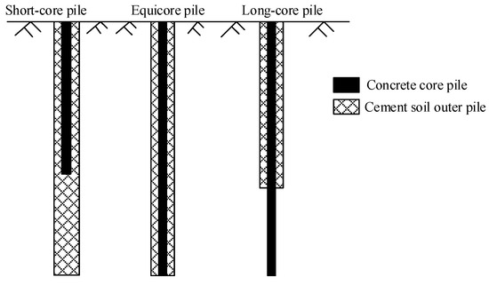
Figure 1.
SDCM piles.
Several research studies have been carried out on the bearing characteristics of SDCM piles under vertical loading. Li et al. [7] reviewed the bearing capacity calculation methods of SDCM piles in existing composite elements. They proposed a modified formula based on the field characteristics. Through laboratory tests, Zhang et al. [8,9] investigated the destabilization damage mode of short-core SDCM pile-reinforced embankment. Voot-tipruex et al. [10] employed field tests to confirm that the SDCM pile was superior to the DCM pile in controlling settlement and deformation under embankment loading. Faro et al. [11] studied the influence of cross-sectional size and length on SDCM piles. The authors demonstrated that the vertical ultimate bearing capacity of SDCM piles increases with the increasing cross-sectional area and length of core piles. It was also found that the influence of the length of core piles is higher than that of the cross-sectional area. By laboratory model tests, Zhou et al. [12] investigated the distribution of vertical stresses in the DCM pile and concrete core along the pile body. They developed a relationship between the lateral and end resistances and the relative displacement. A “sudden increase effect” was identified in vertical stresses at the bottom of the DCM pile with a concrete core. Dong et al. [13] employed an elastic-plastic finite element method (FEM) to investigate the mechanical properties of SDCM piles under vertical loading. This investigation included analyzing the pile–soil stress ratio, vertical stresses in the concrete core, and distribution of lateral friction resistance at the interface between the inner and outer cores along the pile length.
Researchers have also studied the calculation and analysis methods of bearing characteristics of SDCM piles. For instance, Wang et al. [14] developed a simplified calculation method for the change in the load-bearing capacity of statically drilled rooted nodular piles. This method is based on the shear displacement method by introducing the composite modulus of elasticity of the concrete core pile and surrounding cement soil. Zhang et al. [15] studied the interaction between the expanded precast piles and the surrounding soil in the case of vertical bearing based on the shear displacement method and the load transfer principle. Then, they combined them to develop a simplified calculation method for vertical bearing deformation of expanded precast piles. Chen et al. [16] introduced a double exponential function and an ideal elastic-plastic load transfer model to propose a load transfer analysis and calculation method for equal-core SDCM piles in flexible foundations. Yu et al. [17] developed equilibrium differential equations for the concrete core, DCM pile, and surrounding soil based on the load transfer method and obtained the corresponding stress and displacement expressions of these three components. The influence of factors such as the upper load, the ratio of core piles, and the area replacement ratio on the settlement of composite foundations was also evaluated. Whereas many related research studies have been conducted earlier, most of these are based on equal-core piles, and simplified analysis of short-core composite piles is still rare. Today, deep learning [18,19,20] and artificial intelligence [21,22] provide a unique opportunity for predicting the axial force field of piles. Consequently, structural engineering is predictable due to deep learning’s specific ability to handle complex nonlinear structural systems under various conditions. Wu et al. [23] established an in-hole MPTWD (the multipoint traveling wave decomposition) method to detect and characterize the damage of cast-in-place reinforced concrete (RC) piles. This method can be applied to extremely long piles and piles with defects on their top. The feasibility of the proposed method was verified against a substantial amount of data.
Zhang et al. [15] considered the deformation of internal prefabricated piles and the external expansion material of the composite pile under vertical load. The expansion pile was subsequently regarded as a complete pile with a composite elastic modulus of Ecm. The radial interaction between prefabricated piles, expansion materials, and surrounding soil under vertical bearing was analyzed considering the squeezing effect on the surrounding expansion material and soil after the implantation of prefabricated piles, based on the theory of thick-walled cylinders. The composite modulus of elasticity Ecm of the SDCM pile body of expansion piles was derived, but its calculation formula is relatively complex. Wang et al. [14] used the area-weighted average method to calculate the elastic modulus of static drilled bamboo joint piles. The applicability of the area-weighted average method to estimate the composite modulus of elasticity of SDCM piles has not been verified before.
Therefore, this study takes short-core piles as the research object and divides them into composite pile and DCM pile sections. The concept of comprehensive modulus is introduced for the composite pile section. Additionally, the comprehensive modulus is calculated using the area-weighted average method. The applicability of the area-weighted average method to estimate the comprehensive elastic modulus of reinforced composite piles is verified. Besides utilizing the load transfer method theory, the short-core SDCM pile is taken as the research object in this study. Moreover, the finite difference method is adopted to establish a nonlinear simplified calculation method for vertical bearing characteristics of SDCM piles under vertical loading. The study provides insights into such composite piles’ engineering design and applications.
2. Calculation of Composite Modulus of Elasticity of SDCM Pile
The SDCM pile has two interaction interfaces:
- (i)
- The interface of the outer DCM pile and the surrounding soil;
- (ii)
- The interface of the core pile and outer DCM pile.
Previous findings on SDCM piles indicate that the ultimate lateral friction resistance between the DCM pile and surrounding soil is much smaller than the shear strength between the core pile and the DCM pile [24,25]. Zhang et al. [15] regarded an expanded pile as an elastic modulus of Ecm, as shown in Equation (1), with the following basic assumptions: 1. The stress behavior of a composite pile body during axial compression is simplified as the superposition of uniaxial compression and plane strain. 2. In vertical loading, the core pile and its peripheral expansion pile are subjected to separate forces, and their longitudinal and transverse deformations are coordinated. 3. The radial strain of the pile body comprises two parts: radial deformation caused by axial load without lateral confinement and radial deformation caused by confining pressure under lateral confinement.
where
where and are the elastic moduli of the inner precast pile and outer DCM pile, respectively; is the ratio of the cross-sectional area of the inner precast pile to the total area of pile body, ; is the total cross-sectional area of pile body, ; and are the cross-sectional areas of the inner precast pile and outer pile material, respectively; and are the Poisson’s ratios of the inner precast pile and outer pile material, respectively; and are the radii of the inner precast pile and total cross-section radius of the whole pile; is the earth pressure coefficient; is the unit weight of soil; is the vertical strain generated by the pile body; and is the pile length.
The composite section of the short-core SDCM pile was considered in this paper as a monolithic pile with a composite modulus of elasticity of Ecm [15]. This study assumes that the core pile, DCM pile, and the soil around the pile will only undergo vertical deformation to simplify the calculation. In contrast, the radial deformation can be ignored. During vertical loading, there is no displacement between the DCM pile and the core pile. Additionally, the DCM and core piles exhibit elastic deformation. Based on the above assumptions, this study sets the composite modulus of elasticity of the composite pile section as Ecm. Moreover, it calculates it by weighting the average cross-sectional area of the inner and outer piles of the composite pile section [14], as shown in Equation (2):
where and are the elastic moduli of the outer DCM pile and core pile in the composite pile section, respectively; is the pile area, , in which and are the areas of the outer and inner piles, respectively.
The composite modulus of elasticity in the composite pile section of the SDCM pile was calculated using Equations (1) and (2), respectively, while the elastic moduli of the core and outer piles were taken from previous studies in the literature [26,27,28]. The calculated values are presented in Table 1.

Table 1.
Comparison of composite modulus of elasticity obtained by different methods.
The error between the calculation results obtained from the Equation (2) and the method in the literature [15] (Equation (1)) was below 0.5%. Therefore, to simplify the calculation, Equation (2) was utilized to calculate the composite modulus of elasticity of the composite pile section of the SDCM pile.
3. Simplified Analysis Method for Bearing Characteristics of SDCM under Vertical Load
Short-core SDCM piles are more widely applied in actual projects. As shown in Figure 2, a short-core SDCM pile can be divided into a composite pile section and a DCM pile section. In this study, the composite pile section was regarded as monolithic with a composite modulus of elasticity of [15] calculated by Equation (2).
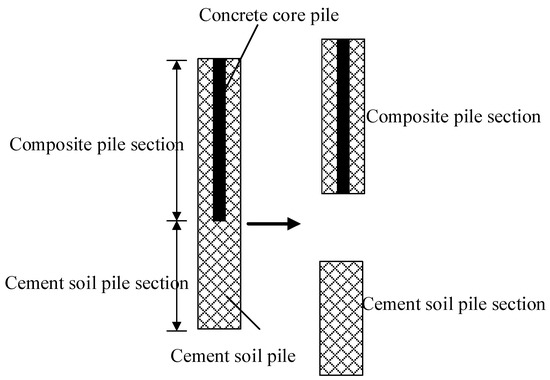
Figure 2.
Schematic diagram of SDCM pile.
3.1. Governing Equation for the Pile
The governing equation for the pile under vertical loading [16] is expressed as Equation (3).
where
where is the pile displacement at the depth ; is the cross-sectional perimeter of the pile; is the elastic modulus of the pile body; and is the lateral friction resistance between the outer DCM pile and the surrounding soil at depth .
An ideal elastoplastic model was adopted for the transfer function of the pile side load at the pile–soil interaction interface, as presented in Figure 3 and Equation (4).
where is the relative displacement between the pile and the soil; is the initial slope of the bifurcation line; is the pile side ultimate friction resistance; and is the ultimate displacement corresponding to the pile side ultimate load.
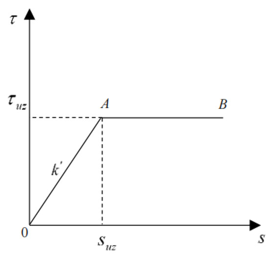
Figure 3.
Ideal elastoplastic model.
The initial tangent stiffness of the soil on the pile side is given by Equation (5).
where is the shear modulus of the soil on the pile side, ; is the pile radius; and is the maximum influence radius of the pile on the surrounding soil, which can be calculated by [29].
The secant stiffness of the soil on the pile side is given by Equation (6).
If , then the governing equation for the pile is transformed into Equation (7).
The ultimate friction resistance can be determined using the method proposed by Chandler (1968) [30] as follows:
where is the average vertical effective stress in the calculated soil layer on the pile side and , , in which is the effective internal friction angle of the soil.
The initial slope of the hyperbola in the transfer function at the pile end can be determined using Equation (9), as suggested by Randolph and Wroth [29].
where is the initial shear modulus or ultimate shear modulus of soil at the pile end and is the Poisson’s ratio of soil at the pile end.
The pile end ultimate resistance can be determined using Equation (10), as proposed by Janbu [31]:
where
where is the pile end ultimate resistance; is the soil cohesion at the pile end; and are the bearing capacity parameters related to the internal friction angle, which can be determined by Equations (12) and (13), respectively; and is the lateral effective stresses at the planar position of the pile end:
where is the angle between the compaction zone at the pile end and the horizontal plane in the Janbu damage model of pile end soil, which varies between 0.33π and 0.58π.
The boundary conditions are as follows:
- (i)
- For the DCM pile section:
For the pile top
where is the vertical loading applied to the top of the DCM pile section.
For the pile end
The pile end load transfer function adopts the hyperbola form, as expressed in Equation (15).
where is the pile end load of the DCM pile section and is the soil displacement below the pile end caused by the load.
The secant stiffness of the soil at the pile end is expressed as Equation (16).
- (ii)
- For the composite pile section:
For the pile top
where is the vertical loading applied to the pile top.
For the pile end
The secant stiffness of the soil at the pile end is given in Equation (18)
where is the displacement at the top of the DCM pile section caused by the load of .
3.2. Solution by the Finite Difference Method
The control equation of the SDCM pile body is a partial differential equation, and its solution is generally challenging. The numerical solution methods for many partial differential equations mainly include traditional numerical methods such as the finite volume method, finite difference method, FEM based on elements or grids, as well as the meshless method [32,33,34,35,36,37]. This study uses the finite difference method (traditional solution) to solve the short-core SDCM. The basic idea of the finite difference method is to discretize the solution domain using a difference grid. This method involves converting the control equation into a different one using a specific formula. Finally, the initial and boundary conditions are combined to solve a system of linear algebraic equations. The finite difference method was used to solve the short-core SDCM pile. The differential discretization schematic diagram along the pile body is illustrated in Figure 4. The pile was discretized into nodes of equal spacing, with each pile segment having the length of . A virtual node was added at the bottom of the pillar. A composite pile section is represented by . Moreover, a cement soil pile section is represented by .

Figure 4.
Schematic diagram of pile nodes.
- (i)
- For the DCM pile section:
Equation (19) can be obtained by differential discretizing the pile’s governing equation.
Equations (20)–(23) can be obtained by performing differential discretization of the boundary conditions as follows:
For the pile top:
The pile end:
Substituting Equations (21) and (23) into Equation (19) yields the following:
Combining Equations (19), (24), and (25) yields the following:
where is the column vector of vertical displacement of the node of the lower DCM pile section, ; is the column vector of vertical loading of the DCM pile section, ; and is the vertical stiffness matrix of the pile, and is expressed in Equation (27).
where .
The vertical displacement along the pile body can be obtained by Equation (26) and is given in Equation (28).
- (ii)
- The composite pile section:
Equation (29) can be obtained by conducting differential discretization of the governing equation of the pile.
The following can be obtained by performing differential discretization of the boundary conditions:
For the pile top:
For the pile end:
Substituting Equations (31) and (33) into Equation (29) yields Equations (34) and (35).
Combining Equations (29), (34), and (35) yields the following:
where is the column vector of vertical displacement of the node of the upper composite pile section, ; is the column vector of vertical loading of composite pile section, ; and is the vertical stiffness matrix of the pile body of the upper composite pile and is given in Equation (37).
where .
The vertical displacement along the load-bearing pile body can be obtained from Equation (37) and is expressed as follows:
The procedure for the nonlinear analysis for a single SDCM pile is as follows:
A vertical loading P1 of 1 kN was applied to the top of the DCM pile section. The soil stiffness at the pile side was taken as the initial tangent stiffness , while that at the pile end was taken as the initial tangent stiffness . The node vertical displacement along the pile body of the DCM pile section was determined by Equation (28).
The secant stiffness of the soil at the pile side and that at the pile end were obtained from the newly derived pile node displacements.
- (a)
- Based on the newly determined secant stiffness of the soil at the pile side and that at the pile end, the node vertical displacement along the pile body and the pile top displacement in the DCM pile section were determined by Equation (28).
- (b)
- Parameter was taken as the iterative control error. When the error exceeded the threshold, the procedural steps presented above, i.e., (c) –(e), were repeated until the iterative error was smaller than the threshold value.
- (c)
- The pile top vertical displacement of the DCM pile section was derived from the above procedures.
- (d)
- The soil stiffness at the pile end of the composite pile section was set to the secant’s stiffness at the top of the DCM pile section (Equation (18)). On the other hand, soil stiffness at the pile side in the composite pile section was set to the initial tangent stiffness of the soil at the pile side.
- (e)
- A vertical loading P0 was applied to the top of the composite pile section.
- (f)
- The node displacement of the pile body in the composite pile section was obtained by Equation (38).
- (g)
- The secant stiffness of the soil at the pile side and that at the pile end were obtained from the newly derived pile node displacements in the composite pile section.
- (h)
- Based on the newly determined secant stiffness of the soil at the pile side and that at the pile end, the vertical node displacement along the pile body and the pile end resistance of the composite pile section were derived from Equation (38) and are given in Equation (39).
- (i)
- Parameter was taken as the iterative control error, and when the error exceeded the threshold value, procedures (c) –(e) were repeated until the iterative error was smaller than the threshold.
- (j)
- When , (b) –-(l) were repeated to derive , i.e., the new pile end resistance in the composite pile section.
- (k)
- Parameter was taken as the iterative control error, and when the error was larger than the threshold, procedures (c) –-(e) were repeated until the iterative error was smaller than the threshold value.
4. Model Validation and Analysis
Li [38] conducted a full-scale field static load test on an equal-core SDCM pile. The diameter and length of the composite pile were 600 mm and 14 m, respectively. The core pile was a concrete-cored equal-section square pile with a section size of 270 × 270 mm. The moduli of elasticity of the core pile and outer DCM pile were Ep = 4.2 × 10⁴ MPa and Ec = 150 MPa, respectively. As for the above field static load test [38], Chen et al. [16] utilized the results of multiple sets of tests on the DCM pile–soil friction characteristics using Wang [39] as the reference to determine the load transfer parameters at the DCM pile–soil interface. The initial tangent stiffness of the pile side and the pile end were and , respectively. The ultimate friction resistance values of the pile side and pile end were 65 kPa and 285.71 kPa, respectively. The composite modulus of elasticity of this SDCM pile was determined to be Ecm = 10945.7 MPa using Equation (2). The proposed simplified method was tested on the above data from the literature. The corresponding results were compared to Li’s test results [38] and Chen et al.’s calculation results [16]. The findings are summarized in Figure 5. The results obtained through the simplified method proposed herein are consistent with the test results.
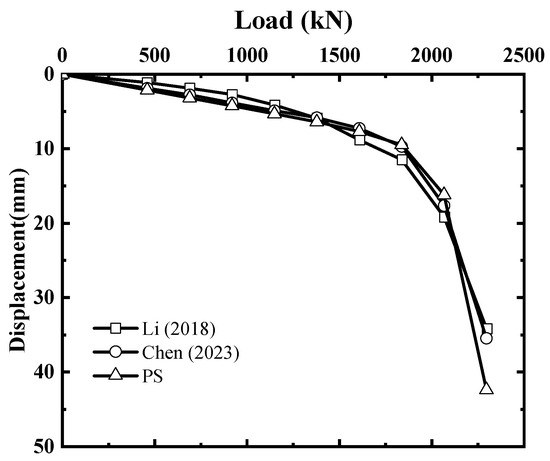
Figure 5.
Comparison of Q-S curves obtained by different methods [16,26].
Furthermore, the vertical bearing characteristics of the SDCM pile with different core-to-length ratios (the ratio of the length of the core pile to the length of the DCM pile) under vertical loading were calculated to explore the effect of the core pile length on the vertical bearing characteristics of the SDCM pile under vertical loading. The material parameters and dimensions of the pile are presented in Table 2 and Table 3, respectively.
Table 2.
Material parameters.
Table 3.
Dimensions of the pile.
In order to eliminate the influence of boundary conditions, both the length and width of the FEM model were taken as 40 m. The distance of the soil in the analyzed area from the pile side to all sides of the model was greater than 15 times the diameter of the DCM pile. The height of the model was 50 m. The distance from the pile end to the bottom of the model was 20 m, i.e., more than 15 times the diameter of the DCM pile. The interaction type between the pile and soil interface is face-to-face contact. In contrast, the contact type between the pile and soil contact surface is binding contact. Constrain the horizontal and vertical directions of soil elements and fully constrain the bottom of the model. The finite elements are designated as C3D8R, and the mesh density is arranged according to the distance from the pile, as shown in Figure 6.

Figure 6.
Model network and cloud diagrams.
According to regulation 4.4.1 in the “Technical Code for Testing of Building Foundation Piles” (JGJ106-2014) [40], the loading at the pile top with a settlement equal to 0.05 times the diameter can be taken as the ultimate vertical bearing capacity of the pile for a pile with a diameter exceeding 800 mm. The results of FEM simulations confirmed that the ultimate bearing capacities of the SDCM pile were 7600 kN, 6000 kN, and 4400 kN when the core-to-length ratios were 1.0, 0.7, and 0.5, respectively. The regulation also suggests that the characteristic value of the vertical bearing capacity of a single pile should be taken as 50% of the ultimate bearing capacity of a single pile, indicating that one-half of the ultimate bearing capacity is taken as the working load in this paper [41]. In this scenario, the working loads were 3800 kN, 3000 kN, and 2200 kN for the core-to-length ratios of 1.0, 0.7, and 0.5, respectively.
Figure 7a,b depict the variation in the pile top displacement and pile end resistance, respectively, with the number of discrete nodes on the pile body (the iterative control error is 10−6) under a working load (3000 kN) with a core-to-length ratio of 0.7 and a core content of 0.16. When the number of discrete nodes on the pile body is n > 30, the pile top displacement and end resistance remain almost unchanged. Figure 7c,d show the variation curves of axial force and lateral friction resistance, respectively, along the pile body with the number of discrete nodes on the pile body under a working load (3000 kN) with a core-to-length ratio of 0.7 and a core content of 0.16. It can be seen from the figure that when n > 30, the axial force and lateral friction curves of the pile body remain almost unchanged for different numbers of discrete nodes on the pile body. Therefore, the calculation method in this study has good convergence. The following calculations in this research were all taken as n = 100.

Figure 7.
Comparison of calculation results for SDCM pile with different numbers of discrete nodes.(a) Displacement of the pile top, (b) Resistance at the pile end, (c) Axial force of the pile body and (d) Frictional resistance on the pile side.
Figure 8 shows the load–displacement curves for the top of the SDCM pile at different core-to-length ratios and a ratio of the core pile of 0.16. The vertical bearing capacity and pile top stiffness of the SDCM pile increase with the length of the core pile.

Figure 8.
Load–displacement curves for the pile top at different core-to-length ratios.
The distributions of axial force and lateral friction resistance along the SDCM pile with different core-to-length ratios under different working loads are presented in Figure 9 and Figure 10, respectively. For SDCM piles, the axial force and frictional resistance at the lower part of the pile become increasingly smaller with the decrease in the core-to-length ratio. As indicated in Figure 9c and Figure 10c, the part near the pile end (2–3 m) was almost force-free when the core-to-length ratio was 0.5.

Figure 9.
Axial forces of the pile body at different core-to-length ratios. (a) The core to length ratio is 1, (b) The core to length ratio is 0.7 and (c) The core to length ratio is 0.5.

Figure 10.
Pile lateral friction resistance at different core-to-length ratios. (a) The core to length ratio is 1, (b) The core to length ratio is 0.7 and (c) The core to length ratio is 0.5.
The difference between the simplified method and the finite element (especially the axial force at the pile end) can be observed in the axial force at the pile end, as shown in Figure 11. This error may be attributed to the established finite element model being three-dimensional. In contrast, the theoretical model in this study was obtained through a simplified one-dimensional nonlinear model.
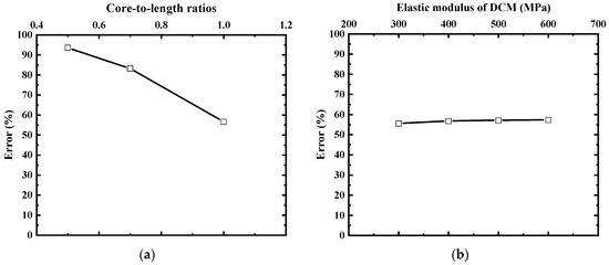
Figure 11.
The variation curve of the relative error of pile end axial force with the core-to-length ratio and the elastic modulus of the DCM pile. (a) Core-to-length ratios and (b) Elastic modulus of DCM.
Figure 11a shows the variation of the relative error of the axial force at the pile end with the core-to-length ratio calculated by the simplified method and the proposed three-dimensional finite element simulation (the core content is 0.16 under working load, while other working conditions can be found in Figure 9 and Figure 10). According to Figure 11a, the error relative to the finite element model will decrease with an increase in the core-to-length ratio. However, when the core-to-length ratio is 1 (i.e., an equal-core pile), the error is still higher than 50%. It can be concluded that the change in the core-to-length ratio cannot reduce the error.
Figure 11b shows the relative error of the pile end axial force obtained by the simplified method and the proposed three-dimensional finite element simulation as a function of the elastic modulus of the DCM pile (under a working load, with a core content of 0.16). The change in the elastic modulus of the DCM pile does not significantly affect the error between the pile end axial force calculated by the simplified method and the finite element simulation. In summary, the ratio of core length to pile soil’s elastic modulus is not an important parameter affecting this error. Further in-depth research will be conducted on this issue in subsequent studies.
Figure 12 shows the variation in pile top displacement with the length of the DCM pile section when a working load of 2200 kN (core-to-length ratio of 0.5) was applied to the pile top. When the DCM pile length was <10 m, the vertical displacement at the pile top increased with decreased DCM pile length. When the pile length exceeded 10 m, the vertical displacement at the top remained almost unchanged with the increase in the length of the DCM pile. Figure 9c, Figure 10c, and Figure 11 confirmed a reasonable core-to-length ratio for the SDCM pile in a specific scenario. When the core pile length was given, an excessively long DCM pile section made its lower part force-free. The appropriate core pile length should be determined in the actual engineering project to avoid unnecessary material wastage.

Figure 12.
Variation curve of pile top displacement with the DCM pile length.
Figure 13 shows the variations in the vertical displacement of the pile top with the ratio of the core pile when the corresponding vertical working loads (3800, 3000, and 2200 kN) in the case of the ratio of the core pile being 0.16. On the other hand, core-to-length ratios of 1, 0.7, and 0.5 were applied to the pile. With the increase in the ratio of the core pile, the pile-top settlement was increasingly smaller. Moreover, the reduction in pile-top settlement gradually slowed. An optimum ratio of the core pile for the SDCM pile was also determined. The increase in the ratio of the core pile beyond the optimal ratio provided limited control over the pile foundation settlement, which is consistent with [15].

Figure 13.
Variation curve of pile top displacement with the ratio of core pile.
5. Conclusions
This study introduced the concept of composite modulus of elasticity for the SDCM pile, which was calculated using the area-weighted average method. Based on the load transfer method, a nonlinear simplified analysis method for the equal-core and short-core SDCM piles under vertical loading was established using the finite difference method. Moreover, the bearing characteristics of the SDCM pile under vertical loading were analyzed. The following conclusions are drawn from the obtained results:
- (1)
- The area-weighted average method was used to calculate the composite elastic modulus of the composite pile section of the reinforced core composite pile. Compared to the analytical method, the error is below 0.5%, with sufficient accuracy.
- (2)
- The simplified calculation method established in this study is computationally stable. When the iterative control error was set to 10−6, as the number of discrete nodes n on the pile increased, the calculation results tended to be stable and converged well when n > 30.
- (3)
- The vertical bearing capacity and pile top stiffness of the SDCM pile increased with the core pile length.
- (4)
- There was a reasonable core-to-length ratio for SDCM piles in specific scenarios. When the length of the core pile was fixed, an excessively long DCM pile section resulted in its lower part being force-free. The appropriate core pile length should be determined in the actual project to avoid unnecessary material waste.
- (5)
- There was an optimum ratio of the core pile for the SDCM pile. Additionally, the increase in the ratio of the core pile beyond the optimal ratio provided limited control of pile foundation settlement.
In summary, the simplified method proposed in this paper can provide some thoughts and directions for future reinforced composite pile group foundations. However, the relative error in the axial force at the pile end still exists. Artificial intelligence and deep learning can be combined to address this issue. Finally, additional in-depth research on reinforced SDCM piles will be conducted, a more reasonable model will be established, and the actual engineering situation will be more accurately reflected.
Author Contributions
Conceptualization, Y.J. and Y.G.; software, Y.J. and Y.G.; validation, Y.J., Y.G. and F.L.; formal analysis, Y.G., Y.Z. and Z.Z.; investigation, Y.J., Y.Z. and Z.Z.; writing—original draft preparation, Y.J.; writing—review and editing, Y.J., Y.Z. and Y.G.; funding acquisition, Y.J. and Z.Z. All authors have read and agreed to the published version of the manuscript.
Funding
This work was financially supported by the National Natural Science Foundation for Young Scientists of China (No. 51608548) and the natural science foundation of the Henan Province (No. 222300420596).
Data Availability Statement
The datasets used during the current study are available from the corresponding author upon reasonable request.
Conflicts of Interest
The authors have no conflicts of interest to declare. All co-authors have observed and affirmed the contents of the paper and there is no financial interest to report.
References
- Zhao, Y.; Zhang, Z.; Ye, G.; Cai, Y. Numerical study on performance of composite foundation with stiffened deep mixed columns[C]//. In Proceeding of the 2015 National Engineering Geology Academic Annual Meeting Science Press; Geology Committee of Geological Society of China: Beijing, China, 2015. [Google Scholar]
- Wonglert, A.; Jongpradist, P. Impact of reinforced core on performance and failure behavior of stiffened deep cement mixing piles. Comput. Geotech. 2015, 69, 93–104. [Google Scholar] [CrossRef]
- Li, P.; An, H.; Wang, L.; Tan, W.; Meng, Y.; Li, K.; Zhang, T. Comparative analysis of MC strength composite piles and cast-in-place piles in an engineering project. Build. Sci. 2021, 37, 147–152. [Google Scholar]
- Thompson, G.R.; Long, L.G. Hibernia geotechnical investigation and site characterization. Can. Geotech. J. 1989, 26, 653–678. [Google Scholar] [CrossRef]
- Hu, X.; Kawata, M.; Nakanishi, Y.; Li, J. Application of jet grouting pile method in Japan. Chin. J. Geotech. Eng. 2010, 32 (Suppl. S2), 410–413. [Google Scholar]
- Deng, Y.; Zheng, G.; Chen, C.; Cui, W.; Song, E.; Diao, Y.; Fu, Y. Review of SCM Composite Column pile. Constr. Technol. 2018, A04, 3. [Google Scholar]
- Li, L.; Liu, S.; Zhang, D.; Deng, Y. Bearing Capacity Calculations of Strength Composite Piles. Chin. J. Undergr. Space Eng. 2015, 11 (Suppl. S1), 43–47. [Google Scholar]
- Zhang, Z.; Chen, Y.; Ye, G.; Xiao, Y.; Wang, M. Model test on stability failure of short-cored stiffened deep mixed column-supported embankment. J. Eng. Geol. 2019, 27, 7. [Google Scholar]
- Zhang, Z.; Rao, F.; Ye, G. Analytical modeling on consolidation of stiffened deep mixed column-reinforced soft soil under embankment. Int. J. Numer. Anal. Methods Geomech. 2020, 44, 137–158. [Google Scholar] [CrossRef]
- Voottipruex, P.; Bergado, D.T.; Suksawatt, T.; Jamsawang, P.; Cheang, W. Behavior and simulation of deep cement mixing (DCM) and stiffened deep cement mixing (SDCM) piles under full scale loading. Soils Found. 2011, 51, 307–320. [Google Scholar] [CrossRef]
- Faro, V.P.; Consoli, N.C.; Schnaid, F. Field tests on laterally loaded rigid piles in cement treated soils. J. Geotech. Geoenviron. Eng. 2015, 141, 06015003. [Google Scholar] [CrossRef]
- Zhou, J.; Gong, X.; Wang, K.; Zhang, R.; Yan, T. Model test on load transfer mechanism of a static drill rooted modular pile. J. Zhejiang Univ. (Eng. Sci.) 2015, 49, 531–537. [Google Scholar]
- Dong, P.; Qin, R.; Chen, Z. FEM study of concrete-cored DCM pile. Rock Soil Mech. 2003, 24, 344–348. [Google Scholar]
- Wang, Z.; Zhang, R.; Xie, X.; Fang, P.; Zheng, L.; Li, J.; Zhu, D. Field tests and simplified calculation method for static drill rooted nodular pile. Adv. Civ. Eng. 2019, 2019 Pt 9, 5841840. [Google Scholar] [CrossRef]
- Zhang, H.; Liu, W.; He, L.; Xu, Y.; Zhou, T.; Zhang, Y. Simplified calculation method for vertical bearing deformation of pre-bored grouting reamed precast pile. J. Railw. Sci. Eng. 2022, 19, 120–128. [Google Scholar] [CrossRef]
- Chen, C.; Chen, S.; Zhu, S.; Cai, H. Analysis on load transfer behaviors of equal-core stiffened deep mixed pile under flexible foundation. J. Hunan Univ. (Nat. Sci. Ed.) 2023, 50, 152–160. [Google Scholar] [CrossRef]
- Yu, J.; Xu, S.; Yang, X.; Chen, Z.; Gong, X. Settlement calculation of composite foundation with concrete-core DCM pile under rigid foundation. J. Cent. South Univ. (Nat. Sci. Ed.) 2020, 51, 2111–2120. [Google Scholar] [CrossRef]
- Bianca, W.T.; Marzia, T. Navigating applied artificial intelligence (AI) in the digital Era: How Smart buildings and Smart cities become the key to sustainability. Artif. Intell. Appl. 2023, 1, 230–243. [Google Scholar] [CrossRef]
- Saeed, K.; Mehdi, G.; Seyedeh, M.M.; Hadi, Z.; Basheer, R.; Muhammad, F.K.; Yang, L. A survey on weak pseudoorders in ordered hyperstructures. Artif. Intell. Appl. 2023, 1–5. [Google Scholar] [CrossRef]
- Lama, A.; Taha, K. Supportive environment for better data management stage in the cycle of ML process. Artif. Intell. Appl. 2023, 1–8. [Google Scholar] [CrossRef]
- Sunil, K.M.; Liu, X.; Tsuyoshi, M. Feature selection: Key to enhance node classification with graph neural networks. CAAI Trans. Intell. Technol. 2023, 8, 14–28. [Google Scholar] [CrossRef]
- Hemanth, G.; Niu, N.; Yang, Y.L.; Matthew, V.D. Deep learning’s fitness for purpose: A transformation problem frame’s perspective. CAAI Trans. Intell. Technol. 2023, 8, 343–354. [Google Scholar] [CrossRef]
- Wu, J.T.; Hesham, M.; Wang, K.H. Pile damage detection using machine learning with the multipoint traveling wave decomposition method. Sensors 2023, 23, 8308. [Google Scholar] [CrossRef]
- Qian, Y.; Xu, Z.; Deng, Y.; Sun, G. Engineering application and test analysis of strength composite piles. Chin. J. Geotech. Eng. 2013, 35, 998–1001. [Google Scholar]
- Voottipruex, P.; Suksawat, T.; Bergado, D.T. Numerical simulations and parametric study of SDCM and DCM piles under full scale axial and lateral loads. Comput. Geotech. 2011, 38, 318–329. [Google Scholar] [CrossRef]
- Li, Y. The finite element simulation and analysis of strength composite pile vertical bearing capacity. Low Temp. Build. Technol. 2018, 40, 135–137. [Google Scholar] [CrossRef]
- Li, J.; Deng, Y.; Song, G.; Ling, G. Analysis of load-bearing mechanism of composite foundation of plain concrete reinforced cement-soil mixing piles. Rock Soil Mech. 2009, 30, 181–185. [Google Scholar] [CrossRef]
- Yu, J.; Yang, X.; Zhou, J.; Xu, S.; Gong, X.; Zhao, X. Research on working behavior of concrete-cored DCM pile composite foundation. J. Cent. South Univ. (Nat. Sci. Ed.) 2022, 53, 2606–2618. [Google Scholar]
- Randolph Mark, F.; Wroth, C.P. Analysis of Deformation of Vertically Loaded Piles. J. Geotech. Eng. Div. 1978, 104, 1465–1488. [Google Scholar] [CrossRef]
- Pile Foundation Engineering Handbook Compilation Committee. Pile Foundation Engineering Handbook; China Architecture & Building Press: Beijing, China, 2016; p. L-1104. [Google Scholar]
- Janbu, N. Static bearing capacity of friction piles. In Sechste Europaeische Konferenz Fuer Bodenmechanik Und Grundbau; Institut Fuer Grundbau und Bodenmechanik: Wien, Austria, 1976; Volume 1.2. [Google Scholar]
- Batra, R.C.; Zhang, G.M. Modified Smoothed Particle Hydrodynamics (MSPH) basis functions for meshless methods, and their application to axisymmetric Taylor impact test. J. Comput. Phys. 2008, 227, 1962–1981. [Google Scholar] [CrossRef]
- Bai, Y.B.; Niedzwecki, J.M. Meshfree analysis of structures modeled as extensible slender rods. Eng. Struct. 2018, 156, 82–91. [Google Scholar] [CrossRef]
- Lin, J.; Li, J.; Guan, Y.J.; Zhao, G.Q.; Naceur, H.; Coutellier, D. Geometrically nonlinear bending analysis of functionally graded beam with variable thickness by a meshless method. Compos. Struct. 2018, 189, 239–246. [Google Scholar] [CrossRef]
- Kiani, K.; Zur, K.K. Vibrations of double-nanorod-systems with defects using nonlocal-integral surface energy-based formulations. Compos. Struct. 2021, 256, 113028. [Google Scholar] [CrossRef]
- Kiani, K. Column buckling of magnetically affected stocky nanowires carrying electric current. J. Phys. Chem. Solids 2015, 83, 140–151. [Google Scholar] [CrossRef]
- Kiani, K. Nonlocal-integro-differential modeling of vibration of elastically supported nanorods. Phys. E Low-Dimens. Syst. Nanostructures 2016, 83, 151–163. [Google Scholar] [CrossRef]
- Li, J. Experimental Study on Load Transfer Mechanism of Reinforced Mixing Pile; Tianjin University: Tianjin, China, 2006. [Google Scholar]
- Wang, R. Research on Contact Performance of Interface between Flexible Column and Soil in Soft Clay; Hunan University of Technology: Zhuzhou, China, 2017. [Google Scholar]
- JGJ106-2014; Ministry of Housing and Urban-Rural Development of the People’s Republic of China. Technical Code for Building Foundation Pile Detection. China Architecture & Building Press: Beijing, China, 2014.
- Wang, H. Bridge Piers and Foundation Engineering; China Railway Press: Beijing, China, 2005. [Google Scholar]
Disclaimer/Publisher’s Note: The statements, opinions and data contained in all publications are solely those of the individual author(s) and contributor(s) and not of MDPI and/or the editor(s). MDPI and/or the editor(s) disclaim responsibility for any injury to people or property resulting from any ideas, methods, instructions or products referred to in the content. |
© 2024 by the authors. Licensee MDPI, Basel, Switzerland. This article is an open access article distributed under the terms and conditions of the Creative Commons Attribution (CC BY) license (https://creativecommons.org/licenses/by/4.0/).